EP3164288B1 - Removal prevention device for anti-siphoning devices for tanks - Google Patents
Removal prevention device for anti-siphoning devices for tanks Download PDFInfo
- Publication number
- EP3164288B1 EP3164288B1 EP15733737.9A EP15733737A EP3164288B1 EP 3164288 B1 EP3164288 B1 EP 3164288B1 EP 15733737 A EP15733737 A EP 15733737A EP 3164288 B1 EP3164288 B1 EP 3164288B1
- Authority
- EP
- European Patent Office
- Prior art keywords
- ring
- sliders
- prevention device
- annular guide
- removal prevention
- Prior art date
- Legal status (The legal status is an assumption and is not a legal conclusion. Google has not performed a legal analysis and makes no representation as to the accuracy of the status listed.)
- Active
Links
Images




Classifications
-
- B—PERFORMING OPERATIONS; TRANSPORTING
- B60—VEHICLES IN GENERAL
- B60K—ARRANGEMENT OR MOUNTING OF PROPULSION UNITS OR OF TRANSMISSIONS IN VEHICLES; ARRANGEMENT OR MOUNTING OF PLURAL DIVERSE PRIME-MOVERS IN VEHICLES; AUXILIARY DRIVES FOR VEHICLES; INSTRUMENTATION OR DASHBOARDS FOR VEHICLES; ARRANGEMENTS IN CONNECTION WITH COOLING, AIR INTAKE, GAS EXHAUST OR FUEL SUPPLY OF PROPULSION UNITS IN VEHICLES
- B60K15/00—Arrangement in connection with fuel supply of combustion engines or other fuel consuming energy converters, e.g. fuel cells; Mounting or construction of fuel tanks
- B60K15/03—Fuel tanks
- B60K15/04—Tank inlets
- B60K15/0403—Anti-siphoning devices
Definitions
- the present invention relates to a removal prevention device for anti-siphoning devices for tanks.
- tanks for motor vehicles which are substantially constituted by very capacious containers into which the insertion of the fuel is done by way of an adapted inlet.
- Such tanks are usually arranged adjacent to the chassis of the vehicle, at preset heights both from the ground and from the loading surface, in a sheltered area, usually in the space between two wheel axles.
- barrier system against extracting Diesel fuel is arranged on the bottom of the tube of the inlet of the anti-siphoning device fitted on the tank, such tube will be submerged completely once the tank has been filled with fuel.
- a further problem is constituted by the necessity to connect the anti-siphoning device fitted with the obstruction to the mouth of the tank;
- the conventional coupling systems involve either the use of metallic elements to be deformed, such as for example metallic tongues, or perforation and riveting of an anti-theft ring onto the tank body.
- connection and removal prevention device for connecting an antitheft device to a fuel tank to which an end adapter for introducing fuel is welded, comprising means adapted to allow, once the antitheft device has been inserted and partially rotated within the tank, non-removable interconnection with respect to the adapter.
- the aim of the present invention is therefore to resolve the above mentioned technical problems, eliminating the drawbacks in the cited known art, by devising a device that can be associated with an anti-siphoning device for conventional tanks while at the same time making it possible to prevent the fraudulent removal thereof therefrom.
- an object of the invention is to provide a device that can be associated with and at the same time rapidly and easily removed from an anti-siphoning device for conventional tanks.
- Another object is to provide a device according to the invention that is structurally simple and is low cost.
- a removal prevention device for anti-siphoning devices for tanks which comprises a second ring which is provided with an axial tube and with which a third ring can be associated which can be coupled to said tank, characterized in that said second ring has an annular guide, concentric to said axial tube, on which at least one slider slides, oscillating with respect to a pivot associated with said third ring, there being, adjacent to said annular guide, at least one first seat for the temporary engagement of said at least one slider and at least one second seat for an elastically deformable element which protrudes within said annular guide, one or more screws being associated radially with said second ring and affecting or not affecting said annular guide.
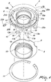
- the reference numeral 1 generally designates a removal prevention device which is applied to a conventional anti-siphoning device 1a for tanks 2 of vehicles of the type with a vertical or oblique connector.
- the removal prevention device 1 comprises a first ring 3, which is usually used as an interconnection element to a cap, which, in the specific embodiment shown, is annular and is perforated axially; such ring is associated, or rendered integral so as to constitute a single element, with an underlying second ring 4, which is substantially T-shaped in cross-section, perforated axially and provided with a first head 5 from the perimetric rim of which a wall 6 and an axial tube 7 protrude, on the opposite side with respect to the first ring 3.
- the first ring 3 may be substituted by a cap or by a valve or by any other means adapted to close the entry port of the device 1.
- a T-shaped third ring 8 is associated with the second ring 4 and comprises therefore a second head 9 which can be associated internally, for example by screwing or by fixing in a bayonet-like manner, with the wall 6, and an externally threaded stem 10 which is arranged concentrically and externally to the axial tube 7.
- a tank inlet with an internal thread instead of external can be used; in this case the third ring 8 will have a stem 10 of greater diameter and be threaded internally.
- the third ring 8 is kept associated with the second ring 4 by way of a retaining ring or "C-clip" 11 in elastic steel.
- the set of the first ring 3, second ring 4, and third ring 8 can thus be coupled to the tank 2.
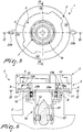
- the second ring 4 has, at the inner surface of the first head 5 which is directed toward the third ring 8, an annular guide 12 on which, in the specific embodiment shown, a pair of sliders 13a, 13b slide.
- annular ridge 14 protrudes from the inner surface of the first head 5; this forms, together with the outer lateral surface of the axial tube 7, a guided path within which each one of the sliders 13a, 13b can lie.
- Each one of the sliders 13a, 13b is substantially shaped like a parallelepiped with a modest length and a width that is smaller than that of the annular guide 12 and with rounded ends 15; a first through hole 16 is provided in each slider at right angles to the surface that slides on the annular guide 12 and acting as a seat for a pivot 17a, 17b for the pivoting of the sliders at adapted second holes 18 which are provided at the underlying flat surface of the second head 9 of the third ring 8.
- Each one of the sliders 13a, 13b is therefore allowed to oscillate at the annular guide 12 so that the respective ends 15 can be kept adjacent to the annular ridge 14 or one of them can be distanced from it and be arranged adjacent to the outer lateral surface of the axial tube 7.
- a pair of first seats 19a, 19b are provided at the inner lateral surface of the annular ridge 14 for the temporary engagement of one of the ends 15 of the sliders 13a, 13b.
- the shape of the pair of first seats 19a, 19b is such that an end 15 of the sliders 13a, 13b is forced into them following a clockwise rotation imparted to the second ring 4.
- a pair of elastically deformable elements 20a, 20b contribute to forcing the placement of the ends 15 of the sliders 13a, 13b into the first seats 19a, 19b and are constituted by rings made of plastic material which can be accommodated at adapted second seats 21a, 21b which are provided at the annular ridge 14 in a region that is adjacent to the first ends 15.
- the shape structure of the second seats 21a, 21b and of the elastically deformable elements 20a, 20b is such that these latter items, once inserted into the second seats 21a, 21b, protrude from them so as to affect part of the space that lies above the annular guide 12 on which the sliders slide.
- One or more screws 22a, 22b of the type that advantageously have a proprietary head, and which have a length such that they can arrange one of their ends beyond the annular ridge 14 so as to thus affect the space of the annular guide 12, are furthermore associated radially, at third holes 30a, 30b, at the outer lateral surface of the second ring 4: in this case the screws prevent any and all rotation of the second ring 4 in that they interact with the sliders 13a, 13b, blocking the sliding thereof.
- the first end 23 of a duct 24, which protrudes with its second end 25 within the tank 2, can be arranged and is associated rotatably.
- the duct 24 is substantially cylindrical and a plurality of axial slots 26, which are adapted to allow the venting of the air from the tank 2, are provided at the outer lateral surface of the first end 23.
- the pair of fourth and fifth holes 27, 28a, 28b are mutually axially aligned so as to allow the placement of a pair of pivots 29a, 29b which allow the rotatable connection of the duct 24 to the axial tube 7.
- the duct 24 can thus oscillate with respect to the axial tube 7 by a desired angle.
- step 31 which constitutes an abutment for the end of the dispensing duct of a nozzle of the fuel pump once it is arranged inside the device 1.
- An ogive 32 is associated inside the second end 25 of the duct 24 and is adapted to guide and direct the flow of the fuel according to a fluid stream.
- the ogive 32 is provided in a downward region with means which are adapted to space the ogive 32 apart from the inner lateral surface of the duct 24 and which are adapted to prevent the insertion of tubes to draw fuel; the means are constituted by a flat spring 33 which is folded in a zigzag arrangement and is then wound at an annular slot 34 which is provided in a downward region with respect to the ogive 32 and abuts against the inner lateral surface of the duct 24.
- the second end 25 of the duct 24 is detachably associable with a dome 34 for supporting and containing the spring 33.
- a gasket 35 can be associated coaxially with the stem 10 of the third ring 8.
- a clockwise rotation, for screwing the device to an inlet for inserting the fuel, is allowed by the fact that the sliders 13a, 13b enter the seats 19a, 19b assisted by the elastic bodies 20a, 20b, thus locking the rotation of the third ring 8, which is threaded with respect to the whole of the rest of the device; the effect is that by rotating the anti-siphoning device, the assembly of the first ring, the second ring and the third ring makes a single body and the device is screwed to the inlet.
- An anticlockwise rotation in order to unscrew the device from the inlet for inserting the fuel, can be achieved only by authorized personnel who must be equipped with adapted means.
- the movement of the second ring 8 can be locked with respect to the whole of the rest of the device in both directions, allowing the technician to unscrew the device from the inlet of the tank if for example it should be necessary for maintenance.
- the invention fully achieves the intended aim and objects, a device being devised which, associated detachably or otherwise with an anti-siphoning device for conventional tanks, simultaneously makes it possible to prevent the fraudulent removal thereof.
Landscapes
- Engineering & Computer Science (AREA)
- Life Sciences & Earth Sciences (AREA)
- Sustainable Development (AREA)
- Sustainable Energy (AREA)
- Chemical & Material Sciences (AREA)
- Combustion & Propulsion (AREA)
- Transportation (AREA)
- Mechanical Engineering (AREA)
- Cooling, Air Intake And Gas Exhaust, And Fuel Tank Arrangements In Propulsion Units (AREA)
- Jet Pumps And Other Pumps (AREA)
Priority Applications (1)
| Application Number | Priority Date | Filing Date | Title |
|---|---|---|---|
| PL15733737T PL3164288T3 (pl) | 2014-07-04 | 2015-07-02 | Urządzenie zapobiegające wyjmowaniu urządzeń antysyfonowych dla zbiorników |
Applications Claiming Priority (2)
| Application Number | Priority Date | Filing Date | Title |
|---|---|---|---|
| ITTV20140098 | 2014-07-04 | ||
| PCT/EP2015/065065 WO2016001346A1 (en) | 2014-07-04 | 2015-07-02 | Removal prevention device for anti-siphoning devices for tanks |
Publications (2)
| Publication Number | Publication Date |
|---|---|
| EP3164288A1 EP3164288A1 (en) | 2017-05-10 |
| EP3164288B1 true EP3164288B1 (en) | 2018-07-11 |
Family
ID=51655929
Family Applications (1)
| Application Number | Title | Priority Date | Filing Date |
|---|---|---|---|
| EP15733737.9A Active EP3164288B1 (en) | 2014-07-04 | 2015-07-02 | Removal prevention device for anti-siphoning devices for tanks |
Country Status (5)
| Country | Link |
|---|---|
| EP (1) | EP3164288B1 (pl) |
| BR (1) | BR112016029961A2 (pl) |
| ES (1) | ES2690193T3 (pl) |
| PL (1) | PL3164288T3 (pl) |
| WO (1) | WO2016001346A1 (pl) |
Families Citing this family (2)
| Publication number | Priority date | Publication date | Assignee | Title |
|---|---|---|---|---|
| GB2548351A (en) * | 2016-03-14 | 2017-09-20 | Tiss Ltd | Anti-siphon device |
| CN108790800B (zh) * | 2018-06-06 | 2023-08-01 | 安达市雄励电气信号设备装置制造有限公司 | 一种油箱防盗装置 |
Family Cites Families (1)
| Publication number | Priority date | Publication date | Assignee | Title |
|---|---|---|---|---|
| IT1391205B1 (it) * | 2008-09-22 | 2011-11-18 | Lago Accessori S R L | Dispositivo di connessione e antirimozione, particolarmente per un dispositivo antifurto ad un serbatoio di carburante. |
-
2015
- 2015-07-02 BR BR112016029961A patent/BR112016029961A2/pt not_active Application Discontinuation
- 2015-07-02 PL PL15733737T patent/PL3164288T3/pl unknown
- 2015-07-02 EP EP15733737.9A patent/EP3164288B1/en active Active
- 2015-07-02 WO PCT/EP2015/065065 patent/WO2016001346A1/en not_active Ceased
- 2015-07-02 ES ES15733737.9T patent/ES2690193T3/es active Active
Non-Patent Citations (1)
| Title |
|---|
| None * |
Also Published As
| Publication number | Publication date |
|---|---|
| PL3164288T3 (pl) | 2019-03-29 |
| EP3164288A1 (en) | 2017-05-10 |
| BR112016029961A2 (pt) | 2017-08-22 |
| WO2016001346A1 (en) | 2016-01-07 |
| ES2690193T3 (es) | 2018-11-19 |
Similar Documents
| Publication | Publication Date | Title |
|---|---|---|
| EP0230890B1 (de) | Blendenring | |
| CN108136296B (zh) | 过滤器插入件和过滤器设备 | |
| US10226996B2 (en) | Filler neck closure assembly | |
| EP2429849B1 (en) | Anti-siphon device | |
| US20210230850A1 (en) | Apparatus and method for valve cartridge extraction | |
| US7735529B2 (en) | Dripless nozzle | |
| EP3164288B1 (en) | Removal prevention device for anti-siphoning devices for tanks | |
| EP2300256A2 (de) | Einsatzelement für einen zur tankstellenseitigen befüllung mit harnstoff geeigneten behälter | |
| MX2008012570A (es) | Entrada de tanque anti-sifon. | |
| US20100229982A1 (en) | Fluid distributor and collection device with collapsible laterals and knuckles | |
| ITTV20080119A1 (it) | Dispositivo antifurto, particolarmente per impedire la estrazione di carburante da serbatoi | |
| WO1994016985A1 (de) | Sicherheitsvorrichtung für einen ventileinsatz an einem getränkefass | |
| US9447908B2 (en) | Anti-siphon assembly | |
| US10266049B2 (en) | Anti-siphoning device, particularly for preventing the extraction of fuel from tanks | |
| US8459483B2 (en) | Anti-siphoning device for fuel tanks | |
| DE112015002539T5 (de) | Harnstofftank | |
| EP3429882B1 (en) | Fuel tank inlet | |
| US2038517A (en) | Receptacle closure | |
| US1019317A (en) | Faucet. | |
| WO2015087147A1 (en) | Safety lock closure device for fuel tanks | |
| DE102008045154A1 (de) | Anordnung aus Kraftstoffrohr und Geberkopf sowie Verfahren zum Bereitstellen einer solchen | |
| KR20060055126A (ko) | 차량의 연료 주입 구조 | |
| US20090058074A1 (en) | Blocking device | |
| WO2005012158A1 (en) | A spear valve with a blow-out preventing device | |
| KR20210067200A (ko) | 정수필터 장착장치 |
Legal Events
| Date | Code | Title | Description |
|---|---|---|---|
| STAA | Information on the status of an ep patent application or granted ep patent |
Free format text: STATUS: THE INTERNATIONAL PUBLICATION HAS BEEN MADE |
|
| PUAI | Public reference made under article 153(3) epc to a published international application that has entered the european phase |
Free format text: ORIGINAL CODE: 0009012 |
|
| STAA | Information on the status of an ep patent application or granted ep patent |
Free format text: STATUS: REQUEST FOR EXAMINATION WAS MADE |
|
| 17P | Request for examination filed |
Effective date: 20170202 |
|
| AK | Designated contracting states |
Kind code of ref document: A1 Designated state(s): AL AT BE BG CH CY CZ DE DK EE ES FI FR GB GR HR HU IE IS IT LI LT LU LV MC MK MT NL NO PL PT RO RS SE SI SK SM TR |
|
| AX | Request for extension of the european patent |
Extension state: BA ME |
|
| DAV | Request for validation of the european patent (deleted) | ||
| DAX | Request for extension of the european patent (deleted) | ||
| GRAP | Despatch of communication of intention to grant a patent |
Free format text: ORIGINAL CODE: EPIDOSNIGR1 |
|
| STAA | Information on the status of an ep patent application or granted ep patent |
Free format text: STATUS: GRANT OF PATENT IS INTENDED |
|
| INTG | Intention to grant announced |
Effective date: 20180125 |
|
| GRAA | (expected) grant |
Free format text: ORIGINAL CODE: 0009210 |
|
| STAA | Information on the status of an ep patent application or granted ep patent |
Free format text: STATUS: THE PATENT HAS BEEN GRANTED |
|
| AK | Designated contracting states |
Kind code of ref document: B1 Designated state(s): AL AT BE BG CH CY CZ DE DK EE ES FI FR GB GR HR HU IE IS IT LI LT LU LV MC MK MT NL NO PL PT RO RS SE SI SK SM TR |
|
| REG | Reference to a national code |
Ref country code: GB Ref legal event code: FG4D |
|
| REG | Reference to a national code |
Ref country code: CH Ref legal event code: EP |
|
| REG | Reference to a national code |
Ref country code: AT Ref legal event code: REF Ref document number: 1016509 Country of ref document: AT Kind code of ref document: T Effective date: 20180715 |
|
| GRAS | Grant fee paid |
Free format text: ORIGINAL CODE: EPIDOSNIGR3 |
|
| REG | Reference to a national code |
Ref country code: IE Ref legal event code: FG4D |
|
| REG | Reference to a national code |
Ref country code: DE Ref legal event code: R096 Ref document number: 602015013465 Country of ref document: DE |
|
| REG | Reference to a national code |
Ref country code: NL Ref legal event code: FP |
|
| REG | Reference to a national code |
Ref country code: ES Ref legal event code: FG2A Ref document number: 2690193 Country of ref document: ES Kind code of ref document: T3 Effective date: 20181119 |
|
| REG | Reference to a national code |
Ref country code: LT Ref legal event code: MG4D |
|
| REG | Reference to a national code |
Ref country code: AT Ref legal event code: MK05 Ref document number: 1016509 Country of ref document: AT Kind code of ref document: T Effective date: 20180711 |
|
| PG25 | Lapsed in a contracting state [announced via postgrant information from national office to epo] |
Ref country code: FI Free format text: LAPSE BECAUSE OF FAILURE TO SUBMIT A TRANSLATION OF THE DESCRIPTION OR TO PAY THE FEE WITHIN THE PRESCRIBED TIME-LIMIT Effective date: 20180711 Ref country code: LT Free format text: LAPSE BECAUSE OF FAILURE TO SUBMIT A TRANSLATION OF THE DESCRIPTION OR TO PAY THE FEE WITHIN THE PRESCRIBED TIME-LIMIT Effective date: 20180711 Ref country code: IS Free format text: LAPSE BECAUSE OF FAILURE TO SUBMIT A TRANSLATION OF THE DESCRIPTION OR TO PAY THE FEE WITHIN THE PRESCRIBED TIME-LIMIT Effective date: 20181111 Ref country code: RS Free format text: LAPSE BECAUSE OF FAILURE TO SUBMIT A TRANSLATION OF THE DESCRIPTION OR TO PAY THE FEE WITHIN THE PRESCRIBED TIME-LIMIT Effective date: 20180711 Ref country code: AT Free format text: LAPSE BECAUSE OF FAILURE TO SUBMIT A TRANSLATION OF THE DESCRIPTION OR TO PAY THE FEE WITHIN THE PRESCRIBED TIME-LIMIT Effective date: 20180711 Ref country code: GR Free format text: LAPSE BECAUSE OF FAILURE TO SUBMIT A TRANSLATION OF THE DESCRIPTION OR TO PAY THE FEE WITHIN THE PRESCRIBED TIME-LIMIT Effective date: 20181012 Ref country code: BG Free format text: LAPSE BECAUSE OF FAILURE TO SUBMIT A TRANSLATION OF THE DESCRIPTION OR TO PAY THE FEE WITHIN THE PRESCRIBED TIME-LIMIT Effective date: 20181011 Ref country code: NO Free format text: LAPSE BECAUSE OF FAILURE TO SUBMIT A TRANSLATION OF THE DESCRIPTION OR TO PAY THE FEE WITHIN THE PRESCRIBED TIME-LIMIT Effective date: 20181011 Ref country code: SE Free format text: LAPSE BECAUSE OF FAILURE TO SUBMIT A TRANSLATION OF THE DESCRIPTION OR TO PAY THE FEE WITHIN THE PRESCRIBED TIME-LIMIT Effective date: 20180711 |
|
| PG25 | Lapsed in a contracting state [announced via postgrant information from national office to epo] |
Ref country code: AL Free format text: LAPSE BECAUSE OF FAILURE TO SUBMIT A TRANSLATION OF THE DESCRIPTION OR TO PAY THE FEE WITHIN THE PRESCRIBED TIME-LIMIT Effective date: 20180711 Ref country code: LV Free format text: LAPSE BECAUSE OF FAILURE TO SUBMIT A TRANSLATION OF THE DESCRIPTION OR TO PAY THE FEE WITHIN THE PRESCRIBED TIME-LIMIT Effective date: 20180711 Ref country code: HR Free format text: LAPSE BECAUSE OF FAILURE TO SUBMIT A TRANSLATION OF THE DESCRIPTION OR TO PAY THE FEE WITHIN THE PRESCRIBED TIME-LIMIT Effective date: 20180711 |
|
| REG | Reference to a national code |
Ref country code: DE Ref legal event code: R097 Ref document number: 602015013465 Country of ref document: DE |
|
| PG25 | Lapsed in a contracting state [announced via postgrant information from national office to epo] |
Ref country code: EE Free format text: LAPSE BECAUSE OF FAILURE TO SUBMIT A TRANSLATION OF THE DESCRIPTION OR TO PAY THE FEE WITHIN THE PRESCRIBED TIME-LIMIT Effective date: 20180711 Ref country code: RO Free format text: LAPSE BECAUSE OF FAILURE TO SUBMIT A TRANSLATION OF THE DESCRIPTION OR TO PAY THE FEE WITHIN THE PRESCRIBED TIME-LIMIT Effective date: 20180711 Ref country code: CZ Free format text: LAPSE BECAUSE OF FAILURE TO SUBMIT A TRANSLATION OF THE DESCRIPTION OR TO PAY THE FEE WITHIN THE PRESCRIBED TIME-LIMIT Effective date: 20180711 |
|
| PLBE | No opposition filed within time limit |
Free format text: ORIGINAL CODE: 0009261 |
|
| STAA | Information on the status of an ep patent application or granted ep patent |
Free format text: STATUS: NO OPPOSITION FILED WITHIN TIME LIMIT |
|
| PG25 | Lapsed in a contracting state [announced via postgrant information from national office to epo] |
Ref country code: DK Free format text: LAPSE BECAUSE OF FAILURE TO SUBMIT A TRANSLATION OF THE DESCRIPTION OR TO PAY THE FEE WITHIN THE PRESCRIBED TIME-LIMIT Effective date: 20180711 Ref country code: SM Free format text: LAPSE BECAUSE OF FAILURE TO SUBMIT A TRANSLATION OF THE DESCRIPTION OR TO PAY THE FEE WITHIN THE PRESCRIBED TIME-LIMIT Effective date: 20180711 Ref country code: SK Free format text: LAPSE BECAUSE OF FAILURE TO SUBMIT A TRANSLATION OF THE DESCRIPTION OR TO PAY THE FEE WITHIN THE PRESCRIBED TIME-LIMIT Effective date: 20180711 |
|
| 26N | No opposition filed |
Effective date: 20190412 |
|
| PG25 | Lapsed in a contracting state [announced via postgrant information from national office to epo] |
Ref country code: SI Free format text: LAPSE BECAUSE OF FAILURE TO SUBMIT A TRANSLATION OF THE DESCRIPTION OR TO PAY THE FEE WITHIN THE PRESCRIBED TIME-LIMIT Effective date: 20180711 |
|
| PG25 | Lapsed in a contracting state [announced via postgrant information from national office to epo] |
Ref country code: MC Free format text: LAPSE BECAUSE OF FAILURE TO SUBMIT A TRANSLATION OF THE DESCRIPTION OR TO PAY THE FEE WITHIN THE PRESCRIBED TIME-LIMIT Effective date: 20180711 |
|
| REG | Reference to a national code |
Ref country code: CH Ref legal event code: PL |
|
| PG25 | Lapsed in a contracting state [announced via postgrant information from national office to epo] |
Ref country code: TR Free format text: LAPSE BECAUSE OF FAILURE TO SUBMIT A TRANSLATION OF THE DESCRIPTION OR TO PAY THE FEE WITHIN THE PRESCRIBED TIME-LIMIT Effective date: 20180711 |
|
| REG | Reference to a national code |
Ref country code: BE Ref legal event code: MM Effective date: 20190731 |
|
| PG25 | Lapsed in a contracting state [announced via postgrant information from national office to epo] |
Ref country code: LI Free format text: LAPSE BECAUSE OF NON-PAYMENT OF DUE FEES Effective date: 20190731 Ref country code: CH Free format text: LAPSE BECAUSE OF NON-PAYMENT OF DUE FEES Effective date: 20190731 Ref country code: BE Free format text: LAPSE BECAUSE OF NON-PAYMENT OF DUE FEES Effective date: 20190731 Ref country code: LU Free format text: LAPSE BECAUSE OF NON-PAYMENT OF DUE FEES Effective date: 20190702 |
|
| PG25 | Lapsed in a contracting state [announced via postgrant information from national office to epo] |
Ref country code: PT Free format text: LAPSE BECAUSE OF FAILURE TO SUBMIT A TRANSLATION OF THE DESCRIPTION OR TO PAY THE FEE WITHIN THE PRESCRIBED TIME-LIMIT Effective date: 20181111 |
|
| PG25 | Lapsed in a contracting state [announced via postgrant information from national office to epo] |
Ref country code: IE Free format text: LAPSE BECAUSE OF NON-PAYMENT OF DUE FEES Effective date: 20190702 |
|
| PG25 | Lapsed in a contracting state [announced via postgrant information from national office to epo] |
Ref country code: CY Free format text: LAPSE BECAUSE OF FAILURE TO SUBMIT A TRANSLATION OF THE DESCRIPTION OR TO PAY THE FEE WITHIN THE PRESCRIBED TIME-LIMIT Effective date: 20180711 |
|
| PG25 | Lapsed in a contracting state [announced via postgrant information from national office to epo] |
Ref country code: HU Free format text: LAPSE BECAUSE OF FAILURE TO SUBMIT A TRANSLATION OF THE DESCRIPTION OR TO PAY THE FEE WITHIN THE PRESCRIBED TIME-LIMIT; INVALID AB INITIO Effective date: 20150702 Ref country code: MT Free format text: LAPSE BECAUSE OF FAILURE TO SUBMIT A TRANSLATION OF THE DESCRIPTION OR TO PAY THE FEE WITHIN THE PRESCRIBED TIME-LIMIT Effective date: 20180711 |
|
| PG25 | Lapsed in a contracting state [announced via postgrant information from national office to epo] |
Ref country code: MK Free format text: LAPSE BECAUSE OF FAILURE TO SUBMIT A TRANSLATION OF THE DESCRIPTION OR TO PAY THE FEE WITHIN THE PRESCRIBED TIME-LIMIT Effective date: 20180711 |
|
| REG | Reference to a national code |
Ref country code: DE Ref legal event code: R082 Ref document number: 602015013465 Country of ref document: DE Representative=s name: SCHIEBER - FARAGO PATENTANWAELTE, DE Ref country code: DE Ref legal event code: R082 Ref document number: 602015013465 Country of ref document: DE Representative=s name: FARAGO PATENTANWALTSGESELLSCHAFT MBH, DE |
|
| REG | Reference to a national code |
Ref country code: DE Ref legal event code: R082 Ref document number: 602015013465 Country of ref document: DE Representative=s name: SCHIEBER - FARAGO PATENTANWAELTE, DE |
|
| P01 | Opt-out of the competence of the unified patent court (upc) registered |
Effective date: 20230528 |
|
| PGFP | Annual fee paid to national office [announced via postgrant information from national office to epo] |
Ref country code: NL Payment date: 20240617 Year of fee payment: 10 |
|
| PGFP | Annual fee paid to national office [announced via postgrant information from national office to epo] |
Ref country code: PL Payment date: 20240621 Year of fee payment: 10 |
|
| PGFP | Annual fee paid to national office [announced via postgrant information from national office to epo] |
Ref country code: DE Payment date: 20240617 Year of fee payment: 10 |
|
| PGFP | Annual fee paid to national office [announced via postgrant information from national office to epo] |
Ref country code: GB Payment date: 20240719 Year of fee payment: 10 |
|
| PGFP | Annual fee paid to national office [announced via postgrant information from national office to epo] |
Ref country code: FR Payment date: 20240711 Year of fee payment: 10 |
|
| PGFP | Annual fee paid to national office [announced via postgrant information from national office to epo] |
Ref country code: ES Payment date: 20240808 Year of fee payment: 10 |
|
| PGFP | Annual fee paid to national office [announced via postgrant information from national office to epo] |
Ref country code: IT Payment date: 20250620 Year of fee payment: 11 |
|
| REG | Reference to a national code |
Ref country code: DE Ref legal event code: R119 Ref document number: 602015013465 Country of ref document: DE |
|
| REG | Reference to a national code |
Ref country code: NL Ref legal event code: MM Effective date: 20250801 |
|
| GBPC | Gb: european patent ceased through non-payment of renewal fee |
Effective date: 20250702 |
|
| PG25 | Lapsed in a contracting state [announced via postgrant information from national office to epo] |
Ref country code: GB Free format text: LAPSE BECAUSE OF NON-PAYMENT OF DUE FEES Effective date: 20250702 |
|
| PG25 | Lapsed in a contracting state [announced via postgrant information from national office to epo] |
Ref country code: DE Free format text: LAPSE BECAUSE OF NON-PAYMENT OF DUE FEES Effective date: 20260203 |
|
| PG25 | Lapsed in a contracting state [announced via postgrant information from national office to epo] |
Ref country code: NL Free format text: LAPSE BECAUSE OF NON-PAYMENT OF DUE FEES Effective date: 20250801 |
|
| PG25 | Lapsed in a contracting state [announced via postgrant information from national office to epo] |
Ref country code: FR Free format text: LAPSE BECAUSE OF NON-PAYMENT OF DUE FEES Effective date: 20250731 |