EP3163309A1 - Automatic analytical apparatus - Google Patents
Automatic analytical apparatus Download PDFInfo
- Publication number
- EP3163309A1 EP3163309A1 EP15811026.2A EP15811026A EP3163309A1 EP 3163309 A1 EP3163309 A1 EP 3163309A1 EP 15811026 A EP15811026 A EP 15811026A EP 3163309 A1 EP3163309 A1 EP 3163309A1
- Authority
- EP
- European Patent Office
- Prior art keywords
- specimen
- rack
- transport
- specimen rack
- gripping
- Prior art date
- Legal status (The legal status is an assumption and is not a legal conclusion. Google has not performed a legal analysis and makes no representation as to the accuracy of the status listed.)
- Granted
Links
Images









Classifications
-
- B—PERFORMING OPERATIONS; TRANSPORTING
- B25—HAND TOOLS; PORTABLE POWER-DRIVEN TOOLS; MANIPULATORS
- B25J—MANIPULATORS; CHAMBERS PROVIDED WITH MANIPULATION DEVICES
- B25J15/00—Gripping heads and other end effectors
- B25J15/0033—Gripping heads and other end effectors with gripping surfaces having special shapes
- B25J15/0038—Cylindrical gripping surfaces
-
- G—PHYSICS
- G01—MEASURING; TESTING
- G01N—INVESTIGATING OR ANALYSING MATERIALS BY DETERMINING THEIR CHEMICAL OR PHYSICAL PROPERTIES
- G01N35/00—Automatic analysis not limited to methods or materials provided for in any single one of groups G01N1/00 - G01N33/00; Handling materials therefor
- G01N35/02—Automatic analysis not limited to methods or materials provided for in any single one of groups G01N1/00 - G01N33/00; Handling materials therefor using a plurality of sample containers moved by a conveyor system past one or more treatment or analysis stations
- G01N35/04—Details of the conveyor system
-
- G—PHYSICS
- G01—MEASURING; TESTING
- G01N—INVESTIGATING OR ANALYSING MATERIALS BY DETERMINING THEIR CHEMICAL OR PHYSICAL PROPERTIES
- G01N35/00—Automatic analysis not limited to methods or materials provided for in any single one of groups G01N1/00 - G01N33/00; Handling materials therefor
- G01N35/0099—Automatic analysis not limited to methods or materials provided for in any single one of groups G01N1/00 - G01N33/00; Handling materials therefor comprising robots or similar manipulators
Definitions
- Embodiments described herein relate generally to an automatic analyzer that conducts a qualitative/quantitative analysis of a biological sample such as blood and urine contained in a specimen container.
- An automatic analyzer is known as an apparatus that automatically conducts a qualitative/quantitative analysis of a biological sample (hereinafter, called a specimen) such as blood and urine and in large hospitals and clinical examination centers where many patients' specimens need to be processed in a short time, various kinds of automatic analyzers, from small to large apparatuses, are used in accordance with necessary processing capabilities.
- a biological sample hereinafter, called a specimen
- various kinds of automatic analyzers from small to large apparatuses, are used in accordance with necessary processing capabilities.
- PTL 1 JP 2004-61136 A discloses a technology to grip a plurality of containers containing specimens simultaneously to shift the containers from rack to rack.
- one or a plurality of specimen containers may be mounted on a specimen rack and transported and when a plurality of types of specimen racks in different shapes is transported, a transport line is needed for each type (shape) of specimen rack, which poses a problem that the structure and control of the automatic analyzer become more complicated, leading to an increase in size of the apparatus and also an increase in cost.
- the present invention is made in view of the above circumstances and an object thereof is to provide an automatic analyzer capable of transferring a plurality of types of specimen racks while suppressing an increase in size of the apparatus and also an increase in cost.
- the present invention is an automatic analyzer having a transport device that transports a specimen rack on which one or more specimen containers containing a specimen to be analyzed are mounted by the specimen containers being arranged equidistantly in a transport direction and an analysis unit that analyzes the specimen contained in the specimen container, wherein the transport device includes a specimen rack gripping mechanism that grips the specimen rack on a first transport path on which the specimen rack is transported by the specimen rack being sandwiched between gripping plates from both sides of flanks in the transport direction to transport the specimen rack along the first transport path and a gripping width controller that controls a distance between the gripping plates of the specimen rack gripping mechanism in accordance with a width of the specimen rack.
- a plurality of types of specimen racks can be transported while an increase in size of the apparatus and also an increase in cost are suppressed.
- FIGS. 1 to 30 A first embodiment of the present invention will be described with reference to FIGS. 1 to 30 .
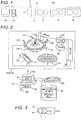
- FIG. 1 is a diagram diagrammatically showing an overall configuration of an automatic analyzer according to the present embodiment
- FIG. 2 is a diagram diagrammatically showing the configuration of an analysis module together with a peripheral configuration of the automatic analyzer.
- an automatic analyzer 100 is roughly constructed of a specimen rack loading portion 21 into which a plurality of types (two types in the present embodiment) of specimen racks 2, 3 (described below) on which the one or more specimen containers 1 (described below) containing a biological sample (hereinafter, called a specimen) such as blood and urine are mounted by the specimen containers 1 being arranged equidistantly in a transport direction thereon is loaded, a transport device 23 that transports the specimen racks 2, 3 to each unit of the automatic analyzer 100, an ID reader 22 that reads and sends ID (identifier: called a specimen rack ID) of the specimen racks 2, 3 transported by the transport device 23 and ID (identifier: called a specimen ID) of the specimen container 1 mounted on the specimen racks 2, 3 to a general management computer 28, analysis modules 24, 25, 26 that analyze a specimen of the specimen container 1 transported by the transport device 23, a specimen rack recovery unit 27 that recovers the specimen racks 2, 3 on which the specimen container 1 for which the analysis by the analysis
- the general management computer 28 include a keyboard 102 and a mouse 103 as operation devices to input or operate various kinds of information, a storage device 107 that stores various kinds of information such as analysis instruction information and measurement results, and a printer 105 to output by printing information.
- the analysis modules 24, 25, 26 are arranged along the transport line 23 and removably connected to the transport line 23. That is, the number of analysis modules in the automatic analyzer 100 can be set to any number and in the present embodiment, a case in which three analysis modules (analysis modules 24, 25, 26) are connected.
- a specimen ID indicating attribute information (such as the paging number, patient name, and request analysis items) about the specimen contained in the specimen container 1 is attached to the specimen container 1 held by being mounted on the specimen racks 2, 3 and further, a rack ID having rack identification information such as a rack number is attached to the specimen racks 2, 3.
- the general management computer 28 determines which of the analysis modules 24, 25, 26 to use for the analysis and the transport device 23 transports the specimen racks 2, 3 to the determined analysis module of the analysis modules 24, 25, 26 so that an analysis operation is performed by the determined analysis module of the analysis modules 24, 25, 26.
- the analysis modules 24, 25, 26 are roughly constructed of an analysis module internal transport device 119 transported by the transport device 23 to transport the specimen racks 2, 3 captured into the analysis modules 24, 25, 26 inside each of the analysis modules 24, 25, 26, a reagent disk 111 on which a plurality of reagent bottles 112 containing a reagent used for analysis of a specimen is mounted, a reaction disk 109 that makes measurements by allowing a specimen and a reagent to react, and a computer 123 connected to each component inside each of the analysis modules 24, 25, 26 via the interface 122 to control an overall operation of each of the analysis modules 24, 25, 26.
- the reaction disk 109 includes a plurality of reaction containers 110 arranged concentrically, a specimen dispensing probe 113 that dispenses a specimen inside the specimen container 1 mounted on the specimen racks 2, 3 transported to a dispensing position of the analysis module internal transport device 119 to the reaction container 110, a reagent dispensing probe 118 that dispenses a reagent in the reagent bottle 112 to the reaction container 110, a stirrer 114 that stirs a mixed solution of a specimen and a reagent after being dispensed to the reaction container 110, a light source 116 that irradiates a reaction solution in the reaction container 110 with a measuring beam, a multiwavelength photometer 117 that detects light that passes through a reaction solution in the reaction container 110 after being irradiated from the light source 116, an A/D converter 124 that makes an analog/digital conversion of a detection signal of the multiwavelength photometer 117 and sends the converted signal to the computer 123 via the interface
- An operator gives an analysis instruction to the automatic analyzer 100 by setting the display apparatus 30 and so on using scanning devices (the keyboard 102 and the mouse 103) of the general management computer 28.
- the analysis instruction is stored in the storage device 107 and also sent to each of the analysis modules 24, 25, 26 via the communication path 106.
- Each of the analysis modules 24, 25, 26 controls the analysis modules 24, 25, 26 in accordance with received analyses as described below. That is, a predetermined amount of specimen contained in the specimen container 1 mounted on the specimen racks 2, 3 transported to the dispensing position to the reaction container 110 by the specimen dispensing probe 113.
- the analysis module internal transport device 119 moves the specimen racks 2,3 such that the next specimen container 1 is directly below (dispensing position) the specimen dispensing probe 113.
- the specimen racks 2, 3 are unloaded by the analysis module internal transport device 119.
- the reaction container 110 to which a specimen is dispensed makes a rotating movement of the reaction disk 109 due to a rotating operation of the reaction disk 109.
- a reagent in the reagent bottle 112 is dispensed to the specimen in the reaction container 110 by the reagent dispensing probe 118, a reaction solution (mixed solution of the specimen and the reagent) is stirred by the stirrer 114, the absorbance of the reaction solution is measured by the light source 116 and the multiwavelength photometer 117, and then, the reaction container 110 for which the analysis is completed is cleaned by the cleaning device 115.
- a measurement signal of the measured absorbance is sent to the computer 123 via the A/D converter 124 and the interface 122.
- the concentration data is sent to the general management computer 28 via the communication path 106 as a measurement result after information obtained by coding the type of specimen is attached.
- the general management computer 28 stores the received measurement result in the storage device 107 and also displays the result in a display apparatus 104 or outputs the result from the printer 105 as printed matter.
- FIGS. 3 to 7 are diagrams diagrammatically showing specimen containers and specimen racks used in the present embodiment.
- FIGS. 3 to 5 are diagrams showing specimen racks on each of which one specimen container is mounted
- FIG. 3 is a top view
- FIG. 4 is a side view
- FIG. 5 is a side view showing a state in which specimen containers are mounted.
- FIGS. 6 and 7 are diagrams showing specimen racks on each of which a plurality of specimen containers is mounted by the specimen containers being arranged equidistantly in the transport direction
- FIG. 6 is a top view showing a state in which specimen containers are mounted
- FIG. 7 is a side view showing a state in which specimen containers are mounted.
- the specimen rack 2 (first specimen rack) on which the one specimen container 1 is mounted includes a base portion 2a formed in a diameter (for example, 30 mm in outside diameter) smaller than that of the transport path (described below) in the transport device 23 and a specimen container holding portion 2b formed above the base portion 2a in a diameter (for example, 24 mm in outside diameter) smaller than that of the base portion 2a to hold the specimen container 1.
- the base portion 2a is formed in a height of, for example, 15 mm and the specimen container holding portion 2b is formed above the base portion 2a in a height of 32 mm. That is, when the specimen racks 2 are arranged on the transport path with the base portions 2a in contact, for example, four specimen racks 2 are arranged, the length thereof is 120 mm and when five specimen racks 2 are arranged, the length thereof is 150 mm.
- the specimen rack 3 (second specimen rack) on which a plurality (five in the present embodiment) of the specimen containers 1 is mounted includes a specimen container holding portion 3b formed to have a width (for example, 20 mm in width) in the transport direction narrower than the specimen container holding portion 2b of the first specimen rack 2 and to be higher (for example, 66 mm in height) than a top end portion of the specimen container holding portion 2b of the first specimen rack 2.
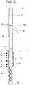
- FIG. 8 is a top view schematically showing main components of a transport device.
- FIG. 9 is a diagram diagrammatically showing the physical relationship between the transport mechanism of the transport device and the transport path when a first specimen rack is transported and
- FIG. 10 is a diagram diagrammatically showing the physical relationship between the transport mechanism of the transport device and the transport path when a second specimen rack is transported.
- the transport device 23 is roughly constructed of belt conveyors 60, 61 longitudinally arranged along the transport path that transports the specimen holders 2, 3 on which the specimen container 1 is mounted, a guide member 63 arranged on both sides of the belt conveyors 60, 61, a rack stopper 64 provided in a specimen rack gripping position 157 arranged on the belt conveyor 60, a plurality of sensors 51 to 56 that detects the presence/absence of the specimen racks 2, 3 in the specimen rack gripping maintenance 157, the transport mechanism 57 that grips the specimen racks 2, 3 in the specimen rack gripping position 157 to transport along the transport path, a rack stopper 65 provided in a specimen dispensing position 162 arranged on the belt conveyor 61, and a dispensing probe 62 that dispenses a specimen from the specimen container 1 mounted on the specimen racks 2, 3 in the specimen dispensing position 162.
- the belt conveyors 60, 61 are driven by a drive mechanism (not shown) such that the specimen racks 2, 3 arranged on the belt conveyors 60, 61 are transported toward the downstream side of the transport path.
- the transport mechanism 57 includes a specimen rack gripping mechanism 59 that grips the specimen racks 2, 3 in the specimen rack gripping position 157 using the gripping plates 57a from both sides of flanks in the transport direction to transport along the transport path and a specimen rack transport mechanism axis drive motor 66 that drives the specimen rack gripping mechanism 59 along the transport path.
- the specimen rack gripping mechanism 59 includes two gripping plates 57a, an arm 58 that holds each of the gripping plates 57a from both sides below, a spring 58a that energizes the arm 58 in the direction of an open state of the gripping plates 57a (that is, in the direction in which the distance between the gripping plates 57a increase), and an opening and closing motor 67 that drives to open or close the gripping plates 57a by driving the arm 58.
- the opening and closing motor 67 is controlled by the general management computer 28 and controls the distance between the gripping plates 57a of the specimen rack gripping mechanism 59 in accordance with the width of the specimen racks 2, 3.
- the guide member 63 includes a first guide member 63a provided along the transport path on both sides of the transport path to guide movement in the transport direction while limiting movement in the width direction of the specimen container holding portion 2b of the first specimen rack 2 and a second guide member 63b provided along the transport path on both sides of the transport path above the top end of the specimen container holding portion 2b of the first specimen rack 2 to guide movement in the transport direction while limiting movement in the width direction of the specimen container holding portion 3a of the second specimen rack 3.
- the present embodiment a configuration having two stages of guide, an upper guide (the second guide member 63b) and a lower guide (the first guide member 63a), is shown, but the present embodiment is not limited to such an example and the guide function of specimen racks may further be improved by providing a plurality of stages of three stages or more by fitting to the shape of the specimen rack that is symmetric with respect to the transport path.
- FIGS. 11 to 13 are diagrams showing the configuration of gripping plates of the transport mechanism
- FIG. 11 is a diagram showing an open state of the gripping plates of the transport mechanism
- FIG. 12 is a diagram showing a closed state in which a first specimen rack is gripped
- FIG. 13 is a diagram showing a closed state in which a second specimen rack is gripped.
- a curved surface portion 70 formed along a side surface shape of the base portion 2a of the first specimen rack 2 and arranged equidistantly in the transport direction and a flat surface portion 71 formed along a side surface shape of the second specimen rack 3 and arranged between curved surface portions in the transport direction are provided on surfaces opposite to each other of the gripping plates 57a.
- the length in the transport direction of the gripping plate 57a is configured to be approximately the same as that of a thinner specimen rack (in the present embodiment, the second specimen rack 3) in the transport direction.
- FIGS. 14 to 16 are diagrams showing a switching structure of the gripping plates 57a in the opening and closing motor 67 of the specimen rack gripping mechanism 59
- FIG. 14 is a diagram showing an open state of the gripping plates 57a
- FIG. 15 is a diagram showing a closed state in which the first specimen rack is gripped
- FIG. 16 is a diagram showing a closed state in which the second specimen rack is gripped.
- a switching mechanism of the specimen rack gripping mechanism 59 includes a disk-shaped member 73a that is driven to rotate in a horizontal direction by the opening and closing motor 67 using the middle in the transport direction and the width direction of the transport path of the gripping plate 57a as a rotation center, a sliding protrusion 73b provided on the surface on the side of the gripping plate 57a in two positions symmetric with respect to the center of the disk-shaped member 73a, a longitudinal guide 73c provided on the gripping plate 57a along the transport path to guide movement in the transport direction of the sliding protrusion 73b, and a transverse guide 73d that guides movement in the width direction of the transport path of the gripping plate 57a.
- the first specimen rack 2 and the second specimen rack 3 are gripped by the gripping plates 57a by the disk-shaped member 73a being driven to rotate by the opening and closing motor 67 from an open state (see FIG. 14 ) in which the specimen racks 2, 3 are released from the gripping plates 57a of the transport mechanism 57 and the gripping plate 57a having the longitudinal guide 73c that guides movement of the sliding protrusion 73b being moved in the width direction of the transport path while being guided by the transverse guide 73d with an approaching relative position of the sliding protrusion 73b in the width direction of the transport path (see FIGS. 15 and 16 ). That is, the gripping plate 57a can be driven to open or close by changing the rotating direction of the opening and closing motor 67. Also, by changing the rotation angle of the disk-shaped member 73a by the opening and closing motor 67, the distance (opening and closing distance) between the gripping plates 57a can be controlled.
- FIGS. 17 and 18 are diagrams showing the physical relationship between each sensor and the specimen rack in the specimen rack gripping position
- FIG. 17 is a diagram showing an example in which four first specimen racks are stopped in the specimen rack gripping position by a rack stopper
- FIG. 18 is a diagram showing an example in which a second specimen rack is stopped.
- the sensors 51 to 56 are arranged so as to detect the presence/absence of the specimen racks 2, 3 in the center position of the No. 1 first specimen rack 2 (sensor 51), the position between the No. 1 and No. 2 first specimen racks 2 (sensor 52), the center position of the No. 2 first specimen rack 2 (sensor 53), the center position of the No. 3 first specimen rack 2 (sensor 54), the center position of the No. 4 first specimen rack 2 (sensor 55), and the position of the upstream end of the No. 4 first specimen rack 2 (sensor 56) in the order from the downstream side of the transport path.
- an output signal (specimen rack presence/absence information) is ON when the specimen racks 2, 3 are detected in each position and the output signal (specimen rack presence/absence information) is OFF when the specimen racks 2, 3 are not detected.
- specimen rack presence/absence information obtained from the sensors 51 to 56 which of the specimen racks 2, 3 is present in the specimen rack gripping position 157 can be determined and thus, a plurality of specimen racks having different widths can be determined.
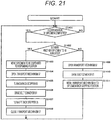
- FIGS. 19 to 21 are flow charts showing the flow of a transport process of a specimen rack by a transport device
- FIG. 19 is a flow chart showing a specimen rack transport request process of the transport process
- FIG. 20 is a flow chart showing a specimen rack movement process of the transport process
- FIG. 21 is a flow chart showing a specimen dispensing process of the transport process.
- the general management computer 28 first determines whether the transport mechanism 57 is in a standby state (state of not being driven) (step S1101) and if the determination result is NO, repeats the determination in step S1101 1 until the determination result becomes YES. If the determination result in step S1101 is YES, the general management computer 28 turns on the rack stopper 64 to block movement of the specimen racks 2, 3 on the belt conveyor 60 (step S1102) and drives the belt conveyor 60 (step S1103). Subsequently, the general management computer 28 determines whether the sensor 51 is ON (step S1104) and if the determination result is NO, determines whether a preset transport mechanism standby time has passed (step S1107).
- step S1107 determines whether the transport mechanism 57 is waiting in the specimen rack gripping position 157 (step S1104). If the determination result in step S1105 is YES, the general management computer 28 issues a specimen rack transport request to transport the specimen racks 2, 3 in the specimen rack gripping position 157 to the transport mechanism 57 (step S1106) and then, returns to the process in step S1101. If the determination result in step S1106 is NO, the general management computer 28 repeats the determination in step S1106 until the determination result becomes YES.
- FIG. 22 is a diagram showing a setting screen to set a transport mechanism standby time in the specimen rack transport request process.
- a setting screen 12 of the transport mechanism standby time is displayed in the display apparatus 30 and set by an operation using operating device (the keyboard 102, the mouse 103) and includes an input unit 13 of the standby time, a cancel button 14 to cancel input, and an OK button 15 to confirm the input result.
- the standby time of the transport mechanism 57 is input into the input unit 12 by operating devices and confirmed by an operation of the OK button 15.
- the general management computer 28 first determines whether the transport mechanism 57 is waiting in the specimen rack gripping position 157 (step S1301) and if the determination result is YES, determines whether a specimen rack transport request has been issued in the specimen rack transport request process (step S1302).
- step S1302 determines whether the determination result in step S1302 is NO, the general management computer 28 repeats the determination in step S1301 and if the determination result is YES, the general management computer 28 releases movement of the specimen racks 2, 3 on the belt conveyor 60 by turning off the rack stopper 64 to determine whether the specimen rack in the specimen rack gripping position 157 is the specimen rack 2 (first specimen rack) on which the one specimen container 1 is mounted or the specimen rack 3 (second specimen rack) on which a plurality (five) of the specimen containers 1 is mounted (step S1304).
- step S1304 the general management computer 28 closes the gripping plates 57a of the transport mechanism 57 such that the distance between the gripping plates 57a becomes the width of the first specimen rack 2 (step S1305) and moves the transport mechanism 57 to the specimen dispensing position 162 (step S1307) before returning to the process in step S1301.
- the general management computer 28 closes the gripping plates 57a of the transport mechanism 57 such that the distance between the gripping plates 57a becomes the width of the second specimen rack 3 (step S1306) and moves the transport mechanism 57 to the specimen dispensing position 162 (step S1307) before returning to the process in step S1301.
- step S1301 determines whether the transport mechanism 57 is waiting in the specimen dispensing position 162 (step S1308) and if the determination result is YES, creates a specimen dispensing schedule for the transport mechanism 57 before returning to the determination in step S1301. Also, if the determination result in step S1308 is NO, the general management computer 28 returns to the determination in step S1301.
- the general management computer 28 first determines whether dispensation of the specimen in the specimen container 1 mounted on the specimen racks 2, 3 in the specimen dispensing position 162 is completed (step S1401) and if the determination result is NO, repeats the process in step S1401 until the determination result becomes YES.
- step S1401 determines whether the specimen to be dispensed is contained in the other specimen containers 1 mounted on the specimen racks 2, 3 (step S1402) and if the determination result is YES, moves the specimen container 1 to be dispensed to the dispensing position (step S1403), puts the transport mechanism 57 to an open state (step S1404), blocks movement of the specimen racks 2, 3 on the transport path by turning on the rack stopper 65 (step S1405), releases and transports only the specimen racks 2, 3 on which the specimen container 1 whose dispensation is completed is mounted from the transport mechanism 57 to the next analysis module by driving the belt conveyor 61 (step S1406), opens the transport path by turning off the rack stopper 65 (step S1407), and puts the transport mechanism 57 to a closed state (step S1408) before returning to the determination in step S1401.
- step S1402 If the determination result in step S1402 is NO, the general management computer 28 puts the transport mechanism 57 to an open state (step S1409), drives the belt conveyor 61 (step S1410), and moves the transport mechanism 57 to the specimen rack gripping position 157 (step S1411) before returning to the determination in step S1401.
- FIGS. 23 to 30 are diagrams diagrammatically showing states of the gripping operation and transport operation of the specimen racks 2, 3 in the specimen rack gripping position 157.
- FIG. 23 is a diagram showing a state in which the four specimen racks 2 (first specimen racks) or more, each of which having the one specimen container 1 mounted thereon, are successively stopped by the rack stopper 64 in the specimen rack gripping position 157 and
- FIG. 24 is a diagram showing a state in which the four first specimen racks 2 on the downstream side are gripped by the transport mechanism 57 and transported downstream.
- specimen racks stopped in the specimen rack gripping position 157 are all determined to be the specimen racks 2 and the specimen racks 2 are gripped by determining the gripping width between the gripping plates 57a of the transport mechanism 57 by fitting to the width of the specimen rack 2 and setting a closed state.
- the rack stopper 64 is driven to be turned off and the belt conveyor 60 is released so that only the four specimen racks 2 gripped by the transport mechanism 57 are transported on the belt conveyor 61 on the downstream side.
- FIG. 25 is a diagram showing a state in which a plurality of the specimen racks 3 (second specimen racks), each of which having a plurality (five) of the specimen containers 1 mounted thereon, is successively stopped by the rack stopper 64 in the specimen rack gripping position 157
- FIG. 26 is a diagram showing a state in which the second specimen rack 3 on the downstream side is gripped by the transport mechanism 57 and transported downstream.
- the specimen rack stopped in the specimen rack gripping position 157 is determined to be the specimen rack 3 (second specimen rack) and the specimen rack 3 is gripped by determining the gripping width between the gripping plates 57a of the transport mechanism 57 by fitting to the width of the specimen rack 3 and setting a closed state.
- the rack stopper 64 is driven to be turned off and the belt conveyor 60 is released so that the specimen rack 3 gripped by the transport mechanism 57 is transported on the belt conveyor 61 on the downstream side.
- FIG. 27 is a diagram showing a state in which the specimen rack 2 (first specimen rack) having the one specimen container 1 mounted thereon and the specimen rack 3 (second specimen rack) having a plurality (five) of the specimen containers 1 mounted thereon are successively stopped by the rack stopper 64 in the specimen rack gripping position 157 and
- FIG. 28 is a diagram showing a state in which only the most downstream first specimen rack 2 is gripped by the transport mechanism 57 and transported downstream.
- the rack stopper 64 is driven to be turned off and the belt conveyor 60 is released so that only the specimen rack 2 at the head gripped by the transport mechanism 57 is transported on the belt conveyor 61 on the downstream side and the second specimen rack having a width narrower than that of the first specimen rack remains there. If three first specimen racks or less are arranged successively from the head, the first specimen racks arranged successively are all transported downstream and the succeeding second specimen rack remains.
- FIG. 29 is a diagram showing a state in which the specimen rack 3 (second specimen rack) having a plurality (five) of the specimen containers 1 mounted thereon and the specimen rack 2 (first specimen rack) having the one specimen container 1 mounted thereon are successively stopped by the rack stopper 64 in the specimen rack gripping position 157 and
- FIG. 30 is a diagram showing a state in which only the most downstream second specimen rack 3 is gripped by the transport mechanism 57 and transported downstream.
- the specimen rack 3 (second specimen rack) and the specimen racks 2 (first specimen racks) are successively stopped in the specimen rack gripping position 157, output signals (specimen rack presence/absence information) obtained from the sensors 51, 52 are ON, ON respectively and output signals (specimen rack presence/absence information) obtained from the sensors 55, 56 are ON, ON respectively.
- the specimen rack stopped most downstream in the specimen rack gripping position 157 is determined to be the specimen rack 3 (second specimen rack) and the specimen rack 3 is gripped by determining the gripping width between the gripping plates 57a of the transport mechanism 57 by fitting to the width of the specimen rack 3 and setting a closed state.
- the rack stopper 64 is driven to be turned off and the belt conveyor 60 is released so that only the specimen rack 3 gripped by the transport mechanism 57 is transported on the belt conveyor 61 on the downstream side and the subsequent first specimen racks that are not gripped by the transport plates 57a remain there.
- one or a plurality of specimen containers may be mounted on a specimen rack and transported and when a plurality of types of specimen racks in different shapes is transported, a transport line is needed for each type (shape) of specimen rack, which poses a problem that the structure and control of the automatic analyzer become more complicated, leading to an increase in size of the apparatus and also an increase in cost.
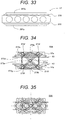
- FIGS. 31 to 33 are diagrams showing the configuration of gripping plates of the transport mechanism in the present modification
- FIG. 31 is a diagram showing an open state of the gripping plates of the transport mechanism
- FIG. 32 is a diagram showing a closed state in which the first specimen rack is gripped
- FIG. 33 is a diagram showing a closed state in which the second specimen rack is gripped.
- an elastic body that is deformed by fitting to the shape of the side surface of the first specimen rack 2 or the second specimen rack 3 is arranged on surfaces opposite to each other of gripping plates 257a in the present modification.
- the length in the transport direction of the gripping plate 257a is configured to be approximately the same as that of a thinner specimen rack (in the present embodiment, the second specimen rack 3) in the transport direction.
- the surfaces opposite to each other of the gripping plates 257a are flat surfaces, but when the first specimen rack 2 is gripped by the gripping plates 257a by the gripping plates 257a being changed to a closed state (see FIG. 32 ), the first specimen rack 2 is sandwiched by the shape of the gripping plates 257a being deformed into a curved surface by fitting to the shape of the side surface of the base portion 2a of the first specimen rack 2 so that the first specimen rack 2 is held in a stable manner. Also, as shown in FIG.
- the other configuration is the same as in the first embodiment.
- FIGS. 34 to 36 are diagrams showing a switching structure of the gripping plate 57a in the opening and closing motor 67 of the specimen rack gripping mechanism 59 according to the present modification
- FIG. 34 is a diagram showing an open state of the gripping plates 57a
- FIG. 35 is a diagram showing a closed state in which the first specimen rack is gripped
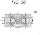
- FIG. 36 is a diagram showing a closed state in which the second specimen rack is gripped.
- a switching mechanism of a specimen rack gripping mechanism 59A includes a disk-shaped member 273a that is driven to rotate in a horizontal direction by the opening and closing motor 67 using the middle in the transport direction and the width direction of the transport path of the gripping plate 57a as a rotation center, a sliding protrusion 273b provided on the surface on the side of the gripping plate 57a in two positions symmetric with respect to the center of the disk-shaped member 73a, a longitudinal guide 273c provided on the gripping plate 57a along the transport path to guide movement in the transport direction of the sliding protrusion 273b, a transverse guide 273d that guides movement in the width direction of the transport path of the gripping plate 57a, and two bar members 273g rotatably provided around a center 273e of the disk-shaped member 273a.
- the two bar members 273g having the same length are arranged so as to cross in the center 273e of the disk-shaped member 273a in the center portion thereof and a sliding protrusion 273f that moves along the longitudinal guide 273c of the gripping plate 57a is provided on both ends of each.
- the first specimen rack 2 and the second specimen rack 3 are gripped by the gripping plates 57a by the disk-shaped member 273a being driven to rotate by the opening and closing motor 67 from an open state (see FIG. 34 ) in which the specimen racks 2, 3 are released from the gripping plates 57a of the transport mechanism 57 and the gripping plate 57a having the longitudinal guide 273c that guides movement of the sliding protrusion 273b being moved in the width direction of the transport path while being guided by the transverse guide 273d with an approaching relative position of the sliding protrusion 273b in the width direction of the transport path (see FIGS. 35 and 36 ).
- parallel properties of the gripping plates 57a are maintained by the two bar members 273g.
- the gripping plate 57a can be driven to open or close by changing the rotating direction of the opening and closing motor 67. Also, by changing the rotation angle of the disk-shaped member 273a by the opening and closing motor 67, the distance (opening and closing distance) between the gripping plates 57a can be controlled.
- the other configuration is the same as in the first embodiment.
- FIGS. 37 to 49 A second embodiment of the present invention will be described with reference to FIGS. 37 to 49 .
- the same reference signs are attached to members similar to those in the first embodiment and a description thereof is omitted.
- FIG. 1 is a diagram diagrammatically showing an overall configuration of an automatic analyzer according to the present embodiment
- FIG. 2 is a diagram diagrammatically showing the configuration of an analysis module together with a peripheral configuration of the automatic analyzer.
- FIG. 37 is a top view schematically showing main components of a transport device according to the present embodiment.
- FIG. 38 is a diagram diagrammatically showing the configuration of the transport mechanism of the transport device when a first specimen rack is transported and
- FIG. 39 is a diagram diagrammatically showing the configuration of the transport mechanism of the transport device when a second specimen rack is transported.
- a transport device 323 is roughly constructed of belt conveyors 60, 61 longitudinally arranged along a transport path that transports specimen holders 2, 3 on which a specimen container 1 is mounted, a specimen rack transport path 360 longitudinally connected between the belt conveyors 60, 61, a rack stopper 64 provided in a specimen rack gripping position 157 arranged on the belt conveyor 60, a plurality of sensors 51 to 56 that detects the presence/absence of the specimen racks 2, 3 in the specimen rack gripping maintenance 157, a transport mechanism 57 that grips the specimen racks 2, 3 in the specimen rack gripping position 157 to transport along a specimen rack transport path 363, belt conveyors 368, 369 longitudinally arranged along the specimen rack transport path 360 as a second transport path, guide members 63, 363 arranged on both sides of the belt conveyors 60, 61, 368, 369 and the specimen rack transport path 360, rack stoppers 372 to 375 provided on the belt conveyor 368, a retracting transport mechanism 376
- the belt conveyors 60, 61, 368, 369 are driven by a drive mechanism (not shown) such that the specimen racks 2, 3 arranged on the belt conveyors 60, 61 are transported toward the downstream side of the transport path.
- the transport mechanism 57, 377 includes a specimen rack gripping mechanism 59 that grips the specimen racks 2, 3 in the specimen rack gripping position 157 using the gripping plates 57a from both sides of flanks in the transport direction to transport along the transport path and a specimen rack transport mechanism axis drive motor 66 that drives the specimen rack gripping mechanism 59 along the transport path.
- the specimen rack gripping mechanism 59 includes two gripping plates 57a, an arm 58 that holds each of the gripping plates 57a from both sides below, a spring 58a that energizes the arm 58 in the direction of an open state of the gripping plates 57a (that is, in the direction in which the distance between the gripping plates 57a increases), and an opening and closing motor 67 that drives to open or close the gripping plates 57a by driving the arm 58.
- the opening and closing motor 67 is controlled by a general management computer 28 and controls the distance between the gripping plates 57a of the specimen rack gripping mechanism 59 in accordance with the width of the specimen racks 2, 3.
- the retracting transport mechanisms 376A, 376B include a specimen rack gripping mechanism 359 that grips the specimen racks 2, 3 using the gripping plates 357a from both sides of flanks in the transport direction to transport along the transport path and a specimen rack transport mechanism axis drive motor 380 that drives the specimen rack gripping mechanism 359 in a direction along the transport path and the width direction.
- the specimen rack gripping mechanism 359 includes two gripping plates 357a, an arm 376 that holds each of the gripping plates 357a from both sides above, a spring 376a that energizes the arm 376 in the direction of an open state of the gripping plates 357a (that is, in the direction in which the distance between the gripping plates 357a increases), and an opening and closing motor 380 that drives to open or close the gripping plates 357a by driving the arm 376.
- the opening and closing motor 380 is controlled by the general management computer 28 and controls the distance between the gripping plates 357a of the specimen rack gripping mechanism 359 in accordance with the width of the specimen racks 2, 3.
- the guide member 63, 363 includes a first guide member 63a provided along the transport path on both sides of the transport path to guide movement in the transport direction while limiting movement in the width direction of the specimen container holding portion 2b of the first specimen rack 2 and a second guide member 63b provided along the transport path on both sides of the transport path above the top end of the specimen container holding portion 2b of the first specimen rack 2 to guide movement in the transport direction while limiting movement in the width direction of the specimen container holding portion 3a of the second specimen rack 3.
- the present embodiment a configuration having two stages of guide, an upper guide (the second guide member 63b) and a lower guide (the first guide member 63a), is shown, but the present embodiment is not limited to such an example and the guide function of specimen racks may further be improved by providing a plurality of stages of three stages or more by fitting to the shape of the specimen rack to be transport symmetric.
- FIGS. 40 and 41 are diagrams showing the configuration of gripping plates of a retracting transport mechanism
- FIG. 40 is a diagram showing an open state of the gripping plates of the transport mechanism
- FIG. 41 is a diagram showing a closed state in which a first specimen rack is gripped.
- the gripping plate 357a has a configuration approximately the same as that of the gripping plate 57a and a curved surface portion 390 formed along a side surface shape of a specimen container holding portion 2b of the first specimen rack 2 and arranged equidistantly in the transport direction and a flat surface portion 391 formed along a side surface shape of the second specimen rack 3 and arranged between curved surface portions in the transport direction are provided on surfaces opposite to each other of the gripping plates 357a.
- the length in the transport direction of the gripping plate 357a is configured to be approximately the same as that of a thinner specimen rack (in the present embodiment, the second specimen rack 3) in the transport direction.
- FIGS. 42 to 49 are flow charts showing the flow of the transport process of a specimen rack by a transport device according to the present embodiment.
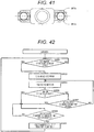
- FIG. 42 is a flow chart diagrammatically showing a specimen rack transport request process of the transport process.
- the general management computer 28 first determines whether the transport mechanism 57 is in a standby state (state of not being driven) (step S2001) and if the determination result is NO, repeats the determination in step S2001 until the determination result becomes YES. If the determination result in step S2001 is YES, the general management computer 28 turns on the rack stopper 64 to block movement of the specimen racks 2, 3 on the belt conveyor 60 (step S2002) and drives the belt conveyor 60 (step S2003). Subsequently, the general management computer 28 determines whether the sensor 51 is ON (step S2004) and if the determination result is ON, determines whether a preset transport mechanism standby time has passed (step S2007).
- step S2007 If the determination result in step S2007 is NO, the general management computer 28 returns to the process in step S2003. If the determination result in step S2004 is YES or the determination result in step S2007 is YES, the general management computer 28 determines whether the transport mechanism 57 is waiting in the specimen rack gripping position 157 (step S2004). If the determination result in step S2005 is YES, the general management computer 28 issues a specimen rack transport request to transport the specimen racks 2, 3 in the specimen rack gripping position 157 to the transport mechanism 57 (step S2006) and then, returns to the process in step S2001. If the determination result in step S2006 is NO, the general management computer 28 repeats the determination in step S2006 until the determination result becomes YES.
- FIG. 43 is a flow chart diagrammatically showing a transport mechanism movement process of the transport process.
- the general management computer 28 first determines whether the transport mechanism 57 is waiting in the receiving position of the specimen racks 2, 3 (step S2301) and if the determination result is YES, turns off the rack stopper 64 (step S2302) and closes the transport mechanism 57 to hold the specimen racks 2, 3 (step S2303).
- the general management computer 28 determines whether the retracting transport mechanism 376A is waiting (step S2304) and if the determination result is NO, waits until the determination result becomes YES and if the determination result is YES, moves the transport mechanism 57 to a retracting position (step S2305) and issues a movement request of the retracting transport mechanism 376A (step S2306) before returning to the process in step S2301. If the determination result in step S2301 is NO, the general management computer 28 determines whether the transport mechanism 57 is waiting in the retracting position (step S2307) and determines whether any movement request to the receiving position of the transport mechanism 57 has been issued (step S2308).
- the general management computer 28 returns to the process of step S2301 if the determination result of step S2307 or S2308 is NO and moves the transport mechanism 57 to the receiving position (step S2309) before returning to the process in step S2301 if the determination results of both steps S2307, S2308 are YES.
- FIG. 44 is a flow chart diagrammatically showing a retracting transport mechanism movement process of the transport process.
- the general management computer 28 first determines whether the retracting transport mechanism 376A is waiting (step S2401) and determines whether an operation request has been issued to the retracting transport mechanism 376A (step S2402). If the determination result one of steps S2401, S2402 is NO, the general management computer 28 repeats the processes in steps S2401, S2402 until both determination results become YES. If the determination results of both steps S2401, S2402 are YES, the general management computer 28 closes the retracting transport mechanism 376A (step S2403), open the transport mechanism 57 (step S2404), and issues a movement request to the receiving position to the transport mechanism 57 (step S2405).
- the general management computer 28 determines whether the transport mechanism 57 is in a standby state in the receiving position (step S2406) and if the determination result is NO, repeats the process in step S2406. If the determination result in step S2406 is YES, the general management computer 28 opens the shutter 366 (step S2407), moves the retracting transport mechanism 376A to the belt conveyor 368 (step S2408), opens the retracting transport mechanism 376A (step S2409), and issue an operation request of the belt conveyor 368 (step S2410).
- the general management computer 28 determines whether a movement request to the receiving position of the retracting transport mechanism 376A has been issued (S2411) and if the determination result is NO, repeats the determination process in step S2411. If the determination result in step S2411 is YES, the general management computer 28 moves the retracting transport mechanism 376A to the standby position (step S2412) before returning to the process in step S2401.
- FIG. 45 is a flow chart diagrammatically showing a belt conveyor drive process of the transport process.
- the general management computer 28 first determines whether any operation request of the retracting transport mechanism 376A has been issued (step S2501) and if the determination result is NO, repeats the process in step S2501. If the determination result in step S2501 is YES, the general management computer 28 opens the rack stopper 372 and closes the rack stopper 373 (step S2502). Subsequently, the general management computer 28 drives the belt conveyor 368 (step S2503) and reads the specimen identifier (specimen ID) of the specimen container 1 (step S2504).
- the general management computer 28 determines whether the transport mechanism 377 is waiting in the specimen dispensing position 362a (step S2505) and if the determination result is NO, repeats the process in step S2505. If the determination result in step S2505 is YES, the general management computer 28 opens the rack stoppers 373, 374 and also closes the rack stopper 375 (step S2507) and drives the belt conveyor 368 (step S2508). Subsequently, the general management computer 28 determines whether the specimen racks 2, 3 of the retracting transport mechanism 376A have all been unloaded (S2508) and if the determination result is NO, returns to the process in step S2502.
- step S2508 If the determination result in step S2508 is YES, the general management computer 28 issues a movement request to the receiving position to the retracting transport mechanism 376A (step S2509) and issues a movement request to the receiving position to the transport mechanism 377 (step S2510) before returning to the process in step S2502.
- FIG. 46 is a flow chart diagrammatically showing a belt conveyor drive process of the transport process.
- the general management computer 28 first determines whether the transport mechanism 377 is waiting in a delivery position (step S2601) and if the determination result is YES, determines whether an operation request of the belt conveyor 368 has been issued (step S2602). If the determination result in step S2602 is NO, the general management computer 28 repeats the process in step S2602. If the determination result in step S2602 is YES, the general management computer 28 opens the rack stopper 375 (step S2603), closes the transport mechanism 377 (step S2604), and moves the transport mechanism 377 to the specimen dispensing position 362a (step S2605) before returning to the process in step S2601.
- step S2601 determines whether the transport mechanism 377 is waiting in the dispensing position (step S2606) and if the determination result is NO, returns to the process in step S2601. If the determination result in step S2606 is YES, the general management computer 28 creates a specimen dispensing position schedule (step S2607) before returning to the process in step S2601.
- FIG. 47 is a flow chart diagrammatically showing a transport mechanism drive process in the dispensing position of the transport process.
- the general management computer 28 In the transport mechanism drive process in the dispensing position of the transport process, as shown in FIG. 47 , the general management computer 28 first determines whether the transport mechanism 377 is in a standby state (step S2701) and if the determination result is NO, repeats the process in step S2701. If the determination result in step S2701 is YES, the general management computer 28 determines whether the dispensing process of the specimen container 1 is completed (step S2702) and if the determination result is NO, repeats the process in step S2702.
- step S2703 determines whether there is any other specimen to be dispensed (that is, a specimen to be analyzed) (step S2703) and if the determination result is YES, calculates a moving distance in accordance with the specimen container fixed by the transport mechanism 377 (step S2714) and moves the specimen container 1 containing the specimen to be analyzed to the dispensing position 362a in accordance with the calculation result in step S2714 (step S2704) before returning to the process in step S2701. If the determination result in step S2703 is NO, the general management computer 28 opens the transport mechanism 57 (step S2705) and determines whether the retracting transport mechanism 376B is in a standby state (step S2706).
- step S2706 If the determination result in step S2706 is NO, the general management computer 28 repeats the process in step S2706. If the determination result in step S2706 is YES, the general management computer 28 drives the belt conveyor 369 (step 2707), issues an operation request of the retracting transport mechanism 376B (step S2708), and moves the transport mechanism 377 to the receiving position of the specimen racks 2, 3 (step S2709) before returning to the process in step S2701.
- FIG. 48 is a flow chart diagrammatically showing a retracting transport mechanism drive process of the transport process.
- the general management computer 28 first determines whether the retracting transport mechanism 376B is in a standby state (step S2801) and if the determination result is NO, repeats the process in step S2801. If the determination result in step S2801 is YES, the general management computer 28 determines whether any unload request of the specimen racks 2, 3 has been issued (step S2802) and if the determination result is NO, repeats the process in step S202.
- step S2803 the general management computer 28 closes the retracting transport mechanism 376B (step S2803), opens the shutter 367 (step S2804), moves the retracting transport mechanism 376B to an unloading position (step S2805), opens the retracting transport mechanism 376B (step S2806), transports the specimen rack to the next analysis module by driving the belt conveyor 61 (step S2807), moves the retracting transport mechanism 376B to the receiving position (step S2808), and closes the shutter 367 (step S2809) before terminating the process.
- steps S2802, S2803 information that allows to determine the shape of the specimen rack is received together with any operation request received from the belt conveyor 61 and the specimen rack is fixed by determining the gripping width fitting to the shape of the specimen rack and closing the retracting transport mechanism 376B.
- FIG. 49 is a flow chart diagrammatically showing an analysis process.
- the general management computer 28 first determines whether the specimen be analyzed is an urgent specimen (step S2901) and if the determination result is YES, determines whether dispensation of the specimen is completed (step S2903). If the determination result in step S2903 is NO, the general management computer 28 repeats the process in step S2903.
- step S2904 determines whether there is any other specimen to be analyzed (step S2904) and if the determination result is YES, moves the specimen to be analyzed to the dispensing position (step S2905), opens the transport mechanism 57 (step S2906), turns on the rack stopper 459 (step S2907), drives the belt conveyor 61 (step S2908), turns off the rack stopper 459 (step S2909), and closes the transport mechanism 57 (step S2910) before returning to the process in step S2901.
- step S2904 If the determination result in step S2904 is NO, the general management computer 28 opens the transport mechanism 57 (step S2911), drives the belt conveyor 61 (step S2912), and moves the transport mechanism 57 to the receiving position of the specimen rack (step S2913) before terminating the process. If the determination result in step S2901 is NO, the general management computer 28 determines whether there is any subsequent urgent specimen (step S2902) and if the determination result is YES, proceeds to the process in step S2905 and if the determination result is NO, proceeds to the process in step S2903.
- the other configuration is the same as in the first embodiment.
- the present modification shows a case when the transport direction of the specimen racks 2, 3 is changed by a retracting transport mechanism 476.
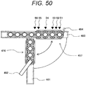
- FIG. 50 is a diagram diagrammatically showing the configuration of the transport device in a retracting position of the specimen rack.
- the same reference signs are attached to members similar to those in the second embodiment and a description thereof is omitted.
- a rack stopper 464 that blocks movement of the specimen racks 2, 3, a belt conveyor 461 that transports the specimen racks 2, 3 in a direction different from that of a belt conveyor 460, the retracting transport mechanism 476 that transports the specimen racks 2, 3 from the belt conveyor 460 to the belt conveyor 461, a dispensing probe 462 that dispenses the specimen of the specimen container 1 of the specimen racks 2, 3 on the belt conveyor 461, and the sensors 51 to 56 are arranged in a retracting position 457 of the specimen racks 2, 3 provided on the belt conveyor 460.
- the retracting transport mechanism 476 changes the direction of the specimen racks 2, 3 by matching to the belt conveyor 461 from the belt conveyor 460.
- the other configuration is the same as in the second embodiment.
Landscapes
- Engineering & Computer Science (AREA)
- General Health & Medical Sciences (AREA)
- Life Sciences & Earth Sciences (AREA)
- Chemical & Material Sciences (AREA)
- Analytical Chemistry (AREA)
- Biochemistry (AREA)
- Physics & Mathematics (AREA)
- General Physics & Mathematics (AREA)
- Immunology (AREA)
- Pathology (AREA)
- Health & Medical Sciences (AREA)
- Robotics (AREA)
- Mechanical Engineering (AREA)
- Automatic Analysis And Handling Materials Therefor (AREA)
Abstract
Description
- Embodiments described herein relate generally to an automatic analyzer that conducts a qualitative/quantitative analysis of a biological sample such as blood and urine contained in a specimen container.
- An automatic analyzer is known as an apparatus that automatically conducts a qualitative/quantitative analysis of a biological sample (hereinafter, called a specimen) such as blood and urine and in large hospitals and clinical examination centers where many patients' specimens need to be processed in a short time, various kinds of automatic analyzers, from small to large apparatuses, are used in accordance with necessary processing capabilities.
- In such an automatic analyzer, various kinds of processes is performed by using specimen containers containing specimens and particularly in a large automatic analyzer, it is necessary to handle a huge amount of specimen containers and various technologies have been developed to make the analysis more efficient.
- For example, PTL 1 (
JP 2004-61136 A - PTL 1:
JP 2004-61136 A - In an automatic analyzer, by the way, one or a plurality of specimen containers may be mounted on a specimen rack and transported and when a plurality of types of specimen racks in different shapes is transported, a transport line is needed for each type (shape) of specimen rack, which poses a problem that the structure and control of the automatic analyzer become more complicated, leading to an increase in size of the apparatus and also an increase in cost.
- The present invention is made in view of the above circumstances and an object thereof is to provide an automatic analyzer capable of transferring a plurality of types of specimen racks while suppressing an increase in size of the apparatus and also an increase in cost.
- To achieve the above object, the present invention is an automatic analyzer having a transport device that transports a specimen rack on which one or more specimen containers containing a specimen to be analyzed are mounted by the specimen containers being arranged equidistantly in a transport direction and an analysis unit that analyzes the specimen contained in the specimen container, wherein the transport device includes a specimen rack gripping mechanism that grips the specimen rack on a first transport path on which the specimen rack is transported by the specimen rack being sandwiched between gripping plates from both sides of flanks in the transport direction to transport the specimen rack along the first transport path and a gripping width controller that controls a distance between the gripping plates of the specimen rack gripping mechanism in accordance with a width of the specimen rack.
- A plurality of types of specimen racks can be transported while an increase in size of the apparatus and also an increase in cost are suppressed.
-
- [
FIG. 1] FIG. 1 is a diagram diagrammatically showing an overall configuration of an automatic analyzer according to a first embodiment. - [
FIG. 2] FIG. 2 is a diagram diagrammatically showing the configuration of an analysis module together with a peripheral configuration of the automatic analyzer. - [
FIG. 3] FIG. 3 is a diagram diagrammatically showing a specimen container and a specimen rack and a top view showing a specimen rack on which one specimen container is mounted. - [
FIG. 4] FIG. 4 is a diagram diagrammatically showing the specimen container and the specimen rack and a side view showing the specimen rack on which one specimen container is mounted. - [
FIG. 5] FIG. 5 is a diagram diagrammatically showing the specimen container and the specimen rack and a side view showing a state in which a specimen container is mounted on the specimen rack on which one specimen container is mounted. - [
FIG. 6] FIG. 6 is a diagram showing the specimen rack on which a plurality of specimen containers is mounted by the specimen containers being arranged equidistantly in a transport direction and a top view showing a state in which the specimen containers are mounted. - [
FIG. 7] FIG. 7 is a diagram showing the specimen rack on which the plurality of specimen containers is mounted by the specimen containers being arranged equidistantly in the transport direction and a side view showing a state in which the specimen containers are mounted. - [
FIG. 8] FIG. 8 is a top view schematically showing main components of a transport device. - [
FIG. 9] FIG. 9 is a diagram diagrammatically showing a physical relationship between a transport mechanism of the transport device and a transport path when transporting a first specimen rack. - [
FIG. 10] FIG. 10 is a diagram diagrammatically showing the physical relationship between the transport mechanism of the transport device and the transport path when transporting a second specimen rack. - [
FIG. 11] FIG. 11 ] is a diagram showing the configuration of a gripping plate of the transport mechanism and a diagram showing an open state of the gripping plates of the transport mechanism. - [
FIG. 12] FIG. 12 is a diagram showing the configuration of the gripping plate of the transport mechanism and a diagram showing a closed state in which the first specimen rack is gripped. - [
FIG. 13] FIG. 13 is a diagram showing the configuration of the gripping plate of the transport mechanism and a diagram showing a closed state in which the second specimen rack is gripped. - [
FIG. 14] FIG. 14 is a diagram showing a switching structure of the gripping plate in an opening and closing motor of a specimen rack gripping mechanism and a diagram showing an open state of the gripping plates. - [
FIG. 15] FIG. 15 is a diagram showing the switching structure of the gripping plate in the opening and closing motor of the specimen rack gripping mechanism and a diagram showing a closed state in which the first specimen rack is gripped. - [
FIG. 16] FIG. 16 is a diagram showing the switching structure of the gripping plate in the opening and closing motor of the specimen rack gripping mechanism and a diagram showing a closed state in which the second specimen rack is gripped. - [
FIG. 17] FIG. 17 is a diagram showing the physical relationship between each sensor and the specimen rack in a specimen rack gripping position and a diagram showing an example in which four first specimen racks are stopped in the specimen rack gripping position by a rack stopper. - [
FIG. 18] FIG. 18 is a diagram showing the physical relationship between each sensor and the specimen rack in the specimen rack gripping position and a diagram showing an example in which the second specimen rack is stopped. - [
FIG. 19] FIG. 19 is a flow chart showing the flow of a transport process of the specimen rack by the transport device and a flow chart showing a specimen rack transport request process of the transport process. - [
FIG. 20] FIG. 20 is a flow chart showing the flow of the transport process of the specimen rack by the transport device and a flow chart showing a specimen rack movement process of the transport process. - [
FIG. 21] FIG. 21 is a flow chart showing the flow of the transport process of the specimen rack by the transport device and a flow chart showing a specimen dispensing process of the transport process. - [
FIG. 22] FIG. 22 is a diagram showing a setting screen to set a transport mechanism standby time in the specimen rack transport request process. - [
FIG. 23] FIG. 23 is a diagram diagrammatically showing a state of a gripping operation and a transport operation of the specimen rack in the specimen rack gripping position and a diagram showing a state in which four or more specimen racks (first specimen racks), each of which having one specimen container mounted thereon, are successively stopped by the rack stopper in the specimen rack gripping position. - [
FIG. 24] FIG. 24 is a diagram diagrammatically showing the state of the gripping operation and the transport operation of the specimen rack in the specimen rack gripping position and a diagram showing a state in which four first specimen racks on the downstream side are gripped by the transport mechanism and transported downstream. - [
FIG. 25] FIG. 25 is a diagram showing a state in which a plurality of specimen racks (second specimen racks), each of which having a plurality (five) of thespecimen containers 1 mounted thereon, is stopped by the rack stopper in the specimen rack gripping position. - [
FIG. 26] FIG. 26 is a diagram showing a state in which the second specimen rack is gripped by thetransport mechanism 57 and transported downstream. - [
FIG. 27] FIG. 27 is a diagram showing a state in which the specimen racks (first specimen racks), each of which having one specimen container mounted thereon, and the second specimen rack having a plurality (five) of specimen containers mounted thereon are successively stopped by the rack stopper in the specimen rack gripping position. - [
FIG. 28] FIG. 28 is a diagram showing a state in which only the most downstream first specimen rack is gripped by the transport mechanism and transported downstream. - [
FIG. 29] FIG. 29 is a diagram showing a state in which the second specimen rack having a plurality (five) of specimen containers mounted thereon and the specimen racks (first specimen racks), each of which having one specimen container mounted thereon are successively stopped by the rack stopper in the specimen rack gripping position. - [
FIG. 30] FIG. 30 is a diagram showing a state in which only the most downstream second specimen rack is gripped by the transport mechanism and transported downstream. - [
FIG. 31] FIG. 31 is a diagram showing the configuration of a gripping plate of a transport mechanism according to a modification of the first embodiment and a diagram showing an open state of the gripping plates of the transport mechanism. - [
FIG. 32] FIG. 32 is a diagram showing the configuration of the gripping plate of the transport mechanism according to the modification of the first embodiment and a diagram showing a closed state in which the first specimen rack is gripped. - [
FIG. 33] FIG. 33 is a diagram showing the configuration of the gripping plate of the transport mechanism according to the modification of the first embodiment and a diagram showing a closed state in which the second specimen rack is gripped. - [
FIG. 34] FIG. 34 is a diagram showing the switching structure of a gripping plate in an opening and closing motor of a specimen rack gripping mechanism according to another modification of the first embodiment. - [
FIG. 35] FIG. 35 is a diagram showing an open state of the gripping plates in the opening and closing motor of the specimen rack gripping mechanism according to the other modification of the first embodiment. - [
FIG. 36] FIG. 36 is a diagram showing a closed state in which the second specimen rack of the gripping plate in the opening and closing motor of the specimen rack gripping mechanism according to the other modification of the first embodiment is gripped. - [
FIG. 37] FIG. 37 is a top view schematically showing main components of a transport device according to a second embodiment. - [
FIG. 38] FIG. 38 is a diagram diagrammatically showing the configuration of the transport mechanism of the transport device when transporting a first specimen rack. - [
FIG. 39] FIG. 39 is a diagram diagrammatically showing the configuration of the transport mechanism of the transport device when transporting a second specimen rack. - [
FIG. 40] FIG. 40 is a diagram showing the configuration of a gripping plate of a retracting transport mechanism and a diagram showing an open state of the gripping plates of the transport mechanism. - [
FIG. 41] FIG. 41 is a diagram showing the configuration of the gripping plate of the retracting transport mechanism and a diagram showing a closed state in which the first specimen rack is gripped. - [
FIG. 42] FIG. 42 is a flow chart diagrammatically showing the specimen rack transport request process of the transport process. - [
FIG. 43] FIG. 43 is a flow chart diagrammatically showing a transport mechanism movement process of the transport process. - [
FIG. 44] FIG. 44 is a flow chart diagrammatically showing a retracting transport mechanism movement process of the transport process. - [
FIG. 45] FIG. 45 is a flow chart diagrammatically showing a belt conveyor drive process of the transport process. - [
FIG. 46] FIG. 46 is a flow chart diagrammatically showing the belt conveyor drive process of the transport process. - [
FIG. 47] FIG. 47 is a flow chart diagrammatically showing a transport mechanism drive process in a dispensing position of the transport process. - [
FIG. 48] FIG. 48 is a flow chart diagrammatically showing a retracting transport mechanism drive process of the transport process. - [
FIG. 49] FIG. 49 is a flow chart diagrammatically showing an analysis process. - [
FIG. 50] FIG. 50 is a diagram diagrammatically showing the configuration of the transport device in a retracting position of the specimen rack according to a modification of the second embodiment. - Hereinafter, embodiments of the present invention will be described with reference to the drawings.
- A first embodiment of the present invention will be described with reference to
FIGS. 1 to 30 . -
FIG. 1 is a diagram diagrammatically showing an overall configuration of an automatic analyzer according to the present embodiment andFIG. 2 is a diagram diagrammatically showing the configuration of an analysis module together with a peripheral configuration of the automatic analyzer. - In
FIGS. 1 and 2 , an automatic analyzer 100 is roughly constructed of a specimen rack loading portion 21 into which a plurality of types (two types in the present embodiment) of specimen racks 2, 3 (described below) on which the one or more specimen containers 1 (described below) containing a biological sample (hereinafter, called a specimen) such as blood and urine are mounted by the specimen containers 1 being arranged equidistantly in a transport direction thereon is loaded, a transport device 23 that transports the specimen racks 2, 3 to each unit of the automatic analyzer 100, an ID reader 22 that reads and sends ID (identifier: called a specimen rack ID) of the specimen racks 2, 3 transported by the transport device 23 and ID (identifier: called a specimen ID) of the specimen container 1 mounted on the specimen racks 2, 3 to a general management computer 28, analysis modules 24, 25, 26 that analyze a specimen of the specimen container 1 transported by the transport device 23, a specimen rack recovery unit 27 that recovers the specimen racks 2, 3 on which the specimen container 1 for which the analysis by the analysis modules 24, 25, 26 is completed is mounted or the specimen racks 2, 3 without analysis since, the general management computer 28 that controls overall operations of the automatic analyzer 100, and a display apparatus 30 that displays various setting screens and analysis results of the automatic analyzer 100 and each component is connected by a communication path 106. - The
general management computer 28 include akeyboard 102 and amouse 103 as operation devices to input or operate various kinds of information, astorage device 107 that stores various kinds of information such as analysis instruction information and measurement results, and aprinter 105 to output by printing information. - The
analysis modules transport line 23 and removably connected to thetransport line 23. That is, the number of analysis modules in theautomatic analyzer 100 can be set to any number and in the present embodiment, a case in which three analysis modules (analysis modules - A specimen ID indicating attribute information (such as the paging number, patient name, and request analysis items) about the specimen contained in the
specimen container 1 is attached to thespecimen container 1 held by being mounted on the specimen racks 2, 3 and further, a rack ID having rack identification information such as a rack number is attached to the specimen racks 2, 3. Based on request analysis items or the like of the attribute information of thespecimen container 1, thegeneral management computer 28 determines which of theanalysis modules transport device 23 transports the specimen racks 2, 3 to the determined analysis module of theanalysis modules analysis modules - The
analysis modules internal transport device 119 transported by thetransport device 23 to transport the specimen racks 2, 3 captured into theanalysis modules analysis modules reagent disk 111 on which a plurality ofreagent bottles 112 containing a reagent used for analysis of a specimen is mounted, areaction disk 109 that makes measurements by allowing a specimen and a reagent to react, and acomputer 123 connected to each component inside each of theanalysis modules interface 122 to control an overall operation of each of theanalysis modules - The
reaction disk 109 includes a plurality ofreaction containers 110 arranged concentrically, aspecimen dispensing probe 113 that dispenses a specimen inside thespecimen container 1 mounted on the specimen racks 2, 3 transported to a dispensing position of the analysis moduleinternal transport device 119 to thereaction container 110, areagent dispensing probe 118 that dispenses a reagent in thereagent bottle 112 to thereaction container 110, astirrer 114 that stirs a mixed solution of a specimen and a reagent after being dispensed to thereaction container 110, alight source 116 that irradiates a reaction solution in thereaction container 110 with a measuring beam, amultiwavelength photometer 117 that detects light that passes through a reaction solution in thereaction container 110 after being irradiated from thelight source 116, an A/D converter 124 that makes an analog/digital conversion of a detection signal of themultiwavelength photometer 117 and sends the converted signal to thecomputer 123 via theinterface 122, and acleaning device 115 that performs a battlefield of thereaction container 110 for which the reaction process and the measurement process are completed. Thecomputer 123 is connected to thecommunication path 106 via theinterface 122. - An operator gives an analysis instruction to the
automatic analyzer 100 by setting thedisplay apparatus 30 and so on using scanning devices (thekeyboard 102 and the mouse 103) of thegeneral management computer 28. The analysis instruction is stored in thestorage device 107 and also sent to each of theanalysis modules communication path 106. - Each of the
analysis modules analysis modules specimen container 1 mounted on the specimen racks 2, 3 transported to the dispensing position to thereaction container 110 by thespecimen dispensing probe 113. When the dispensing process for the onespecimen container 1 is completed, the analysis moduleinternal transport device 119 moves the specimen racks 2,3 such that thenext specimen container 1 is directly below (dispensing position) thespecimen dispensing probe 113. When the dispensing process is completed for all of thespecimen containers 1 on the specimen racks 2, 3, the specimen racks 2, 3 are unloaded by the analysis moduleinternal transport device 119. Thereaction container 110 to which a specimen is dispensed makes a rotating movement of thereaction disk 109 due to a rotating operation of thereaction disk 109. In the meantime, a reagent in thereagent bottle 112 is dispensed to the specimen in thereaction container 110 by thereagent dispensing probe 118, a reaction solution (mixed solution of the specimen and the reagent) is stirred by thestirrer 114, the absorbance of the reaction solution is measured by thelight source 116 and themultiwavelength photometer 117, and then, thereaction container 110 for which the analysis is completed is cleaned by thecleaning device 115. A measurement signal of the measured absorbance is sent to thecomputer 123 via the A/D converter 124 and theinterface 122. From the absorbance signal, various kinds of data are calculated based on the analysis method preset for each analyzed material. If the specimen to be analyzed is a standard liquid specimen, working curve data is calculated from set concentration data. Also, if the specimen to be analyzed is a patient specimen or a control specimen, concentration data is calculated from working curve data obtained by measuring the standard liquid specimen. The concentration data is sent to thegeneral management computer 28 via thecommunication path 106 as a measurement result after information obtained by coding the type of specimen is attached. Thegeneral management computer 28 stores the received measurement result in thestorage device 107 and also displays the result in a display apparatus 104 or outputs the result from theprinter 105 as printed matter. -
FIGS. 3 to 7 are diagrams diagrammatically showing specimen containers and specimen racks used in the present embodiment.FIGS. 3 to 5 are diagrams showing specimen racks on each of which one specimen container is mounted,FIG. 3 is a top view,FIG. 4 is a side view, andFIG. 5 is a side view showing a state in which specimen containers are mounted.FIGS. 6 and 7 are diagrams showing specimen racks on each of which a plurality of specimen containers is mounted by the specimen containers being arranged equidistantly in the transport direction,FIG. 6 is a top view showing a state in which specimen containers are mounted, andFIG. 7 is a side view showing a state in which specimen containers are mounted. - In
FIGS. 3 to 5 , the specimen rack 2 (first specimen rack) on which the onespecimen container 1 is mounted includes abase portion 2a formed in a diameter (for example, 30 mm in outside diameter) smaller than that of the transport path (described below) in thetransport device 23 and a specimencontainer holding portion 2b formed above thebase portion 2a in a diameter (for example, 24 mm in outside diameter) smaller than that of thebase portion 2a to hold thespecimen container 1. Thebase portion 2a is formed in a height of, for example, 15 mm and the specimencontainer holding portion 2b is formed above thebase portion 2a in a height of 32 mm. That is, when the specimen racks 2 are arranged on the transport path with thebase portions 2a in contact, for example, fourspecimen racks 2 are arranged, the length thereof is 120 mm and when fivespecimen racks 2 are arranged, the length thereof is 150 mm. - In
FIGS. 6 and 7 , the specimen rack 3 (second specimen rack) on which a plurality (five in the present embodiment) of thespecimen containers 1 is mounted includes a specimen container holding portion 3b formed to have a width (for example, 20 mm in width) in the transport direction narrower than the specimencontainer holding portion 2b of thefirst specimen rack 2 and to be higher (for example, 66 mm in height) than a top end portion of the specimencontainer holding portion 2b of thefirst specimen rack 2. -
FIG. 8 is a top view schematically showing main components of a transport device.FIG. 9 is a diagram diagrammatically showing the physical relationship between the transport mechanism of the transport device and the transport path when a first specimen rack is transported andFIG. 10 is a diagram diagrammatically showing the physical relationship between the transport mechanism of the transport device and the transport path when a second specimen rack is transported. - In
FIGS. 8 to 10 , thetransport device 23 is roughly constructed ofbelt conveyors specimen holders specimen container 1 is mounted, aguide member 63 arranged on both sides of thebelt conveyors rack stopper 64 provided in a specimenrack gripping position 157 arranged on thebelt conveyor 60, a plurality ofsensors 51 to 56 that detects the presence/absence of the specimen racks 2, 3 in the specimenrack gripping maintenance 157, thetransport mechanism 57 that grips the specimen racks 2, 3 in the specimenrack gripping position 157 to transport along the transport path, arack stopper 65 provided in aspecimen dispensing position 162 arranged on thebelt conveyor 61, and a dispensingprobe 62 that dispenses a specimen from thespecimen container 1 mounted on the specimen racks 2, 3 in thespecimen dispensing position 162. - The belt conveyors 60, 61 are driven by a drive mechanism (not shown) such that the specimen racks 2, 3 arranged on the
belt conveyors - The
transport mechanism 57 includes a specimenrack gripping mechanism 59 that grips the specimen racks 2, 3 in the specimenrack gripping position 157 using thegripping plates 57a from both sides of flanks in the transport direction to transport along the transport path and a specimen rack transport mechanismaxis drive motor 66 that drives the specimenrack gripping mechanism 59 along the transport path. - The specimen
rack gripping mechanism 59 includes twogripping plates 57a, anarm 58 that holds each of thegripping plates 57a from both sides below, aspring 58a that energizes thearm 58 in the direction of an open state of thegripping plates 57a (that is, in the direction in which the distance between thegripping plates 57a increase), and an opening and closingmotor 67 that drives to open or close thegripping plates 57a by driving thearm 58. The opening and closingmotor 67 is controlled by thegeneral management computer 28 and controls the distance between thegripping plates 57a of the specimenrack gripping mechanism 59 in accordance with the width of the specimen racks 2, 3. - The
guide member 63 includes afirst guide member 63a provided along the transport path on both sides of the transport path to guide movement in the transport direction while limiting movement in the width direction of the specimencontainer holding portion 2b of thefirst specimen rack 2 and asecond guide member 63b provided along the transport path on both sides of the transport path above the top end of the specimencontainer holding portion 2b of thefirst specimen rack 2 to guide movement in the transport direction while limiting movement in the width direction of the specimencontainer holding portion 3a of thesecond specimen rack 3. In the present embodiment, a configuration having two stages of guide, an upper guide (thesecond guide member 63b) and a lower guide (thefirst guide member 63a), is shown, but the present embodiment is not limited to such an example and the guide function of specimen racks may further be improved by providing a plurality of stages of three stages or more by fitting to the shape of the specimen rack that is symmetric with respect to the transport path. -
FIGS. 11 to 13 are diagrams showing the configuration of gripping plates of the transport mechanism,FIG. 11 is a diagram showing an open state of the gripping plates of the transport mechanism,FIG. 12 is a diagram showing a closed state in which a first specimen rack is gripped, andFIG. 13 is a diagram showing a closed state in which a second specimen rack is gripped. - In
FIGS. 11 to 13 , acurved surface portion 70 formed along a side surface shape of thebase portion 2a of thefirst specimen rack 2 and arranged equidistantly in the transport direction and aflat surface portion 71 formed along a side surface shape of thesecond specimen rack 3 and arranged between curved surface portions in the transport direction are provided on surfaces opposite to each other of thegripping plates 57a. The length in the transport direction of thegripping plate 57a is configured to be approximately the same as that of a thinner specimen rack (in the present embodiment, the second specimen rack 3) in the transport direction. - When the
first specimen rack 2 is gripped by the grippingplates 57a of thetransport mechanism 57 by the grippingplates 57a being changed from an open state (seeFIG. 11 ) in which the specimen racks 2, 3 are released to a closed state, the side surface of thebase portion 2a of thefirst specimen rack 2 is sandwiched between thecurved surface portions 70 of thegripping plates 57a on both sides of the transport path and held in a stable manner (seeFIG. 12 ). Also when thesecond specimen rack 3 is gripped by the grippingplates 57a of thetransport mechanism 57 by the grippingplates 57a being changed from an open state (seeFIG. 11 ) in which the specimen racks 2, 3 are released to a closed state, the side surface of thesecond specimen rack 3 is sandwiched between theflat surface portions 71 of thegripping plates 57a on both sides of the transport path and held in a stable manner. -
FIGS. 14 to 16 are diagrams showing a switching structure of thegripping plates 57a in the opening and closingmotor 67 of the specimenrack gripping mechanism 59,FIG. 14 is a diagram showing an open state of thegripping plates 57a,FIG. 15 is a diagram showing a closed state in which the first specimen rack is gripped, andFIG. 16 is a diagram showing a closed state in which the second specimen rack is gripped. - A switching mechanism of the specimen
rack gripping mechanism 59 includes a disk-shapedmember 73a that is driven to rotate in a horizontal direction by the opening and closingmotor 67 using the middle in the transport direction and the width direction of the transport path of thegripping plate 57a as a rotation center, a slidingprotrusion 73b provided on the surface on the side of thegripping plate 57a in two positions symmetric with respect to the center of the disk-shapedmember 73a, alongitudinal guide 73c provided on thegripping plate 57a along the transport path to guide movement in the transport direction of the slidingprotrusion 73b, and atransverse guide 73d that guides movement in the width direction of the transport path of thegripping plate 57a. - The
first specimen rack 2 and thesecond specimen rack 3 are gripped by the grippingplates 57a by the disk-shapedmember 73a being driven to rotate by the opening and closingmotor 67 from an open state (seeFIG. 14 ) in which the specimen racks 2, 3 are released from the grippingplates 57a of thetransport mechanism 57 and thegripping plate 57a having thelongitudinal guide 73c that guides movement of the slidingprotrusion 73b being moved in the width direction of the transport path while being guided by thetransverse guide 73d with an approaching relative position of the slidingprotrusion 73b in the width direction of the transport path (seeFIGS. 15 and 16 ). That is, thegripping plate 57a can be driven to open or close by changing the rotating direction of the opening and closingmotor 67. Also, by changing the rotation angle of the disk-shapedmember 73a by the opening and closingmotor 67, the distance (opening and closing distance) between thegripping plates 57a can be controlled. -
FIGS. 17 and18 are diagrams showing the physical relationship between each sensor and the specimen rack in the specimen rack gripping position,FIG. 17 is a diagram showing an example in which four first specimen racks are stopped in the specimen rack gripping position by a rack stopper, andFIG. 18 is a diagram showing an example in which a second specimen rack is stopped. - As shown in
FIG. 17 , thesensors 51 to 56 are arranged so as to detect the presence/absence of the specimen racks 2, 3 in the center position of the No. 1 first specimen rack 2 (sensor 51), the position between the No. 1 and No. 2 first specimen racks 2 (sensor 52), the center position of the No. 2 first specimen rack 2 (sensor 53), the center position of the No. 3 first specimen rack 2 (sensor 54), the center position of the No. 4 first specimen rack 2 (sensor 55), and the position of the upstream end of the No. 4 first specimen rack 2 (sensor 56) in the order from the downstream side of the transport path. In each of thesensors 51 to 56, an output signal (specimen rack presence/absence information) is ON when the specimen racks 2, 3 are detected in each position and the output signal (specimen rack presence/absence information) is OFF when the specimen racks 2, 3 are not detected. - When the four
first specimen racks 2 are in the specimen rack gripping position 157 (seeFIG. 17 ), output signals obtained from thesensors sensors - When, as shown in
FIG. 18 , thesecond specimen rack 3 is in the specimenrack gripping position 157, output signals obtained from thesensors sensors - Thus, based on specimen rack presence/absence information obtained from the
sensors 51 to 56, which of the specimen racks 2, 3 is present in the specimenrack gripping position 157 can be determined and thus, a plurality of specimen racks having different widths can be determined. -
FIGS. 19 to 21 are flow charts showing the flow of a transport process of a specimen rack by a transport device,FIG. 19 is a flow chart showing a specimen rack transport request process of the transport process,FIG. 20 is a flow chart showing a specimen rack movement process of the transport process, andFIG. 21 is a flow chart showing a specimen dispensing process of the transport process. - In the specimen rack transport request process of the transport process, as shown in
FIG. 19 , thegeneral management computer 28 first determines whether thetransport mechanism 57 is in a standby state (state of not being driven) (step S1101) and if the determination result is NO, repeats the determination instep S1101 1 until the determination result becomes YES. If the determination result in step S1101 is YES, thegeneral management computer 28 turns on therack stopper 64 to block movement of the specimen racks 2, 3 on the belt conveyor 60 (step S1102) and drives the belt conveyor 60 (step S1103). Subsequently, thegeneral management computer 28 determines whether thesensor 51 is ON (step S1104) and if the determination result is NO, determines whether a preset transport mechanism standby time has passed (step S1107). If the determination result in step S1107 is NO, thegeneral management computer 28 returns to the process in step S1103. If the determination result in step S1104 is YES or the determination result in step S1107 is YES, thegeneral management computer 28 determines whether thetransport mechanism 57 is waiting in the specimen rack gripping position 157 (step S1104). If the determination result in step S1105 is YES, thegeneral management computer 28 issues a specimen rack transport request to transport the specimen racks 2, 3 in the specimenrack gripping position 157 to the transport mechanism 57 (step S1106) and then, returns to the process in step S1101. If the determination result in step S1106 is NO, thegeneral management computer 28 repeats the determination in step S1106 until the determination result becomes YES. -
FIG. 22 is a diagram showing a setting screen to set a transport mechanism standby time in the specimen rack transport request process. - A
setting screen 12 of the transport mechanism standby time is displayed in thedisplay apparatus 30 and set by an operation using operating device (thekeyboard 102, the mouse 103) and includes aninput unit 13 of the standby time, a cancelbutton 14 to cancel input, and anOK button 15 to confirm the input result. The standby time of thetransport mechanism 57 is input into theinput unit 12 by operating devices and confirmed by an operation of theOK button 15. - In the specimen rack movement process of the transport process, as shown in
FIG. 20 , thegeneral management computer 28 first determines whether thetransport mechanism 57 is waiting in the specimen rack gripping position 157 (step S1301) and if the determination result is YES, determines whether a specimen rack transport request has been issued in the specimen rack transport request process (step S1302). If the determination result in step S1302 is NO, thegeneral management computer 28 repeats the determination in step S1301 and if the determination result is YES, thegeneral management computer 28 releases movement of the specimen racks 2, 3 on thebelt conveyor 60 by turning off therack stopper 64 to determine whether the specimen rack in the specimenrack gripping position 157 is the specimen rack 2 (first specimen rack) on which the onespecimen container 1 is mounted or the specimen rack 3 (second specimen rack) on which a plurality (five) of thespecimen containers 1 is mounted (step S1304). If the determination result in step S1304 is thefirst specimen rack 2, thegeneral management computer 28 closes thegripping plates 57a of thetransport mechanism 57 such that the distance between thegripping plates 57a becomes the width of the first specimen rack 2 (step S1305) and moves thetransport mechanism 57 to the specimen dispensing position 162 (step S1307) before returning to the process in step S1301. Similarly, if the determination result in step S1304 is thesecond specimen rack 3, thegeneral management computer 28 closes thegripping plates 57a of thetransport mechanism 57 such that the distance between thegripping plates 57a becomes the width of the second specimen rack 3 (step S1306) and moves thetransport mechanism 57 to the specimen dispensing position 162 (step S1307) before returning to the process in step S1301. If the determination result in step S1301 is NO, thegeneral management computer 28 determines whether thetransport mechanism 57 is waiting in the specimen dispensing position 162 (step S1308) and if the determination result is YES, creates a specimen dispensing schedule for thetransport mechanism 57 before returning to the determination in step S1301. Also, if the determination result in step S1308 is NO, thegeneral management computer 28 returns to the determination in step S1301. - In the specimen dispensing process of the transport process, as shown in
FIG. 21 , thegeneral management computer 28 first determines whether dispensation of the specimen in thespecimen container 1 mounted on the specimen racks 2, 3 in thespecimen dispensing position 162 is completed (step S1401) and if the determination result is NO, repeats the process in step S1401 until the determination result becomes YES. If the determination result in step S1401 is YES, thegeneral management computer 28 determines whether the specimen to be dispensed is contained in theother specimen containers 1 mounted on the specimen racks 2, 3 (step S1402) and if the determination result is YES, moves thespecimen container 1 to be dispensed to the dispensing position (step S1403), puts thetransport mechanism 57 to an open state (step S1404), blocks movement of the specimen racks 2, 3 on the transport path by turning on the rack stopper 65 (step S1405), releases and transports only the specimen racks 2, 3 on which thespecimen container 1 whose dispensation is completed is mounted from thetransport mechanism 57 to the next analysis module by driving the belt conveyor 61 (step S1406), opens the transport path by turning off the rack stopper 65 (step S1407), and puts thetransport mechanism 57 to a closed state (step S1408) before returning to the determination in step S1401. If the determination result in step S1402 is NO, thegeneral management computer 28 puts thetransport mechanism 57 to an open state (step S1409), drives the belt conveyor 61 (step S1410), and moves thetransport mechanism 57 to the specimen rack gripping position 157 (step S1411) before returning to the determination in step S1401. - The transport operation of the specimen racks in the present embodiment configured as described above will be described with reference to
FIGS. 23 to 30. FIGS. 23 to 30 are diagrams diagrammatically showing states of the gripping operation and transport operation of the specimen racks 2, 3 in the specimenrack gripping position 157. -
FIG. 23 is a diagram showing a state in which the four specimen racks 2 (first specimen racks) or more, each of which having the onespecimen container 1 mounted thereon, are successively stopped by therack stopper 64 in the specimenrack gripping position 157 andFIG. 24 is a diagram showing a state in which the fourfirst specimen racks 2 on the downstream side are gripped by thetransport mechanism 57 and transported downstream. - When, as shown in
FIG. 23 , the four specimen racks 2 (first specimen racks) or more are stopped in the specimenrack gripping position 157, output signals (specimen rack presence/absence information) obtained from thesensors sensors rack gripping position 157 are all determined to be the specimen racks 2 and the specimen racks 2 are gripped by determining the gripping width between thegripping plates 57a of thetransport mechanism 57 by fitting to the width of thespecimen rack 2 and setting a closed state. - Then, as shown in
FIG. 24 , therack stopper 64 is driven to be turned off and thebelt conveyor 60 is released so that only the fourspecimen racks 2 gripped by thetransport mechanism 57 are transported on thebelt conveyor 61 on the downstream side. - Also, by blocking on the
belt conveyor 60 again using therack stopper 64 and operating thebelt conveyor 60 again,subsequent specimen racks 2 positioned upstream of the specimenrack gripping position 157 can be stopped and transported by a similar operation. -
FIG. 25 is a diagram showing a state in which a plurality of the specimen racks 3 (second specimen racks), each of which having a plurality (five) of thespecimen containers 1 mounted thereon, is successively stopped by therack stopper 64 in the specimenrack gripping position 157 andFIG. 26 is a diagram showing a state in which thesecond specimen rack 3 on the downstream side is gripped by thetransport mechanism 57 and transported downstream. - When, as shown in
FIG. 25 , the plurality of specimen racks 3 (second specimen racks) are stopped in the specimenrack gripping position 157, output signals (specimen rack presence/absence information) obtained from thesensors sensors rack gripping position 157 is determined to be the specimen rack 3 (second specimen rack) and thespecimen rack 3 is gripped by determining the gripping width between thegripping plates 57a of thetransport mechanism 57 by fitting to the width of thespecimen rack 3 and setting a closed state. - Then, as shown in
FIG. 26 , therack stopper 64 is driven to be turned off and thebelt conveyor 60 is released so that thespecimen rack 3 gripped by thetransport mechanism 57 is transported on thebelt conveyor 61 on the downstream side. - Also, by blocking on the
belt conveyor 60 again and operating thebelt conveyor 60 again using therack stopper 64,subsequent specimen racks 3 positioned upstream of the specimenrack gripping position 157 can be stopped and transported by a similar operation. -
FIG. 27 is a diagram showing a state in which the specimen rack 2 (first specimen rack) having the onespecimen container 1 mounted thereon and the specimen rack 3 (second specimen rack) having a plurality (five) of thespecimen containers 1 mounted thereon are successively stopped by therack stopper 64 in the specimenrack gripping position 157 andFIG. 28 is a diagram showing a state in which only the most downstreamfirst specimen rack 2 is gripped by thetransport mechanism 57 and transported downstream. - When, as shown in
FIG. 27 , the three specimen racks 2 (first specimen racks) or less and the specimen rack 3 (second specimen rack) are successively stopped in the specimenrack gripping position 157, output signals (specimen rack presence/absence information) obtained from thesensors sensors rack gripping position 157 is the specimen rack 2 (first specimen rack) and thespecimen rack 2 succeeds and thespecimen rack 2 is gripped by determining the gripping width between thegripping plates 57a of thetransport mechanism 57 by fitting to the width of thespecimen rack 2 and setting a closed state. - Then, as shown in
FIG. 28 , therack stopper 64 is driven to be turned off and thebelt conveyor 60 is released so that only thespecimen rack 2 at the head gripped by thetransport mechanism 57 is transported on thebelt conveyor 61 on the downstream side and the second specimen rack having a width narrower than that of the first specimen rack remains there. If three first specimen racks or less are arranged successively from the head, the first specimen racks arranged successively are all transported downstream and the succeeding second specimen rack remains. - Also, by blocking on the
belt conveyor 60 again and operating thebelt conveyor 60 again using therack stopper 64,subsequent specimen racks 3 positioned upstream of the specimenrack gripping position 157 can be stopped and transported by a similar operation. Therefore, by making the width of thetransport mechanism 57 equal to that of as many specimen racks as those that can be gripped, only specimen racks that can be gripped by the specimenrack transport mechanism 57 can be moved while leaving those that cannot be gripped on thebelt conveyor 60. -
FIG. 29 is a diagram showing a state in which the specimen rack 3 (second specimen rack) having a plurality (five) of thespecimen containers 1 mounted thereon and the specimen rack 2 (first specimen rack) having the onespecimen container 1 mounted thereon are successively stopped by therack stopper 64 in the specimenrack gripping position 157 andFIG. 30 is a diagram showing a state in which only the most downstreamsecond specimen rack 3 is gripped by thetransport mechanism 57 and transported downstream. - When, as shown in
FIG. 29 , the specimen rack 3 (second specimen rack) and the specimen racks 2 (first specimen racks) are successively stopped in the specimenrack gripping position 157, output signals (specimen rack presence/absence information) obtained from thesensors sensors rack gripping position 157 is determined to be the specimen rack 3 (second specimen rack) and thespecimen rack 3 is gripped by determining the gripping width between thegripping plates 57a of thetransport mechanism 57 by fitting to the width of thespecimen rack 3 and setting a closed state. - Then, as shown in
FIG. 30 , therack stopper 64 is driven to be turned off and thebelt conveyor 60 is released so that only thespecimen rack 3 gripped by thetransport mechanism 57 is transported on thebelt conveyor 61 on the downstream side and the subsequent first specimen racks that are not gripped by thetransport plates 57a remain there. - Also, by blocking on the
belt conveyor 60 again using therack stopper 64 and operating thebelt conveyor 60 again,subsequent specimen racks 3 positioned upstream of the specimenrack gripping position 157 can be stopped and transported by a similar operation. - The effects of the present embodiment configured as described above will be described.
- In an automatic analyzer of conventional technology, one or a plurality of specimen containers may be mounted on a specimen rack and transported and when a plurality of types of specimen racks in different shapes is transported, a transport line is needed for each type (shape) of specimen rack, which poses a problem that the structure and control of the automatic analyzer become more complicated, leading to an increase in size of the apparatus and also an increase in cost.
- In the present embodiment, by contrast, the specimen racks 2, 3 in the transport path on which the specimen racks 2, 3 are gripped by being sandwiched between the
gripping plates 57a from both sides of flanks in the transport direction and transported along the transport path and therefore, the plurality of types of specimen racks can be transported while an increase in size of the apparatus and also an increase in cost are suppressed. - A modification of the first embodiment of the present invention will be described with reference to
FIGS. 31 to 33 . -
FIGS. 31 to 33 are diagrams showing the configuration of gripping plates of the transport mechanism in the present modification,FIG. 31 is a diagram showing an open state of the gripping plates of the transport mechanism,FIG. 32 is a diagram showing a closed state in which the first specimen rack is gripped, andFIG. 33 is a diagram showing a closed state in which the second specimen rack is gripped. - In
FIGS. 31 to 33 , an elastic body that is deformed by fitting to the shape of the side surface of thefirst specimen rack 2 or thesecond specimen rack 3 is arranged on surfaces opposite to each other ofgripping plates 257a in the present modification. Also, the length in the transport direction of thegripping plate 257a is configured to be approximately the same as that of a thinner specimen rack (in the present embodiment, the second specimen rack 3) in the transport direction. - As shown in
FIGS. 31 and 32 , in an open state in which the specimen racks 2, 3 are released by the grippingplates 257a of the transport mechanism 57 (seeFIG. 31 ), the surfaces opposite to each other of thegripping plates 257a are flat surfaces, but when thefirst specimen rack 2 is gripped by the grippingplates 257a by the grippingplates 257a being changed to a closed state (seeFIG. 32 ), thefirst specimen rack 2 is sandwiched by the shape of thegripping plates 257a being deformed into a curved surface by fitting to the shape of the side surface of thebase portion 2a of thefirst specimen rack 2 so that thefirst specimen rack 2 is held in a stable manner. Also, as shown inFIG. 33 , when thesecond specimen rack 3 is gripped by the grippingplates 257a by the grippingplates 257a being changed from an open state (seeFIG. 31 ) to a closed state (seeFIG. 33 ), the side surface of thesecond specimen rack 3 is sandwiched between thegripping plates 257a of the flat surface and held in a stable manner. - The other configuration is the same as in the first embodiment.
- Also in the present modification configured as described above, effects similar to those in the first embodiment can be obtained.
- Also, there is no need to replace gripping plates of the transport mechanism by fitting to the shape of the specimen rack to be used so that efficiency can be improved.
- Another modification of the first embodiment of the present invention will be described with reference to
FIGS. 34 to 36 . -
FIGS. 34 to 36 are diagrams showing a switching structure of thegripping plate 57a in the opening and closingmotor 67 of the specimenrack gripping mechanism 59 according to the present modification,FIG. 34 is a diagram showing an open state of thegripping plates 57a,FIG. 35 is a diagram showing a closed state in which the first specimen rack is gripped, andFIG. 36 is a diagram showing a closed state in which the second specimen rack is gripped. - A switching mechanism of a specimen rack
gripping mechanism 59A according to the present modification includes a disk-shapedmember 273a that is driven to rotate in a horizontal direction by the opening and closingmotor 67 using the middle in the transport direction and the width direction of the transport path of thegripping plate 57a as a rotation center, a slidingprotrusion 273b provided on the surface on the side of thegripping plate 57a in two positions symmetric with respect to the center of the disk-shapedmember 73a, alongitudinal guide 273c provided on thegripping plate 57a along the transport path to guide movement in the transport direction of the slidingprotrusion 273b, atransverse guide 273d that guides movement in the width direction of the transport path of thegripping plate 57a, and twobar members 273g rotatably provided around acenter 273e of the disk-shapedmember 273a. The twobar members 273g having the same length are arranged so as to cross in thecenter 273e of the disk-shapedmember 273a in the center portion thereof and a slidingprotrusion 273f that moves along thelongitudinal guide 273c of thegripping plate 57a is provided on both ends of each. - The
first specimen rack 2 and thesecond specimen rack 3 are gripped by the grippingplates 57a by the disk-shapedmember 273a being driven to rotate by the opening and closingmotor 67 from an open state (seeFIG. 34 ) in which the specimen racks 2, 3 are released from the grippingplates 57a of thetransport mechanism 57 and thegripping plate 57a having thelongitudinal guide 273c that guides movement of the slidingprotrusion 273b being moved in the width direction of the transport path while being guided by thetransverse guide 273d with an approaching relative position of the slidingprotrusion 273b in the width direction of the transport path (seeFIGS. 35 and36 ). At this point, parallel properties of thegripping plates 57a are maintained by the twobar members 273g. That is, thegripping plate 57a can be driven to open or close by changing the rotating direction of the opening and closingmotor 67. Also, by changing the rotation angle of the disk-shapedmember 273a by the opening and closingmotor 67, the distance (opening and closing distance) between thegripping plates 57a can be controlled. - The other configuration is the same as in the first embodiment.
- Also in the present modification configured as described above, effects similar to those in the first embodiment can be obtained.
- A second embodiment of the present invention will be described with reference to
FIGS. 37 to 49 . In the figures, the same reference signs are attached to members similar to those in the first embodiment and a description thereof is omitted. -
FIG. 1 is a diagram diagrammatically showing an overall configuration of an automatic analyzer according to the present embodiment andFIG. 2 is a diagram diagrammatically showing the configuration of an analysis module together with a peripheral configuration of the automatic analyzer. -
FIG. 37 is a top view schematically showing main components of a transport device according to the present embodiment.FIG. 38 is a diagram diagrammatically showing the configuration of the transport mechanism of the transport device when a first specimen rack is transported andFIG. 39 is a diagram diagrammatically showing the configuration of the transport mechanism of the transport device when a second specimen rack is transported. - In
FIGS. 38 and39 , a transport device 323 according to the present embodiment is roughly constructed of belt conveyors 60, 61 longitudinally arranged along a transport path that transports specimen holders 2, 3 on which a specimen container 1 is mounted, a specimen rack transport path 360 longitudinally connected between the belt conveyors 60, 61, a rack stopper 64 provided in a specimen rack gripping position 157 arranged on the belt conveyor 60, a plurality of sensors 51 to 56 that detects the presence/absence of the specimen racks 2, 3 in the specimen rack gripping maintenance 157, a transport mechanism 57 that grips the specimen racks 2, 3 in the specimen rack gripping position 157 to transport along a specimen rack transport path 363, belt conveyors 368, 369 longitudinally arranged along the specimen rack transport path 360 as a second transport path, guide members 63, 363 arranged on both sides of the belt conveyors 60, 61, 368, 369 and the specimen rack transport path 360, rack stoppers 372 to 375 provided on the belt conveyor 368, a retracting transport mechanism 376A that transports the specimen racks 2, 3 between a specimen rack retracting position 357 of the specimen rack transport path 360 and the belt conveyor 368, a RFID reader 370 and a bar code reader 371 that reads RFID and bar code attached to the specimen rack 2 held by the stopper 373 respectively, a retracting transport mechanism 376B that transports the specimen racks 2, 3 between the belt conveyor 369 and the belt conveyor 61, a dispensing probe 362 provided in a specimen dispensing position 362a arranged on the belt conveyor 369 to dispense a specimen from the specimen container 1 mounted on the specimen racks 2, 3, a rack stopper 459, shutters 366, 367 that block the transport path of the specimen racks 2, 3 by the retracting transport mechanisms 376A, 376B, and a transport mechanism 377 that transports the specimen racks 2, 3 along the belt conveyor 368, 369. - The belt conveyors 60, 61, 368, 369 are driven by a drive mechanism (not shown) such that the specimen racks 2, 3 arranged on the
belt conveyors - The
transport mechanism rack gripping mechanism 59 that grips the specimen racks 2, 3 in the specimenrack gripping position 157 using thegripping plates 57a from both sides of flanks in the transport direction to transport along the transport path and a specimen rack transport mechanismaxis drive motor 66 that drives the specimenrack gripping mechanism 59 along the transport path. - The specimen
rack gripping mechanism 59 includes twogripping plates 57a, anarm 58 that holds each of thegripping plates 57a from both sides below, aspring 58a that energizes thearm 58 in the direction of an open state of thegripping plates 57a (that is, in the direction in which the distance between thegripping plates 57a increases), and an opening and closingmotor 67 that drives to open or close thegripping plates 57a by driving thearm 58. The opening and closingmotor 67 is controlled by ageneral management computer 28 and controls the distance between thegripping plates 57a of the specimenrack gripping mechanism 59 in accordance with the width of the specimen racks 2, 3. - The retracting
transport mechanisms gripping mechanism 359 that grips the specimen racks 2, 3 using the grippingplates 357a from both sides of flanks in the transport direction to transport along the transport path and a specimen rack transport mechanismaxis drive motor 380 that drives the specimen rackgripping mechanism 359 in a direction along the transport path and the width direction. - The specimen rack
gripping mechanism 359 includes twogripping plates 357a, anarm 376 that holds each of thegripping plates 357a from both sides above, aspring 376a that energizes thearm 376 in the direction of an open state of thegripping plates 357a (that is, in the direction in which the distance between thegripping plates 357a increases), and an opening andclosing motor 380 that drives to open or close the grippingplates 357a by driving thearm 376. The opening andclosing motor 380 is controlled by thegeneral management computer 28 and controls the distance between thegripping plates 357a of the specimen rackgripping mechanism 359 in accordance with the width of the specimen racks 2, 3. - The
guide member first guide member 63a provided along the transport path on both sides of the transport path to guide movement in the transport direction while limiting movement in the width direction of the specimencontainer holding portion 2b of thefirst specimen rack 2 and asecond guide member 63b provided along the transport path on both sides of the transport path above the top end of the specimencontainer holding portion 2b of thefirst specimen rack 2 to guide movement in the transport direction while limiting movement in the width direction of the specimencontainer holding portion 3a of thesecond specimen rack 3. In the present embodiment, a configuration having two stages of guide, an upper guide (thesecond guide member 63b) and a lower guide (thefirst guide member 63a), is shown, but the present embodiment is not limited to such an example and the guide function of specimen racks may further be improved by providing a plurality of stages of three stages or more by fitting to the shape of the specimen rack to be transport symmetric. -
FIGS. 40 and41 are diagrams showing the configuration of gripping plates of a retracting transport mechanism,FIG. 40 is a diagram showing an open state of the gripping plates of the transport mechanism, andFIG. 41 is a diagram showing a closed state in which a first specimen rack is gripped. - As shown in
FIGS. 40 and41 , thegripping plate 357a has a configuration approximately the same as that of thegripping plate 57a and acurved surface portion 390 formed along a side surface shape of a specimencontainer holding portion 2b of thefirst specimen rack 2 and arranged equidistantly in the transport direction and aflat surface portion 391 formed along a side surface shape of thesecond specimen rack 3 and arranged between curved surface portions in the transport direction are provided on surfaces opposite to each other of thegripping plates 357a. The length in the transport direction of thegripping plate 357a is configured to be approximately the same as that of a thinner specimen rack (in the present embodiment, the second specimen rack 3) in the transport direction. - When the
first specimen rack 2 is gripped by the grippingplates 357a by the grippingplates 357a of the retractingtransport mechanism 357 being changed from an open state (seeFIG. 40 ) in which the specimen racks 2, 3 are released to a closed state, the side surface of the specimencontainer holding portion 2b of thefirst specimen rack 2 is sandwiched between thecurved surface portions 390 of thegripping plates 357a on both sides of the transport path and held in a stable manner (seeFIG. 41 ). Though not shown, when thesecond specimen rack 3 is gripped by the grippingplates 357a of the retractingtransport mechanism 357 by the grippingplates 357a being changed from an open state (seeFIG. 40 ) in which the specimen racks 2, 3 are released to a closed state, the side surface of thesecond specimen rack 3 is sandwiched between theflat surface portions 391 of thegripping plates 357a on both sides of the transport path and held in a stable manner. -
FIGS. 42 to 49 are flow charts showing the flow of the transport process of a specimen rack by a transport device according to the present embodiment. -
FIG. 42 is a flow chart diagrammatically showing a specimen rack transport request process of the transport process. - In the specimen rack transport request process of the transport process, as shown in
FIG. 42 , thegeneral management computer 28 first determines whether thetransport mechanism 57 is in a standby state (state of not being driven) (step S2001) and if the determination result is NO, repeats the determination in step S2001 until the determination result becomes YES. If the determination result in step S2001 is YES, thegeneral management computer 28 turns on therack stopper 64 to block movement of the specimen racks 2, 3 on the belt conveyor 60 (step S2002) and drives the belt conveyor 60 (step S2003). Subsequently, thegeneral management computer 28 determines whether thesensor 51 is ON (step S2004) and if the determination result is ON, determines whether a preset transport mechanism standby time has passed (step S2007). If the determination result in step S2007 is NO, thegeneral management computer 28 returns to the process in step S2003. If the determination result in step S2004 is YES or the determination result in step S2007 is YES, thegeneral management computer 28 determines whether thetransport mechanism 57 is waiting in the specimen rack gripping position 157 (step S2004). If the determination result in step S2005 is YES, thegeneral management computer 28 issues a specimen rack transport request to transport the specimen racks 2, 3 in the specimenrack gripping position 157 to the transport mechanism 57 (step S2006) and then, returns to the process in step S2001. If the determination result in step S2006 is NO, thegeneral management computer 28 repeats the determination in step S2006 until the determination result becomes YES. -
FIG. 43 is a flow chart diagrammatically showing a transport mechanism movement process of the transport process. - In the transport mechanism movement process of the transport process, as shown in
FIG. 43 , thegeneral management computer 28 first determines whether thetransport mechanism 57 is waiting in the receiving position of the specimen racks 2, 3 (step S2301) and if the determination result is YES, turns off the rack stopper 64 (step S2302) and closes thetransport mechanism 57 to hold the specimen racks 2, 3 (step S2303). Subsequently, thegeneral management computer 28 determines whether the retractingtransport mechanism 376A is waiting (step S2304) and if the determination result is NO, waits until the determination result becomes YES and if the determination result is YES, moves thetransport mechanism 57 to a retracting position (step S2305) and issues a movement request of the retractingtransport mechanism 376A (step S2306) before returning to the process in step S2301. If the determination result in step S2301 is NO, thegeneral management computer 28 determines whether thetransport mechanism 57 is waiting in the retracting position (step S2307) and determines whether any movement request to the receiving position of thetransport mechanism 57 has been issued (step S2308). Thegeneral management computer 28 returns to the process of step S2301 if the determination result of step S2307 or S2308 is NO and moves thetransport mechanism 57 to the receiving position (step S2309) before returning to the process in step S2301 if the determination results of both steps S2307, S2308 are YES. -
FIG. 44 is a flow chart diagrammatically showing a retracting transport mechanism movement process of the transport process. - In the retracting transport mechanism movement process of the transport process, as shown in
FIG. 44 , thegeneral management computer 28 first determines whether the retractingtransport mechanism 376A is waiting (step S2401) and determines whether an operation request has been issued to the retractingtransport mechanism 376A (step S2402). If the determination result one of steps S2401, S2402 is NO, thegeneral management computer 28 repeats the processes in steps S2401, S2402 until both determination results become YES. If the determination results of both steps S2401, S2402 are YES, thegeneral management computer 28 closes the retractingtransport mechanism 376A (step S2403), open the transport mechanism 57 (step S2404), and issues a movement request to the receiving position to the transport mechanism 57 (step S2405). Subsequently, thegeneral management computer 28 determines whether thetransport mechanism 57 is in a standby state in the receiving position (step S2406) and if the determination result is NO, repeats the process in step S2406. If the determination result in step S2406 is YES, thegeneral management computer 28 opens the shutter 366 (step S2407), moves the retractingtransport mechanism 376A to the belt conveyor 368 (step S2408), opens the retractingtransport mechanism 376A (step S2409), and issue an operation request of the belt conveyor 368 (step S2410). Subsequently, thegeneral management computer 28 determines whether a movement request to the receiving position of the retractingtransport mechanism 376A has been issued (S2411) and if the determination result is NO, repeats the determination process in step S2411. If the determination result in step S2411 is YES, thegeneral management computer 28 moves the retractingtransport mechanism 376A to the standby position (step S2412) before returning to the process in step S2401. -
FIG. 45 is a flow chart diagrammatically showing a belt conveyor drive process of the transport process. - In the belt conveyor drive process of the transport process, as shown in
FIG. 45 , thegeneral management computer 28 first determines whether any operation request of the retractingtransport mechanism 376A has been issued (step S2501) and if the determination result is NO, repeats the process in step S2501. If the determination result in step S2501 is YES, thegeneral management computer 28 opens therack stopper 372 and closes the rack stopper 373 (step S2502). Subsequently, thegeneral management computer 28 drives the belt conveyor 368 (step S2503) and reads the specimen identifier (specimen ID) of the specimen container 1 (step S2504). Next, thegeneral management computer 28 determines whether thetransport mechanism 377 is waiting in thespecimen dispensing position 362a (step S2505) and if the determination result is NO, repeats the process in step S2505. If the determination result in step S2505 is YES, thegeneral management computer 28 opens therack stoppers general management computer 28 determines whether the specimen racks 2, 3 of the retractingtransport mechanism 376A have all been unloaded (S2508) and if the determination result is NO, returns to the process in step S2502. If the determination result in step S2508 is YES, thegeneral management computer 28 issues a movement request to the receiving position to the retractingtransport mechanism 376A (step S2509) and issues a movement request to the receiving position to the transport mechanism 377 (step S2510) before returning to the process in step S2502. -
FIG. 46 is a flow chart diagrammatically showing a belt conveyor drive process of the transport process. - In the specimen rack movement process of the transport process, as shown in
FIG. 46 , thegeneral management computer 28 first determines whether thetransport mechanism 377 is waiting in a delivery position (step S2601) and if the determination result is YES, determines whether an operation request of thebelt conveyor 368 has been issued (step S2602). If the determination result in step S2602 is NO, thegeneral management computer 28 repeats the process in step S2602. If the determination result in step S2602 is YES, thegeneral management computer 28 opens the rack stopper 375 (step S2603), closes the transport mechanism 377 (step S2604), and moves thetransport mechanism 377 to thespecimen dispensing position 362a (step S2605) before returning to the process in step S2601. If the determination result in step S2601 is NO, thegeneral management computer 28 determines whether thetransport mechanism 377 is waiting in the dispensing position (step S2606) and if the determination result is NO, returns to the process in step S2601. If the determination result in step S2606 is YES, thegeneral management computer 28 creates a specimen dispensing position schedule (step S2607) before returning to the process in step S2601. -
FIG. 47 is a flow chart diagrammatically showing a transport mechanism drive process in the dispensing position of the transport process. - In the transport mechanism drive process in the dispensing position of the transport process, as shown in
FIG. 47 , thegeneral management computer 28 first determines whether thetransport mechanism 377 is in a standby state (step S2701) and if the determination result is NO, repeats the process in step S2701. If the determination result in step S2701 is YES, thegeneral management computer 28 determines whether the dispensing process of thespecimen container 1 is completed (step S2702) and if the determination result is NO, repeats the process in step S2702. If the determination result in step S2702 is YES, thegeneral management computer 28 determines whether there is any other specimen to be dispensed (that is, a specimen to be analyzed) (step S2703) and if the determination result is YES, calculates a moving distance in accordance with the specimen container fixed by the transport mechanism 377 (step S2714) and moves thespecimen container 1 containing the specimen to be analyzed to thedispensing position 362a in accordance with the calculation result in step S2714 (step S2704) before returning to the process in step S2701. If the determination result in step S2703 is NO, thegeneral management computer 28 opens the transport mechanism 57 (step S2705) and determines whether the retractingtransport mechanism 376B is in a standby state (step S2706). If the determination result in step S2706 is NO, thegeneral management computer 28 repeats the process in step S2706. If the determination result in step S2706 is YES, thegeneral management computer 28 drives the belt conveyor 369 (step 2707), issues an operation request of the retractingtransport mechanism 376B (step S2708), and moves thetransport mechanism 377 to the receiving position of the specimen racks 2, 3 (step S2709) before returning to the process in step S2701. -
FIG. 48 is a flow chart diagrammatically showing a retracting transport mechanism drive process of the transport process. - In the retracting transport mechanism drive process of the transport process, as shown in
FIG. 48 , thegeneral management computer 28 first determines whether the retractingtransport mechanism 376B is in a standby state (step S2801) and if the determination result is NO, repeats the process in step S2801. If the determination result in step S2801 is YES, thegeneral management computer 28 determines whether any unload request of the specimen racks 2, 3 has been issued (step S2802) and if the determination result is NO, repeats the process in step S202. If the determination result in step S2802 is YES, thegeneral management computer 28 closes the retractingtransport mechanism 376B (step S2803), opens the shutter 367 (step S2804), moves the retractingtransport mechanism 376B to an unloading position (step S2805), opens the retractingtransport mechanism 376B (step S2806), transports the specimen rack to the next analysis module by driving the belt conveyor 61 (step S2807), moves the retractingtransport mechanism 376B to the receiving position (step S2808), and closes the shutter 367 (step S2809) before terminating the process. Incidentally, in steps S2802, S2803, information that allows to determine the shape of the specimen rack is received together with any operation request received from thebelt conveyor 61 and the specimen rack is fixed by determining the gripping width fitting to the shape of the specimen rack and closing the retractingtransport mechanism 376B. -
FIG. 49 is a flow chart diagrammatically showing an analysis process. - In the analysis process, as shown in
FIG. 49 , thegeneral management computer 28 first determines whether the specimen be analyzed is an urgent specimen (step S2901) and if the determination result is YES, determines whether dispensation of the specimen is completed (step S2903). If the determination result in step S2903 is NO, thegeneral management computer 28 repeats the process in step S2903. If the determination result in step S2903 is YES, thegeneral management computer 28 determines whether there is any other specimen to be analyzed (step S2904) and if the determination result is YES, moves the specimen to be analyzed to the dispensing position (step S2905), opens the transport mechanism 57 (step S2906), turns on the rack stopper 459 (step S2907), drives the belt conveyor 61 (step S2908), turns off the rack stopper 459 (step S2909), and closes the transport mechanism 57 (step S2910) before returning to the process in step S2901. If the determination result in step S2904 is NO, thegeneral management computer 28 opens the transport mechanism 57 (step S2911), drives the belt conveyor 61 (step S2912), and moves thetransport mechanism 57 to the receiving position of the specimen rack (step S2913) before terminating the process. If the determination result in step S2901 is NO, thegeneral management computer 28 determines whether there is any subsequent urgent specimen (step S2902) and if the determination result is YES, proceeds to the process in step S2905 and if the determination result is NO, proceeds to the process in step S2903. - The other configuration is the same as in the first embodiment.
- Also in the present embodiment configured as described above, effects similar to those in the first embodiment can be obtained.
- A modification of the second embodiment of the present invention will be described with reference to
FIG. 50 . - The present modification shows a case when the transport direction of the specimen racks 2, 3 is changed by a retracting
transport mechanism 476. -
FIG. 50 is a diagram diagrammatically showing the configuration of the transport device in a retracting position of the specimen rack. In the figures, the same reference signs are attached to members similar to those in the second embodiment and a description thereof is omitted. - In
FIG. 50 , arack stopper 464 that blocks movement of the specimen racks 2, 3, abelt conveyor 461 that transports the specimen racks 2, 3 in a direction different from that of abelt conveyor 460, the retractingtransport mechanism 476 that transports the specimen racks 2, 3 from thebelt conveyor 460 to thebelt conveyor 461, a dispensingprobe 462 that dispenses the specimen of thespecimen container 1 of the specimen racks 2, 3 on thebelt conveyor 461, and thesensors 51 to 56 are arranged in aretracting position 457 of the specimen racks 2, 3 provided on thebelt conveyor 460. When transporting the specimen racks 2, 3 from thebelt conveyor 460 to thebelt conveyor 461 in theretracting position 457, the retractingtransport mechanism 476 changes the direction of the specimen racks 2, 3 by matching to thebelt conveyor 461 from thebelt conveyor 460. - The other configuration is the same as in the second embodiment.
- Also in the present modification configured as described above, effects similar to those in the second embodiment can be obtained.
-
- 1
- Specimen container
- 2
- Specimen rack (first specimen rack)
- 3
- Specimen rack (second specimen rack)
- 21
- Specimen rack loading portion
- 22
- ID reader
- 23
- Transport device
- 24, 25, 26
- Analysis module
- 27
- Specimen rack recovery portion
- 28
- General management computer
- 30
- Display apparatus
- 57, 377
- Transport mechanism
- 57a, 257a
- Gripping plate
- 376A, 376B, 476
- Retracting transport mechanism
- 60, 61, 368, 369
- Belt conveyor
- 62, 362
- Dispensing probe
- 100
- Automatic analyzer
Claims (13)
- An automatic analyzer having a transport device that transports a specimen rack on which one or more specimen containers containing a specimen to be analyzed are mounted by the specimen containers being arranged equidistantly in a transport direction and an analysis unit that analyzes the specimen contained in the specimen container,
wherein the transport device includes
a specimen rack gripping mechanism that grips the specimen rack on a first transport path on which the specimen rack is transported by the specimen rack being sandwiched between gripping plates from both sides of flanks in the transport direction to transport the specimen rack along the first transport path and
a gripping width controller that controls a distance between the gripping plates of the specimen rack gripping mechanism in accordance with a width of the specimen rack. - The automatic analyzer according to claim 1, wherein the transport device transports two types of the specimen racks, a first specimen rack holding only one specimen container and a second specimen rack on which a plurality of specimen racks is mounted by the specimen racks being arranged equidistantly in the transport direction,
a length of the first specimen rack in the transport direction is formed shorter than the gripping plate and the width thereof is formed wider than the second specimen rack, and
the length of the second specimen rack is substantially equal to the length of the gripping plate and the width thereof is formed narrower than the first specimen rack. - The automatic analyzer according to claim 1, wherein the transport device transports two types of the specimen racks, a third specimen rack on which one or more specimen containers are mounted by the specimen racks being arranged equidistantly in the transport direction and a fourth specimen rack on which more specimen containers than on the third specimen rack are mounted by the specimen racks being arranged equidistantly in the transport direction,
a length of the third specimen rack in the transport direction is formed shorter than the gripping plate and the width thereof is formed wider than the fourth specimen rack, and
the length of the fourth specimen rack in the transport direction is substantially equal to the length of the gripping plate and the width thereof is formed narrower than the third specimen rack. - The automatic analyzer according to claim 2, wherein on surfaces opposite to each other of the gripping plates,
a curved surface portion formed along a side surface shape of the first specimen rack and arranged equidistantly in the transport direction and
a flat surface portion formed along the side surface shape of the second specimen rack and arranged between the curved surface portions in the transport direction are provided. - The automatic analyzer according to claim 2, wherein on surfaces opposite to each other of the gripping plates, an elastically deformed portion elastically deformed by fitting to a side surface shape of the first specimen rack or the second specimen rack that comes into contact when gripped is provided.
- The automatic analyzer according to claim 2, comprising: a moving distance controller that uses a transport mechanism of the specimen rack also for movement of the specimen rack in a specimen dispensing position and controls a moving distance in a dispensing position in accordance with a shape of the specimen rack held by the transport mechanism of the specimen rack.
- The automatic analyzer according to claim 2, comprising:a plurality of sensors arranged along the first transport path of the transport device to detect presence/absence of the first specimen rack or the second specimen rack in each arrangement position on the first transport path; anda determination unit that determines whether the specimen rack on the first transport path is the first specimen rack or the second specimen rack based on detection results from the plurality of sensors.
- The automatic analyzer according to claim 2, comprising:a second transport path arranged along the transport path,wherein the transport device transports the first specimen rack or the second specimen rack in a horizontal direction to move between the first transport path and the second transport path.
- The automatic analyzer according to claim 2, wherein the first transport path includes:a belt mechanism that transports the first and second specimen racks on the first transport path in the transport direction; anda specimen rack stopper provided at an edge on a downstream side in the transport direction of the first and second specimen racks of the gripping plate to limit movement to the downstream side of the first and second specimen racks on the first transport path.
- The automatic analyzer according to claim 2, wherein the first specimen rack is constructed of a base portion formed in a diameter smaller than the first transport path and a specimen container holding portion formed in a diameter smaller than the base portion to hold the specimen container and
the second specimen rack includes a specimen container holding portion whose width in the transport direction is narrower than the specimen container holding portion of the first specimen rack and which is formed higher than a top end portion of the specimen container holding portion of the first specimen rack,
the automatic analyzer comprising:a first guide member provided along the first transport path on both sides of the first transport path to guide movement in the transport direction while limiting movement in a width direction of the specimen container holding portion of the first specimen rack; anda second guide member provided along the first transport path on both sides of the first transport path above a top end of the specimen container holding portion of the first specimen rack to guide the movement in the transport direction while limiting the movement in the width direction of the specimen container holding portion of the second specimen rack. - The automatic analyzer according to claim 2, comprising:a gripping plate lower portion drive mechanism arranged in a lower portion of the first transport path to drive the gripping plate of the transport device from both sides of the lower portion of the first transport path.
- The automatic analyzer according to claim 11, comprising:a gripping plate upper portion drive mechanism arranged in an upper portion of the first transport path to drive the gripping plate of the transport device from both sides of the upper portion of the first transport path.
- The automatic analyzer according to claim 2, comprising:a third transport path arranged toward a direction different from that of the first transport path,wherein the transport device switches a transport path of the first specimen rack or the second specimen rack between the first transport path and the third transport path by rotating the first specimen rack or the second specimen rack in a horizontal direction.
Applications Claiming Priority (2)
| Application Number | Priority Date | Filing Date | Title |
|---|---|---|---|
| JP2014131815 | 2014-06-26 | ||
| PCT/JP2015/064812 WO2015198764A1 (en) | 2014-06-26 | 2015-05-22 | Automatic analytical apparatus |
Publications (3)
| Publication Number | Publication Date |
|---|---|
| EP3163309A1 true EP3163309A1 (en) | 2017-05-03 |
| EP3163309A4 EP3163309A4 (en) | 2018-03-14 |
| EP3163309B1 EP3163309B1 (en) | 2021-07-28 |
Family
ID=54937862
Family Applications (1)
| Application Number | Title | Priority Date | Filing Date |
|---|---|---|---|
| EP15811026.2A Active EP3163309B1 (en) | 2014-06-26 | 2015-05-22 | Automatic analytical apparatus |
Country Status (5)
| Country | Link |
|---|---|
| US (1) | US10732192B2 (en) |
| EP (1) | EP3163309B1 (en) |
| JP (1) | JP6592433B2 (en) |
| CN (1) | CN106662597B (en) |
| WO (1) | WO2015198764A1 (en) |
Families Citing this family (21)
| Publication number | Priority date | Publication date | Assignee | Title |
|---|---|---|---|---|
| JP6419540B2 (en) * | 2014-11-14 | 2018-11-07 | シスメックス株式会社 | Sample measuring apparatus and sample measuring method |
| EP3388839B1 (en) | 2017-04-10 | 2023-08-30 | F. Hoffmann-La Roche AG | Centering unit for diagnostics laboratory transporting compartment |
| EP3622301B1 (en) * | 2017-05-10 | 2022-11-02 | Siemens Healthcare Diagnostics Inc. | Sample rack handler and rotation assembly for a sample analysis system |
| CN109212243B (en) * | 2017-06-05 | 2024-08-09 | 深圳迈瑞生物医疗电子股份有限公司 | Analysis system, analyzer, and sample container fixing method |
| CN111033267B (en) * | 2017-08-09 | 2023-10-27 | 株式会社日立高新技术 | automatic analysis device |
| WO2019044648A1 (en) * | 2017-09-01 | 2019-03-07 | 株式会社日立ハイテクノロジーズ | Connection module and method for avoiding interference |
| CN107807249B (en) * | 2017-10-26 | 2024-05-24 | 迈克医疗电子有限公司 | Unlocking assembly, sample transferring device and control method thereof |
| CN107887250B (en) * | 2017-12-11 | 2024-01-26 | 广东省肇庆市质量计量监督检测所 | Automatic sample feeding device of inductively coupled plasma mass spectrometer |
| CN109975568B (en) * | 2017-12-28 | 2022-11-11 | 深圳市新产业生物医学工程股份有限公司 | Sample rack scheduling control method and system and medical detection equipment |
| CN112243498B (en) * | 2018-06-04 | 2024-05-17 | 株式会社日立高新技术 | Connecting device and sample inspection automation system with same |
| EP3802378A4 (en) * | 2018-06-06 | 2022-01-12 | Doben Limited | MAGNETIC WORKPIECE CARRIER FOR ROBOTIC WELDING CELL |
| FR3089303B1 (en) * | 2018-11-30 | 2022-09-30 | Erba Diagnostics Ltd | Sample transport unit for diagnostic automaton |
| CN110609147B (en) * | 2019-01-10 | 2024-04-02 | 深圳迈瑞生物医疗电子股份有限公司 | Analyzer and sample rack conveying mechanism thereof |
| US20230204612A1 (en) * | 2020-04-27 | 2023-06-29 | Hitachi High-Tech Corporation | Automatic analyzer |
| CN114545010B (en) * | 2020-11-25 | 2025-09-05 | 深圳迈瑞生物医疗电子股份有限公司 | Sample rack transport device and sample analyzer |
| WO2023001733A1 (en) | 2021-07-20 | 2023-01-26 | F. Hoffmann-La Roche Ag | Active centering device for centering a sample holder in a sample handling system |
| CN114184803B (en) * | 2021-11-04 | 2025-09-26 | 深圳市福瑞康科技有限公司 | Detection equipment and automatic sample container transmission method |
| JP7765260B2 (en) * | 2021-11-22 | 2025-11-06 | 株式会社日立ハイテク | Rack gripping device |
| CN114295854B (en) * | 2021-12-13 | 2024-12-10 | 深圳市锦瑞生物科技股份有限公司 | A transfer device and an analyzer |
| CN114324928B (en) * | 2021-12-31 | 2023-11-14 | 迈克医疗电子有限公司 | Sample rack identification method, sample conveying system and storage medium |
| CN114966071B (en) * | 2022-08-02 | 2023-05-09 | 长春东元生物技术有限公司 | Shipping Scanning Structures, Shipping Methods, Sample Analyzers, and Troubleshooting Methods |
Family Cites Families (25)
| Publication number | Priority date | Publication date | Assignee | Title |
|---|---|---|---|---|
| JPS5921754B2 (en) | 1977-01-14 | 1984-05-22 | 日立金属株式会社 | handling equipment |
| JPH0662278B2 (en) | 1986-03-19 | 1994-08-17 | 株式会社日立製作所 | Hand for cargo handling machine |
| US5070608A (en) * | 1986-12-22 | 1991-12-10 | Carrier Corporation | Method for gripping tubes in multirow plate fin coils |
| JP2973133B2 (en) * | 1990-09-19 | 1999-11-08 | 株式会社日立製作所 | Sample sorting device for clinical test |
| JPH04266331A (en) | 1991-01-17 | 1992-09-22 | Mitsubishi Electric Corp | Hand device of robot |
| JPH05264558A (en) * | 1992-03-19 | 1993-10-12 | Nittec Co Ltd | Transfer apparatus for container |
| JPH09166600A (en) | 1995-12-18 | 1997-06-24 | Shibuya Kogyo Co Ltd | Automatic liquid transfer device |
| JPH1183866A (en) | 1997-09-09 | 1999-03-26 | Hitachi Ltd | Sample processing system and sample rack used in this system |
| JP2004061136A (en) | 2002-07-24 | 2004-02-26 | Aloka Co Ltd | Specimen transfer apparatus |
| JP3733123B2 (en) * | 2003-04-14 | 2006-01-11 | アロカ株式会社 | Container detection device |
| US20050230986A1 (en) * | 2004-04-16 | 2005-10-20 | Lindberg Paul A | Apparatus for manipulating landscaping and other similar materials |
| JP2007322289A (en) | 2006-06-01 | 2007-12-13 | Olympus Corp | Conveyer |
| JP2009121839A (en) | 2007-11-12 | 2009-06-04 | Hitachi High-Technologies Corp | Sample processing system |
| JP5049769B2 (en) * | 2007-12-25 | 2012-10-17 | 株式会社日立ハイテクノロジーズ | Automatic analyzer and sample processing system |
| JP2009180607A (en) * | 2008-01-30 | 2009-08-13 | Olympus Corp | Automatic analyzer |
| FR2932273B1 (en) | 2008-06-06 | 2011-10-07 | Noviloire Sa | APPARATUS FOR GRATING A SUPPORT OF BIOLOGICAL SAMPLES, ASSEMBLY OF A BIOLOGICAL SAMPLE SUPPORT AND A CLIP ADAPTED FOR SEIZING IT, AND AUTOMATA FOR TREATING AND / OR ANALYZING BIOLOGICAL SAMPLES |
| EP2148206B1 (en) * | 2008-07-25 | 2015-11-18 | F.Hoffmann-La Roche Ag | A laboratory system for handling sample tube racks, an alignmemt element for sample tube racks and a rack tray receiver assembly |
| JP5393321B2 (en) * | 2009-07-30 | 2014-01-22 | 株式会社日立ハイテクノロジーズ | Automatic analyzer |
| CN102472761B (en) * | 2009-09-30 | 2015-02-04 | 株式会社日立高新技术 | Specimen conveying system |
| EP2623990B1 (en) * | 2010-09-28 | 2019-03-27 | Hitachi High-Technologies Corporation | Automated sample inspection system and method for controlling same |
| JP6060010B2 (en) * | 2013-03-07 | 2017-01-11 | シスメックス株式会社 | Sample processing apparatus and sample processing method |
| CN103263953B (en) * | 2013-05-27 | 2015-02-04 | 无锡特可思电器制造有限公司 | Test tube clamping mechanism in test tube cover removing device |
| EP3029468B1 (en) * | 2014-12-02 | 2019-10-30 | F.Hoffmann-La Roche Ag | Device for repositioning tubes in a tube rack |
| JP6616954B2 (en) * | 2015-03-31 | 2019-12-04 | あおい精機株式会社 | Transport device |
| EP3109642B1 (en) * | 2015-06-25 | 2024-04-10 | Roche Diagnostics GmbH | Device and method for handling racks of disposable pipette tips in a laboratory automation system and laboratory automation system |
-
2015
- 2015-05-22 JP JP2016529190A patent/JP6592433B2/en active Active
- 2015-05-22 CN CN201580033620.8A patent/CN106662597B/en active Active
- 2015-05-22 EP EP15811026.2A patent/EP3163309B1/en active Active
- 2015-05-22 US US15/319,914 patent/US10732192B2/en active Active
- 2015-05-22 WO PCT/JP2015/064812 patent/WO2015198764A1/en not_active Ceased
Also Published As
| Publication number | Publication date |
|---|---|
| EP3163309B1 (en) | 2021-07-28 |
| JP6592433B2 (en) | 2019-10-23 |
| US20170153261A1 (en) | 2017-06-01 |
| JPWO2015198764A1 (en) | 2017-04-20 |
| CN106662597B (en) | 2019-11-01 |
| CN106662597A (en) | 2017-05-10 |
| WO2015198764A1 (en) | 2015-12-30 |
| US10732192B2 (en) | 2020-08-04 |
| EP3163309A4 (en) | 2018-03-14 |
Similar Documents
| Publication | Publication Date | Title |
|---|---|---|
| EP3163309B1 (en) | Automatic analytical apparatus | |
| AU2023285895B2 (en) | Automated method and system for obtaining and preparing microorganism sample for both identification and antibiotic susceptibility tests | |
| EP3173793B1 (en) | Laboratory instrument and a method of operating a laboratory instrument | |
| EP1293781B1 (en) | Transfer unit and automatic analyzing apparatus having such transfer unit | |
| EP2154513A1 (en) | Photometric device and automatic analyzer | |
| ATE365910T1 (en) | ARTICLE DISPENSING APPARATUS AND METHOD | |
| EP2921860B1 (en) | Automated analyzer | |
| JPH09243646A (en) | Multiple sample analysis system | |
| CN105229473A (en) | Automatic analysis device | |
| JP2008233087A (en) | How to prevent repeated use of disposable items in analytical instruments | |
| JP2009229140A (en) | Autoanalyzer | |
| JP4408404B2 (en) | Automatic analyzer | |
| JP2024082548A (en) | Transport rack, automatic analyzer, and automatic analysis system | |
| WO2021044656A1 (en) | Complex-type auto analysis device, system, and abnormality determination method | |
| US10359438B2 (en) | Warning system for potentially erroneous measurement results in an automated analyzer | |
| JP7490671B2 (en) | Automated Analysis Equipment | |
| US20230069747A1 (en) | Automatic analyzing apparatus | |
| JP7644746B2 (en) | Raman analysis of pharmaceutical dosage forms | |
| JP2007309742A (en) | Autoanalyzer |
Legal Events
| Date | Code | Title | Description |
|---|---|---|---|
| STAA | Information on the status of an ep patent application or granted ep patent |
Free format text: STATUS: THE INTERNATIONAL PUBLICATION HAS BEEN MADE |
|
| PUAI | Public reference made under article 153(3) epc to a published international application that has entered the european phase |
Free format text: ORIGINAL CODE: 0009012 |
|
| STAA | Information on the status of an ep patent application or granted ep patent |
Free format text: STATUS: REQUEST FOR EXAMINATION WAS MADE |
|
| 17P | Request for examination filed |
Effective date: 20170111 |
|
| AK | Designated contracting states |
Kind code of ref document: A1 Designated state(s): AL AT BE BG CH CY CZ DE DK EE ES FI FR GB GR HR HU IE IS IT LI LT LU LV MC MK MT NL NO PL PT RO RS SE SI SK SM TR |
|
| AX | Request for extension of the european patent |
Extension state: BA ME |
|
| DAV | Request for validation of the european patent (deleted) | ||
| DAX | Request for extension of the european patent (deleted) | ||
| A4 | Supplementary search report drawn up and despatched |
Effective date: 20180209 |
|
| RIC1 | Information provided on ipc code assigned before grant |
Ipc: G01N 35/04 20060101AFI20180205BHEP Ipc: B25J 15/00 20060101ALI20180205BHEP Ipc: B25J 15/08 20060101ALI20180205BHEP Ipc: G01N 35/00 20060101ALN20180205BHEP |
|
| RAP1 | Party data changed (applicant data changed or rights of an application transferred) |
Owner name: HITACHI HIGH-TECH CORPORATION |
|
| GRAP | Despatch of communication of intention to grant a patent |
Free format text: ORIGINAL CODE: EPIDOSNIGR1 |
|
| STAA | Information on the status of an ep patent application or granted ep patent |
Free format text: STATUS: GRANT OF PATENT IS INTENDED |
|
| RIC1 | Information provided on ipc code assigned before grant |
Ipc: G01N 35/04 20060101AFI20210330BHEP Ipc: B25J 15/08 20060101ALI20210330BHEP Ipc: B25J 15/00 20060101ALI20210330BHEP Ipc: G01N 35/00 20060101ALN20210330BHEP |
|
| INTG | Intention to grant announced |
Effective date: 20210416 |
|
| GRAS | Grant fee paid |
Free format text: ORIGINAL CODE: EPIDOSNIGR3 |
|
| GRAA | (expected) grant |
Free format text: ORIGINAL CODE: 0009210 |
|
| STAA | Information on the status of an ep patent application or granted ep patent |
Free format text: STATUS: THE PATENT HAS BEEN GRANTED |
|
| AK | Designated contracting states |
Kind code of ref document: B1 Designated state(s): AL AT BE BG CH CY CZ DE DK EE ES FI FR GB GR HR HU IE IS IT LI LT LU LV MC MK MT NL NO PL PT RO RS SE SI SK SM TR |
|
| REG | Reference to a national code |
Ref country code: GB Ref legal event code: FG4D |
|
| RIN1 | Information on inventor provided before grant (corrected) |
Inventor name: CHIDA SATORU Inventor name: NAKAMURA KAZUHIRO Inventor name: SUZUKI YOSHIHIRO Inventor name: ORIHASHI TOSHIHIDE |
|
| REG | Reference to a national code |
Ref country code: CH Ref legal event code: EP |
|
| REG | Reference to a national code |
Ref country code: AT Ref legal event code: REF Ref document number: 1415166 Country of ref document: AT Kind code of ref document: T Effective date: 20210815 |
|
| REG | Reference to a national code |
Ref country code: IE Ref legal event code: FG4D |
|
| REG | Reference to a national code |
Ref country code: DE Ref legal event code: R096 Ref document number: 602015071762 Country of ref document: DE |
|
| REG | Reference to a national code |
Ref country code: LT Ref legal event code: MG9D |
|
| REG | Reference to a national code |
Ref country code: NL Ref legal event code: MP Effective date: 20210728 |
|
| REG | Reference to a national code |
Ref country code: AT Ref legal event code: MK05 Ref document number: 1415166 Country of ref document: AT Kind code of ref document: T Effective date: 20210728 |
|
| PG25 | Lapsed in a contracting state [announced via postgrant information from national office to epo] |
Ref country code: HR Free format text: LAPSE BECAUSE OF FAILURE TO SUBMIT A TRANSLATION OF THE DESCRIPTION OR TO PAY THE FEE WITHIN THE PRESCRIBED TIME-LIMIT Effective date: 20210728 Ref country code: SE Free format text: LAPSE BECAUSE OF FAILURE TO SUBMIT A TRANSLATION OF THE DESCRIPTION OR TO PAY THE FEE WITHIN THE PRESCRIBED TIME-LIMIT Effective date: 20210728 Ref country code: RS Free format text: LAPSE BECAUSE OF FAILURE TO SUBMIT A TRANSLATION OF THE DESCRIPTION OR TO PAY THE FEE WITHIN THE PRESCRIBED TIME-LIMIT Effective date: 20210728 Ref country code: FI Free format text: LAPSE BECAUSE OF FAILURE TO SUBMIT A TRANSLATION OF THE DESCRIPTION OR TO PAY THE FEE WITHIN THE PRESCRIBED TIME-LIMIT Effective date: 20210728 Ref country code: ES Free format text: LAPSE BECAUSE OF FAILURE TO SUBMIT A TRANSLATION OF THE DESCRIPTION OR TO PAY THE FEE WITHIN THE PRESCRIBED TIME-LIMIT Effective date: 20210728 Ref country code: NO Free format text: LAPSE BECAUSE OF FAILURE TO SUBMIT A TRANSLATION OF THE DESCRIPTION OR TO PAY THE FEE WITHIN THE PRESCRIBED TIME-LIMIT Effective date: 20211028 Ref country code: NL Free format text: LAPSE BECAUSE OF FAILURE TO SUBMIT A TRANSLATION OF THE DESCRIPTION OR TO PAY THE FEE WITHIN THE PRESCRIBED TIME-LIMIT Effective date: 20210728 Ref country code: PT Free format text: LAPSE BECAUSE OF FAILURE TO SUBMIT A TRANSLATION OF THE DESCRIPTION OR TO PAY THE FEE WITHIN THE PRESCRIBED TIME-LIMIT Effective date: 20211129 Ref country code: LT Free format text: LAPSE BECAUSE OF FAILURE TO SUBMIT A TRANSLATION OF THE DESCRIPTION OR TO PAY THE FEE WITHIN THE PRESCRIBED TIME-LIMIT Effective date: 20210728 Ref country code: BG Free format text: LAPSE BECAUSE OF FAILURE TO SUBMIT A TRANSLATION OF THE DESCRIPTION OR TO PAY THE FEE WITHIN THE PRESCRIBED TIME-LIMIT Effective date: 20211028 Ref country code: AT Free format text: LAPSE BECAUSE OF FAILURE TO SUBMIT A TRANSLATION OF THE DESCRIPTION OR TO PAY THE FEE WITHIN THE PRESCRIBED TIME-LIMIT Effective date: 20210728 |
|
| PG25 | Lapsed in a contracting state [announced via postgrant information from national office to epo] |
Ref country code: PL Free format text: LAPSE BECAUSE OF FAILURE TO SUBMIT A TRANSLATION OF THE DESCRIPTION OR TO PAY THE FEE WITHIN THE PRESCRIBED TIME-LIMIT Effective date: 20210728 Ref country code: LV Free format text: LAPSE BECAUSE OF FAILURE TO SUBMIT A TRANSLATION OF THE DESCRIPTION OR TO PAY THE FEE WITHIN THE PRESCRIBED TIME-LIMIT Effective date: 20210728 Ref country code: GR Free format text: LAPSE BECAUSE OF FAILURE TO SUBMIT A TRANSLATION OF THE DESCRIPTION OR TO PAY THE FEE WITHIN THE PRESCRIBED TIME-LIMIT Effective date: 20211029 |
|
| PG25 | Lapsed in a contracting state [announced via postgrant information from national office to epo] |
Ref country code: DK Free format text: LAPSE BECAUSE OF FAILURE TO SUBMIT A TRANSLATION OF THE DESCRIPTION OR TO PAY THE FEE WITHIN THE PRESCRIBED TIME-LIMIT Effective date: 20210728 |
|
| REG | Reference to a national code |
Ref country code: DE Ref legal event code: R097 Ref document number: 602015071762 Country of ref document: DE |
|
| PG25 | Lapsed in a contracting state [announced via postgrant information from national office to epo] |
Ref country code: SM Free format text: LAPSE BECAUSE OF FAILURE TO SUBMIT A TRANSLATION OF THE DESCRIPTION OR TO PAY THE FEE WITHIN THE PRESCRIBED TIME-LIMIT Effective date: 20210728 Ref country code: SK Free format text: LAPSE BECAUSE OF FAILURE TO SUBMIT A TRANSLATION OF THE DESCRIPTION OR TO PAY THE FEE WITHIN THE PRESCRIBED TIME-LIMIT Effective date: 20210728 Ref country code: RO Free format text: LAPSE BECAUSE OF FAILURE TO SUBMIT A TRANSLATION OF THE DESCRIPTION OR TO PAY THE FEE WITHIN THE PRESCRIBED TIME-LIMIT Effective date: 20210728 Ref country code: EE Free format text: LAPSE BECAUSE OF FAILURE TO SUBMIT A TRANSLATION OF THE DESCRIPTION OR TO PAY THE FEE WITHIN THE PRESCRIBED TIME-LIMIT Effective date: 20210728 Ref country code: CZ Free format text: LAPSE BECAUSE OF FAILURE TO SUBMIT A TRANSLATION OF THE DESCRIPTION OR TO PAY THE FEE WITHIN THE PRESCRIBED TIME-LIMIT Effective date: 20210728 Ref country code: AL Free format text: LAPSE BECAUSE OF FAILURE TO SUBMIT A TRANSLATION OF THE DESCRIPTION OR TO PAY THE FEE WITHIN THE PRESCRIBED TIME-LIMIT Effective date: 20210728 |
|
| PLBE | No opposition filed within time limit |
Free format text: ORIGINAL CODE: 0009261 |
|
| STAA | Information on the status of an ep patent application or granted ep patent |
Free format text: STATUS: NO OPPOSITION FILED WITHIN TIME LIMIT |
|
| 26N | No opposition filed |
Effective date: 20220429 |
|
| PG25 | Lapsed in a contracting state [announced via postgrant information from national office to epo] |
Ref country code: IT Free format text: LAPSE BECAUSE OF FAILURE TO SUBMIT A TRANSLATION OF THE DESCRIPTION OR TO PAY THE FEE WITHIN THE PRESCRIBED TIME-LIMIT Effective date: 20210728 |
|
| REG | Reference to a national code |
Ref country code: CH Ref legal event code: PL |
|
| REG | Reference to a national code |
Ref country code: BE Ref legal event code: MM Effective date: 20220531 |
|
| GBPC | Gb: european patent ceased through non-payment of renewal fee |
Effective date: 20220522 |
|
| PG25 | Lapsed in a contracting state [announced via postgrant information from national office to epo] |
Ref country code: MC Free format text: LAPSE BECAUSE OF FAILURE TO SUBMIT A TRANSLATION OF THE DESCRIPTION OR TO PAY THE FEE WITHIN THE PRESCRIBED TIME-LIMIT Effective date: 20210728 Ref country code: LU Free format text: LAPSE BECAUSE OF NON-PAYMENT OF DUE FEES Effective date: 20220522 Ref country code: LI Free format text: LAPSE BECAUSE OF NON-PAYMENT OF DUE FEES Effective date: 20220531 Ref country code: CH Free format text: LAPSE BECAUSE OF NON-PAYMENT OF DUE FEES Effective date: 20220531 |
|
| REG | Reference to a national code |
Ref country code: FR Ref legal event code: PLFP Year of fee payment: 9 |
|
| PG25 | Lapsed in a contracting state [announced via postgrant information from national office to epo] |
Ref country code: IE Free format text: LAPSE BECAUSE OF NON-PAYMENT OF DUE FEES Effective date: 20220522 |
|
| PG25 | Lapsed in a contracting state [announced via postgrant information from national office to epo] |
Ref country code: GB Free format text: LAPSE BECAUSE OF NON-PAYMENT OF DUE FEES Effective date: 20220522 Ref country code: BE Free format text: LAPSE BECAUSE OF NON-PAYMENT OF DUE FEES Effective date: 20220531 |
|
| PG25 | Lapsed in a contracting state [announced via postgrant information from national office to epo] |
Ref country code: HU Free format text: LAPSE BECAUSE OF FAILURE TO SUBMIT A TRANSLATION OF THE DESCRIPTION OR TO PAY THE FEE WITHIN THE PRESCRIBED TIME-LIMIT; INVALID AB INITIO Effective date: 20150522 |
|
| PG25 | Lapsed in a contracting state [announced via postgrant information from national office to epo] |
Ref country code: MK Free format text: LAPSE BECAUSE OF FAILURE TO SUBMIT A TRANSLATION OF THE DESCRIPTION OR TO PAY THE FEE WITHIN THE PRESCRIBED TIME-LIMIT Effective date: 20210728 Ref country code: CY Free format text: LAPSE BECAUSE OF FAILURE TO SUBMIT A TRANSLATION OF THE DESCRIPTION OR TO PAY THE FEE WITHIN THE PRESCRIBED TIME-LIMIT Effective date: 20210728 |
|
| PG25 | Lapsed in a contracting state [announced via postgrant information from national office to epo] |
Ref country code: MT Free format text: LAPSE BECAUSE OF FAILURE TO SUBMIT A TRANSLATION OF THE DESCRIPTION OR TO PAY THE FEE WITHIN THE PRESCRIBED TIME-LIMIT Effective date: 20210728 |
|
| PGFP | Annual fee paid to national office [announced via postgrant information from national office to epo] |
Ref country code: DE Payment date: 20250402 Year of fee payment: 11 |
|
| PGFP | Annual fee paid to national office [announced via postgrant information from national office to epo] |
Ref country code: FR Payment date: 20250401 Year of fee payment: 11 |
|
| PG25 | Lapsed in a contracting state [announced via postgrant information from national office to epo] |
Ref country code: TR Free format text: LAPSE BECAUSE OF FAILURE TO SUBMIT A TRANSLATION OF THE DESCRIPTION OR TO PAY THE FEE WITHIN THE PRESCRIBED TIME-LIMIT Effective date: 20210728 |