EP3163237A1 - Destillationssäulen-system und verfahren zur erzeugung von sauerstoff durch tieftemperaturzerlegung von luft - Google Patents
Destillationssäulen-system und verfahren zur erzeugung von sauerstoff durch tieftemperaturzerlegung von luft Download PDFInfo
- Publication number
- EP3163237A1 EP3163237A1 EP15003096.3A EP15003096A EP3163237A1 EP 3163237 A1 EP3163237 A1 EP 3163237A1 EP 15003096 A EP15003096 A EP 15003096A EP 3163237 A1 EP3163237 A1 EP 3163237A1
- Authority
- EP
- European Patent Office
- Prior art keywords
- column
- pressure column
- air
- low
- condenser
- Prior art date
- Legal status (The legal status is an assumption and is not a legal conclusion. Google has not performed a legal analysis and makes no representation as to the accuracy of the status listed.)
- Withdrawn
Links
Images



Classifications
-
- F—MECHANICAL ENGINEERING; LIGHTING; HEATING; WEAPONS; BLASTING
- F25—REFRIGERATION OR COOLING; COMBINED HEATING AND REFRIGERATION SYSTEMS; HEAT PUMP SYSTEMS; MANUFACTURE OR STORAGE OF ICE; LIQUEFACTION SOLIDIFICATION OF GASES
- F25J—LIQUEFACTION, SOLIDIFICATION OR SEPARATION OF GASES OR GASEOUS OR LIQUEFIED GASEOUS MIXTURES BY PRESSURE AND COLD TREATMENT OR BY BRINGING THEM INTO THE SUPERCRITICAL STATE
- F25J3/00—Processes or apparatus for separating the constituents of gaseous or liquefied gaseous mixtures involving the use of liquefaction or solidification
- F25J3/02—Processes or apparatus for separating the constituents of gaseous or liquefied gaseous mixtures involving the use of liquefaction or solidification by rectification, i.e. by continuous interchange of heat and material between a vapour stream and a liquid stream
- F25J3/04—Processes or apparatus for separating the constituents of gaseous or liquefied gaseous mixtures involving the use of liquefaction or solidification by rectification, i.e. by continuous interchange of heat and material between a vapour stream and a liquid stream for air
- F25J3/04006—Providing pressurised feed air or process streams within or from the air fractionation unit
- F25J3/04078—Providing pressurised feed air or process streams within or from the air fractionation unit providing pressurized products by liquid compression and vaporisation with cold recovery, i.e. so-called internal compression
- F25J3/0409—Providing pressurised feed air or process streams within or from the air fractionation unit providing pressurized products by liquid compression and vaporisation with cold recovery, i.e. so-called internal compression of oxygen
-
- F—MECHANICAL ENGINEERING; LIGHTING; HEATING; WEAPONS; BLASTING
- F25—REFRIGERATION OR COOLING; COMBINED HEATING AND REFRIGERATION SYSTEMS; HEAT PUMP SYSTEMS; MANUFACTURE OR STORAGE OF ICE; LIQUEFACTION SOLIDIFICATION OF GASES
- F25J—LIQUEFACTION, SOLIDIFICATION OR SEPARATION OF GASES OR GASEOUS OR LIQUEFIED GASEOUS MIXTURES BY PRESSURE AND COLD TREATMENT OR BY BRINGING THEM INTO THE SUPERCRITICAL STATE
- F25J3/00—Processes or apparatus for separating the constituents of gaseous or liquefied gaseous mixtures involving the use of liquefaction or solidification
- F25J3/02—Processes or apparatus for separating the constituents of gaseous or liquefied gaseous mixtures involving the use of liquefaction or solidification by rectification, i.e. by continuous interchange of heat and material between a vapour stream and a liquid stream
- F25J3/04—Processes or apparatus for separating the constituents of gaseous or liquefied gaseous mixtures involving the use of liquefaction or solidification by rectification, i.e. by continuous interchange of heat and material between a vapour stream and a liquid stream for air
- F25J3/04006—Providing pressurised feed air or process streams within or from the air fractionation unit
- F25J3/04078—Providing pressurised feed air or process streams within or from the air fractionation unit providing pressurized products by liquid compression and vaporisation with cold recovery, i.e. so-called internal compression
- F25J3/04084—Providing pressurised feed air or process streams within or from the air fractionation unit providing pressurized products by liquid compression and vaporisation with cold recovery, i.e. so-called internal compression of nitrogen
-
- F—MECHANICAL ENGINEERING; LIGHTING; HEATING; WEAPONS; BLASTING
- F25—REFRIGERATION OR COOLING; COMBINED HEATING AND REFRIGERATION SYSTEMS; HEAT PUMP SYSTEMS; MANUFACTURE OR STORAGE OF ICE; LIQUEFACTION SOLIDIFICATION OF GASES
- F25J—LIQUEFACTION, SOLIDIFICATION OR SEPARATION OF GASES OR GASEOUS OR LIQUEFIED GASEOUS MIXTURES BY PRESSURE AND COLD TREATMENT OR BY BRINGING THEM INTO THE SUPERCRITICAL STATE
- F25J3/00—Processes or apparatus for separating the constituents of gaseous or liquefied gaseous mixtures involving the use of liquefaction or solidification
- F25J3/02—Processes or apparatus for separating the constituents of gaseous or liquefied gaseous mixtures involving the use of liquefaction or solidification by rectification, i.e. by continuous interchange of heat and material between a vapour stream and a liquid stream
- F25J3/04—Processes or apparatus for separating the constituents of gaseous or liquefied gaseous mixtures involving the use of liquefaction or solidification by rectification, i.e. by continuous interchange of heat and material between a vapour stream and a liquid stream for air
- F25J3/04248—Generation of cold for compensating heat leaks or liquid production, e.g. by Joule-Thompson expansion
- F25J3/04284—Generation of cold for compensating heat leaks or liquid production, e.g. by Joule-Thompson expansion using internal refrigeration by open-loop gas work expansion, e.g. of intermediate or oxygen enriched (waste-)streams
- F25J3/0429—Generation of cold for compensating heat leaks or liquid production, e.g. by Joule-Thompson expansion using internal refrigeration by open-loop gas work expansion, e.g. of intermediate or oxygen enriched (waste-)streams of feed air, e.g. used as waste or product air or expanded into an auxiliary column
-
- F—MECHANICAL ENGINEERING; LIGHTING; HEATING; WEAPONS; BLASTING
- F25—REFRIGERATION OR COOLING; COMBINED HEATING AND REFRIGERATION SYSTEMS; HEAT PUMP SYSTEMS; MANUFACTURE OR STORAGE OF ICE; LIQUEFACTION SOLIDIFICATION OF GASES
- F25J—LIQUEFACTION, SOLIDIFICATION OR SEPARATION OF GASES OR GASEOUS OR LIQUEFIED GASEOUS MIXTURES BY PRESSURE AND COLD TREATMENT OR BY BRINGING THEM INTO THE SUPERCRITICAL STATE
- F25J3/00—Processes or apparatus for separating the constituents of gaseous or liquefied gaseous mixtures involving the use of liquefaction or solidification
- F25J3/02—Processes or apparatus for separating the constituents of gaseous or liquefied gaseous mixtures involving the use of liquefaction or solidification by rectification, i.e. by continuous interchange of heat and material between a vapour stream and a liquid stream
- F25J3/04—Processes or apparatus for separating the constituents of gaseous or liquefied gaseous mixtures involving the use of liquefaction or solidification by rectification, i.e. by continuous interchange of heat and material between a vapour stream and a liquid stream for air
- F25J3/04248—Generation of cold for compensating heat leaks or liquid production, e.g. by Joule-Thompson expansion
- F25J3/04284—Generation of cold for compensating heat leaks or liquid production, e.g. by Joule-Thompson expansion using internal refrigeration by open-loop gas work expansion, e.g. of intermediate or oxygen enriched (waste-)streams
- F25J3/0429—Generation of cold for compensating heat leaks or liquid production, e.g. by Joule-Thompson expansion using internal refrigeration by open-loop gas work expansion, e.g. of intermediate or oxygen enriched (waste-)streams of feed air, e.g. used as waste or product air or expanded into an auxiliary column
- F25J3/04296—Claude expansion, i.e. expanded into the main or high pressure column
-
- F—MECHANICAL ENGINEERING; LIGHTING; HEATING; WEAPONS; BLASTING
- F25—REFRIGERATION OR COOLING; COMBINED HEATING AND REFRIGERATION SYSTEMS; HEAT PUMP SYSTEMS; MANUFACTURE OR STORAGE OF ICE; LIQUEFACTION SOLIDIFICATION OF GASES
- F25J—LIQUEFACTION, SOLIDIFICATION OR SEPARATION OF GASES OR GASEOUS OR LIQUEFIED GASEOUS MIXTURES BY PRESSURE AND COLD TREATMENT OR BY BRINGING THEM INTO THE SUPERCRITICAL STATE
- F25J3/00—Processes or apparatus for separating the constituents of gaseous or liquefied gaseous mixtures involving the use of liquefaction or solidification
- F25J3/02—Processes or apparatus for separating the constituents of gaseous or liquefied gaseous mixtures involving the use of liquefaction or solidification by rectification, i.e. by continuous interchange of heat and material between a vapour stream and a liquid stream
- F25J3/04—Processes or apparatus for separating the constituents of gaseous or liquefied gaseous mixtures involving the use of liquefaction or solidification by rectification, i.e. by continuous interchange of heat and material between a vapour stream and a liquid stream for air
- F25J3/04248—Generation of cold for compensating heat leaks or liquid production, e.g. by Joule-Thompson expansion
- F25J3/04284—Generation of cold for compensating heat leaks or liquid production, e.g. by Joule-Thompson expansion using internal refrigeration by open-loop gas work expansion, e.g. of intermediate or oxygen enriched (waste-)streams
- F25J3/0429—Generation of cold for compensating heat leaks or liquid production, e.g. by Joule-Thompson expansion using internal refrigeration by open-loop gas work expansion, e.g. of intermediate or oxygen enriched (waste-)streams of feed air, e.g. used as waste or product air or expanded into an auxiliary column
- F25J3/04303—Lachmann expansion, i.e. expanded into oxygen producing or low pressure column
-
- F—MECHANICAL ENGINEERING; LIGHTING; HEATING; WEAPONS; BLASTING
- F25—REFRIGERATION OR COOLING; COMBINED HEATING AND REFRIGERATION SYSTEMS; HEAT PUMP SYSTEMS; MANUFACTURE OR STORAGE OF ICE; LIQUEFACTION SOLIDIFICATION OF GASES
- F25J—LIQUEFACTION, SOLIDIFICATION OR SEPARATION OF GASES OR GASEOUS OR LIQUEFIED GASEOUS MIXTURES BY PRESSURE AND COLD TREATMENT OR BY BRINGING THEM INTO THE SUPERCRITICAL STATE
- F25J3/00—Processes or apparatus for separating the constituents of gaseous or liquefied gaseous mixtures involving the use of liquefaction or solidification
- F25J3/02—Processes or apparatus for separating the constituents of gaseous or liquefied gaseous mixtures involving the use of liquefaction or solidification by rectification, i.e. by continuous interchange of heat and material between a vapour stream and a liquid stream
- F25J3/04—Processes or apparatus for separating the constituents of gaseous or liquefied gaseous mixtures involving the use of liquefaction or solidification by rectification, i.e. by continuous interchange of heat and material between a vapour stream and a liquid stream for air
- F25J3/04248—Generation of cold for compensating heat leaks or liquid production, e.g. by Joule-Thompson expansion
- F25J3/04375—Details relating to the work expansion, e.g. process parameter etc.
- F25J3/04387—Details relating to the work expansion, e.g. process parameter etc. using liquid or hydraulic turbine expansion
-
- F—MECHANICAL ENGINEERING; LIGHTING; HEATING; WEAPONS; BLASTING
- F25—REFRIGERATION OR COOLING; COMBINED HEATING AND REFRIGERATION SYSTEMS; HEAT PUMP SYSTEMS; MANUFACTURE OR STORAGE OF ICE; LIQUEFACTION SOLIDIFICATION OF GASES
- F25J—LIQUEFACTION, SOLIDIFICATION OR SEPARATION OF GASES OR GASEOUS OR LIQUEFIED GASEOUS MIXTURES BY PRESSURE AND COLD TREATMENT OR BY BRINGING THEM INTO THE SUPERCRITICAL STATE
- F25J3/00—Processes or apparatus for separating the constituents of gaseous or liquefied gaseous mixtures involving the use of liquefaction or solidification
- F25J3/02—Processes or apparatus for separating the constituents of gaseous or liquefied gaseous mixtures involving the use of liquefaction or solidification by rectification, i.e. by continuous interchange of heat and material between a vapour stream and a liquid stream
- F25J3/04—Processes or apparatus for separating the constituents of gaseous or liquefied gaseous mixtures involving the use of liquefaction or solidification by rectification, i.e. by continuous interchange of heat and material between a vapour stream and a liquid stream for air
- F25J3/04248—Generation of cold for compensating heat leaks or liquid production, e.g. by Joule-Thompson expansion
- F25J3/04375—Details relating to the work expansion, e.g. process parameter etc.
- F25J3/04393—Details relating to the work expansion, e.g. process parameter etc. using multiple or multistage gas work expansion
-
- F—MECHANICAL ENGINEERING; LIGHTING; HEATING; WEAPONS; BLASTING
- F25—REFRIGERATION OR COOLING; COMBINED HEATING AND REFRIGERATION SYSTEMS; HEAT PUMP SYSTEMS; MANUFACTURE OR STORAGE OF ICE; LIQUEFACTION SOLIDIFICATION OF GASES
- F25J—LIQUEFACTION, SOLIDIFICATION OR SEPARATION OF GASES OR GASEOUS OR LIQUEFIED GASEOUS MIXTURES BY PRESSURE AND COLD TREATMENT OR BY BRINGING THEM INTO THE SUPERCRITICAL STATE
- F25J3/00—Processes or apparatus for separating the constituents of gaseous or liquefied gaseous mixtures involving the use of liquefaction or solidification
- F25J3/02—Processes or apparatus for separating the constituents of gaseous or liquefied gaseous mixtures involving the use of liquefaction or solidification by rectification, i.e. by continuous interchange of heat and material between a vapour stream and a liquid stream
- F25J3/04—Processes or apparatus for separating the constituents of gaseous or liquefied gaseous mixtures involving the use of liquefaction or solidification by rectification, i.e. by continuous interchange of heat and material between a vapour stream and a liquid stream for air
- F25J3/04436—Processes or apparatus for separating the constituents of gaseous or liquefied gaseous mixtures involving the use of liquefaction or solidification by rectification, i.e. by continuous interchange of heat and material between a vapour stream and a liquid stream for air using at least a triple pressure main column system
- F25J3/04448—Processes or apparatus for separating the constituents of gaseous or liquefied gaseous mixtures involving the use of liquefaction or solidification by rectification, i.e. by continuous interchange of heat and material between a vapour stream and a liquid stream for air using at least a triple pressure main column system in a double column flowsheet with an intermediate pressure column
-
- F—MECHANICAL ENGINEERING; LIGHTING; HEATING; WEAPONS; BLASTING
- F25—REFRIGERATION OR COOLING; COMBINED HEATING AND REFRIGERATION SYSTEMS; HEAT PUMP SYSTEMS; MANUFACTURE OR STORAGE OF ICE; LIQUEFACTION SOLIDIFICATION OF GASES
- F25J—LIQUEFACTION, SOLIDIFICATION OR SEPARATION OF GASES OR GASEOUS OR LIQUEFIED GASEOUS MIXTURES BY PRESSURE AND COLD TREATMENT OR BY BRINGING THEM INTO THE SUPERCRITICAL STATE
- F25J3/00—Processes or apparatus for separating the constituents of gaseous or liquefied gaseous mixtures involving the use of liquefaction or solidification
- F25J3/02—Processes or apparatus for separating the constituents of gaseous or liquefied gaseous mixtures involving the use of liquefaction or solidification by rectification, i.e. by continuous interchange of heat and material between a vapour stream and a liquid stream
- F25J3/04—Processes or apparatus for separating the constituents of gaseous or liquefied gaseous mixtures involving the use of liquefaction or solidification by rectification, i.e. by continuous interchange of heat and material between a vapour stream and a liquid stream for air
- F25J3/04642—Recovering noble gases from air
- F25J3/04648—Recovering noble gases from air argon
- F25J3/04654—Producing crude argon in a crude argon column
- F25J3/04666—Producing crude argon in a crude argon column as a parallel working rectification column of the low pressure column in a dual pressure main column system
- F25J3/04672—Producing crude argon in a crude argon column as a parallel working rectification column of the low pressure column in a dual pressure main column system having a top condenser
- F25J3/04678—Producing crude argon in a crude argon column as a parallel working rectification column of the low pressure column in a dual pressure main column system having a top condenser cooled by oxygen enriched liquid from high pressure column bottoms
-
- F—MECHANICAL ENGINEERING; LIGHTING; HEATING; WEAPONS; BLASTING
- F25—REFRIGERATION OR COOLING; COMBINED HEATING AND REFRIGERATION SYSTEMS; HEAT PUMP SYSTEMS; MANUFACTURE OR STORAGE OF ICE; LIQUEFACTION SOLIDIFICATION OF GASES
- F25J—LIQUEFACTION, SOLIDIFICATION OR SEPARATION OF GASES OR GASEOUS OR LIQUEFIED GASEOUS MIXTURES BY PRESSURE AND COLD TREATMENT OR BY BRINGING THEM INTO THE SUPERCRITICAL STATE
- F25J3/00—Processes or apparatus for separating the constituents of gaseous or liquefied gaseous mixtures involving the use of liquefaction or solidification
- F25J3/02—Processes or apparatus for separating the constituents of gaseous or liquefied gaseous mixtures involving the use of liquefaction or solidification by rectification, i.e. by continuous interchange of heat and material between a vapour stream and a liquid stream
- F25J3/04—Processes or apparatus for separating the constituents of gaseous or liquefied gaseous mixtures involving the use of liquefaction or solidification by rectification, i.e. by continuous interchange of heat and material between a vapour stream and a liquid stream for air
- F25J3/04763—Start-up or control of the process; Details of the apparatus used
- F25J3/04866—Construction and layout of air fractionation equipments, e.g. valves, machines
- F25J3/04872—Vertical layout of cold equipments within in the cold box, e.g. columns, heat exchangers etc.
-
- F—MECHANICAL ENGINEERING; LIGHTING; HEATING; WEAPONS; BLASTING
- F25—REFRIGERATION OR COOLING; COMBINED HEATING AND REFRIGERATION SYSTEMS; HEAT PUMP SYSTEMS; MANUFACTURE OR STORAGE OF ICE; LIQUEFACTION SOLIDIFICATION OF GASES
- F25J—LIQUEFACTION, SOLIDIFICATION OR SEPARATION OF GASES OR GASEOUS OR LIQUEFIED GASEOUS MIXTURES BY PRESSURE AND COLD TREATMENT OR BY BRINGING THEM INTO THE SUPERCRITICAL STATE
- F25J3/00—Processes or apparatus for separating the constituents of gaseous or liquefied gaseous mixtures involving the use of liquefaction or solidification
- F25J3/02—Processes or apparatus for separating the constituents of gaseous or liquefied gaseous mixtures involving the use of liquefaction or solidification by rectification, i.e. by continuous interchange of heat and material between a vapour stream and a liquid stream
- F25J3/04—Processes or apparatus for separating the constituents of gaseous or liquefied gaseous mixtures involving the use of liquefaction or solidification by rectification, i.e. by continuous interchange of heat and material between a vapour stream and a liquid stream for air
- F25J3/04763—Start-up or control of the process; Details of the apparatus used
- F25J3/04866—Construction and layout of air fractionation equipments, e.g. valves, machines
- F25J3/04872—Vertical layout of cold equipments within in the cold box, e.g. columns, heat exchangers etc.
- F25J3/04878—Side by side arrangement of multiple vessels in a main column system, wherein the vessels are normally mounted one upon the other or forming different sections of the same column
-
- F—MECHANICAL ENGINEERING; LIGHTING; HEATING; WEAPONS; BLASTING
- F25—REFRIGERATION OR COOLING; COMBINED HEATING AND REFRIGERATION SYSTEMS; HEAT PUMP SYSTEMS; MANUFACTURE OR STORAGE OF ICE; LIQUEFACTION SOLIDIFICATION OF GASES
- F25J—LIQUEFACTION, SOLIDIFICATION OR SEPARATION OF GASES OR GASEOUS OR LIQUEFIED GASEOUS MIXTURES BY PRESSURE AND COLD TREATMENT OR BY BRINGING THEM INTO THE SUPERCRITICAL STATE
- F25J3/00—Processes or apparatus for separating the constituents of gaseous or liquefied gaseous mixtures involving the use of liquefaction or solidification
- F25J3/02—Processes or apparatus for separating the constituents of gaseous or liquefied gaseous mixtures involving the use of liquefaction or solidification by rectification, i.e. by continuous interchange of heat and material between a vapour stream and a liquid stream
- F25J3/04—Processes or apparatus for separating the constituents of gaseous or liquefied gaseous mixtures involving the use of liquefaction or solidification by rectification, i.e. by continuous interchange of heat and material between a vapour stream and a liquid stream for air
- F25J3/04763—Start-up or control of the process; Details of the apparatus used
- F25J3/04866—Construction and layout of air fractionation equipments, e.g. valves, machines
- F25J3/04896—Details of columns, e.g. internals, inlet/outlet devices
- F25J3/04909—Structured packings
-
- F—MECHANICAL ENGINEERING; LIGHTING; HEATING; WEAPONS; BLASTING
- F25—REFRIGERATION OR COOLING; COMBINED HEATING AND REFRIGERATION SYSTEMS; HEAT PUMP SYSTEMS; MANUFACTURE OR STORAGE OF ICE; LIQUEFACTION SOLIDIFICATION OF GASES
- F25J—LIQUEFACTION, SOLIDIFICATION OR SEPARATION OF GASES OR GASEOUS OR LIQUEFIED GASEOUS MIXTURES BY PRESSURE AND COLD TREATMENT OR BY BRINGING THEM INTO THE SUPERCRITICAL STATE
- F25J3/00—Processes or apparatus for separating the constituents of gaseous or liquefied gaseous mixtures involving the use of liquefaction or solidification
- F25J3/02—Processes or apparatus for separating the constituents of gaseous or liquefied gaseous mixtures involving the use of liquefaction or solidification by rectification, i.e. by continuous interchange of heat and material between a vapour stream and a liquid stream
- F25J3/04—Processes or apparatus for separating the constituents of gaseous or liquefied gaseous mixtures involving the use of liquefaction or solidification by rectification, i.e. by continuous interchange of heat and material between a vapour stream and a liquid stream for air
- F25J3/04763—Start-up or control of the process; Details of the apparatus used
- F25J3/04866—Construction and layout of air fractionation equipments, e.g. valves, machines
- F25J3/04896—Details of columns, e.g. internals, inlet/outlet devices
- F25J3/04933—Partitioning walls or sheets
- F25J3/04939—Vertical, e.g. dividing wall columns
-
- F—MECHANICAL ENGINEERING; LIGHTING; HEATING; WEAPONS; BLASTING
- F25—REFRIGERATION OR COOLING; COMBINED HEATING AND REFRIGERATION SYSTEMS; HEAT PUMP SYSTEMS; MANUFACTURE OR STORAGE OF ICE; LIQUEFACTION SOLIDIFICATION OF GASES
- F25J—LIQUEFACTION, SOLIDIFICATION OR SEPARATION OF GASES OR GASEOUS OR LIQUEFIED GASEOUS MIXTURES BY PRESSURE AND COLD TREATMENT OR BY BRINGING THEM INTO THE SUPERCRITICAL STATE
- F25J3/00—Processes or apparatus for separating the constituents of gaseous or liquefied gaseous mixtures involving the use of liquefaction or solidification
- F25J3/02—Processes or apparatus for separating the constituents of gaseous or liquefied gaseous mixtures involving the use of liquefaction or solidification by rectification, i.e. by continuous interchange of heat and material between a vapour stream and a liquid stream
- F25J3/04—Processes or apparatus for separating the constituents of gaseous or liquefied gaseous mixtures involving the use of liquefaction or solidification by rectification, i.e. by continuous interchange of heat and material between a vapour stream and a liquid stream for air
- F25J3/04763—Start-up or control of the process; Details of the apparatus used
- F25J3/04866—Construction and layout of air fractionation equipments, e.g. valves, machines
- F25J3/04951—Arrangements of multiple air fractionation units or multiple equipments fulfilling the same process step, e.g. multiple trains in a network
- F25J3/04963—Arrangements of multiple air fractionation units or multiple equipments fulfilling the same process step, e.g. multiple trains in a network and inter-connecting equipment within or downstream of the fractionation unit(s)
-
- F—MECHANICAL ENGINEERING; LIGHTING; HEATING; WEAPONS; BLASTING
- F25—REFRIGERATION OR COOLING; COMBINED HEATING AND REFRIGERATION SYSTEMS; HEAT PUMP SYSTEMS; MANUFACTURE OR STORAGE OF ICE; LIQUEFACTION SOLIDIFICATION OF GASES
- F25J—LIQUEFACTION, SOLIDIFICATION OR SEPARATION OF GASES OR GASEOUS OR LIQUEFIED GASEOUS MIXTURES BY PRESSURE AND COLD TREATMENT OR BY BRINGING THEM INTO THE SUPERCRITICAL STATE
- F25J2240/00—Processes or apparatus involving steps for expanding of process streams
- F25J2240/02—Expansion of a process fluid in a work-extracting turbine (i.e. isentropic expansion), e.g. of the feed stream
- F25J2240/10—Expansion of a process fluid in a work-extracting turbine (i.e. isentropic expansion), e.g. of the feed stream the fluid being air
-
- F—MECHANICAL ENGINEERING; LIGHTING; HEATING; WEAPONS; BLASTING
- F25—REFRIGERATION OR COOLING; COMBINED HEATING AND REFRIGERATION SYSTEMS; HEAT PUMP SYSTEMS; MANUFACTURE OR STORAGE OF ICE; LIQUEFACTION SOLIDIFICATION OF GASES
- F25J—LIQUEFACTION, SOLIDIFICATION OR SEPARATION OF GASES OR GASEOUS OR LIQUEFIED GASEOUS MIXTURES BY PRESSURE AND COLD TREATMENT OR BY BRINGING THEM INTO THE SUPERCRITICAL STATE
- F25J2245/00—Processes or apparatus involving steps for recycling of process streams
- F25J2245/58—Processes or apparatus involving steps for recycling of process streams the recycled stream being argon or crude argon
Definitions
- the invention relates to a distillation column system for the production of oxygen by cryogenic separation of air according to the preamble of patent claim 1.
- the distillation column system of the invention can basically be designed as a classic two-column system with high-pressure column and low-pressure column. In addition to the two separation columns for nitrogen-oxygen separation, it can have other devices for obtaining other air components, in particular noble gases, for example krypton-xenon recovery.
- the main capacitor is formed in the invention as a condenser-evaporator.
- condenser-evaporator refers to a heat exchanger in which a first condensing fluid stream undergoes indirect heat exchange with a second evaporating fluid stream.
- Each condenser-evaporator has a liquefaction space and an evaporation space, which consist of liquefaction passages or evaporation passages. In the liquefaction space, the condensation (liquefaction) of the first fluid flow is performed, in the evaporation space the evaporation of the second fluid flow. Evaporation and liquefaction space are formed by groups of passages that are in heat exchange relationship with each other.
- a "main heat exchanger” serves to cool feed air in indirect heat exchange with recycle streams from the distillation column system. It may be formed from a single or multiple parallel and / or serially connected heat exchanger sections, for example one or more plate heat exchanger blocks. Separate heat exchangers which specifically serve to vaporize or pseudo-evaporate a single liquid or supercritical fluid without heating and / or vaporization of another fluid, do not belong to the main heat exchanger.
- top, bottom, “above”, “below”, “above”, “below”, “next to each other", “vertically”, “horizontally” etc. refer here to the spatial orientation of the separation columns in normal operation.
- An arrangement of two columns or pieces of equipment “one above the other” is understood here to mean that the upper end of the lower of the two apparatus parts is at a lower or the same geodetic height as the lower end of the upper of the two apparatus parts and the projections of the two apparatus parts into one overlap horizontal plane.
- the two parts of the apparatus are arranged exactly one above the other, that is, the axes of the two columns extend on the same vertical line.
- a plant of the type mentioned and a corresponding method are made DE 1136355 B known.
- the invention has for its object to provide such a system very energy efficient and with a particularly high capacity for oxygen production at the same time form so compact that they can be prefabricated as far as possible and then transported to the site.
- transports there are strict limitations regarding the height (transport length) and the diameter (Transport width) of the separation columns. For example, column diameters of a maximum of 4.8 m are often specified.
- argon discharge column here refers to a separation column for argon-oxygen separation, which is not used for obtaining a pure argon product but for discharging argon of the air to be separated into the high-pressure column and low-pressure column.
- Their circuit differs only slightly from that of a conventional crude argon column, but it contains significantly less theoretical plates, namely less than 40, especially between 15 and 30.
- the bottom portion of an argon discharge column is connected to an intermediate point of the low pressure column and the argon discharge column becomes cooled by a top condenser on the evaporation side relaxed bottom liquid is introduced from the high pressure column; an argon discharge column has no bottom evaporator.
- auxiliary column a part of the feed air is treated, in particular at least part of a turbine-relaxed air flow, which is conducted neither into the high-pressure column nor into the low-pressure column.
- the auxiliary column is installed so to speak in the Argonausschleusklale, thereby the height of a column can be saved in the invention or conversely, the throughput in the column at existing height can be increased without the column diameter exceeds the permissible transport dimensions.
- the combination of ArgonausschleusTalkle and auxiliary column is here as referred to as "common container”.
- This has in its interior a vertical partition. This can basically have any shape, such as cylindrical shape; Preferably, however, a flat partition wall is used.
- the two subspaces, which are formed by the partition may be the same or different sizes.
- the Argonausschleusklan Located on one side of the partition are the Argonausschleusklan, in particular their mass transfer elements, on the other the auxiliary column, in particular their mass transfer elements.
- the mass transfer processes on both sides of the partition are independent of each other.
- the argon discharge column overhead condenser can be arranged at the top of the common container. Its liquefaction room here communicates fluidically only with the head of the argon discharge column, but not with the head of the auxiliary column.
- a first gaseous nitrogen product is obtained, at the top of the low-pressure column a second gaseous nitrogen product.
- these two nitrogen products may be combined and heated together to about ambient temperature in a supercooling countercurrent and a main heat exchanger.
- the head of the low-pressure column can be operated under particularly low pressure of, for example, 1.0 to 1.6 bar, wherein at the top of the auxiliary column a pressure of about 0.1 to 0.3 bar higher pressure of 1.1 to 1, 7 bar, which is sufficient to use the top gas of the first gaseous overhead fraction from the auxiliary column as a regeneration gas for a molecular sieve for air purification.
- the particularly low low-pressure column pressure reduces the energy consumption of the system.
- the method according to the invention is particularly well suited for systems of particularly high oxygen capacity of, for example, 80,000 to 170,000 Nm 3 / h.
- These and other capacity figures in the text refer to a maximum column diameter of 4.8 m.
- the means for introducing a gaseous fraction whose oxygen content is equal to or higher than that of the air are formed in the auxiliary column as means for introducing turbine-relaxed air into the auxiliary column.
- the turbine air must only be partially introduced into the low-pressure column.
- the two subspaces of the common container could communicate at their lower end, as is common practice in dividing wall columns.
- the two subspaces are preferably completely separated from each other by the common container and the partition are formed so that the partition completely seals the two subspaces of the common container against each other.
- the swamps of argon discharge column and auxiliary column are completely independent of each other, both in chemical composition and in the filling level.
- High-pressure column, main condenser and low pressure column here form a classic double column.
- argon discharge column and auxiliary column Such a configuration has a particularly low footprint.
- This embodiment of the invention has, for example, a capacity of 70,000 to 85,000 Nm 3 / h of oxygen.
- a "large oxygen capacity” refers to a plant with an oxygen production of more than 140,000 Nm 3 / h, for example up to 170,000 Nm 3 / h and more.
- the invention also relates to a method for producing oxygen by cryogenic separation of air according to claims 8 to 14.
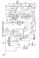
- FIG. 1a is to see a plant with a single distillation column system.
- it has a "mean oxygen capacity" of, for example, 100,000 to 140,000 Nm 3 / h.
- the distillation column system of the embodiment of the FIG. 1a comprises a high-pressure column 101, a low-pressure column 102, a main condenser 103, an argon discharge column 152 and an auxiliary column 140.
- the main capacitor 103 is formed in the example by a six-stage cascade evaporator, so a multi-level pocket evaporator.
- the pair of columns 101/102 is not arranged in the form of a double column, but next to each other.
- the argon discharge column 152 and the auxiliary column are housed according to the invention in a common container 160 with a vertical partition wall 161.
- the partition wall 161 is flat in the example and extends from the lid to the bottom of the container, so that the two subspaces forming the argon discharge column 152 and the auxiliary column 140 are completely separated; For example, different levels can also form in the sump, as shown in the drawing.
- An argon discharge head condenser 155 is located immediately above the common container 160; he is here designed as a single-storey bath evaporator.
- a shown system comprises an inlet filter 302 for atmospheric air (AIR), a main air compressor 303, an air pre-cooling unit 304, an air cleaning unit 305 (usually formed by a pair of molecular sieve adsorbers), an air compressor 306 (Booster Air Compressor - BAC) with intermediate and aftercoolers and a main heat exchanger 308 on.
- AIR atmospheric air
- main air compressor 303 for atmospheric air
- air pre-cooling unit 304 usually formed by a pair of molecular sieve adsorbers
- an air compressor 306 Booster Air Compressor - BAC
- a total compressed air flow 100 from the cold end of the main heat exchanger 308 is introduced into the high pressure column 101.
- the air recompressed in the final compressor 306 to its final pressure is liquefied in the main heat exchanger 308 (or, if its pressure is supercritical, pseudo-liquefied) and fed via lines 311/111 to the distillation column system.
- a nitrogen gas stream 104, 114 from the high-pressure column 101 is introduced into the liquefaction space of the main condenser 103. There, liquid nitrogen 115 is generated therefrom, which is passed to the high-pressure column 101 at least to a first part as a first liquid nitrogen stream 105.
- a liquid oxygen stream 106 from the bottom of the low-pressure column 102 is conveyed to at least part 106 by means of a pump 106a into the evaporation space of the main condenser 103.
- Gaseous oxygen 106c formed in the evaporation space of the main condenser 103 is introduced into the first low-pressure column 102 where it forms the rising vapor.
- a second part can be obtained directly as a gaseous oxygen product and heated in the main heat exchanger 308 (not realized in this embodiment).
- a portion 106d of the liquid oxygen from the pump 106a may be cooled in a subcooling countercurrent 123 and subsequently recovered as a liquid product (LOX).
- the reflux liquid 109a for the low pressure column 102 is formed by a nitrogen-enriched liquid 120 which is withdrawn at the high pressure column 101 from an intermediate point (or alternatively directly from the top) and cooled in the subcooling countercurrent 123. From the top of the low-pressure column 102, impure nitrogen 110a is withdrawn and passed as residual gas through the supercooling countercurrent 123 and via the line 32 to the main heat exchanger 308. Another part 109b of the nitrogen-enriched liquid 120 from the high-pressure column 101 is fed to the top of the auxiliary column 140. From the top of the auxiliary column 140 also impure nitrogen 110b is withdrawn and mixed with the impure nitrogen 110a from the low pressure column. The bottom liquid 159 of the auxiliary column 140 is guided to the intermediate point of the low-pressure column 102, at which the bottoms liquid 154a of the high-pressure column 101 is also fed.
- an oxygen-enriched bottoms liquid stream 151 is withdrawn and cooled in the subcooling countercurrent 123.
- a first part 154a of the cooled bottom liquid 153 is supplied to the low-pressure column 102.
- the remainder 154b of the cooled bottom liquid 153 is introduced into the evaporation space of the argon discharge head top condenser 155.
- the vaporized in the top condenser 155 portion 156 and the remaining liquid portion 157 are the low-pressure column 102 fed.
- the argon-enriched "product" 163 of the argon column is withdrawn in gaseous form from the argon column 152 or its overhead condenser 155 and passed through the main heat exchanger 308 through a separate passage group via line 164.
- the bottom liquid 158b of the argon discharge column 152 is led to the intermediate point of the low-pressure column 102, on which the gaseous insert 158a for the argon discharge column 152 is withdrawn.
- the argon-enriched fraction 163 could be mixed with the impure nitrogen 110 and the mixture passed through the main heat exchanger.
- the liquid air 311 from the main heat exchanger is fed via the line 111 to the high-pressure column 101 at an intermediate point. At least one part 127 is removed again immediately and introduced through the subcooler 123 and via the line 128 into the low-pressure column 102, above the feed of the sump fraction 153. Via line 129 is further gaseous air from a Einblaseturbine 137 in the auxiliary column 140 (line 129a) and / or introduced into the low-pressure column 102 (line 129b). The feed into the low-pressure column takes place at the same point as the feed of the crude oxygen 154a. In a first variant of the embodiment, the entire air 129 is introduced from the injection turbine 137 in the auxiliary column 140. Deviating from this, in a second variant, the air 129 is divided between the two lines 129a and 129b.
- liquid oxygen 141 is withdrawn from the bottom of the low pressure column 102 and fed via line 14 at least partially to an internal compression.
- the liquid oxygen 14 is brought by means of a pump 15 to a high product pressure, evaporated under this high product pressure in the main heat exchanger 308 or (if its pressure is supercritical) pseudo-evaporated, warmed to about ambient temperature and finally stripped off as gaseous pressure oxygen product GOXIC.
- pressurized nitrogen is withdrawn directly from the top of the high-pressure column 101 (lines 104, 142), passed via line 42 to the main heat exchanger 308, warmed there and finally recovered as gaseous pressure nitrogen product MPGAN. Part of it can be used as sealing gas (seal gas).
- a portion 143 of the liquid nitrogen produced in the main condenser 103 may be supplied via line 43 to an internal compression (pump 16) and recovered as gaseous high pressure nitrogen product GANIC.
- the plant can also supply liquid products LOX, LIN.
- the system of FIG. 1a is designed as a two-turbine method with a medium-pressure turbine 138 and an injection turbine 137.
- FIG. 1b is different from this FIG. 1a that in FIG. 1b only one injection turbine 137, but no intermediate-pressure turbine is provided.
- FIG. 1 a rejects the system of Figure 1c in the auxiliary column two mass transfer sections 140a and 140b. Between these two sections, a portion 128b of the liquid air 128 is introduced into the auxiliary column.
- the use of an additional (third) packing section (in Figure 1c not shown) in the auxiliary column below 140b and 129a is possible in principle; then a portion of the gas stream 156 is introduced from the argon overhead condenser at the bottom of the auxiliary column.
- FIG. 2 is a plant with two distillation column systems (twin columns) shown, which is formed according to the invention. It has a "large oxygen capacity" with an oxygen production of, for example, 140,000 to 170,000 Nm 3 / h.
- the first distillation column system of the embodiment of the FIG. 2 has a first high-pressure column 101, a first low-pressure column 102, a first main capacitor 103, a first auxiliary column 140 and a first Argonausschleusklale 152 on.
- a second high-pressure column 201, a second low-pressure column 202, a second main condenser 203, a second auxiliary column 240 and a second argon column 252 belong to the second distillation column system of FIG FIG. 2 illustrated plant.
- the argon discharge column 152/262 and the auxiliary column 140/240 are each arranged in a common container 160/260 with partition wall 161/261. Both distillation column systems are constructed identically.
- Both main capacitors 103, 203 are formed in the example by a three-stage cascade evaporator.
- the pairs of columns 101/102, 201/202 are arranged in the form of two double columns.
- the common container 160/260 are each arranged above the double columns, so that one can speak of triple columns.
- the argon column head condensers 155, 255 sit directly above the common containers 140/240 and are designed as a bath evaporator.
- a total compressed air flow 99 from the cold end of the main heat exchanger 308 is branched into a first compressed air partial flow 100 and a second compressed air partial flow 200.
- the first compressed air sub-stream 100 is introduced into the first high-pressure column 101, the second compressed air sub-stream 200 into the second high-pressure column 201.
- the air recompressed in the final compressor 306 to its final pressure is liquefied in the main heat exchanger 308 (or, if its pressure is supercritical, pseudo-liquefied) and fed via line 311 to the distillation column systems where it branches into the streams 111 and 211.
- the argon-enriched "product" 163, 263 of the argon column is removed in gaseous form from the argon discharge column 152, 252 or its top condenser 155, 255 and passed via line 164 through a separate passage group through the main heat exchanger 308.
- the argon-enriched fractions 163, 263 could be mixed with the impure nitrogen 110a, 110b, 210a, 201b, 32 and the mixture passed through the main heat exchanger.
- liquid oxygen 141, 241 is withdrawn from the evaporation spaces of the main condensers 103, 203, combined and fed via line 14 at least partially to an internal compression.
- the liquid oxygen 14 is pumped by a pump 15 to a high product pressure, vaporized under this high product pressure in the main heat exchanger 308 or (if its pressure is supercritical) pseudo-evaporated, warmed to about ambient temperature and finally withdrawn as gaseous pressure oxygen product GOXIC.
- pressurized nitrogen is withdrawn directly from the head of the high-pressure columns 101, 201 (lines 142 and 242), together via line 42 to the main heat exchanger 308, where it is warmed up and finally recovered as gaseous compressed nitrogen product MPGAN.
- Part of it can be used as sealing gas (seal gas).
- sealing gas sealing gas
- a part 143, 243 of the liquid nitrogen produced in the main condensers 103, 203 can be supplied via line 43 to an internal compression (pump 16) and can be obtained as gaseous high-pressure nitrogen product GANIC.
- the plant can also supply liquid products LOX, LIN. These can be removed separately from each distillation column system as shown.
- the mass transfer elements in the two low-pressure columns 102, 202 are formed exclusively by ordered packing.
- the oxygen sections of the two low-pressure columns 102, 202 are provided with an ordered packing having a specific surface area of 750 m 2 / m 3 or alternatively 1200 m 2 / m 3 , in the remaining sections the packing has a specific surface area of 750 or 500 m 2 / m 3 on.
- the two low pressure columns 102, 202 may have a nitrogen section above the mass transfer areas shown in the drawing; this can then also be equipped with a particularly dense packing (for example with a specific surface area of 1200 m 2 / m 3 for the purpose of reducing the height of the column).
- the argon columns 152, 252 contain in the exemplary embodiment exclusively pack with a specific Surface of 1200 m 2 / m 3 or alternatively 750 m 2 / m 3 , as well as the auxiliary columns 140 and 240.
- the mass transfer elements are preferably formed by ordered packing with a specific surface area of 1200 m 2 / m 3 or 750 m 2 / m 3 .
- the mass transfer elements could be formed in one or both high pressure columns 101, 201 by conventional distillation trays, for example through sieve trays.
- FIG. 2 is analogous to FIG. 1a is formed as a two-turbine method with a medium-pressure turbine 138 and an injection turbine 137.
- a medium-pressure turbine 138 and an injection turbine 137.
- only one injection turbine can be used (see FIG. 1c) ,
- Each of the two distillation column systems is independently regulated.
- the pressure in the low-pressure columns for example, can be set and controlled separately. Through this decoupling, the overall control effort is made easier and any manufacturing tolerances in both double columns can be better compensated.
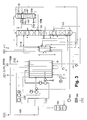
- the plant of FIG. 3 shows how FIG. 1 a only a single distillation column system on.
- the high-pressure column 101, the main condenser 103 and the low-pressure column 102 are arranged one above the other in the form of a classic double column.
- the common container 160 with partition 161, auxiliary column 140 and argon discharge column 152 is disposed adjacent to the low-pressure column 102 at a height that allows the bottom liquids 159, 158b of these columns to be introduced into the low-pressure column 102 without pumps.
- the common container can either be arranged on a scaffold or laterally connected to the low-pressure column 102 or its cold box. An oxygen transfer pump can be omitted since the columns are arranged one above the other.
Landscapes
- Engineering & Computer Science (AREA)
- Physics & Mathematics (AREA)
- Mechanical Engineering (AREA)
- Thermal Sciences (AREA)
- General Engineering & Computer Science (AREA)
- Health & Medical Sciences (AREA)
- Emergency Medicine (AREA)
- Separation By Low-Temperature Treatments (AREA)
Abstract
Das Destillationssäulen-System und das Verfahren dienen zur Erzeugung von Sauerstoff durch Tieftemperaturzerlegung von Luft in einem Destillationssäulen-System das eine Hochdrucksäule (101) und eine Niederdrucksäule (102), einen Hauptkondensator (103), der als Kondensator-Verdampfer ausgebildet ist, und eine Hilfssäule (140) aufweist. Eine gasförmige sauerstoffhaltige Fraktion (129a) wird in die Hilfssäule (140) eingeleitet. Ein stickstoffhaltiger Flüssigstrom (120, 109b) aus der Hochdrucksäule (101), dem Hauptkondensator (103) oder der Niederdrucksäule (102) wird als Rücklauf auf den Kopf der Hilfssäule (140) aufgegeben. Ein argonreicher Strom (158a) von einer einer Zwischenstelle der Niederdrucksäule (102) wird in eine Argonausschleussäule (152) eingeleitet, die einen Argonausschleussäulen-Kopfkondensator (155) aufweist. Die Argonausschleussäule (152) und die Hilfssäule (140) sind in einem gemeinsamen Behälter (160) angeordnet, der als Trennwandkolonne ausgebildet ist und eine vertikale Trennwand (161) aufweist.
Description
- Die Erfindung betrifft ein Destillationssäulen-System zur Erzeugung von Sauerstoff durch Tieftemperaturzerlegung von Luft gemäß dem Oberbegriff des Patentanspruchs 1.
- Die Grundlagen der Tieftemperaturzerlegung von Luft im Allgemeinen sowie der Aufbau von Zwei-Säulen-Anlagen im Speziellen sind in der Monografie "Tieftemperaturtechnik" von Hausen/Linde (2. Auflage, 1985) und in einem Aufsatz von Latimer in Chemical Engineering Progress (Vol. 63, No.2, 1967, Seite 35) beschrieben. Die Wärmeaustauschbeziehung zwischen Hochdrucksäule und Niederdrucksäule einer Doppelsäule wird im Regelfall durch einen Hauptkondensator realisiert, in dem Kopfgas der Hochdrucksäule gegen verdampfende Sumpfflüssigkeit der Niederdrucksäule verflüssigt wird.
- Das Destillationssäulen-System der Erfindung kann grundsätzlich als klassisches Zwei-Säulen-System mit Hochdrucksäule und Niederdrucksäule ausgebildet sein. Es kann zusätzlich zu den beiden Trennsäulen zur Stickstoff-Sauerstoff-Trennung weitere Vorrichtungen zur Gewinnung anderer Luftkomponenten, insbesondere von Edelgasen aufweisen, beispielsweise eine Krypton-Xenon-Gewinnung.
- Der Hauptkondensator ist bei der Erfindung als Kondensator-Verdampfer ausgebildet. Als "Kondensator-Verdampfer" wird ein Wärmetauscher bezeichnet, in dem ein erster, kondensierender Fluidstrom in indirekten Wärmeaustausch mit einem zweiten, verdampfenden Fluidstrom tritt. Jeder Kondensator-Verdampfer weist einen Verflüssigungsraum und einen Verdampfungsraum auf, die aus Verflüssigungspassagen beziehungsweise Verdampfungspassagen bestehen. In dem Verflüssigungsraum wird die Kondensation (Verflüssigung) des ersten Fluidstroms durchgeführt, in dem Verdampfungsraum die Verdampfung des zweiten Fluidstroms. Verdampfungs- und Verflüssigungsraum werden durch Gruppen von Passagen gebildet, die untereinander in Wärmeaustauschbeziehung stehen.
- Dabei kann der Hauptkondensator als ein- oder mehrstöckiger Badverdampfer, insbesondere als Kaskadenverdampfer (beispielsweise wie in
EP 1287302 B1 =US 6748763 B2 beschrieben), oder aber als Fallfilmverdampfer ausgebildet sein. Er kann durch einen einzigen Wärmetauscherblock gebildet werden oder auch durch mehrere Wärmetauscherblöcke, die in einem gemeinsamen Druckbehälter angeordnet sind. - Ein "Hauptwärmetauscher" dient zur Abkühlung von Einsatzluft in indirektem Wärmeaustausch mit Rückströmen aus dem Destillationssäulen-System. Er kann aus einem einzelnen oder mehreren parallel und/oder seriell verbundenen Wärmetauscherabschnitten gebildet sein, zum Beispiel aus einem oder mehreren Plattenwärmetauscher-Blöcken. Separate Wärmetauscher, die speziell der Verdampfung oder Pseudo-Verdampfung eines einzigen flüssigen oder überkritischen Fluids dienen, ohne Anwärmung und/oder Verdampfung eines weiteren Fluids, gehören nicht zum Hauptwärmetauscher.
- Die relativen räumlichen Begriffe "oben", "unten", "über", "unter", "oberhalb", "unterhalb", "nebeneinander", "vertikal", "horizontal" etc. beziehen sich hier auf die räumliche Ausrichtung der Trennsäulen im Normalbetrieb. Unter einer Anordnung zweier Säulen oder Apparateteile "übereinander" wird hier verstanden, dass sich das obere Ende des unteren der beiden Apparateteile sich auf niedrigerer oder gleicher geodätischer Höhe befindet wie das untere Ende der oberen der beiden Apparateteile und sich die Projektionen der beiden Apparateteile in eine horizontale Ebene überschneiden. Insbesondere sind die beiden Apparateteile genau übereinander angeordnet, das heißt die Achsen der beiden Säulen verlaufen auf derselben vertikalen Geraden.
- Eine Anlage der eingangs genannten Art und ein entsprechendes Verfahren sind aus
DE 1136355 B bekannt. - Der Erfindung liegt die Aufgabe zugrunde, eine derartige Anlage sehr energieeffizient und mit einer besonders hohen Kapazität für die Sauerstoffproduktion auszustatten gleichzeitig aber so kompakt auszubilden, dass sie so weit wie möglich vorgefertigt und anschließend zur Baustelle transportiert werden kann. Für solche Transporte gibt es strenge Limitierungen hinsichtlich der Höhe (Transportlänge) und des Durchmessers (Transportbreite) der Trennsäulen. Zum Beispiel werden häufig Säulendurchmesser von maximal 4,8 m vorgegeben.
- Diese Aufgabe wird durch die Merkmale des Patentanspruchs 1 gelöst. Insbesondere werden eine Argonausschleussäule und eine Hilfssäule eingesetzt und die Säulen werden in besonders vorteilhafter Weise kombiniert.
- Unter einer "Argonausschleussäule " wird hier eine Trennsäule zur Argon-Sauerstoff-Trennung bezeichnet, die nicht zur Gewinnung eines reinen Argonprodukts, sondern zur Ausschleusung von Argon der in Hochdrucksäule und Niederdrucksäule zu zerlegenden Luft dient. Ihre Schaltung unterscheidet sich nur wenig von der einer klassischen Rohargonsäule, allerdings enthält sie deutlich weniger theoretische Böden, nämlich weniger als 40, insbesondere zwischen 15 und 30. Wie bei einer Rohargonsäule ist der Sumpfbereich einer Argonausschleussäule mit einer Zwischenstelle der Niederdrucksäule verbunden und die Argonausschleussäule wird durch einen Kopfkondensator gekühlt, auf dessen Verdampfungsseite entspannte Sumpfflüssigkeit aus der Hochdrucksäule eingeleitet wird; eine Argonausschleussäule weist keinen Sumpfverdampfer auf.
- In der Hilfssäule wird ein Teil der Einsatzluft behandelt, insbesondere mindestens ein Teil eines turbinenentspannten Luftstroms, der weder in die Hochdrucksäule noch in die Niederdrucksäule geleitet wird.
- Zunächst erscheint es angesichts des Bestrebens, eine besonders kompakte Anlage zu realisieren, widersinnig zwei zusätzliche Säulen zu den üblichen, nämlich Hochdrucksäule und Niederdrucksäule einzusetzen. Im Rahmen der Erfindung hat sich jedoch überraschenderweise herausgestellt, dass sich insgesamt sowohl eine besonders hohe Kapazität als auch eine gute Baubarkeit ergibt. Die erfindungsgemäße Kombination von Hilfssäule, Argonausschleussäule und Säulenanordnung führt zu einer besonders vorteilhaften Anlage.
- Bei der Erfindung ist die Hilfssäule sozusagen in die Argonausschleussäule eingebaut, dadurch kann im Rahmen der Erfindung die Bauhöhe einer Kolonne eingespart werden oder umgekehrt der Durchsatz in der Säule bei bestehender Höhe erhöht werden, ohne dass der Säulendurchmesser die transporttechnisch zulässigen Maße überschreitet. Die Kombination aus Argonausschleussäule und Hilfssäule wird hier als "gemeinsamer Behälter" bezeichnet. Dieser weist in seinem Inneren eine vertikale Trennwand auf. Diese kann grundsätzlich jede Form aufweisen, beispielsweise Zylinderform; vorzugsweise wird jedoch eine ebene Trennwand eingesetzt. Die beiden Teilräume, welche durch die Trennwand gebildet werden, können gleich oder verschieden groß sein.
- Auf der einen Seite der Trennwand befindet sind die Argonausschleussäule, insbesondere deren Stoffaustauschelemente, auf der anderen die Hilfssäule, insbesondere deren Stoffaustauschelemente. Die Stoffaustauschvorgänge beiderseits der Trennwand sind unabhängig voneinander.
- Oben auf dem gemeinsamen Behälter kann wie bei Argonsäulen üblich der Argonausschleussäulen-Kopfkondensator angeordnet werden. Sein Verflüssigungsraum kommuniziert hier strömungstechnisch nur mit dem Kopf der Argonausschleussäule, nicht aber mit dem Kopf der Hilfssäule.
- Am Kopf der Hilfssäule wird vorzugsweise ein erstes gasförmiges Stickstoffprodukt gewonnen, am Kopf der Niederdrucksäule ein zweites gasförmiges Stickstoffprodukt. Diese beiden Stickstoffprodukte können zum Beispiel zusammengeführt und gemeinsam in einem Unterkühlungs-Gegenströmer und einem Hauptwärmetauscher auf etwa Umgebungstemperatur angewärmt werden.
- In vielen Fällen ist es günstiger, die erste und die zweite Kopffraktion separat - also in getrennten Passagengruppen - durch den Hauptwärmetauscher zu leiten und diese Fraktionen dabei gegen Einsatzluft für die Hochdrucksäule anzuwärmen. Dann kann zum Beispiel der Kopf der Niederdrucksäule unter besonders niedrigem Druck von beispielsweise 1,0 bis 1,6 bar betrieben werden, wobei am Kopf der Hilfssäule ein um etwa 0,1 bis 0,3 bar höherer Druck von 1,1 bis 1,7 bar herrscht, der ausreicht, um das Kopfgas der ersten gasförmigen Kopffraktion aus der Hilfssäule als Regeneriergas für eine Molekularsiebstation zur Luftreinigung zu nutzen. Durch den besonders niedrigen Niederdrucksäulendruck wird der Energieverbrauch der Anlage verringert.
- Allgemein ist das erfindungsgemäße Verfahren besonders gut geeignet für Anlagen besonders großer Sauerstoffkapazität von beispielsweise 80.000 bis 170.000 Nm3/h. Diese und auch weitere Kapazitätsangaben im Text beziehen sich auf einen maximalen Säulendurchmesser von 4,8 m.
- Es ist ferner günstig, wenn die Mittel zum Einleiten einer gasförmigen Fraktion, deren Sauerstoffgehalt gleich demjenigen der Luft oder höher ist, in die Hilfssäule als Mittel zum Einleiten turbinenentspannter Luft in die Hilfssäule ausgebildet sind. Hierdurch muss die Turbinenluft nur teilweise in die Niederdrucksäule eingeleitet werden.
- Grundsätzlich könnten die beiden Teilräume des gemeinsamen Behälters an ihrem unteren Ende kommunizieren, wie es bei Trennwandkolonnen allgemein üblich ist. Bei der Erfindung sind die beiden Teilräume jedoch vorzugsweise vollständig voneinander getrennt, indem der gemeinsame Behälter und die Trennwand so ausgebildet sind, dass die Trennwand die beiden Teilräume des gemeinsamen Behälters vollständig gegeneinander abdichtet. Damit sind auch die Sümpfe von Argonausschleussäule und Hilfssäule vollständig unabhänig voneinander, sowohl in der chemischen Zusammensetzung als auch in der Füllstandshöhe.
- Im Rahmen der Erfindung sind drei räumliche Anordnungen der Säulen besonders bevorzugt.
- In einer ersten Anordnung sind
- die Niederdrucksäule neben der Hochdrucksäule und
- der gemeinsame Behälter, insbesondere mit Argonausschleussäulen-Kopfkondensator, über der Hochdrucksäule angeordnet.
- Ein zweite Anordnung sieht vor,
- den Hauptkondensator über der Hochdrucksäule,
- die Niederdrucksäule über dem Hauptkondensator und
- den gemeinsamen Behälter, insbesondere mit Argonausschleussäulen-Kopfkondensator, über der Niederdrucksäule anzuordnen.
- Hochdrucksäule, Hauptkondensator und Niederdrucksäule bilden hier eine klassische Doppelsäule. Darüber befinden sich Argonausschleussäule und Hilfssäule. Ein solche Konfiguration weist einen besonders niedrigen Flächenverbrauch (Footprint) auf. Diese Ausführungsform der Erfindung weist beispielsweise eine Kapazität von 70.000 bis 85.000 Nm3/h Sauerstoff auf.
- Bei einer dritten Anordnung werden
- der Hauptkondensator über der Hochdrucksäule,
- die Niederdrucksäule über dem Hauptkondensator und
- der gemeinsame Behälter, insbesondere mit Argonausschleussäulen-Kopfkondensator, neben der Niederdrucksäule angeordnet sind.
- Besonders geeignet für eine große Sauerstoffkapazität ist eine Anlage mit mit zwei gleichen erfindungsgemäßen Destillationssäulen-Systemn, die gemäß Patentanspruch 6 parallel betrieben und aus der gleichen Quelle mit Einsatzluft versorgt werden. Eine solche Anlage mit Zwillingssäulen ist für sich in
EP 2865978 A1 beschrieben. Eine "große Sauerstoffkapazität" bezeichnet eine Anlage mit einer Sauerstoffproduktion von mehr als 140.000 Nm3/h, beispielsweise bis 170.000 Nm3/h und mehr. - Die Erfindung betrifft außerdem ein Verfahren zur Erzeugung von Sauerstoff durch Tieftemperaturzerlegung von Luft gemäß den Patentansprüchen 8 bis 14.
- Die Erfindung sowie weitere Einzelheiten der Erfindung werden im Folgenden anhand von in den Zeichnungen schematisch dargestellten Ausführungsbeispielen näher erläutert. Hierbei zeigen:
- Figuren 1a bis 1c
- ein erstes Ausführungsbeispiel der Erfindung mit Anordnung von Argonausschleussäule und Hilfssäule über der Hochdrucksäule beziehungsweise über dem Hauptkondensator in drei Varianten,
- Figur 2
- ein zweites Ausführungsbeispiel mit Zwillingssäulen, bei dem in jedem Teilsystem alle Säulen übereinander angeordnet sind, und
- Figur 3
- ein drittes Ausführungsbeispiel, bei dem der gemeinsame Behälter neben einer klassischen Doppelsäule angeordnet ist.
- In
Figur 1a ist eine Anlage mit einem einzigen Destillationssäulen-System zu sehen. Sie weist insbesondere eine "mittlere Sauerstoffkapazität" von beispielsweise 100.000 bis 140.000 Nm3/h auf. Das Destillationssäulen-System des Ausführungsbeispiels derFigur 1a weist eine Hochdrucksäule 101, eine Niederdrucksäule 102, einen Hauptkondensator 103, eine Argonausschleussäule 152 und eine Hilfssäule 140 auf. - Der Hauptkondensator 103 wird in dem Beispiel durch einen sechsstufigen Kaskadenverdampfer gebildet, also einen mehrstöckigen Taschenverdampfer. Das Säulenpaar 101/102 ist nicht in Form einer Doppelsäule angeordnet, sondern nebeneinander.
- Die Argonausschleussäule 152 und die Hilfssäule sind erfindungsgemäß in einem gemeinsamen Behälter 160 mit vertikaler Trennwand 161 untergebracht. Die Trennwand 161 ist in dem Beispiel eben und reicht vom Deckel bis zum Boden des Behälters, sodass die beiden Teilräume, welche die Argonausschleussäule 152 und die Hilfssäule 140 bilden, vollständig getrennt sind; zum Beispiel können sich auch im Sumpf unterschiedliche Füllstände ausbilden, wie in der Zeichnung dargestellt ist. Ein Argonausschleussäulen-Kopfkondensator 155 sitzt unmittelbar über dem gemeinsamen Behälter 160; er ist hier als einstöckiger Badverdampfer ausgebildet.
- Die in
Figur 1 a dargestellte Anlage weist ein Eintrittsfilter 302 für atmosphärische Luft (AIR), einen Hauptluftverdichter 303, eine Luftvorkühlungseinheit 304, eine Luftreinigungseinheit 305 (üblicherweise gebildet durch ein Paar von Molekularsieb-Adsorbern), einen Luftnachverdichter 306 (Booster Air Compressor - BAC) mit Zwischen- und Nachkühlern und einen Hauptwärmetauscher 308 auf. Ein Gesamtdruckluftstrom 100 vom kalten Ende des Hauptwärmetauschers 308 wird in die Hochdrucksäule 101 eingeleitet. - Die in dem Nachverdichter 306 auf dessen Enddruck nachverdichtete Luft wird in dem Hauptwärmetauscher 308 verflüssigt (oder - falls ihr Druck überkritisch ist - pseudoverflüssigt) und über Leitungen 311/111 dem Destillationssäulen-System zugeleitet.
- Ein Stickstoffgasstrom 104, 114 aus der Hochdrucksäule 101 wird in den Verflüssigungsraum des Hauptkondensators 103 eingeleitet. Dort wird daraus Flüssigstickstoff 115 erzeugt, der mindestens zu einem ersten Teil als ein erster Flüssigstickstoffstrom 105 zur Hochdrucksäule 101 geleitet wird.
- Ein Flüssigsauerstoffstrom 106 aus dem Sumpf der Niederdrucksäule 102 wird mindestens zu einem Teil 106 mittels einer Pumpe 106a in den Verdampfungsraum des Hauptkondensators 103 gefördert. In dem Verdampfungsraum des Hauptkondensators 103 gebildeter gasförmiger Sauerstoff 106c wird in die erste Niederdrucksäule 102 eingeleitet und bildet dort den aufsteigenden Dampf. Ein zweiter Teil kann bei Bedarf direkt als gasförmiges Sauerstoffprodukt gewonnen und im Hauptwärmetauscher 308 angewärmt werden (in diesem Ausführungsbeispiel nicht realisiert). Ein Teil 106d des Flüssigsauerstoffs aus der Pumpe 106a kann in einem Unterkühlungs-Gegenströmer 123 abgekühlt und anschließend als Flüssigprodukt (LOX) gewonnen werden.
- Die Rücklaufflüssigkeit 109a für die Niederdrucksäule 102 wird durch eine stickstoffangereicherte Flüssigkeit 120 gebildet, die an der Hochdrucksäule 101 von einer Zwischenstelle (oder alternativ direkt vom Kopf) abgezogen und in dem Unterkühlungs-Gegenströmer 123 abgekühlt wird. Vom Kopf der Niederdrucksäule 102 wird unreiner Stickstoff 110a abgezogen und als Restgas durch den Unterkühlungs-Gegenströmer 123 und über die Leitung 32 zum Hauptwärmetauscher 308 geführt. Ein anderer Teil 109b der stickstoffangereicherten Flüssigkeit 120 aus der Hochdrucksäule 101 wird auf den Kopf der Hilfssäule 140 aufgegeben. Vom Kopf der Hilfssäule 140 wird ebenfalls unreiner Stickstoff 110b abgezogen und mit dem unreinen Stickstoff 110a aus der Niederdrucksäule vermischt. Die Sumpfflüssigkeit 159 der Hilfssäule 140 wird zu der Zwischenstelle der Niederdrucksäule 102 geführt, an der auch die Sumpfflüssigkeit 154a der Hochdrucksäule 101 eingespeist wird.
- Von der Hochdrucksäule 101 wird ein sauerstoffangereicherter Sumpfflüssigkeitsstrom 151 abgezogen und im Unterkühlungs-Gegenströmer 123 abgekühlt. Ein erster Teil 154a der abgekühlten Sumpfflüssigkeit 153 wird der Niederdrucksäule 102 zugeführt. Der Rest 154b der abgekühlten Sumpfflüssigkeit 153 wird in den Verdampfungsraum des Argonausschleussäulen-Kopfkondensators 155 eingeleitet. Der im Kopfkondensator 155 verdampfte Anteil 156 und der flüssig verbliebene Anteil 157 werden der Niederdrucksäule 102 zugespeist. Das argonangereicherte "Produkt" 163 der Argonsäule wird gasförmig aus der Argonsäule 152 beziehungsweise deren Kopfkondensator 155 entnommen und über Leitung 164 durch eine separate Passagengruppe durch den Hauptwärmetauscher 308 geführt.Die Sumpfflüssigkeit 158b der Argonausschleussäule 152 wird zu Zwischenstelle der Niederdrucksäule 102 geführt, an der auch der gasförmige Einsatz 158a für die Argonausschleussäule 152 abgezogen wird.
- Alternativ könnte die argonangereicherte Fraktion 163 mit dem unreinen Stickstoff 110 vermischt und das Gemisch durch den Hauptwärmetauscher geführt werden.
- Die flüssige Luft 311 aus dem Hauptwärmetauscher wird über die Leitung 111 der Hochdrucksäule 101 an einer Zwischenstelle zugespeist. Mindestens ein Teil 127 wird gleich wieder entnommen und durch den Unterkühler 123 und über die Leitung 128 in die Niederdrucksäule 102 eingeleitet, und zwar oberhalb der Einspeisung der Sumpffraktion 153. Über Leitung 129 wird ferner gasförmige Luft aus einer Einblaseturbine 137 in die Hilfssäule 140 (Leitung 129a) und/oder in die Niederdrucksäule 102 (Leitung 129b) eingeführt. Die Einspeisung in die Niederdrucksäule findet an der gleichen Stelle wie die Einspeisung des Rohsauerstoffs 154a statt. In einer ersten Variante des Ausführungsbeispiels wird die gesamte Luft 129 aus der Einblaseturbine 137 in die Hilfssäule 140 eingeleitet. Abweichend davon wird in einer zweiten Variante die Luft 129 auf die beiden Leitungen 129a und 129b aufgeteilt.
- Als Hauptprodukt des Destillationssäulen-Systems wird flüssiger Sauerstoff 141 vom Sumpf der Niederdrucksäule 102 abgezogen und über Leitung 14 mindestens teilweise einer Innenverdichtung zugeführt. Dabei wird der flüssige Sauerstoff 14 mittels einer Pumpe 15 auf einen hohen Produktdruck gebracht, unter diesem hohen Produktdruck in dem Hauptwärmetauscher 308 verdampft oder (falls sein Druck überkritisch ist) pseudo-verdampft, auf etwa Umgebungstemperatur angewärmt und schließlich als gasförmiges Drucksauerstoffprodukt GOXIC abgezogen. Dieses stellt das Hauptprodukt der Anlage des Ausführungsbeispiels dar.
- Als weiteres Produkt der Anlage wird Druckstickstoff direkt vom Kopf der Hochdrucksäule 101 abgezogen (Leitungen 104, 142), über Leitung 42 zum Hauptwärmetauscher 308 geführt, dort angewärmt und schließlich als gasförmiges Druckstickstoffprodukt MPGAN gewonnen. Ein Teil davon kann als Dichtgas (Sealgas) eingesetzt werden. Zusätzlich kann ein Teil 143 des in dem Hauptkondensator 103 erzeugten Flüssigstickstoffs über Leitung 43 einer Innenverdichtung zugeführt (Pumpe 16) und als gasförmiges Hochdruck-Stickstoffprodukt GANIC gewonnen werden. Die Anlage kann auch Flüssigprodukte LOX, LIN liefern.
- Das System von
Figur 1a ist als Zwei-Turbinen-Verfahren mit einer Mitteldruckturbine 138 und einer Einblaseturbine 137 ausgebildet. -
Figur 1b unterscheidet sich dadurch vonFigur 1a , dass inFigur 1b nur eine Einblaseturbine 137, aber keine Mitteldruckturbine vorgesehen ist. - Zusätzlich zu den Merkmalen der
Figur 1 a weist das System vonFigur 1c in der Hilfssäule zwei Stoffaustauschabschnitte 140a und 140b auf. Zwischen diesen beiden Abschnitten wird ein Teil 128b der flüssigen Luft 128 in die Hilfssäule eingeleitet. Auch der Einsatz eines zusätzlichen (dritten) Packungsabschnittes (inFigur 1c nicht dargestellt) in der Hilfssäule unterhalb von 140b und 129a ist prinzipiell möglich; dann wird ein Teil des Gasstroms 156 aus dem Argon-Kopfkondensator am Sumpf der Hilfsäule eingeführt. - In
Figur 2 ist eine Anlage mit zwei Destillationssäulen-Systemen (Zwillingssäulen) dargestellt, die erfindungsgemäß ausgebildet ist. Sie weist eine "große Sauerstoffkapazität" mit einer Sauerstoffproduktion von beispielsweise 140.000 bis 170.000 Nm3/h auf. - Das erste Destillationssäulen-System des Ausführungsbeispiels der
Figur 2 weist eine erste Hochdrucksäule 101, eine erste Niederdrucksäule 102, einen ersten Hauptkondensator 103, eine erste Hilfssäule 140 und eine erste Argonausschleussäule 152 auf. Eine zweite Hochdrucksäule 201, eine zweite Niederdrucksäule 202, ein zweiter Hauptkondensator 203, eine zweite Hilfssäule 240 und eine zweite Argonsäule 252 gehören zu dem zweiten Destillationssäulen-System der inFigur 2 dargestellten Anlage. In beiden Destillationssäulen-Systemen sind die Argonausschleussäule 152/262 und die Hilfssäule 140/240 jeweils in einem gemeinsamen Behälter 160/260 mit Trennwand 161/261 angeordnet. Beide Destillationssäulen-Systeme sind identisch aufgebaut. - Beide Hauptkondensatoren 103, 203 werden in dem Beispiel durch je einen dreistufigen Kaskadenverdampfergebildet. Die Säulenpaare 101/102, 201/202 sind in Form zweier Doppelsäulen angeordnet. Die gemeinsamen Behälter 160/260 sind jeweils oberhalb der Doppelsäulen angeordnet, sodass man auch von Dreifachsäulen sprechen kann. Die Argonsäulen-Kopfkondensatoren 155, 255 sitzen direkt über den gemeinsamen Behältern 140/240 und sind als Badverdampfer ausgebildet.
- Ein Gesamtdruckluftstrom 99 vom kalten Ende des Hauptwärmetauschers 308 wird in einen ersten Druckluftteilstrom 100 und einen zweiten Druckluftteilstrom 200 verzweigt. Der erste Druckluftteilstrom 100 wird in die erste Hochdrucksäule 101, der zweite Druckluftteilstrom 200 in die zweite Hochdrucksäule 201 eingeleitet.
- Die in dem Nachverdichter 306 auf dessen Enddruck nachverdichtete Luft wird in dem Hauptwärmetauscher 308 verflüssigt (oder - falls ihr Druck überkritisch ist - pseudoverflüssigt) und über Leitung 311 den Destillationssäulen-Systemen zugeleitet und dort in die Ströme 111 und 211 verzweigt.
- Das argonangereicherte "Produkt" 163, 263 der Argonsäule wird gasförmig aus der Argonausschleussäule 152, 252 beziehungsweise deren Kopfkondensator 155, 255 entnommen und über Leitung 164 durch eine separate Passagengruppe durch den Hauptwärmetauscher 308 geführt.
- Alternativ könnten die argonangereicherten Fraktionen 163, 263 mit dem unreinen Stickstoff 110a, 110b, 210a, 201 b, 32 vermischt und das Gemisch durch den Hauptwärmetauscher geführt werden.
- Als Hauptprodukt der Destillationssäulen-Systeme wird flüssiger Sauerstoff 141, 241 von den Verdampfungsräumen der Hauptkondensatoren 103, 203 abgezogen, zusammengeführt und über Leitung 14 mindestens teilweise einer Innenverdichtung zugeführt. Dabei wird der flüssige Sauerstoff 14 mittels einer Pumpe 15 auf einen hohen Produktdruck gepumpt, unter diesem hohen Produktdruck in dem Hauptwärmetauscher 308 verdampft oder (falls sein Druck überkritisch ist) pseudo-verdampft, auf etwa Umgebungstemperatur angewärmt und schließlich als gasförmiges Drucksauerstoffprodukt GOXIC abgezogen. Dieses stellt das Hauptprodukt der Anlage des Ausführungsbeispiels dar.
- Als weiteres Produkt der Anlage wird Druckstickstoff direkt vom Kopf der Hochdrucksäulen 101, 201 abgezogen (Leitungen 142 und 242), gemeinsam über Leitung 42 zum Hauptwärmetauscher 308 geführt, dort angewärmt und schließlich als gasförmiges Druckstickstoffprodukt MPGAN gewonnen. Ein Teil davon kann als Dichtgas (Sealgas) eingesetzt werden. Zusätzlich kann jeweils ein Teil 143, 243 des in den Hauptkondensatoren 103, 203 erzeugten Flüssigstickstoffs über Leitung 43 einer Innenverdichtung zugeführt (Pumpe 16) und als gasförmiges Hochdruck-Stickstoffprodukt GANIC gewonnen werden.
- Die Anlage kann auch Flüssigprodukte LOX, LIN liefern. Diese können, wie dargestellt von jedem Destillationssäulen-System getrennt abgeführt werden.
- In einem konkreten Beispiel werden die Stoffaustauschelemente in den beiden Niederdrucksäulen 102, 202 ausschließlich durch geordnete Packung gebildet. Die Sauerstoffabschnitte der beiden Niederdrucksäulen 102, 202 sind mit einer geordneten Packung mit einer spezifischen Oberfläche von 750 m2/m3 oder alternativ 1200 m2/m3 ausgestattet, in den übrigen Abschnitten weist die Packung eine spezifische Oberfläche von 750 oder 500 m2/m3 auf. Zusätzlich können die beiden Niederdrucksäulen 102, 202 einen Stickstoffabschnitt oberhalb der in der Zeichnung dargestellten Stoffaustauschbereiche aufweisen; dieser kann dann ebenfalls mit besonders dichter Packung (zum Beispiel mit einer spezifischen Oberfläche von 1200 m2/m3 zwecks Reduktion der Säulenhöhe) ausgestattet werden. Abweichend hiervon ist es möglich, innerhalb jedes der genannten Abschnitte geordnete Packung unterschiedlicher spezifischer Oberfläche zu kombinieren. Die Argonsäulen 152, 252 enthalten in dem Ausführungsbeispiel ausschließlich Packung mit einer spezifischen Oberfläche von 1200 m2/m3 oder alternativ 750 m2/m3, ebenso die Hilfssäulen 140 und 240.
- In den Hochdrucksäulen 101, 201 werden die Stoffaustauschelemente vorzugsweise durch geordnete Packung mit einer spezifischen Oberfläche von 1200 m2/m3 oder 750 m2/m3 gebildet. Alternativ könnte mindestens ein Teil der Stoffaustauschelemente in einer oder beiden Hochdrucksäulen 101, 201 durch konventionelle Destillationsböden gebildet werden, zum Beispiel durch Siebböden.
- Das System von
Figur 2 ist analog zurFigur 1a als Zwei-Turbinen-Verfahren mit einer Mitteldruckturbine 138 und einer Einblaseturbine 137 ausgebildet. Alternativ könnte bei dem System derFigur 2 auch nur eine Einblaseturbine eingesetzt werden (vergleicheFigur 1 c) . - Jedes der beiden Destillationssäulen-Systeme wird unabhängig geregelt. Der Druck in den Niederdrucksäulen kann beispielsweise separat eingestellt und geregelt werden. Durch diese Entkopplung wird auch der Gesamt-Regelungsaufwand leichter gestaltet und eventuelle Fertigungstoleranzen bei beiden Doppelsäulen können besser ausgeglichen werden.
- Die Anlage von
Figur 3 weist wieFigur 1 a nur ein einziges Destillationssäulen-System auf. Allerdings sind hier die Hochdrucksäule 101, der Hauptkondensator 103 und die Niederdrucksäule 102 in Form einer klassischen Doppelsäule übereinander angeordnet. Der gemeinsame Behälter 160 mit Trennwand 161, Hilfssäule 140 und Argonausschleussäule 152 ist neben der Niederdrucksäule 102 angeordnet, und zwar auf einer Höhe, die es erlaubt, dass die Sumpfflüssigkeiten 159, 158b dieser Säulen ohne Pumpen in die Niederdrucksäule 102 einzuleiten. Der gemeinsame Behälter kann dabei entweder auf einem Gerüst angeordnet oder seitlich mit der Niederdrucksäule 102 beziehungsweise deren Coldbox verbunden sein. Eine Sauerstoff-Transferpumpe kann entfallen, da die Säulen übereinander angeordnet sind.
Claims (14)
- Destillationssäulen-System zur Erzeugung von Sauerstoff durch Tieftemperaturzerlegung von Luft mit- einer Hochdrucksäule (101) und einer Niederdrucksäule (102) und- einem Hauptkondensator (103), der als Kondensator-Verdampfer ausgebildet ist, wobei- der Verflüssigungsraum des Hauptkondensators (103) mit dem Kopf der Hochdrucksäule (101) in Strömungsverbindung (104, 114, 115, 105) steht und der Verdampfungsraum des Hauptkondensators (103) mit der Niederdrucksäule (102) in Strömungsverbindung (106, 106b, 106c) steht, und mit- einer Sauerstoffproduktleitung (41, 141, 241), die mit der Niederdrucksäule (102, 202) verbunden ist,- einer Hilfssäule (140),- Mitteln zum Einleiten einer gasförmigen Fraktion (129a), deren Sauerstoffgehalt gleich demjenigen der Luft oder höher ist, in die Hilfssäule (140) und- einer Rücklaufflüssigkeitsleitung (120,109b) zum Einleiten eines Flüssigstroms aus der Hochdrucksäule (101), dem Hauptkondensator (103) oder der Niederdrucksäule (102) als Rücklauf auf den Kopf der Hilfssäule (140), wobei der Flüssigstrom einen Stickstoffgehalt aufweist, der mindestens gleich demjenigen der Luft ist,gekennzeichnet durch- eine Argonausschleussäule (152), die in Strömungsverbindung (158a, 158b) mit einer Zwischenstelle der Niederdrucksäule (102) steht,- einen Argonausschleussäulen-Kopfkondensator (155), der als Kondensator-Verdampfer ausgebildet ist, wobei der Verflüssigungsraum des Argonausschleussäulen-Kopfkondensators (155) mit dem Kopf der Argonausschleussäule (152) in Strömungsverbindung steht, und- eine Rohsauerstoffleitung (151, 153, 154b) zum Einleiten von flüssigem Rohsauerstoff aus dem Sumpf der Hochdrucksäule (101) in den Verdampfungsraum des Argonausschleussäulen-Kopfkondensators (155), wobei- die Argonausschleussäule (152) und die Hilfssäule (140) in einem gemeinsamen Behälter (160) angeordnet sind, der als Trennwandkolonne ausgebildet ist und eine vertikale Trennwand (161) aufweist, die zwei Teilräume voneinander abtrennt, wobei der erste Teilraum die Argonausschleussäule (152) und der zweite Teilraum die Hilfssäule (140) bilden.
- Destillationssäulen-System nach Anspruch 1, dadurch gekennzeichnet, dass die Mittel zum Einleiten einer gasförmigen Fraktion, deren Sauerstoffgehalt gleich demjenigen der Luft oder höher ist, in die Hilfssäule als Mittel zum Einleiten turbinenentspannter Luft (129, 129a) in die Hilfssäule (140) ausgebildet sind.
- Destillationssäulen-System nach einerm der Ansprüche 1 oder 6, dadurch gekennzeichnet, dass die Trennwand (161) die beiden Teilräume des gemeinsamen Behälters (160) vollständig gegeneinander abdichtet.
- Destillationssäulen-System nach einerm der Ansprüche 1 bis 3, dadurch gekennzeichnet, dass- die Niederdrucksäule (102) neben der Hochdrucksäule (101) und- der gemeinsame Behälter (160), über der Hochdrucksäule (101), insbesondere über dem Hauptkondensator (103) angeordnet sind,- wobei insbesondere der Argonausschleussäulen-Kopfkondensator (155) unmittelbar über dem gemeinsamen Behälter (160) angeordnet ist.
- Destillationssäulen-System nach einem der Ansprüche 1 bis 3, dadurch gekennzeichnet, dass- der Hauptkondensator (103) über der Hochdrucksäule (101),- die Niederdrucksäule (102) über dem Hauptkondensator (103) und- der gemeinsame Behälter (160) über der Niederdrucksäule (102) angeordnet sind,- wobei insbesondere der Argonausschleussäulen-Kopfkondensator (155) unmittelbar über dem gemeinsamen Behälter (160) angeordnet ist.
- Tieftemperatur-Luftzerlegungsanlage mit- einem ersten Destillationssäulen-System gemäß einem der Ansprüche 1 bis 5, insbesondere gemäß Anspruch 5,- einem zweiten Destillationssäulen-System gemäß einem der Ansprüche 1 bis 5, insbesondere gemäß Anspruch 5,- einem Hauptluftverdichter-System (303) zum Verdichten von Einsatzluft auf einen Einsatzluftdruck,- einem Hauptwärmetauscher-System (308) zum Abkühlen von verdichteter Einsatzluft,- einer ersten Luftleitung (100) zum Einleiten von Einsatzluft in die HDS (101) des ersten Destillationssäulen-Systems und mit- einer zweiten Luftleitung (200) zum Einleiten von Einsatzluft in die HDS (201) des zweiten Destillationssäulen-Systems.
- Destillationssäulen-System nach einem der Ansprüche 1 bis 3, dadurch gekennzeichnet, dass- der Hauptkondensator (103) über der Hochdrucksäule (101),- die Niederdrucksäule (102) über dem Hauptkondensator (103) und- der gemeinsame Behälter (160) neben der Niederdrucksäule (102) angeordnet sind,- wobei insbesondere der Argonausschleussäulen-Kopfkondensator (155) unmittelbar über dem gemeinsamen Behälter (160) angeordnet ist.
- Verfahren zur Erzeugung von Sauerstoff durch Tieftemperaturzerlegung von Luft- in einem Destillationssäulen-System, das- eine Hochdrucksäule (101) und eine Niederdrucksäule (102),- einen Hauptkondensator (103), der als Kondensator-Verdampfer ausgebildet ist, wobei der Verflüssigungsraum des Hauptkondensators (103) mit dem Kopf der Hochdrucksäule (102) in Strömungsverbindung (104, 114, 115, 105) steht und der Verdampfungsraum des Hauptkondensators (103) mit der Niederdrucksäule (102) in Strömungsverbindung (106, 106b, 106c) steht, und- eine Hilfssäule (140)aufweist, wobei- ein Sauerstoffstrom (41, 141, 241) aus der Niederdrucksäule (102) abgezogen und als Sauerstoffprodukt gewonnen wird.- eine gasförmige Fraktion (129a), deren Sauerstoffgehalt gleich demjenigen der Luft oder höher ist, in die Hilfssäule (140) eingeleitet wird und- ein Flüssigstrom (120, 109b) aus der Hochdrucksäule (101), dem Hauptkondensator (103) oder der Niederdrucksäule (102) als Rücklauf auf den Kopf der Hilfssäule (140) aufgegeben wird, wobei der Flüssigstrom einen Stickstoffgehalt aufweist, der mindestens gleich demjenigen der Luft ist,dadurch gekennzeichnet, dass- ein argonreicher Strom (158a) von einer einer Zwischenstelle der Niederdrucksäule (102) in eine Argonausschleussäule (152) eingeleitet wird,- Rücklauf für die Argonausschleussäule (152) in einem Argonausschleussäulen-Kopfkondensator (155) erzeugt wird, der als Kondensator-Verdampfer ausgebildet ist, wobei der Verflüssigungsraum des Argonausschleussäulen-Kopfkondensators (155) mit dem Kopf der Argonausschleussäule (152) in Strömungsverbindung (38) steht,- Rohsauerstoff (151, 153, 154b) aus dem Sumpf der Hochdrucksäule (101) in den Verdampfungsraum des Argonausschleussäulen-Kopfkondensators (155) eingeleitet wird und- die Argonausschleussäule (152) und die Hilfssäule (140) in einem gemeinsamen Behälter (160) angeordnet sind, der als Trennwandkolonne ausgebildet ist und eine vertikale Trennwand (161) aufweist, die zwei Teilräume voneinander abtrennt, wobei der erste Teilraum die Argonausschleussäule (152) und der zweite Teilraum die Hilfssäule (140) bilden.
- Verfahren nach Anspruch 8, dadurch gekennzeichnet, dass die gasförmige Fraktion, deren Sauerstoffgehalt gleich demjenigen der Luft oder höher ist, durch turbinenentspannte Luft (129, 129a) gebildet wird.
- Verfahren nach einerm der Ansprüche 8 oder 9, dadurch gekennzeichnet, dass die Trennwand (161) die beiden Teilräume des gemeinsamen Behälters vollständig gegeneinander abdichtet.
- Verfahren nach einerm der Ansprüche 8 bis 10, dadurch gekennzeichnet, dass- die Niederdrucksäule (102) neben der Hochdrucksäule (101) und- der gemeinsame Behälter (160) über der Hochdrucksäule angeordnet sind,- wobei insbesondere der Argonausschleussäulen-Kopfkondensator (155) unmittelbar über dem gemeinsamen Behälter (160) angeordnet ist.
- Verfahren nach einerm der Ansprüche 8 bis 10, dadurch gekennzeichnet, dass- der Hauptkondensator (103) über der Hochdrucksäule (101),- die Niederdrucksäule (102) über dem Hauptkondensator (103) und- der gemeinsame Behälter (160) über der Niederdrucksäule (102) angeordnet sind,- wobei insbesondere der Argonausschleussäulen-Kopfkondensator (155) unmittelbar über dem gemeinsamen Behälter (160) angeordnet ist.
- Verfahren nach einem der Ansprüche 8 bis 12, das in einer Tieftemperatur-Luftzerlegungsanlage gemäß Anspruch 6 durchgeführt wird und bei dem- Einsatzluft in einem Hauptluftverdichter-System (303) auf einen Einsatzluftdruck verdichtet wird"- mindestens ein Teil der verdichteten Einsatzluft einem Hauptwärmetauscher-System (308) abgekühlt wird,- ein erster Teil der abgekühlten Einsatzluft durch eine erste Luftleitung (100) zum in die HDS (101) des ersten Destillationssäulen-Systems eingeleitet wird und- ein zweiter Teil der abgekühlten Einsatzluft durch eine zweite Luftleitung (200) in die HDS (201) des zweiten Destillationssäulen-Systems eingeleitet wird.
- Verfahren nach einerm der Ansprüche 8 bis 13, dadurch gekennzeichnet, dass- der Hauptkondensator (103) über der Hochdrucksäule (101),- die Niederdrucksäule (102) über dem Hauptkondensator (103) und- der gemeinsame Behälter (160), neben der Niederdrucksäule (102) angeordnet sind,- wobei insbesondere der Argonausschleussäulen-Kopfkondensator (155) unmittelbar über dem gemeinsamen Behälter (160) angeordnet ist.
Priority Applications (1)
| Application Number | Priority Date | Filing Date | Title |
|---|---|---|---|
| EP15003096.3A EP3163237A1 (de) | 2015-10-29 | 2015-10-29 | Destillationssäulen-system und verfahren zur erzeugung von sauerstoff durch tieftemperaturzerlegung von luft |
Applications Claiming Priority (1)
| Application Number | Priority Date | Filing Date | Title |
|---|---|---|---|
| EP15003096.3A EP3163237A1 (de) | 2015-10-29 | 2015-10-29 | Destillationssäulen-system und verfahren zur erzeugung von sauerstoff durch tieftemperaturzerlegung von luft |
Publications (1)
| Publication Number | Publication Date |
|---|---|
| EP3163237A1 true EP3163237A1 (de) | 2017-05-03 |
Family
ID=54427530
Family Applications (1)
| Application Number | Title | Priority Date | Filing Date |
|---|---|---|---|
| EP15003096.3A Withdrawn EP3163237A1 (de) | 2015-10-29 | 2015-10-29 | Destillationssäulen-system und verfahren zur erzeugung von sauerstoff durch tieftemperaturzerlegung von luft |
Country Status (1)
| Country | Link |
|---|---|
| EP (1) | EP3163237A1 (de) |
Citations (7)
| Publication number | Priority date | Publication date | Assignee | Title |
|---|---|---|---|---|
| DE1136355B (de) | 1961-01-26 | 1962-09-13 | Linde S Eismaschinen Ag Zweign | Verfahren und Einrichtung zur Tieftemperaturrektifikation von Gasgemischen |
| US5836174A (en) * | 1997-05-30 | 1998-11-17 | Praxair Technology, Inc. | Cryogenic rectification system for producing multi-purity oxygen |
| US20020178747A1 (en) * | 2001-03-21 | 2002-12-05 | Linde Aktiengesellschaft | Obtaining argon using a three-column system for the fractionation of air and a crude argon column |
| US6748763B2 (en) | 2000-05-31 | 2004-06-15 | Linde Ag | Multistoreyed bath condenser |
| EP2161063A1 (de) * | 2008-09-03 | 2010-03-10 | L'Air Liquide Société Anonyme pour l'Etude et l'Exploitation des Procédés Georges Claude | Verfahren zur Herstellung einer Kolonne mit Trennwand |
| FR2964451A3 (fr) * | 2011-12-05 | 2012-03-09 | Air Liquide | Installation de separation d'un gaz de l'air par separation cryogenique |
| EP2865978A1 (de) | 2013-10-25 | 2015-04-29 | Linde Aktiengesellschaft | Verfahren zur Tieftemperaturzerlegung von Luft und Tieftemperatur-Luftzerlegungsanlage |
-
2015
- 2015-10-29 EP EP15003096.3A patent/EP3163237A1/de not_active Withdrawn
Patent Citations (8)
| Publication number | Priority date | Publication date | Assignee | Title |
|---|---|---|---|---|
| DE1136355B (de) | 1961-01-26 | 1962-09-13 | Linde S Eismaschinen Ag Zweign | Verfahren und Einrichtung zur Tieftemperaturrektifikation von Gasgemischen |
| US5836174A (en) * | 1997-05-30 | 1998-11-17 | Praxair Technology, Inc. | Cryogenic rectification system for producing multi-purity oxygen |
| US6748763B2 (en) | 2000-05-31 | 2004-06-15 | Linde Ag | Multistoreyed bath condenser |
| EP1287302B1 (de) | 2000-05-31 | 2005-09-21 | Linde AG | Mehrstöckiger badkondensator |
| US20020178747A1 (en) * | 2001-03-21 | 2002-12-05 | Linde Aktiengesellschaft | Obtaining argon using a three-column system for the fractionation of air and a crude argon column |
| EP2161063A1 (de) * | 2008-09-03 | 2010-03-10 | L'Air Liquide Société Anonyme pour l'Etude et l'Exploitation des Procédés Georges Claude | Verfahren zur Herstellung einer Kolonne mit Trennwand |
| FR2964451A3 (fr) * | 2011-12-05 | 2012-03-09 | Air Liquide | Installation de separation d'un gaz de l'air par separation cryogenique |
| EP2865978A1 (de) | 2013-10-25 | 2015-04-29 | Linde Aktiengesellschaft | Verfahren zur Tieftemperaturzerlegung von Luft und Tieftemperatur-Luftzerlegungsanlage |
Non-Patent Citations (2)
| Title |
|---|
| HAUSEN; LINDE: "Tieftemperaturtechnik", 1985 |
| LATIMER, CHEMICAL ENGINEERING PROGRESS, vol. 63, no. 2, 1967, pages 35 |
Similar Documents
| Publication | Publication Date | Title |
|---|---|---|
| EP1243881B1 (de) | Drei-Säulen-System zur Tieftemperatur-Luftzerlegung | |
| EP3133361B1 (de) | Destillationssäulen-system und anlage zur erzeugung von sauerstoff durch tieftemperaturzerlegung von luft | |
| EP1376037B1 (de) | Luftzerlegungsverfahren und -anlage mit Mischsäule und Krypton-Xenon-Gewinnung | |
| EP1482266A1 (de) | Verfahren und Vorrichtung zur Gewinnung von Krypton und/oder Xenon durch Tieftemperaturzerlegung von Luft | |
| EP2758734B1 (de) | Verfahren und vorrichtung zur tieftemperaturzerlegung von luft | |
| EP2986924B1 (de) | Nachrüstbare vorrichtung zur tieftemperaturzerlegung von luft, nachrüstanlage und verfahren zum nachrüsten einer tieftemperatur-luftzerlegungsanlage | |
| WO2016146246A1 (de) | Anlage zur erzeugung von sauerstoff durch tieftemperaturzerlegung von luft | |
| EP2938952A2 (de) | Verfahren und vorrichtung zur tieftemperatur-luftzerlegung | |
| EP3327393A1 (de) | Verfahren und vorrichtung zur gewinnung eines hochreinsauerstoffproduktstroms durch tieftemperaturzerlegung von luft | |
| EP1319913A1 (de) | Vorrichtung und Verfahren zur Erzeugung gasförmigen Sauerstoffs unter erhöhtem Druck | |
| EP3067650B1 (de) | Anlage und verfahren zur erzeugung von sauerstoff durch tieftemperaturzerlegung von luft | |
| EP3067649A1 (de) | Destillationssäulen-system und verfahren zur erzeugung von sauerstoff durch tieftemperaturzerlegung von luft | |
| WO2016146238A1 (de) | Destillationssäulen-system, anlage und verfahren zur erzeugung von sauerstoff durch tieftemperaturzerlegung von luft | |
| DE102007042462A1 (de) | Verfahren und Vorrichtung zur Tieftemperaturzerlegung von Luft | |
| EP4396509A1 (de) | Anlage und verfahren zur tieftemperaturzerlegung von luft | |
| WO2014067662A2 (de) | Verfahren zur tieftemperaturzerlegung von luft in einer luftzerlegungsanlage und luftzerlegungsanlage | |
| EP3067648A1 (de) | Destillationssäulen-system und verfahren zur erzeugung von sauerstoff durch tieftemperaturzerlegung von luft | |
| EP2865978A1 (de) | Verfahren zur Tieftemperaturzerlegung von Luft und Tieftemperatur-Luftzerlegungsanlage | |
| EP2645032A1 (de) | Transportables Paket mit einer Coldbox und Verfahren zum Herstellen einer Tieftemperatur-Luftzerlegungsanlage | |
| DE20319823U1 (de) | Vorrichtung zur Gewinnung von Krypton und/oder Xenon durch Tieftemperaturzerlegung | |
| DE19950570A1 (de) | Verfahren und Vorrichtung zur Tieftemperaturzerlegung von Luft | |
| EP3614084A1 (de) | Verfahren und anlage zur tieftemperaturzerlegung von luft | |
| WO2020187449A1 (de) | Verfahren und anlage zur tieftemperaturzerlegung von luft | |
| EP3040665A1 (de) | Destillationssäulen-system und anlage zur erzeugung von sauerstoff durch tieftemperaturzerlegung von luft | |
| DE102013018664A1 (de) | Verfahren zur Tieftemperaturzerlegung von Luft und Tieftemperatur-Luftzerlegungsanlage |
Legal Events
| Date | Code | Title | Description |
|---|---|---|---|
| PUAI | Public reference made under article 153(3) epc to a published international application that has entered the european phase |
Free format text: ORIGINAL CODE: 0009012 |
|
| STAA | Information on the status of an ep patent application or granted ep patent |
Free format text: STATUS: THE APPLICATION HAS BEEN PUBLISHED |
|
| AK | Designated contracting states |
Kind code of ref document: A1 Designated state(s): AL AT BE BG CH CY CZ DE DK EE ES FI FR GB GR HR HU IE IS IT LI LT LU LV MC MK MT NL NO PL PT RO RS SE SI SK SM TR |
|
| AX | Request for extension of the european patent |
Extension state: BA ME |
|
| STAA | Information on the status of an ep patent application or granted ep patent |
Free format text: STATUS: THE APPLICATION IS DEEMED TO BE WITHDRAWN |
|
| 18D | Application deemed to be withdrawn |
Effective date: 20171104 |