EP3162607A1 - Unsprung power supply apparatus for in-wheel motor vehicle - Google Patents
Unsprung power supply apparatus for in-wheel motor vehicle Download PDFInfo
- Publication number
- EP3162607A1 EP3162607A1 EP15812195.4A EP15812195A EP3162607A1 EP 3162607 A1 EP3162607 A1 EP 3162607A1 EP 15812195 A EP15812195 A EP 15812195A EP 3162607 A1 EP3162607 A1 EP 3162607A1
- Authority
- EP
- European Patent Office
- Prior art keywords
- power supply
- link
- wheel motor
- supply cable
- unsprung
- Prior art date
- Legal status (The legal status is an assumption and is not a legal conclusion. Google has not performed a legal analysis and makes no representation as to the accuracy of the status listed.)
- Granted
Links
Images




Classifications
-
- B—PERFORMING OPERATIONS; TRANSPORTING
- B60—VEHICLES IN GENERAL
- B60G—VEHICLE SUSPENSION ARRANGEMENTS
- B60G3/00—Resilient suspensions for a single wheel
- B60G3/18—Resilient suspensions for a single wheel with two or more pivoted arms, e.g. parallelogram
- B60G3/20—Resilient suspensions for a single wheel with two or more pivoted arms, e.g. parallelogram all arms being rigid
-
- B—PERFORMING OPERATIONS; TRANSPORTING
- B60—VEHICLES IN GENERAL
- B60K—ARRANGEMENT OR MOUNTING OF PROPULSION UNITS OR OF TRANSMISSIONS IN VEHICLES; ARRANGEMENT OR MOUNTING OF PLURAL DIVERSE PRIME-MOVERS IN VEHICLES; AUXILIARY DRIVES FOR VEHICLES; INSTRUMENTATION OR DASHBOARDS FOR VEHICLES; ARRANGEMENTS IN CONNECTION WITH COOLING, AIR INTAKE, GAS EXHAUST OR FUEL SUPPLY OF PROPULSION UNITS IN VEHICLES
- B60K1/00—Arrangement or mounting of electrical propulsion units
-
- B—PERFORMING OPERATIONS; TRANSPORTING
- B60—VEHICLES IN GENERAL
- B60K—ARRANGEMENT OR MOUNTING OF PROPULSION UNITS OR OF TRANSMISSIONS IN VEHICLES; ARRANGEMENT OR MOUNTING OF PLURAL DIVERSE PRIME-MOVERS IN VEHICLES; AUXILIARY DRIVES FOR VEHICLES; INSTRUMENTATION OR DASHBOARDS FOR VEHICLES; ARRANGEMENTS IN CONNECTION WITH COOLING, AIR INTAKE, GAS EXHAUST OR FUEL SUPPLY OF PROPULSION UNITS IN VEHICLES
- B60K7/00—Disposition of motor in, or adjacent to, traction wheel
-
- B—PERFORMING OPERATIONS; TRANSPORTING
- B60—VEHICLES IN GENERAL
- B60K—ARRANGEMENT OR MOUNTING OF PROPULSION UNITS OR OF TRANSMISSIONS IN VEHICLES; ARRANGEMENT OR MOUNTING OF PLURAL DIVERSE PRIME-MOVERS IN VEHICLES; AUXILIARY DRIVES FOR VEHICLES; INSTRUMENTATION OR DASHBOARDS FOR VEHICLES; ARRANGEMENTS IN CONNECTION WITH COOLING, AIR INTAKE, GAS EXHAUST OR FUEL SUPPLY OF PROPULSION UNITS IN VEHICLES
- B60K7/00—Disposition of motor in, or adjacent to, traction wheel
- B60K7/0007—Disposition of motor in, or adjacent to, traction wheel the motor being electric
-
- B—PERFORMING OPERATIONS; TRANSPORTING
- B60—VEHICLES IN GENERAL
- B60R—VEHICLES, VEHICLE FITTINGS, OR VEHICLE PARTS, NOT OTHERWISE PROVIDED FOR
- B60R16/00—Electric or fluid circuits specially adapted for vehicles and not otherwise provided for; Arrangement of elements of electric or fluid circuits specially adapted for vehicles and not otherwise provided for
- B60R16/02—Electric or fluid circuits specially adapted for vehicles and not otherwise provided for; Arrangement of elements of electric or fluid circuits specially adapted for vehicles and not otherwise provided for electric constitutive elements
-
- B—PERFORMING OPERATIONS; TRANSPORTING
- B60—VEHICLES IN GENERAL
- B60G—VEHICLE SUSPENSION ARRANGEMENTS
- B60G2200/00—Indexing codes relating to suspension types
- B60G2200/10—Independent suspensions
- B60G2200/14—Independent suspensions with lateral arms
- B60G2200/144—Independent suspensions with lateral arms with two lateral arms forming a parallelogram
-
- B—PERFORMING OPERATIONS; TRANSPORTING
- B60—VEHICLES IN GENERAL
- B60G—VEHICLE SUSPENSION ARRANGEMENTS
- B60G2204/00—Indexing codes related to suspensions per se or to auxiliary parts
- B60G2204/10—Mounting of suspension elements
- B60G2204/18—Mounting of vehicle engines
- B60G2204/182—Electric motor on wheel support
-
- B—PERFORMING OPERATIONS; TRANSPORTING
- B60—VEHICLES IN GENERAL
- B60G—VEHICLE SUSPENSION ARRANGEMENTS
- B60G2204/00—Indexing codes related to suspensions per se or to auxiliary parts
- B60G2204/10—Mounting of suspension elements
- B60G2204/20—Mounting of accessories, e.g. pump, compressor
- B60G2204/202—Mounting of accessories, e.g. pump, compressor of cables
-
- B—PERFORMING OPERATIONS; TRANSPORTING
- B60—VEHICLES IN GENERAL
- B60K—ARRANGEMENT OR MOUNTING OF PROPULSION UNITS OR OF TRANSMISSIONS IN VEHICLES; ARRANGEMENT OR MOUNTING OF PLURAL DIVERSE PRIME-MOVERS IN VEHICLES; AUXILIARY DRIVES FOR VEHICLES; INSTRUMENTATION OR DASHBOARDS FOR VEHICLES; ARRANGEMENTS IN CONNECTION WITH COOLING, AIR INTAKE, GAS EXHAUST OR FUEL SUPPLY OF PROPULSION UNITS IN VEHICLES
- B60K7/00—Disposition of motor in, or adjacent to, traction wheel
- B60K2007/0038—Disposition of motor in, or adjacent to, traction wheel the motor moving together with the wheel axle
-
- B—PERFORMING OPERATIONS; TRANSPORTING
- B60—VEHICLES IN GENERAL
- B60K—ARRANGEMENT OR MOUNTING OF PROPULSION UNITS OR OF TRANSMISSIONS IN VEHICLES; ARRANGEMENT OR MOUNTING OF PLURAL DIVERSE PRIME-MOVERS IN VEHICLES; AUXILIARY DRIVES FOR VEHICLES; INSTRUMENTATION OR DASHBOARDS FOR VEHICLES; ARRANGEMENTS IN CONNECTION WITH COOLING, AIR INTAKE, GAS EXHAUST OR FUEL SUPPLY OF PROPULSION UNITS IN VEHICLES
- B60K7/00—Disposition of motor in, or adjacent to, traction wheel
- B60K2007/0061—Disposition of motor in, or adjacent to, traction wheel the motor axle being parallel to the wheel axle
Definitions
- the present invention relates to an unsprung power supply apparatus for an in-wheel motor vehicle in which a steering knuckle for steering a tire in the in-wheel motor vehicle is provided with an in-wheel motor and a third link, and a virtual kingpin axis is an axis passing through a coupling point at which the third link couples with the steering knuckle.
- Patent Document 1 Japanese Laid-Open Patent Application No. Hei 3(1991)-112724
- a conventional apparatus is structured such that the pivot shaft corresponding to the kingpin axis is hollow and through which extends high-voltage electrical power lines. Consequently, there is the problem that a special structure for wiring high-voltage electrical power lines is required, making the structure complex.
- an object of the present invention is to provide an unsprung power supply apparatus for an in-wheel motor vehicle, with which it is possible to decrease a space where a power supply cable for an in-wheel motor swings, while keeping a simple structure.
- a steering knuckle for steering a tire that is provided with an in-wheel motor, and a third link, as a virtual king pin axis, which has an axis that passes through a coupling point with the steering knuckle.
- part of a power supply cable that connects the in-wheel motor and the vehicle body-side power supply unit for wiring is fixed to the third link.
- part of the power supply cable that connects the in-wheel motor and the vehicle body-side power supply unit for wiring is fixed to the third link.
- the third link is a non-rotating link member and a virtual kingpin axis (steering rotational axis) is an axis passing through a coupling point at which the third link couples with the steering knuckle.
- the power supply cable is split into a vehicle body-side power supply cable and a motor-side power supply cable, at the fixing position to the third link. Then, the vehicle body-side power supply cable needs only to accommodate vertical movement caused by bounding/rebounding, and the motor-side power supply cable needs only to accommodate the rotational movement caused by tire steering; thus, the motion absorption functions are divided.
- Figure 1 and Figure 2 illustrate a state in which an unsprung power supply apparatus B1 for an in-wheel motor vehicle of the first embodiment is viewed from the inner side of the wheel and from the front of the wheel.
- the configuration of the unsprung power supply apparatus B1 for an in-wheel motor vehicle will be described below, based on Figure 1 and Figure 2 .
- An in-wheel motor vehicle to which is applied the above-described unsprung power supply apparatus B1 comprises a tire 1, a brake disk 2, a brake caliper 3, an in-wheel motor 4, a steering knuckle 5, a virtual kingpin axis 6, a lower link 7, a shock absorber 8, an upper link 9, and a third link 10, as illustrated in Figure 1 and Figure 2 .
- the steering knuckle 5 is provided for turning a tire 1, and is provided with the in-wheel motor 4 and the third link 10 such that the virtual kingpin axis 6 is an axis passing through a knuckle side coupling point 10a at which is coupled to the steering knuckle 5.
- the tire 1 is steered around the virtual kingpin axis 6 by a steering mechanism, such as a tie rod, which is not shown.
- the tire 1 is incorporated on a wheel, which is not shown, and the brake disc 2 as well as the steering knuckle 5, and the in-wheel motor 4 via a hub, which is not shown, are incorporated in the wheel along a wheel axis CL.
- the lower link 7 is a first suspension link member that connects the vehicle body and the steering knuckle 5 on the lower side of the wheel axis CL.
- This lower link 7 incorporates a vehicle body-side pivot shaft 7a so as to be pivotable with respect to the vehicle body, which is not shown, and incorporates the motor-side pivot point 7b on the other end so as to be rotatable with respect to the knuckle lower end 5b of the steering knuckle 5.
- the shock absorber 8 is a strut structure in which a shock absorber and a coil spring are coaxially arranged, and is a suspension member that is supported on the vehicle body while buffering the force that is received in the vertical direction of the vehicle.
- the shock absorber 8 elastically supports an upper end 8a of the shock absorber with respect to the vehicle body, which is not shown, and incorporates a lower end 8b of the shock absorber shaft so as to be pivotable with respect to the shaft-side coupling point 10b of the third link 10.
- the upper link 9 is a second suspension link member that connects the vehicle body and the third link 10 on the upper side of the wheel axis CL.
- This upper link 9 incorporates the vehicle body-side pivot shaft 9a so as to be pivotable with respect to a vehicle body side member, which is not shown, and incorporates a third link-side pivot point 9b on the other end so as to be pivotable with respect to a link-side coupling point 10c of the third link 10.
- the third link 10 is a third suspension link member that connects the upper link 9 and the steering knuckle 5.
- the third link 10 incorporates the knuckle-side coupling point 10a so as to be rotatable with respect to the steering knuckle 5 around the virtual kingpin axis 6.
- the third link further incorporates the shaft-side coupling point 10b so as to be pivotable with respect to the shock absorber shaft lower end 8b of the shock absorber 8, and incorporates the link-side coupling point 10c so as to be pivotable with respect to the third link-side pivot point 9b of the upper link 9.
- the unsprung power supply apparatus B1 comprises a power supply cable fixing member 11 and a power supply cable 12, as illustrated in Figure 1 and Figure 2 . Then, part of the power supply cable 12 that connects the in-wheel motor 4 and the vehicle body side power supply unit 14 for wiring is fixed to the third link 10, by the power supply cable fixing member 11.
- the power supply cable 12 is split into a vehicle body-side power supply cable 12a and a motor-side power supply cable 12b, at the fixing position to the third link 10. Then, the vehicle body-side power supply cable 12a is provided with a slack 12c in the power supply cable as play that accommodates the vertical movement caused by bounding/rebounding.
- the motor-side power supply cable 12b is only provided with the minimum play in the power supply cable, with which it is possible to mainly accommodate the rotational movement by steering the tire, and connects the end portion of the motor-side power supply cable 12b to the motor power supply terminal 4a of the in-wheel motor 4.
- each part incorporated in the upper link 9 and the lower link 7 carries out bounding and rebounding within a set range of the shock absorber 8, with the vehicle body-side pivot shaft 9a and the vehicle body-side pivot shaft 7a as axes of the pivoting movement.
- the first embodiment is configured such that a part of the power supply cable 12 that connects the in-wheel motor 4 and the vehicle body-side power supply unit 14 for wiring is fixed to the third link 10.
- the third link 10 is highly rigid, and also is a non-rotating link member that is coupled with thee steering knuckle 5 such that the virtual kingpin axis 6 (steering rotational axis), passes through the knuckle side coupling point 10a. Accordingly, the power supply cable 12 that is fixed to the third link 10 is split into the vehicle body-side power supply cable 12a and the motor-side power supply cable 12b, at the fixing position to the third link 10. Further, there is basically only a vertical movement accompanying bounding/rebounding on the side with the vehicle body-side power supply cable 12a, and there is no rotational movement during steering. On the other hand, there is basically only a rotational movement during steering on the side with the motor-side power supply cable 12b, and there is no vertical movement, even if there is bounding/rebounding.
- the vehicle body-side power supply cable 12a needs only to accommodate the vertical movement caused by bounding/rebounding, and the motor-side power supply cable 12b needs only to accommodate the rotational movement caused by tire steering; thus, the motion absorption functions are divided. That is, the vehicle body-side power supply cable 12a is provided with slack 12c in the power supply cable as play that accommodates the vertical movement, and the motor-side power supply cable 12b is only provided with minimum play with which it is possible to accommodate the rotational movement.
- the space where the power supply cable swings is a narrow space defined by simply expanding the power supply cable slack 12c in the vertical direction.
- the space where the power supply cable swings is a limited narrow space surrounding the motor-side power supply cable 12b.
- the vehicle body-side power supply cable 12a accommodates the vertical movement and the motor-side power supply cable 12b accommodates the rotational movement, displaying a movement absorption action by division of functions.
- the movement accommodating functions are divided between the vehicle body-side power supply cable 12a and the motor-side power supply cable 12b. Accordingly, compared with determining the total length of the power supply cable so as to accommodate the combined motion of the vertical movement and the rotational movement, it is possible to shorten the total length of the power supply cable 12 and to decrease the space (dead space) in which the cable swings. As a result, the space where the power supply cable 12 for an in-wheel motor 4 swings can be decreased while keeping a simple structure, in which a part of the power supply cable 12 is simply fixed to the third link 10 by the power supply cable fixing member 11.
- the second embodiment is an example in which the fixing position of the power supply cable to the third link is defined in a position in the vicinity of the virtual kingpin axis.
- Figure 3 and Figure 4 illustrate a state in which the unsprung power supply apparatus B2 for an in-wheel motor vehicle of the second embodiment is viewed from the inner side of the wheel and from the front of the wheel.
- the configuration and the action of the unsprung power supply apparatus B2 for an in-wheel motor vehicle will be described below, based on Figure 3 and Figure 4 .
- An in-wheel motor vehicle to which is applied the above-described unsprung power supply apparatus B2 comprises the tire 1, the brake disk 2, the brake caliper 3, the in-wheel motor 4, the steering knuckle 5, the virtual kingpin axis 6, the lower link 7, the shock absorber 8, the upper link 9, and the third link 10, as illustrated in Figure 3 and Figure 4 .
- the unsprung power supply apparatus B1 comprises the power supply cable fixing member 11 and the power supply cable 12, as illustrated in Figure 3 and Figure 4 .
- the position in the vicinity of the virtual kingpin axis 6 includes a position that coincides with the virtual kingpin axis 6, and a position in which the distance from the virtual kingpin axis 6 is within the range of a set distance.
- the second embodiment is configured such that, when a part of the power supply cable 12 that connects the in-wheel motor 4 and the vehicle body-side power supply unit 14 for wiring is fixed to the third link 10, the power supply cable is fixed in a position in the vicinity of the virtual kingpin axis 6. Accordingly, the amount of change of the relative position of the power supply cable fixing member 11 that is fixed to the in-wheel motor 4 and the third link 10 is reduced during steering, and the wiring of the motor-side power supply cable 12b can be arranged in a compact manner.
- the other configurations and actions are the same as in the first embodiment, so the descriptions thereof are omitted.
- the wiring of the motor-side power supply cable 12b can be arranged in a compact manner.
- the third embodiment is an example in which the fixing positions to the third link are defined when wiring two or more power supply cables.
- Figure 5 and Figure 6 illustrate a state in which the unsprung power supply apparatus B3 for an in-wheel motor vehicle of the third embodiment is viewed from the inner side of the wheel and from the front of the wheel.
- the configuration and the action of the unsprung power supply apparatus B3 for an in-wheel motor vehicle will be described below, based on Figure 5 and Figure 6 . The configuration is described.
- the in-wheel motor vehicle to which is applied the above-described unsprung power supply apparatus B3 comprises the tire I, the brake disk 2, the brake caliper 3, the in-wheel motor 4, the steering knuckle 5, the virtual kingpin axis 6, the lower link 7, the shock absorber 8, the upper link 9 and the third link 10, as illustrated in Figure 5 and Figure 6 .
- the third link 10 supports the lower end of the shock absorber 8 at the shaft-side coupling point 10b, which is in a position that is further on the vehicle body-side than the knuckle side coupling point 10a, as illustrated in Figure 5 .
- the third link is further configured to comprise a front link portion 10d and a rear link portion 10e so as to sandwich the shock absorber 8 in the longitudinal direction of the vehicle.
- the unsprung power supply apparatus B3 described above comprises two power supply cable fixing members 11, 11, and two power supply cables 12, 12, as illustrated in Figure 5 and Figure 6 . Then, the parts of the two power supply cables 12, 12, which connect the in-wheel motor 4 and the vehicle body-side power supply unit 14 are respectively fixed to the outer sides of the front link portion 10d and the rear link portion 10e by the power supply cable fixing members 11, 11.
- the power supply cables 12 sandwich the shock absorber 8, and are fixed to the front and read link portions 10d, 10e of the third link 10, which are rigid members. Accordingly, it is possible to prevent interference between two thick power supply cables 12, 12 by interposing a shock absorber 8 therebetween.
- the other configurations and actions are the same as the first embodiment, so the descriptions thereof are omitted.
- the fourth embodiment is an example in which a measure is taken to prevent a part of the motor-side power supply cable from entering below the third link during steering.
- Figure 7 illustrates the positions of the motor power supply terminals in the unsprung power supply apparatus for an in-wheel motor vehicle of a comparative example
- Figure 8 illustrates the positions of the motor power supply terminals corresponding to steering.
- the problem in an unsprung power supply apparatus for an in-wheel motor vehicle of a comparative example will be described below, based on Figure 7 and Figure 8 .
- Figure 9 illustrates the positions of the motor power supply terminals in the unsprung power supply apparatus B4 for an in-wheel motor vehicle of the fourth embodiment
- Figure 10 illustrates the positions of the motor power supply terminals corresponding to steering.
- the configuration and the action of the unsprung power supply apparatus B4 for an in-wheel motor vehicle of the fourth embodiment will be described below, based on Figure 9 and Figure 10 .
- the parts of the two power supply cables 12 are respectively fixed to the outer sides of the front link portion 10d and the rear link portion 10e by the power supply cable fixing members 11, 11, as illustrated in Figure 9 .
- the tire is in a straight state, one straight line that connects the virtual kingpin axis 6 and the two motor power supply terminals 4a, 4a of the in-wheel motor 4 is set as a common axis L0.
- the two power supply cable fixing members 11, 11, which are fixed to the outer sides of the front link portion 10d and the rear link portion 10e of the third link 10 are configured to be disposed in a position in the vicinity of the common axis L0.
- the unsprung power supply apparatus of the present invention is applied to an in-wheel motor vehicle provided with an upper link, a lower link, a third link, and a shock absorber as suspension members.
- the unsprung power supply apparatus of the present invention can be applied to an in-wheel motor vehicle provided with a suspension having a different linking structure. That is, the device can be applied to any in-wheel motor vehicle that is equipped with a third link that is provided to a knuckle, and that has, as a virtual king-pin axis, an axis that passes through a coupling point with the knuckle.
Landscapes
- Engineering & Computer Science (AREA)
- Mechanical Engineering (AREA)
- Chemical & Material Sciences (AREA)
- Combustion & Propulsion (AREA)
- Transportation (AREA)
- Vehicle Body Suspensions (AREA)
- Arrangement Or Mounting Of Propulsion Units For Vehicles (AREA)
Abstract
Description
- The present invention relates to an unsprung power supply apparatus for an in-wheel motor vehicle in which a steering knuckle for steering a tire in the in-wheel motor vehicle is provided with an in-wheel motor and a third link, and a virtual kingpin axis is an axis passing through a coupling point at which the third link couples with the steering knuckle.
- Conventionally, an unsprung power supply apparatus for an in-wheel motor vehicle in which wiring and/or piping for a wheel motor penetrates through a pivot shaft that is fixed to a case of the in-wheel motor is known (for example, the Patent Document 1).
- Patent Document 1: Japanese Laid-Open Patent Application No.
Hei 3(1991)-112724 - A conventional apparatus is structured such that the pivot shaft corresponding to the kingpin axis is hollow and through which extends high-voltage electrical power lines. Consequently, there is the problem that a special structure for wiring high-voltage electrical power lines is required, making the structure complex.
- In view of the problems described above, an object of the present invention is to provide an unsprung power supply apparatus for an in-wheel motor vehicle, with which it is possible to decrease a space where a power supply cable for an in-wheel motor swings, while keeping a simple structure.
- In order to achieve the object described above, in the unsprung power supply apparatus for an in-wheel motor vehicle of the present invention, a steering knuckle for steering a tire that is provided with an in-wheel motor, and a third link, as a virtual king pin axis, which has an axis that passes through a coupling point with the steering knuckle.
- In the in-wheel motor vehicle, part of a power supply cable that connects the in-wheel motor and the vehicle body-side power supply unit for wiring is fixed to the third link.
- Therefore, part of the power supply cable that connects the in-wheel motor and the vehicle body-side power supply unit for wiring is fixed to the third link.
- That is, the third link is a non-rotating link member and a virtual kingpin axis (steering rotational axis) is an axis passing through a coupling point at which the third link couples with the steering knuckle. Accordingly, the power supply cable is split into a vehicle body-side power supply cable and a motor-side power supply cable, at the fixing position to the third link. Then, the vehicle body-side power supply cable needs only to accommodate vertical movement caused by bounding/rebounding, and the motor-side power supply cable needs only to accommodate the rotational movement caused by tire steering; thus, the motion absorption functions are divided. Therefore, compared to determining the total length of the power supply cable so as to accommodate the combined motion of the vertical movement and the rotational movement, it is possible to shorten the total length of the power supply cable and to decrease the space (dead space) in which the cable swings.
- As a result, the space where a power supply cable for an in-wheel motor swings can be decreased, while keeping a simple structure in which a part of the power supply cable is simply fixed to the third link.
-
- [
Figure 1 ] is a side view illustrating a state in which the unsprung power supply apparatus for an in-wheel motor vehicle of a first embodiment is viewed from an inner side of the wheel. - [
Figure 2 ] is a front view illustrating a state in which the unsprung power supply apparatus for an in-wheel motor vehicle of the first embodiment is viewed from a front of the wheel. - [
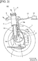
Figure 3 ] is a side view illustrating a state in which the unsprung power supply apparatus for an in-wheel motor vehicle of a second embodiment is viewed from an inner side of the wheel. - [
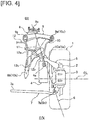
Figure 4 ] is a front view illustrating a state in which the unsprung power supply apparatus for an in-wheel motor vehicle of the second embodiment is viewed from a front of the wheel. - [
Figure 5 ] is a side view illustrating a state in which the unsprung power supply apparatus for an in-wheel motor vehicle of a third embodiment is viewed from an inner side of the wheel. - [
Figure 6 ] is a front view illustrating a state in which the unsprung power supply apparatus for an in-wheel motor vehicle of the third embodiment is viewed from a front of the wheel. - [
Figure 7 ] is a cross sectional view taken along line A-A ofFigure 6 , illustrating the positions of the motor power supply terminals in the unsprung power supply apparatus for an in-wheel motor vehicle of a comparative example. - [
Figure 8 ] is a cross sectional view taken along line A-A ofFigure 6 , illustrating the positions of the motor power supply terminals corresponding to steering in the unsprung power supply apparatus for an in-wheel motor vehicle of a comparative example. - [
Figure 9 ] is a cross sectional view taken along line A-A ofFigure 6 , illustrating the positions of the motor power supply terminals in the unsprung power supply apparatus for an in-wheel motor vehicle of a fourth embodiment. - [
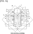
Figure 10 ] is a cross sectional view taken along line A-A ofFigure 6 , illustrating the positions of the motor power supply terminals corresponding to steering in the unsprung power supply apparatus for an in-wheel motor vehicle of the fourth embodiment. - Preferred embodiments for realizing the unsprung power supply apparatus for an in-wheel motor vehicle of the present invention will be described below based on the first to the fourth embodiments illustrated in the drawings.
-
Figure 1 andFigure 2 illustrate a state in which an unsprung power supply apparatus B1 for an in-wheel motor vehicle of the first embodiment is viewed from the inner side of the wheel and from the front of the wheel. The configuration of the unsprung power supply apparatus B1 for an in-wheel motor vehicle will be described below, based onFigure 1 andFigure 2 . - An in-wheel motor vehicle to which is applied the above-described unsprung power supply apparatus B1 comprises a tire 1, a
brake disk 2, abrake caliper 3, an in-wheel motor 4, asteering knuckle 5, avirtual kingpin axis 6, alower link 7, a shock absorber 8, anupper link 9, and athird link 10, as illustrated inFigure 1 andFigure 2 . That is, thesteering knuckle 5 is provided for turning a tire 1, and is provided with the in-wheel motor 4 and thethird link 10 such that thevirtual kingpin axis 6 is an axis passing through a knuckleside coupling point 10a at which is coupled to thesteering knuckle 5. - The
virtual kingpin axis 6 described above is a virtual axis that connects a knuckleside coupling point 10a (= an upper end of thesteering knuckle 5a) of thethird link 10 and thesteering knuckle 5, and a motor-side pivot point 7b (- a lower end of thesteering knuckle 5b) of thelower link 7. The tire 1 is steered around thevirtual kingpin axis 6 by a steering mechanism, such as a tie rod, which is not shown. - The tire 1 is incorporated on a wheel, which is not shown, and the
brake disc 2 as well as thesteering knuckle 5, and the in-wheel motor 4 via a hub, which is not shown, are incorporated in the wheel along a wheel axis CL. - The
lower link 7 is a first suspension link member that connects the vehicle body and thesteering knuckle 5 on the lower side of the wheel axis CL. Thislower link 7 incorporates a vehicle body-side pivot shaft 7a so as to be pivotable with respect to the vehicle body, which is not shown, and incorporates the motor-side pivot point 7b on the other end so as to be rotatable with respect to the knucklelower end 5b of thesteering knuckle 5. - The
shock absorber 8 is a strut structure in which a shock absorber and a coil spring are coaxially arranged, and is a suspension member that is supported on the vehicle body while buffering the force that is received in the vertical direction of the vehicle. The shock absorber 8 elastically supports anupper end 8a of the shock absorber with respect to the vehicle body, which is not shown, and incorporates alower end 8b of the shock absorber shaft so as to be pivotable with respect to the shaft-side coupling point 10b of thethird link 10. - The
upper link 9 is a second suspension link member that connects the vehicle body and thethird link 10 on the upper side of the wheel axis CL. Thisupper link 9 incorporates the vehicle body-side pivot shaft 9a so as to be pivotable with respect to a vehicle body side member, which is not shown, and incorporates a third link-side pivot point 9b on the other end so as to be pivotable with respect to a link-side coupling point 10c of thethird link 10. - The
third link 10 is a third suspension link member that connects theupper link 9 and thesteering knuckle 5. Thethird link 10 incorporates the knuckle-side coupling point 10a so as to be rotatable with respect to thesteering knuckle 5 around thevirtual kingpin axis 6. The third link further incorporates the shaft-side coupling point 10b so as to be pivotable with respect to the shock absorber shaftlower end 8b of theshock absorber 8, and incorporates the link-side coupling point 10c so as to be pivotable with respect to the third link-side pivot point 9b of theupper link 9. - The unsprung power supply apparatus B1 comprises a power supply
cable fixing member 11 and apower supply cable 12, as illustrated inFigure 1 andFigure 2 . Then, part of thepower supply cable 12 that connects the in-wheel motor 4 and the vehicle body sidepower supply unit 14 for wiring is fixed to thethird link 10, by the power supplycable fixing member 11. - The
power supply cable 12 is split into a vehicle body-sidepower supply cable 12a and a motor-sidepower supply cable 12b, at the fixing position to thethird link 10. Then, the vehicle body-sidepower supply cable 12a is provided with a slack 12c in the power supply cable as play that accommodates the vertical movement caused by bounding/rebounding. The motor-sidepower supply cable 12b is only provided with the minimum play in the power supply cable, with which it is possible to mainly accommodate the rotational movement by steering the tire, and connects the end portion of the motor-sidepower supply cable 12b to the motorpower supply terminal 4a of the in-wheel motor 4. - When the tire 1 is steered around the
virtual kingpin axis 6, thesteering knuckle 5, the in-wheel motor 4, and the motor-sidepower supply cable 12b are integrally steered together therewith. In addition, each part incorporated in theupper link 9 and thelower link 7 carries out bounding and rebounding within a set range of the shock absorber 8, with the vehicle body-side pivot shaft 9a and the vehicle body-side pivot shaft 7a as axes of the pivoting movement. - Next, the actions are described.
- The first embodiment is configured such that a part of the
power supply cable 12 that connects the in-wheel motor 4 and the vehicle body-sidepower supply unit 14 for wiring is fixed to thethird link 10. - That is, the
third link 10 is highly rigid, and also is a non-rotating link member that is coupled with theesteering knuckle 5 such that the virtual kingpin axis 6 (steering rotational axis), passes through the knuckleside coupling point 10a. Accordingly, thepower supply cable 12 that is fixed to thethird link 10 is split into the vehicle body-sidepower supply cable 12a and the motor-sidepower supply cable 12b, at the fixing position to thethird link 10. Further, there is basically only a vertical movement accompanying bounding/rebounding on the side with the vehicle body-sidepower supply cable 12a, and there is no rotational movement during steering. On the other hand, there is basically only a rotational movement during steering on the side with the motor-sidepower supply cable 12b, and there is no vertical movement, even if there is bounding/rebounding. - Accordingly, the vehicle body-side
power supply cable 12a needs only to accommodate the vertical movement caused by bounding/rebounding, and the motor-sidepower supply cable 12b needs only to accommodate the rotational movement caused by tire steering; thus, the motion absorption functions are divided. That is, the vehicle body-sidepower supply cable 12a is provided with slack 12c in the power supply cable as play that accommodates the vertical movement, and the motor-sidepower supply cable 12b is only provided with minimum play with which it is possible to accommodate the rotational movement. - Therefore, during bounding/rebounding, since only the power
supply cable slack 12c of the vehicle body-sidepower supply cable 12a changes shape and is displaced in the vertical direction of the vehicle, the space where the power supply cable swings is a narrow space defined by simply expanding the powersupply cable slack 12c in the vertical direction. Additionally, during steering, since the motor-sidepower supply cable 12b is torsionally displaced according to the steering angle, the space where the power supply cable swings is a limited narrow space surrounding the motor-sidepower supply cable 12b. In the same manner, even if bounding/rebounding and steering overlap each other, the vehicle body-sidepower supply cable 12a accommodates the vertical movement and the motor-sidepower supply cable 12b accommodates the rotational movement, displaying a movement absorption action by division of functions. - In this manner, in the
power supply cable 12, the movement accommodating functions are divided between the vehicle body-sidepower supply cable 12a and the motor-sidepower supply cable 12b. Accordingly, compared with determining the total length of the power supply cable so as to accommodate the combined motion of the vertical movement and the rotational movement, it is possible to shorten the total length of thepower supply cable 12 and to decrease the space (dead space) in which the cable swings. As a result, the space where thepower supply cable 12 for an in-wheel motor 4 swings can be decreased while keeping a simple structure, in which a part of thepower supply cable 12 is simply fixed to thethird link 10 by the power supplycable fixing member 11. - Next, the effects are described.
- In the unsprung power supply apparatus B1 for an in-wheel motor vehicle according to the first embodiment, the following effects can be achieved:
- (1) In an in-wheel motor vehicle, a
steering knuckle 5 for turning a tire 1 is provided with an in-wheel motor 4 and athird link 10, and a virtual king-pin axis 6 is an axis passing through a coupling point (knuckleside coupling point 10a) at which thesteering knuckle 5 is coupled; and - Accordingly, it is possible to decrease the space where the
power supply cable 12 for an in-wheel motor 4 swings while keeping a simple structure. - The second embodiment is an example in which the fixing position of the power supply cable to the third link is defined in a position in the vicinity of the virtual kingpin axis.
-
Figure 3 andFigure 4 illustrate a state in which the unsprung power supply apparatus B2 for an in-wheel motor vehicle of the second embodiment is viewed from the inner side of the wheel and from the front of the wheel. The configuration and the action of the unsprung power supply apparatus B2 for an in-wheel motor vehicle will be described below, based onFigure 3 andFigure 4 . - An in-wheel motor vehicle to which is applied the above-described unsprung power supply apparatus B2 comprises the tire 1, the
brake disk 2, thebrake caliper 3, the in-wheel motor 4, thesteering knuckle 5, thevirtual kingpin axis 6, thelower link 7, theshock absorber 8, theupper link 9, and thethird link 10, as illustrated inFigure 3 andFigure 4 . - The unsprung power supply apparatus B1 comprises the power supply
cable fixing member 11 and thepower supply cable 12, as illustrated inFigure 3 andFigure 4 . The part of thepower supply cable 12 that connects the in-wheel motor 4 and the vehicle body-sidepower supply unit 14 for wiring, is fixed on thethird link 10 at a position in the vicinity of thevirtual kingpin axis 6 on thethird link 10. That is, when viewed from the front, the power supplycable fixing member 11 is provided at a position that overlaps thevirtual kingpin axis 6 on an outer side position of thethird link 10, as illustrated inFigure 4 . The position in the vicinity of thevirtual kingpin axis 6 includes a position that coincides with thevirtual kingpin axis 6, and a position in which the distance from thevirtual kingpin axis 6 is within the range of a set distance. - In this manner, the second embodiment is configured such that, when a part of the
power supply cable 12 that connects the in-wheel motor 4 and the vehicle body-sidepower supply unit 14 for wiring is fixed to thethird link 10, the power supply cable is fixed in a position in the vicinity of thevirtual kingpin axis 6. Accordingly, the amount of change of the relative position of the power supplycable fixing member 11 that is fixed to the in-wheel motor 4 and thethird link 10 is reduced during steering, and the wiring of the motor-sidepower supply cable 12b can be arranged in a compact manner. The other configurations and actions are the same as in the first embodiment, so the descriptions thereof are omitted. - Next, the effects are described.
- In the unsprung power supply apparatus B2 for an in-wheel motor vehicle according to the second embodiment, the following effects can be achieved:
- (2) The part of the
power supply cable 12 for wiring is fixed to thethird link 10 in a position in a vicinity of the virtual kingpin axis 6 (Figure 4 ). - Accordingly, in addition to the effect of (1), compared to the case in which the power supply cable is fixed in a position of the
third link 10 away from thevirtual kingpin axis 6, the wiring of the motor-sidepower supply cable 12b can be arranged in a compact manner. - The third embodiment is an example in which the fixing positions to the third link are defined when wiring two or more power supply cables.
-
Figure 5 andFigure 6 illustrate a state in which the unsprung power supply apparatus B3 for an in-wheel motor vehicle of the third embodiment is viewed from the inner side of the wheel and from the front of the wheel. The configuration and the action of the unsprung power supply apparatus B3 for an in-wheel motor vehicle will be described below, based onFigure 5 andFigure 6 . The configuration is described. - The in-wheel motor vehicle to which is applied the above-described unsprung power supply apparatus B3 comprises the tire I, the
brake disk 2, thebrake caliper 3, the in-wheel motor 4, thesteering knuckle 5, thevirtual kingpin axis 6, thelower link 7, theshock absorber 8, theupper link 9 and thethird link 10, as illustrated inFigure 5 andFigure 6 . - The
third link 10 supports the lower end of theshock absorber 8 at the shaft-side coupling point 10b, which is in a position that is further on the vehicle body-side than the knuckleside coupling point 10a, as illustrated inFigure 5 . The third link is further configured to comprise a front link portion 10d and a rear link portion 10e so as to sandwich theshock absorber 8 in the longitudinal direction of the vehicle. - The unsprung power supply apparatus B3 described above comprises two power supply
cable fixing members power supply cables Figure 5 andFigure 6 . Then, the parts of the twopower supply cables wheel motor 4 and the vehicle body-sidepower supply unit 14 are respectively fixed to the outer sides of the front link portion 10d and the rear link portion 10e by the power supplycable fixing members - In this manner, in the third embodiment, when wiring two or more
power supply cables 12 which connect the in-wheel motor 4 and the vehicle body-sidepower supply unit 14 to thethird link 10, the power supply cables sandwich theshock absorber 8, and are fixed to the front and read link portions 10d, 10e of thethird link 10, which are rigid members. Accordingly, it is possible to prevent interference between two thickpower supply cables shock absorber 8 therebetween. The other configurations and actions are the same as the first embodiment, so the descriptions thereof are omitted. - Next, the effects are described.
- In the unsprung power supply apparatus B3 for an in-wheel motor vehicle according to the third embodiment, the following effects can be achieved:
- (3) The
third link 10 is configured so as to support the lower end of theshock absorber 8 in a position that is further on the vehicle body-side than the joint of the steering knuckle 5 (knuckleside coupling point 10a), and comprises a front link portion 10d and a rear link portion 10e so as to sandwich theshock absorber 8 in the longitudinal direction of the vehicle. - When there are two or more
power supply cables wheel motor 4 and the vehicle body-sidepower supply cable 14, the power supply cables are respectively fixed to the outer sides of the front link portion and the rear link portion (Figure 5 ). - Accordingly, in addition to the effects of (1) or (2) above, when two or more
power supply cables power supply cables shock absorber 8 between thepower supply cables - The fourth embodiment is an example in which a measure is taken to prevent a part of the motor-side power supply cable from entering below the third link during steering.
-
Figure 7 illustrates the positions of the motor power supply terminals in the unsprung power supply apparatus for an in-wheel motor vehicle of a comparative example, andFigure 8 illustrates the positions of the motor power supply terminals corresponding to steering. The problem in an unsprung power supply apparatus for an in-wheel motor vehicle of a comparative example will be described below, based onFigure 7 andFigure 8 . - In the case of the comparative example, when disposing two
power supply cables third link 10, two straight lines L1, L2 that respectively connect thevirtual kingpin axis 6 and the two motorpower supply terminals Figure 7 . Then, power supplycable fixing members - In the case of this comparative example, when the tire 1 is steered around the
virtual kingpin axis 6, thesteering knuckle 5, the in-wheel motor 4, and the motor-sidepower supply cable 12b are integrally steered together therewith. Consequently, a part of the motor-sidepower supply cable 12b and the motorpower supply terminal 4a overlap and enter below thethird link 10 during steering, as illustrated inFigure 8 . As a result, when overlapped below thethird link 10, it is necessary to avoid interference between the motor-sidepower supply cable 12b and the in-wheel motor 4, and between the motor-sidepower supply cable 12b and thethird link 10, and thus, an increase in the motor size of the in-wheel motor 4 or a reduction in the size of thethird link 10 cannot be expected. -
Figure 9 illustrates the positions of the motor power supply terminals in the unsprung power supply apparatus B4 for an in-wheel motor vehicle of the fourth embodiment, andFigure 10 illustrates the positions of the motor power supply terminals corresponding to steering. The configuration and the action of the unsprung power supply apparatus B4 for an in-wheel motor vehicle of the fourth embodiment will be described below, based onFigure 9 andFigure 10 . - In the unsprung power supply apparatus B4 described above, the parts of the two
power supply cables 12 are respectively fixed to the outer sides of the front link portion 10d and the rear link portion 10e by the power supplycable fixing members Figure 9 . When the tire is in a straight state, one straight line that connects thevirtual kingpin axis 6 and the two motorpower supply terminals wheel motor 4 is set as a common axis L0. Then, the two power supplycable fixing members third link 10 are configured to be disposed in a position in the vicinity of the common axis L0. - In the case of the fourth embodiment, a part of the motor-side
power supply cable 12b and the motorpower supply terminal 4a do not overlap and enter below thethird link 10 during steering, as illustrated inFigure 10 . As a result, the problem of interferences between the motor-sidepower supply cable 12b and the in-wheel motor 4, and between the motor-sidepower supply cable 12b and thethird link 10 do not occur, and thus, it is possible to expect an increase in the motor size of the in-wheel motor 4 and a reduction in the size of thethird link 10. The other configurations and actions are the same as the first embodiment, so the descriptions thereof are omitted. - Next, the effects are described.
- In the unsprung power supply apparatus B4 for an in-wheel motor vehicle according to the fourth embodiment, the following effects can be achieved:
- (4) When the tire 1 is straight, one straight line that connects the
virtual kingpin axis 6 and the two motorpower supply terminals wheel motor 4 are set as a common axis L0; and, - Accordingly, in addition to the effect of (3) above, it is possible to expect an increase in the motor size of the in-
wheel motor 4 and a reduction in the size of thethird link 10. - The unsprung power supply apparatus for an in-wheel motor vehicle of the present invention was described above based on the first to fourth embodiments, but specific configurations thereof are not limited to these embodiments, and various modifications and additions to the design can be made without departing from the scope of the invention according to each claim in the Claims.
- In the first to fourth embodiments, the unsprung power supply apparatus of the present invention is applied to an in-wheel motor vehicle provided with an upper link, a lower link, a third link, and a shock absorber as suspension members. However, the unsprung power supply apparatus of the present invention can be applied to an in-wheel motor vehicle provided with a suspension having a different linking structure. That is, the device can be applied to any in-wheel motor vehicle that is equipped with a third link that is provided to a knuckle, and that has, as a virtual king-pin axis, an axis that passes through a coupling point with the knuckle.
- This application claims right of priority based on Japanese Patent Application No.
2014-133315
Claims (4)
- An unsprung power supply apparatus for an in-wheel motor vehicle, comprising:a steering knuckle for steering a tire of the in-wheel motor vehicle is provided with an in-wheel motor and a third link, and a virtual kingpin axis is an axis passing through a coupling point at which the third link couples with the steering knuckle; anda power supply cable connecting the in-wheel motor and a vehicle body-side power supply unit for wiring, with a part being fixed to the third link.
- The unsprung power supply apparatus for an in-wheel motor vehicle according to claim 1, wherein
the part of the power supply cable for wiring is fixed to the third link in a position in a vicinity of the virtual kingpin axis. - The unsprung power supply apparatus for an in-wheel motor vehicle according to claim 1 or 2, wherein
the third link is configured to support a lower end of a shock absorber in a position that is further on a vehicle body side than a joint with the steering knuckle, and comprises a front link portion and a rear link portion that sandwiches the shock absorber in a longitudinal direction of the vehicle; and
when two or more power supply cables are provided which connect the in-wheel motor and a vehicle body-side power supply cable, the power supply cables are respectively fixed to outer sides of the front link portion and the rear link portion. - The unsprung power supply apparatus for an in-wheel motor vehicle according to claim 3, wherein
when the tire is in a straight state, one straight line that connects the virtual kingpin axis and two motor power supply terminals of the in-wheel motor are set as a common axis; and
two power supply cable fixing members are fixed to outer sides of the front link portion and the rear link portion of the third link at positions in a vicinity of the common axis.
Applications Claiming Priority (2)
| Application Number | Priority Date | Filing Date | Title |
|---|---|---|---|
| JP2014133315 | 2014-06-27 | ||
| PCT/JP2015/060838 WO2015198679A1 (en) | 2014-06-27 | 2015-04-07 | Unsprung power supply apparatus for in-wheel motor vehicle |
Publications (3)
| Publication Number | Publication Date |
|---|---|
| EP3162607A1 true EP3162607A1 (en) | 2017-05-03 |
| EP3162607A4 EP3162607A4 (en) | 2017-05-24 |
| EP3162607B1 EP3162607B1 (en) | 2019-03-13 |
Family
ID=54937780
Family Applications (1)
| Application Number | Title | Priority Date | Filing Date |
|---|---|---|---|
| EP15812195.4A Active EP3162607B1 (en) | 2014-06-27 | 2015-04-07 | Unsprung power supply apparatus for in-wheel motor vehicle |
Country Status (5)
| Country | Link |
|---|---|
| US (1) | US10059162B2 (en) |
| EP (1) | EP3162607B1 (en) |
| JP (1) | JP6323555B2 (en) |
| CN (1) | CN106470862B (en) |
| WO (1) | WO2015198679A1 (en) |
Families Citing this family (10)
| Publication number | Priority date | Publication date | Assignee | Title |
|---|---|---|---|---|
| FR3021910B1 (en) * | 2014-06-05 | 2018-12-07 | Valeo Systemes De Controle Moteur | STATOR ASSEMBLY FOR WHEEL MOTOR AND ITS RACK HOLDER. |
| EP3162607B1 (en) * | 2014-06-27 | 2019-03-13 | Nissan Motor Co., Ltd | Unsprung power supply apparatus for in-wheel motor vehicle |
| JP6334590B2 (en) * | 2016-04-06 | 2018-05-30 | Ntn株式会社 | In-wheel motor drive device |
| JP6918459B2 (en) * | 2016-04-06 | 2021-08-11 | Ntn株式会社 | Wiring structure of in-wheel motor power line and in-wheel motor drive |
| JP2017185912A (en) * | 2016-04-06 | 2017-10-12 | Ntn株式会社 | Wiring structure of in-wheel motor power line and in-wheel motor driving device |
| CN107848399B (en) * | 2016-04-06 | 2022-04-15 | Ntn株式会社 | In-wheel motor power line wiring structure and in-wheel motor drive device |
| JP2019006265A (en) * | 2017-06-26 | 2019-01-17 | Ntn株式会社 | Wiring structure of in-wheel motor power line |
| JP7004121B2 (en) * | 2020-02-20 | 2022-02-10 | 住友電装株式会社 | Wire harness and wire harness wiring structure |
| JP7082997B2 (en) * | 2020-03-16 | 2022-06-09 | 本田技研工業株式会社 | Saddle-mounted electric tricycle |
| JP7753887B2 (en) * | 2022-01-12 | 2025-10-15 | 住友電装株式会社 | Undercarriage wiring module |
Family Cites Families (35)
| Publication number | Priority date | Publication date | Assignee | Title |
|---|---|---|---|---|
| US3163250A (en) * | 1960-06-09 | 1964-12-29 | Raymond Corp | Narrow aisle material handling truck |
| US3566165A (en) * | 1969-05-06 | 1971-02-23 | Gen Motors Corp | Electric vehicle drive motor |
| JP2554697B2 (en) * | 1988-03-29 | 1996-11-13 | 新日本製鐵株式会社 | Electric vehicle motor cooling system |
| JPH03112724A (en) | 1989-09-25 | 1991-05-14 | Aisin Aw Co Ltd | Wiring for vehicle motor and piping device |
| US5150763A (en) * | 1991-04-24 | 1992-09-29 | Aisin Aw Co., Ltd. | Wiring and piping arrangement for a vehicle motor |
| US5087229A (en) * | 1991-05-06 | 1992-02-11 | General Motors Corporation | Independently suspended steerable motor wheel apparatus |
| US5327034A (en) * | 1992-07-14 | 1994-07-05 | Hydro-Quebec | Electrically motorized wheel assembly |
| DE9305633U1 (en) * | 1993-04-15 | 1993-06-17 | EC Engineering + Consulting Spezialmaschinen GmbH, 7900 Ulm | Device for driving, guiding and steering a vehicle wheel |
| JP3440082B2 (en) * | 2001-02-19 | 2003-08-25 | 科学技術振興事業団 | In-wheel motor for electric vehicles |
| JP4154883B2 (en) * | 2001-11-01 | 2008-09-24 | 株式会社日立製作所 | Brake device |
| US7597169B2 (en) * | 2001-12-07 | 2009-10-06 | Gm Global Technology Operations, Inc. | Wheel module |
| US7413203B2 (en) * | 2003-05-14 | 2008-08-19 | Toyota Jidosha Kabushiki Kaisha | Suspension system for electric vehicle |
| JP4276579B2 (en) * | 2004-05-17 | 2009-06-10 | トヨタ自動車株式会社 | Mounting structure of components installed in in-wheel motor |
| JP2005329910A (en) * | 2004-05-21 | 2005-12-02 | Bridgestone Corp | In-wheel motor system |
| JP2006240429A (en) * | 2005-03-02 | 2006-09-14 | Toyota Motor Corp | Drive unit |
| JP4965131B2 (en) * | 2006-01-27 | 2012-07-04 | トヨタ自動車株式会社 | In-wheel motor |
| US7849945B2 (en) * | 2006-02-24 | 2010-12-14 | Honda Motor Co., Ltd | Modular electric powertrain for a vehicle |
| JP2008001241A (en) | 2006-06-22 | 2008-01-10 | Toyota Motor Corp | Wire wiring structure |
| US20110011656A1 (en) * | 2007-03-20 | 2011-01-20 | Peder Ulrik Poulsen | Hybrid vehicle system with indirect drive |
| US20080257620A1 (en) * | 2007-03-20 | 2008-10-23 | Peder Ulrik Poulsen | Hybrid Vehicle Drive System |
| EP2150429B1 (en) * | 2007-05-18 | 2013-01-16 | Materialwerks LLC | Road wheel propulsion apparatus and method of making |
| JP5252840B2 (en) | 2007-06-14 | 2013-07-31 | トヨタ自動車株式会社 | Wheel drive device |
| JP4780170B2 (en) * | 2008-09-30 | 2011-09-28 | トヨタ自動車株式会社 | Vehicle motor drive device |
| JP5393285B2 (en) * | 2009-06-18 | 2014-01-22 | アイシン精機株式会社 | Wiring structure and wiring method of electric motor |
| JP5383340B2 (en) * | 2009-06-18 | 2014-01-08 | アイシン精機株式会社 | Wiring structure and wiring method of electric motor |
| US8746383B2 (en) * | 2010-03-01 | 2014-06-10 | Victor Basadzishvili | Vehicle suspension and drive system |
| JP5848105B2 (en) * | 2011-11-25 | 2016-01-27 | Ntn株式会社 | Conductive path of electric vehicle |
| JP2013144509A (en) * | 2012-01-16 | 2013-07-25 | Nissan Motor Co Ltd | Motor feeder wiring structure of in-wheel motor driving wheel |
| JP5891803B2 (en) * | 2012-01-18 | 2016-03-23 | 日産自動車株式会社 | Steering wheel wire harness wiring structure |
| JP2013159224A (en) * | 2012-02-06 | 2013-08-19 | Nissan Motor Co Ltd | Wire harness routing structure of power source integration type wheel |
| JP5892072B2 (en) * | 2013-01-08 | 2016-03-23 | 日立金属株式会社 | Composite cable for vehicles |
| US9302577B2 (en) * | 2013-08-29 | 2016-04-05 | Roberto Sanchez Catalan | Halbach array electric motor with substantially contiguous electromagnetic cores |
| JP6271196B2 (en) * | 2013-09-19 | 2018-01-31 | Ntn株式会社 | In-wheel motor drive device |
| EP3162607B1 (en) * | 2014-06-27 | 2019-03-13 | Nissan Motor Co., Ltd | Unsprung power supply apparatus for in-wheel motor vehicle |
| JP6219263B2 (en) * | 2014-12-22 | 2017-10-25 | 日立金属株式会社 | Composite cable for vehicle and composite harness for vehicle |
-
2015
- 2015-04-07 EP EP15812195.4A patent/EP3162607B1/en active Active
- 2015-04-07 JP JP2016529124A patent/JP6323555B2/en active Active
- 2015-04-07 US US15/314,998 patent/US10059162B2/en active Active
- 2015-04-07 WO PCT/JP2015/060838 patent/WO2015198679A1/en not_active Ceased
- 2015-04-07 CN CN201580034589.XA patent/CN106470862B/en active Active
Also Published As
| Publication number | Publication date |
|---|---|
| CN106470862B (en) | 2018-10-30 |
| WO2015198679A1 (en) | 2015-12-30 |
| JPWO2015198679A1 (en) | 2017-04-20 |
| CN106470862A (en) | 2017-03-01 |
| EP3162607A4 (en) | 2017-05-24 |
| EP3162607B1 (en) | 2019-03-13 |
| JP6323555B2 (en) | 2018-05-16 |
| US20170190229A1 (en) | 2017-07-06 |
| US10059162B2 (en) | 2018-08-28 |
Similar Documents
| Publication | Publication Date | Title |
|---|---|---|
| EP3162607B1 (en) | Unsprung power supply apparatus for in-wheel motor vehicle | |
| CN105163961B (en) | In-wheel motor driving moment draft hitch | |
| CN102717696B (en) | Independent driving, steering and suspending system | |
| US9796235B2 (en) | Suspension device for in-wheel motor driven wheel | |
| CN103917434A (en) | Steering device for wheel | |
| US20190329621A1 (en) | Vehicle suspension system | |
| JP7163857B2 (en) | In-wheel motor unit connection structure | |
| JP7834426B2 (en) | Wiring module for undercarriage and wiring structure for undercarriage wiring module | |
| JP2015020586A (en) | Suspension device | |
| US20160149357A1 (en) | Motor power feed wiring routing structure for in-wheel motor driven wheel | |
| JP2013144509A (en) | Motor feeder wiring structure of in-wheel motor driving wheel | |
| CN107757704B (en) | Vehicle Steering Control Systems and Vehicles | |
| CN103358840A (en) | Electric vehicle | |
| CN108749554A (en) | With the matched electric automobile hub power drive system of independent suspension | |
| JP6365008B2 (en) | Vehicle suspension system | |
| JP2015013528A (en) | Motor power feed wire cabling structure of in-wheel motor drive wheel | |
| CN203844833U (en) | Construction machine and steering mechanism thereof | |
| JP7456315B2 (en) | Wheel side equipment and undercarriage wiring equipment | |
| JP6331770B2 (en) | In-wheel motor steered wheel suspension system | |
| CN115867451A (en) | Chassis wiring module and wiring structure of chassis wiring module | |
| US20250087983A1 (en) | Suspension wiring module | |
| CN108137094B (en) | Wheel suspension for steerable wheels for dual-rut vehicles | |
| JP2007038913A (en) | Suspension device and suspension device design method | |
| GB2575011A (en) | Suspension system | |
| JP2009137477A (en) | Steering device |
Legal Events
| Date | Code | Title | Description |
|---|---|---|---|
| STAA | Information on the status of an ep patent application or granted ep patent |
Free format text: STATUS: THE INTERNATIONAL PUBLICATION HAS BEEN MADE |
|
| PUAI | Public reference made under article 153(3) epc to a published international application that has entered the european phase |
Free format text: ORIGINAL CODE: 0009012 |
|
| STAA | Information on the status of an ep patent application or granted ep patent |
Free format text: STATUS: REQUEST FOR EXAMINATION WAS MADE |
|
| 17P | Request for examination filed |
Effective date: 20170119 |
|
| AK | Designated contracting states |
Kind code of ref document: A1 Designated state(s): AL AT BE BG CH CY CZ DE DK EE ES FI FR GB GR HR HU IE IS IT LI LT LU LV MC MK MT NL NO PL PT RO RS SE SI SK SM TR |
|
| AX | Request for extension of the european patent |
Extension state: BA ME |
|
| A4 | Supplementary search report drawn up and despatched |
Effective date: 20170426 |
|
| RIC1 | Information provided on ipc code assigned before grant |
Ipc: B60G 3/20 20060101ALI20170420BHEP Ipc: B60K 7/00 20060101AFI20170420BHEP Ipc: H02G 11/00 20060101ALI20170420BHEP |
|
| DAV | Request for validation of the european patent (deleted) | ||
| DAX | Request for extension of the european patent (deleted) | ||
| GRAP | Despatch of communication of intention to grant a patent |
Free format text: ORIGINAL CODE: EPIDOSNIGR1 |
|
| STAA | Information on the status of an ep patent application or granted ep patent |
Free format text: STATUS: GRANT OF PATENT IS INTENDED |
|
| RIC1 | Information provided on ipc code assigned before grant |
Ipc: B60K 1/00 20060101ALI20180411BHEP Ipc: B60G 3/20 20060101ALI20180411BHEP Ipc: H02G 11/00 20060101ALI20180411BHEP Ipc: B60K 7/00 20060101AFI20180411BHEP Ipc: B60R 16/02 20060101ALI20180411BHEP Ipc: B60L 11/18 20060101ALI20180411BHEP |
|
| INTG | Intention to grant announced |
Effective date: 20180516 |
|
| GRAJ | Information related to disapproval of communication of intention to grant by the applicant or resumption of examination proceedings by the epo deleted |
Free format text: ORIGINAL CODE: EPIDOSDIGR1 |
|
| STAA | Information on the status of an ep patent application or granted ep patent |
Free format text: STATUS: REQUEST FOR EXAMINATION WAS MADE |
|
| GRAP | Despatch of communication of intention to grant a patent |
Free format text: ORIGINAL CODE: EPIDOSNIGR1 |
|
| STAA | Information on the status of an ep patent application or granted ep patent |
Free format text: STATUS: GRANT OF PATENT IS INTENDED |
|
| INTG | Intention to grant announced |
Effective date: 20181115 |
|
| GRAS | Grant fee paid |
Free format text: ORIGINAL CODE: EPIDOSNIGR3 |
|
| GRAA | (expected) grant |
Free format text: ORIGINAL CODE: 0009210 |
|
| STAA | Information on the status of an ep patent application or granted ep patent |
Free format text: STATUS: THE PATENT HAS BEEN GRANTED |
|
| AK | Designated contracting states |
Kind code of ref document: B1 Designated state(s): AL AT BE BG CH CY CZ DE DK EE ES FI FR GB GR HR HU IE IS IT LI LT LU LV MC MK MT NL NO PL PT RO RS SE SI SK SM TR |
|
| REG | Reference to a national code |
Ref country code: GB Ref legal event code: FG4D |
|
| REG | Reference to a national code |
Ref country code: CH Ref legal event code: EP Ref country code: AT Ref legal event code: REF Ref document number: 1107225 Country of ref document: AT Kind code of ref document: T Effective date: 20190315 |
|
| REG | Reference to a national code |
Ref country code: IE Ref legal event code: FG4D |
|
| REG | Reference to a national code |
Ref country code: DE Ref legal event code: R096 Ref document number: 602015026508 Country of ref document: DE |
|
| REG | Reference to a national code |
Ref country code: NL Ref legal event code: MP Effective date: 20190313 |
|
| REG | Reference to a national code |
Ref country code: LT Ref legal event code: MG4D |
|
| PG25 | Lapsed in a contracting state [announced via postgrant information from national office to epo] |
Ref country code: NO Free format text: LAPSE BECAUSE OF FAILURE TO SUBMIT A TRANSLATION OF THE DESCRIPTION OR TO PAY THE FEE WITHIN THE PRESCRIBED TIME-LIMIT Effective date: 20190613 Ref country code: LT Free format text: LAPSE BECAUSE OF FAILURE TO SUBMIT A TRANSLATION OF THE DESCRIPTION OR TO PAY THE FEE WITHIN THE PRESCRIBED TIME-LIMIT Effective date: 20190313 Ref country code: SE Free format text: LAPSE BECAUSE OF FAILURE TO SUBMIT A TRANSLATION OF THE DESCRIPTION OR TO PAY THE FEE WITHIN THE PRESCRIBED TIME-LIMIT Effective date: 20190313 Ref country code: FI Free format text: LAPSE BECAUSE OF FAILURE TO SUBMIT A TRANSLATION OF THE DESCRIPTION OR TO PAY THE FEE WITHIN THE PRESCRIBED TIME-LIMIT Effective date: 20190313 |
|
| PG25 | Lapsed in a contracting state [announced via postgrant information from national office to epo] |
Ref country code: RS Free format text: LAPSE BECAUSE OF FAILURE TO SUBMIT A TRANSLATION OF THE DESCRIPTION OR TO PAY THE FEE WITHIN THE PRESCRIBED TIME-LIMIT Effective date: 20190313 Ref country code: NL Free format text: LAPSE BECAUSE OF FAILURE TO SUBMIT A TRANSLATION OF THE DESCRIPTION OR TO PAY THE FEE WITHIN THE PRESCRIBED TIME-LIMIT Effective date: 20190313 Ref country code: BG Free format text: LAPSE BECAUSE OF FAILURE TO SUBMIT A TRANSLATION OF THE DESCRIPTION OR TO PAY THE FEE WITHIN THE PRESCRIBED TIME-LIMIT Effective date: 20190613 Ref country code: LV Free format text: LAPSE BECAUSE OF FAILURE TO SUBMIT A TRANSLATION OF THE DESCRIPTION OR TO PAY THE FEE WITHIN THE PRESCRIBED TIME-LIMIT Effective date: 20190313 Ref country code: GR Free format text: LAPSE BECAUSE OF FAILURE TO SUBMIT A TRANSLATION OF THE DESCRIPTION OR TO PAY THE FEE WITHIN THE PRESCRIBED TIME-LIMIT Effective date: 20190614 Ref country code: HR Free format text: LAPSE BECAUSE OF FAILURE TO SUBMIT A TRANSLATION OF THE DESCRIPTION OR TO PAY THE FEE WITHIN THE PRESCRIBED TIME-LIMIT Effective date: 20190313 |
|
| REG | Reference to a national code |
Ref country code: AT Ref legal event code: MK05 Ref document number: 1107225 Country of ref document: AT Kind code of ref document: T Effective date: 20190313 |
|
| PG25 | Lapsed in a contracting state [announced via postgrant information from national office to epo] |
Ref country code: IT Free format text: LAPSE BECAUSE OF FAILURE TO SUBMIT A TRANSLATION OF THE DESCRIPTION OR TO PAY THE FEE WITHIN THE PRESCRIBED TIME-LIMIT Effective date: 20190313 Ref country code: EE Free format text: LAPSE BECAUSE OF FAILURE TO SUBMIT A TRANSLATION OF THE DESCRIPTION OR TO PAY THE FEE WITHIN THE PRESCRIBED TIME-LIMIT Effective date: 20190313 Ref country code: SK Free format text: LAPSE BECAUSE OF FAILURE TO SUBMIT A TRANSLATION OF THE DESCRIPTION OR TO PAY THE FEE WITHIN THE PRESCRIBED TIME-LIMIT Effective date: 20190313 Ref country code: PT Free format text: LAPSE BECAUSE OF FAILURE TO SUBMIT A TRANSLATION OF THE DESCRIPTION OR TO PAY THE FEE WITHIN THE PRESCRIBED TIME-LIMIT Effective date: 20190713 Ref country code: ES Free format text: LAPSE BECAUSE OF FAILURE TO SUBMIT A TRANSLATION OF THE DESCRIPTION OR TO PAY THE FEE WITHIN THE PRESCRIBED TIME-LIMIT Effective date: 20190313 Ref country code: AL Free format text: LAPSE BECAUSE OF FAILURE TO SUBMIT A TRANSLATION OF THE DESCRIPTION OR TO PAY THE FEE WITHIN THE PRESCRIBED TIME-LIMIT Effective date: 20190313 Ref country code: CZ Free format text: LAPSE BECAUSE OF FAILURE TO SUBMIT A TRANSLATION OF THE DESCRIPTION OR TO PAY THE FEE WITHIN THE PRESCRIBED TIME-LIMIT Effective date: 20190313 Ref country code: RO Free format text: LAPSE BECAUSE OF FAILURE TO SUBMIT A TRANSLATION OF THE DESCRIPTION OR TO PAY THE FEE WITHIN THE PRESCRIBED TIME-LIMIT Effective date: 20190313 |
|
| PG25 | Lapsed in a contracting state [announced via postgrant information from national office to epo] |
Ref country code: SM Free format text: LAPSE BECAUSE OF FAILURE TO SUBMIT A TRANSLATION OF THE DESCRIPTION OR TO PAY THE FEE WITHIN THE PRESCRIBED TIME-LIMIT Effective date: 20190313 Ref country code: PL Free format text: LAPSE BECAUSE OF FAILURE TO SUBMIT A TRANSLATION OF THE DESCRIPTION OR TO PAY THE FEE WITHIN THE PRESCRIBED TIME-LIMIT Effective date: 20190313 |
|
| REG | Reference to a national code |
Ref country code: CH Ref legal event code: PL |
|
| REG | Reference to a national code |
Ref country code: DE Ref legal event code: R097 Ref document number: 602015026508 Country of ref document: DE |
|
| REG | Reference to a national code |
Ref country code: BE Ref legal event code: MM Effective date: 20190430 |
|
| PG25 | Lapsed in a contracting state [announced via postgrant information from national office to epo] |
Ref country code: LU Free format text: LAPSE BECAUSE OF NON-PAYMENT OF DUE FEES Effective date: 20190407 Ref country code: AT Free format text: LAPSE BECAUSE OF FAILURE TO SUBMIT A TRANSLATION OF THE DESCRIPTION OR TO PAY THE FEE WITHIN THE PRESCRIBED TIME-LIMIT Effective date: 20190313 Ref country code: IS Free format text: LAPSE BECAUSE OF FAILURE TO SUBMIT A TRANSLATION OF THE DESCRIPTION OR TO PAY THE FEE WITHIN THE PRESCRIBED TIME-LIMIT Effective date: 20190713 |
|
| PLBE | No opposition filed within time limit |
Free format text: ORIGINAL CODE: 0009261 |
|
| STAA | Information on the status of an ep patent application or granted ep patent |
Free format text: STATUS: NO OPPOSITION FILED WITHIN TIME LIMIT |
|
| PG25 | Lapsed in a contracting state [announced via postgrant information from national office to epo] |
Ref country code: DK Free format text: LAPSE BECAUSE OF FAILURE TO SUBMIT A TRANSLATION OF THE DESCRIPTION OR TO PAY THE FEE WITHIN THE PRESCRIBED TIME-LIMIT Effective date: 20190313 Ref country code: CH Free format text: LAPSE BECAUSE OF NON-PAYMENT OF DUE FEES Effective date: 20190430 Ref country code: MC Free format text: LAPSE BECAUSE OF FAILURE TO SUBMIT A TRANSLATION OF THE DESCRIPTION OR TO PAY THE FEE WITHIN THE PRESCRIBED TIME-LIMIT Effective date: 20190313 Ref country code: LI Free format text: LAPSE BECAUSE OF NON-PAYMENT OF DUE FEES Effective date: 20190430 |
|
| 26N | No opposition filed |
Effective date: 20191216 |
|
| PG25 | Lapsed in a contracting state [announced via postgrant information from national office to epo] |
Ref country code: BE Free format text: LAPSE BECAUSE OF NON-PAYMENT OF DUE FEES Effective date: 20190430 Ref country code: SI Free format text: LAPSE BECAUSE OF FAILURE TO SUBMIT A TRANSLATION OF THE DESCRIPTION OR TO PAY THE FEE WITHIN THE PRESCRIBED TIME-LIMIT Effective date: 20190313 |
|
| PG25 | Lapsed in a contracting state [announced via postgrant information from national office to epo] |
Ref country code: TR Free format text: LAPSE BECAUSE OF FAILURE TO SUBMIT A TRANSLATION OF THE DESCRIPTION OR TO PAY THE FEE WITHIN THE PRESCRIBED TIME-LIMIT Effective date: 20190313 |
|
| PG25 | Lapsed in a contracting state [announced via postgrant information from national office to epo] |
Ref country code: IE Free format text: LAPSE BECAUSE OF NON-PAYMENT OF DUE FEES Effective date: 20190407 |
|
| PG25 | Lapsed in a contracting state [announced via postgrant information from national office to epo] |
Ref country code: CY Free format text: LAPSE BECAUSE OF FAILURE TO SUBMIT A TRANSLATION OF THE DESCRIPTION OR TO PAY THE FEE WITHIN THE PRESCRIBED TIME-LIMIT Effective date: 20190313 |
|
| PG25 | Lapsed in a contracting state [announced via postgrant information from national office to epo] |
Ref country code: HU Free format text: LAPSE BECAUSE OF FAILURE TO SUBMIT A TRANSLATION OF THE DESCRIPTION OR TO PAY THE FEE WITHIN THE PRESCRIBED TIME-LIMIT; INVALID AB INITIO Effective date: 20150407 Ref country code: MT Free format text: LAPSE BECAUSE OF FAILURE TO SUBMIT A TRANSLATION OF THE DESCRIPTION OR TO PAY THE FEE WITHIN THE PRESCRIBED TIME-LIMIT Effective date: 20190313 |
|
| PG25 | Lapsed in a contracting state [announced via postgrant information from national office to epo] |
Ref country code: MK Free format text: LAPSE BECAUSE OF FAILURE TO SUBMIT A TRANSLATION OF THE DESCRIPTION OR TO PAY THE FEE WITHIN THE PRESCRIBED TIME-LIMIT Effective date: 20190313 |
|
| PGFP | Annual fee paid to national office [announced via postgrant information from national office to epo] |
Ref country code: DE Payment date: 20250319 Year of fee payment: 11 |
|
| PGFP | Annual fee paid to national office [announced via postgrant information from national office to epo] |
Ref country code: GB Payment date: 20260319 Year of fee payment: 12 |
|
| PGFP | Annual fee paid to national office [announced via postgrant information from national office to epo] |
Ref country code: FR Payment date: 20260319 Year of fee payment: 12 |