EP3162476A1 - Work machine and workpiece machining system - Google Patents
Work machine and workpiece machining system Download PDFInfo
- Publication number
- EP3162476A1 EP3162476A1 EP15814940.1A EP15814940A EP3162476A1 EP 3162476 A1 EP3162476 A1 EP 3162476A1 EP 15814940 A EP15814940 A EP 15814940A EP 3162476 A1 EP3162476 A1 EP 3162476A1
- Authority
- EP
- European Patent Office
- Prior art keywords
- workpiece
- modules
- movable
- module
- machine tool
- Prior art date
- Legal status (The legal status is an assumption and is not a legal conclusion. Google has not performed a legal analysis and makes no representation as to the accuracy of the status listed.)
- Granted
Links
Images







Classifications
-
- B—PERFORMING OPERATIONS; TRANSPORTING
- B23—MACHINE TOOLS; METAL-WORKING NOT OTHERWISE PROVIDED FOR
- B23B—TURNING; BORING
- B23B3/00—General-purpose turning-machines or devices, e.g. centre lathes with feed rod and lead screw; Sets of turning-machines
- B23B3/30—Turning-machines with two or more working-spindles, e.g. in fixed arrangement
-
- B—PERFORMING OPERATIONS; TRANSPORTING
- B23—MACHINE TOOLS; METAL-WORKING NOT OTHERWISE PROVIDED FOR
- B23B—TURNING; BORING
- B23B3/00—General-purpose turning-machines or devices, e.g. centre lathes with feed rod and lead screw; Sets of turning-machines
- B23B3/06—Turning-machines or devices characterised only by the special arrangement of constructional units
-
- B—PERFORMING OPERATIONS; TRANSPORTING
- B23—MACHINE TOOLS; METAL-WORKING NOT OTHERWISE PROVIDED FOR
- B23Q—DETAILS, COMPONENTS, OR ACCESSORIES FOR MACHINE TOOLS, e.g. ARRANGEMENTS FOR COPYING OR CONTROLLING; MACHINE TOOLS IN GENERAL CHARACTERISED BY THE CONSTRUCTION OF PARTICULAR DETAILS OR COMPONENTS; COMBINATIONS OR ASSOCIATIONS OF METAL-WORKING MACHINES, NOT DIRECTED TO A PARTICULAR RESULT
- B23Q37/00—Metal-working machines, or constructional combinations thereof, built-up from units designed so that at least some of the units can form parts of different machines or combinations; Units therefor in so far as the feature of interchangeability is important
-
- B—PERFORMING OPERATIONS; TRANSPORTING
- B23—MACHINE TOOLS; METAL-WORKING NOT OTHERWISE PROVIDED FOR
- B23Q—DETAILS, COMPONENTS, OR ACCESSORIES FOR MACHINE TOOLS, e.g. ARRANGEMENTS FOR COPYING OR CONTROLLING; MACHINE TOOLS IN GENERAL CHARACTERISED BY THE CONSTRUCTION OF PARTICULAR DETAILS OR COMPONENTS; COMBINATIONS OR ASSOCIATIONS OF METAL-WORKING MACHINES, NOT DIRECTED TO A PARTICULAR RESULT
- B23Q39/00—Metal-working machines incorporating a plurality of sub-assemblies, each capable of performing a metal-working operation
- B23Q39/02—Metal-working machines incorporating a plurality of sub-assemblies, each capable of performing a metal-working operation the sub-assemblies being capable of being brought to act at a single operating station
-
- B—PERFORMING OPERATIONS; TRANSPORTING
- B23—MACHINE TOOLS; METAL-WORKING NOT OTHERWISE PROVIDED FOR
- B23Q—DETAILS, COMPONENTS, OR ACCESSORIES FOR MACHINE TOOLS, e.g. ARRANGEMENTS FOR COPYING OR CONTROLLING; MACHINE TOOLS IN GENERAL CHARACTERISED BY THE CONSTRUCTION OF PARTICULAR DETAILS OR COMPONENTS; COMBINATIONS OR ASSOCIATIONS OF METAL-WORKING MACHINES, NOT DIRECTED TO A PARTICULAR RESULT
- B23Q39/00—Metal-working machines incorporating a plurality of sub-assemblies, each capable of performing a metal-working operation
- B23Q39/04—Metal-working machines incorporating a plurality of sub-assemblies, each capable of performing a metal-working operation the sub-assemblies being arranged to operate simultaneously at different stations, e.g. with an annular work-table moved in steps
- B23Q39/048—Metal-working machines incorporating a plurality of sub-assemblies, each capable of performing a metal-working operation the sub-assemblies being arranged to operate simultaneously at different stations, e.g. with an annular work-table moved in steps the work holder of a work station transfers directly its workpiece to the work holder of a following work station
-
- B—PERFORMING OPERATIONS; TRANSPORTING
- B23—MACHINE TOOLS; METAL-WORKING NOT OTHERWISE PROVIDED FOR
- B23Q—DETAILS, COMPONENTS, OR ACCESSORIES FOR MACHINE TOOLS, e.g. ARRANGEMENTS FOR COPYING OR CONTROLLING; MACHINE TOOLS IN GENERAL CHARACTERISED BY THE CONSTRUCTION OF PARTICULAR DETAILS OR COMPONENTS; COMBINATIONS OR ASSOCIATIONS OF METAL-WORKING MACHINES, NOT DIRECTED TO A PARTICULAR RESULT
- B23Q41/00—Combinations or associations of metal-working machines not directed to a particular result according to classes B21, B23, or B24
- B23Q41/02—Features relating to transfer of work between machines
-
- B—PERFORMING OPERATIONS; TRANSPORTING
- B23—MACHINE TOOLS; METAL-WORKING NOT OTHERWISE PROVIDED FOR
- B23Q—DETAILS, COMPONENTS, OR ACCESSORIES FOR MACHINE TOOLS, e.g. ARRANGEMENTS FOR COPYING OR CONTROLLING; MACHINE TOOLS IN GENERAL CHARACTERISED BY THE CONSTRUCTION OF PARTICULAR DETAILS OR COMPONENTS; COMBINATIONS OR ASSOCIATIONS OF METAL-WORKING MACHINES, NOT DIRECTED TO A PARTICULAR RESULT
- B23Q41/00—Combinations or associations of metal-working machines not directed to a particular result according to classes B21, B23, or B24
- B23Q41/04—Features relating to relative arrangements of machines
-
- B—PERFORMING OPERATIONS; TRANSPORTING
- B23—MACHINE TOOLS; METAL-WORKING NOT OTHERWISE PROVIDED FOR
- B23Q—DETAILS, COMPONENTS, OR ACCESSORIES FOR MACHINE TOOLS, e.g. ARRANGEMENTS FOR COPYING OR CONTROLLING; MACHINE TOOLS IN GENERAL CHARACTERISED BY THE CONSTRUCTION OF PARTICULAR DETAILS OR COMPONENTS; COMBINATIONS OR ASSOCIATIONS OF METAL-WORKING MACHINES, NOT DIRECTED TO A PARTICULAR RESULT
- B23Q39/00—Metal-working machines incorporating a plurality of sub-assemblies, each capable of performing a metal-working operation
- B23Q2039/008—Machines of the lathe type
Definitions
- the present invention relates to a machine tool and a workpiece processing system using the machine tool.
- a machine tool including a plurality of modules and a bed on which the modules are installed has been conventionally known.
- Each of the modules is integrally provided with a main spindle which grips a workpiece and a tool post which holds tools for processing the workpiece griped by the main spindle.
- the modules of the machine tool are configured by two modules arranged in parallel and an opposite module arranged in the opposite sides of the two modules. In such a machine tool, the workpiece is processed while being transferred among predetermined modules (refer to Patent Literature 1, for example).
- Patent Literature 1 WO2010/004961A1
- the machine tool is easily designed into various configurations to have relatively free layout for the respective modules. For example, when a plurality of modules is provided to be movable in the direction orthogonal to the axis line direction of the main spindle, so as to transfer the workpiece among the modules near the center of the bed, it becomes difficult for an operator and a tool to reach the main spindle, or an operation direction is limited during maintenance. The operation performance and the maintenance performance are therefore lowered.
- the present invention has been made in view of the above circumferences, and an object of the present invention is to provide a machine tool and a workpiece processing system having a good processing productivity of a workpiece, and capable of improving a maintenance performance and an operation performance.
- a machine tool includes a plurality of modules each including a workpiece holder that holds a workpiece and an operation part holder that holds an operation part for performing a predetermined operation to the workpiece held by the workpiece holder, the workpiece holder and the operation part holder being integrally provided, and a bed on which each of the modules is installed.
- the modules include two modules arranged in parallel and opposite modules disposed on opposite sides of the two modules. The workpiece is processed while being transferred among predetermined modules.
- the modules arranged in parallel are provided as movable modules to be movable in an arrangement direction.
- a recess is provided next to the opposite module, and the recess being formed by cutting out the bed.
- the movable modules are movable to be aligned with the opposite modules, respectively. At least one of the movable modules is provided to be movable in an opposite position of the recess.
- a workpiece processing system includes a plurality of machine tools as described above arranged in parallel through the recess.
- a good processing productivity of a workpiece is obtained, and a maintenance performance and an operation performance are improved.
- a machine tool 100 of the present embodiment includes a bed 1.
- Four modules M1, M2, M3, and M4 are installed on the bed 1.
- an axis line direction of a main spindle 11 of each of the modules M1, M2, M3, and M4 is referred to as a Z-axis direction
- a direction orthogonal to the Z-axis direction in the horizontal direction is referred to as a Y-axis direction
- a direction orthogonal to the Z-axis direction and the Y-axis direction is referred to as an X-axis direction.
- the two modules M2 and M4 are arranged on the bed 1 in parallel in the Y-axis direction through a sliding mechanism 2, such that the Z-axis directions of the two modules M2 and M4 are parallel.
- the sliding mechanism 2 includes a guide rail 3 extending in the Y-axis direction and a ball screw 4a.
- the modules M2 and M4 reciprocate on the guide rail 3 in the Y-axis direction (hereinafter, modules M2 and M4 are referred to as movable modules M2 and M4).
- the two modules M1 and M3 are arranged on the opposite sides of the movable modules M2 and M4, such that the Z-axis directions of the modules M1 and M3 are parallel in the Y-axis direction.
- the two modules M1 and M3 are fixed on the bed 1 to be unmovable in the Y-axis direction (hereinafter, modules M1 and M3 are referred to as fixed modules M1 and M3).
- the bed 1 includes a recess 8 formed in one corner thereof along the Y-axis and Z-axis directions.
- the bed 1 has an approximate L-shape in a planer view.
- the fixed module M3 is arranged along the outer circumference edge of the bed 1 on the recess 8 side to abut on the recess 8.
- the fixed module M1 is arranged along the outer circumference edge of the bed 1 on the opposite side of the recess 8 across the fixed module M3.
- Each of the modules M1, M2, M3, and M4 has the same basic configuration.
- a headstock 12 that supports the main spindle 11 and a tool post 13 by which a tool 16 for processing a workpiece griped by the main spindle 11 are integrally provided on a base 10.
- a known built-in motor (not shown) is provided between the main spindle 11 and the headstock 12.
- the main spindle 11 rotates about the center of the axis line by the built-in motor.
- the main spindle 11 includes in a front end portion (central direction of Z-axis direction of bed 1) thereof a chuck (not shown), and detachably grips the workpiece by the opening and closing operation of the chuck.
- Two guide rails 14 are provided on each of the bases 10 to be parallel in the Y-axis direction. Each of the guide rails 14 extends in the Z-axis direction.
- the headstock 12 is placed on the guide rails 14.
- the headstock 12 is threadably mounted on the ball screw 4b provided between the guide rails 14.
- the ball screw 4b rotates by a motor 17, and the headstock 12 reciprocates on the guide rails 14 in the Z-axis direction together with the main spindle 11 (refer to FIG. 3 ).
- a supporting base 15 is fixed to the base 10 in front of the headstock 12.
- the tool post 13 is provided in front of the supporting base 15 to be movable in the X-axis direction and the Y-axis direction.
- the tool post 13 moves in the X-axis direction and the Y-axis direction by an X-axis motor 13a and a Y-axis motor 13b.
- the supporting base 15 is formed into a gate shape having an opening 15a.
- the headstock 12 passes through the opening 15a.
- the headstock 12 is disposed to pass through the opening 15a of the supporting base 15, so that the workpiece griped by the main spindle 11 faces the tool post 13 provided in front of the supporting base 15.
- Each of the modules M1, M2, M3, and M4 holds the workpiece with the main spindle 11 by the driving control with a controller (not shown), and processes the workpiece into a predetermined shape while selecting the predetermined tool 16 of the tool post 13 by controlling the rotation of the main spindle 11, the movement of the headstock 12 in the Z-axis direction, and the movement of the tool post 13 in the X-axis direction and the Y-axis direction.
- Each of the modules M1, M2, M3, and M4 has a processing region of the workpiece in front of the supporting base 15 (tool post 13 side), and operates as a lathe for processing the workpiece by arranging the end portion of the main spindle 11 in the processing region.
- the machine tool 100 includes a plurality of lathes combined as the modules.
- the bases 10 of the fixed modules M1 and M3 are fixed on the bed 1.
- the two guide rails 3 are disposed in parallel in the Z-axis direction, and are provided on the bed 1 to extend from the opposite position of the fixed module M1 to the opposite position of the recess 8.
- a sliding body 5 is slidably mounted on the guide rail 3.
- the bases 10 of the movable modules M2 and M4 are fixed to the sliding bodies 5, respectively, and are supported on the guide rails 3 to be movable along the guide rail 3.
- the bases 10 of the movable modules M2 and M4 are threadably mounted on the ball screws 4a, respectively, provided between the separate guide rails 3 through nuts 10a.
- Each of the ball screws 4a is coaxially disposed, and is connected to each of driving motors 6 provided in the bed 1 through a belt 7, as shown in FIGs. 1 and 2B .
- Each of the movable modules M2 and M4 independently reciprocates in the Y-axis direction along the guide rails 3 by rotating each of the driving motors 6.
- the nut 10a is disposed in the end portion of the bottom surface of the base 10.
- the movable module M4 moves to face the recess 8
- the movable module M2 faces both of the fixed modules M1 and M3.
- the nut 10a does not abut on the end portion of the ball screw 4a.
- the movable module M2 moves to the positions where the axis line of the main spindle of the movable module M2 is aligned with the axis lines of the main spindles of the fixed modules M1 and M3.
- the movable module M4 faces the fixed module M3, such that the axis line of the main spindle of the movable module M4 is aligned with the axis line of the main spindle of the movable module M3.
- the workpiece is transferred between the movable module and the fixed module.
- the movable modules M2 and M4 are disposed near the outer circumference edge of the bed 1 in the Y-axis direction and near the end edge of the recess 8 when the movable modules M2 and M4 move to face the fixed module M1 or the fixed module M3.
- An operator S therefore positions near the outer circumference edge of the bed 1 on the fixed module M1 side or in the recess 8, so that the operator S and the tool easily reach each part of each module M1, M2, M3, and M4 and the transferring part of the workpiece between the fixed module M1 and M3 and the movable module M2 or the movable module M4. The maintenance operation is thus easily performed.
- the two fixed modules M1 and M3 are provided as the opposite modules disposed in the opposite sides of the two movable modules M2 and M4 arranged in parallel.
- the present invention is not limited to this configuration.
- the fixed module M3 is only provided in the bed 1 as the opposite module, and the movable modules M2 and M4 are provided to be movable in the Y-axis direction relative to the fixed module M3.
- the recess 8 may be provided on both sides of the fixed module M3.
- the operator S positions in one of the recesses 8
- the operator S adjusts the transferring part of the workpiece between the fixed module M3 and the movable module M2 or the movable module M4 from one of the right and left directions.
- the operation performance and the maintenance performance are thus improved.
- a loader or unloader for the workpiece is disposed in the recess 8. The workpiece is thus easily supplied and carried out.
- the opposite module is fixed on the bed 1 as the fixed module in an unmovable manner in the Y-axis direction.
- the opposite module may be movable in the Y-axis direction by a sliding mechanism to face one of the movable modules.
- both of the movable modules or both of the opposite modules appropriately move to face each other.
- the workpiece is thereby transferred and the processing order of the workpiece is freely set, which achieves various processing steps.
- each of the modules moves to the position where the adjustment for the maintenance operation and the transferring operation is simplified. The operation performance and the maintenance performance are thus improved.
- each of the modules M1, M2, M3, and M4 is a lathe module including a workpiece holder that holds a workpiece, an operation part that performs a predetermined operation to the workpiece held by the workpiece holder, and an operation part holder that holds the operation part.
- the workpiece holder is the main spindle 11 that grips the workpiece
- the operation part is the tool 16 that processes the workpiece griped by the main spindle
- the operation part holder is the tool post 13 that holds the tool 16.
- the predetermined module may be a processing module for grinding, milling, and gear cutting or a measurement module in which the operation part is a measurement part and a measurement operation is modulated.
- the predetermined module may be a machine tool that performs complex processing and measurement after processing.
- FIGs. 4A to 4J The processing of the workpiece using the machine tool 100 of the present embodiment will be described with reference to FIGs. 4A to 4J .
- the configuration of each of the modules M1, M2, M3 and M4 is simplified and is shown only by the base 10 and the main spindle 11 in these figures.
- a plurality of workpieces W1, W2, W3, ... is consequently processed.
- the workpiece is processed by the fixed module M1, the movable module M2, the fixed module M3, and the movable module M4 in order while being transferred among the modules.
- the present invention is not limited to this order.
- the workpiece may be processed by the modules in a desired order depending on the processing purpose while being transferred among the modules.
- the workpiece W1 is supplied to the fixed module M1.
- the short workpiece W1 is supplied to the main spindle 11 of the fixed module M1 by a loader (not shown), for example.
- a bar workpiece may be supplied by a bar feeder (not shown) from the back of the fixed module M1.
- the workpiece W1 is processed by the tool 16, which is selected depending on the processing, in the fixed module M1.
- the movable module M2 positions in the opposite position P1 of the fixed module M1, and the main spindle 11 of the fixed module M1 and the main spindle 11 of the movable module M2 move in the directions close to each other to transfer the workpiece W1 ( FIG. 4B ).
- the workpiece W1 is processed by the movable module M2 by which the workpiece W1 is received ( FIG. 4C ).
- the movable module M2 moves to the opposite position P2 of the module M3 from the opposite position P1 ( FIG. 4D ).
- the movable module M2 performs the processing in the opposite position P2.
- the main spindle 11 of the movable module M2 and the main spindle 11 of the fixed module M3 move in the directions close to each other to transfer the workpiece W1. While the workpiece W1 is transferred, the second workpiece W2 is supplied to the main spindle 11 of the fixed module M1 ( FIG. 4E ).
- the workpiece W1 is processed by the fixed module M3 by which the workpiece W1 is received. While the workpiece W1 is processed, the second workpiece W2 is processed by the fixed module M1 ( FIG. 4F ).
- the movable module M4 moves to the opposite position P2 of the fixed module M3, and the main spindle 11 of the fixed module M3 and the main spindle 11 of the movable module M4 move in the directions close to each other to transfer the workpiece W1.
- the movable module M2 positions in the opposite position P1 of the fixed module M1, and the main spindle 11 of the fixed module M1 and the main spindle 11 of the movable module M2 move in the directions close to each other to transfer the workpiece W2 ( FIG. 4G ).
- the workpiece W1 is processed by the movable module M4 by which the workpiece W1 is received. While the workpiece W1 is processed, the workpiece W2 is processed by the movable module M2 by which the workpiece W2 is received ( FIG. 4H ).
- the movable module M4 After the movable module M4 completes the processing of the workpiece W1 or while the movable module M4 processes the workpiece W1, the movable module M4 moves to the opposite position P3 of the recess 8 from the opposite position P2. While the movable module M4 moves, the movable module M2 moves to the opposite position P2 of the fixed module M3 from the opposite position P1 after the movable module M2 completes the processing of the workpiece W2 or while the movable module M2 processes the workpiece W2 ( FIG. 4I ). In addition, the movable modules M2 and M4 may perform the processing in the opposite positions P2 and P3.
- the processed workpiece W1 is carried out from the main spindle 11 of the movable module M4 in the opposite position P3. While the processed workpiece W1 is carried out, the main spindle 11 of the movable module M2 and the main spindle 11 of the fixed module M3 move in the directions close to each other to transfer the workpiece W2, and a third workpiece W3 is supplied to the fixed module M1 ( FIG. 4J ).
- the workpiece W2 is processed by the fixed module M3. After the workpiece W2 is transferred to the movable module M4 to be processed, the workpiece W2 is carried out from the movable module M4. The subsequent workpieces after the third workpiece W3 are similarly transferred and the processed.
- the workpiece is processed while being transferred among the four modules M1, M2, M3, and M4, and a plurality of workpieces is processed in parallel.
- the modules M1, M2, M3, and M4 are effectively operated to improve the processing productivity.
- a machine tool 100A of the present embodiment shown in FIGs. 5A and 5B has the basic configuration similar to that of the machine tool 100 of the embodiment shown in FIGs. 1 to 3 .
- the fixed modules M1 and M3 and the movable modules M2 and M4 are installed on the bed 1 having the recess 8.
- the recess 8 is provided in the bed 1, an operator and a tool easily reaches each part of each module M1, M2, M3, and M4. The maintenance operation is thus easily performed.
- the machine tool 100A of this embodiment is provided with a first isolation wall 20 and a second isolation wall 21 in an openable and closable manner.
- the first isolation wall 20 isolates each processing region located on each opposite side (front side) of the fixed module M1 and the movable module M2 and each processing region located on each opposite side (front side) of the fixed module M3 and the movable module M4.
- the second isolation wall 21 isolates the processing region of the movable module M4 from the processing region of each module M1, M2, and M3.
- the first isolation wall 20 includes a fixed wall 20a which is integrally fixed to the movable module M2 and is provided to project forward from the adjacent movable module M4 side and a movable wall 20b which is provided in the fixed module M1 to be slidable forward and moves back and forth on the adjacent fixed module M3 side.
- the movable wall 20b may be slidably moved by hand or may be automatically moved by an appropriate driver.
- the movable wall 20b slidably moves forward (direction of movable module M2), so that the leading end portion of the movable wall 20b is overlapped with the leading end portion of the fixed wall 20a, as shown in FIG. 5A , and the first isolation wall 20 is closed.
- Each processing region of the fixed module M1 and the movable module M2 is thereby isolated from each processing region of the fixed module M3 and the movable module M4.
- the scatter of the cutting fluid and the cutting waste caused by the processing is therefore controlled to the fixed module M3 and the movable module M4 even when the workpiece is processed in each processing region of the movable module M2 and the fixed module M1. It becomes therefore unnecessary to stand by until the completion of the processing.
- the transferring of the workpiece, the processing of the workpiece, the maintenance of the main spindle 11, and the carrying out of the workpiece from the movable module M4 are performed on the fixed module M3 and the movable module M4 sides. The operation efficiency is thus improved.
- the spread of the cutting fluid caused by the processing is controlled to the movable module M2 or the fixed module M1 even when the workpiece is processed by the fixed module M3 or the movable module M4.
- the workpiece is supplied to the fixed module M1, the workpiece is transferred and processed by the fixed module M1 and the movable module M2, and the maintenance is performed.
- the first isolation wall 20 opens by slidably moving the movable wall 20b in the direction (backward) opposite to the processing region, as shown in FIG. 5B .
- the movable module M2 is thereby allowed to move, and the movable module M2 moves to the opposite position of the fixed module M3 after the processing in the fixed module M1 or the movable module M2 is completed.
- the end portion of the fixed wall 20a in the position which allows the movement of the movable module M2, the movable module M2 moves while processing the workpiece.
- the negative effect on the movable module M4 or the fixed module M3 such as the spread of the cutting fluid and the cutting waste caused by the processing of the workpiece by the movable module M2 or the fixed module M1 and the negative effect on the movable module M2 or the fixed module M1 such as the spread of the cutting fluid and the cutting waste caused by the processing of the workpiece by the movable module M4 or the fixed module M3 are controlled on some level during the movement of the movable module M2.
- the second isolation wall 21 includes a fixed wall 21a fixed on the bed 1 and a movable wall 21b provided to be foldable on the movable module M2 side adjacent to the movable module M4.
- a movable wall 21b By folding the movable wall 21b, the movable wall 21b is housed on the movable module M4 side, as shown in FIG. 5B , to allow the movement of the movable module M4.
- the movable wall 21b is manually or automatically folded.
- the movable wall 21b is unfolded, and one end side of the movable wall 21b abuts on the fixed wall 21a.
- the second isolation wall 21 is thereby closed as shown in FIG. 5A .
- the movable module M4 is therefore isolated from the processing regions of the other modules M1, M2, and M3.
- the workpiece is therefore carried out from the movable module M4 and the maintenance is performed in the movable module M4 with no effect of the processing such as the spread of the cutting fluid even while the workpiece is processed by any of the modules M1, M2, and M3.
- the workpiece is independently processed and transferred in each processing region, and the maintenance is also independently performed.
- the operation performance in the machine tool 100A and the freedom degree of the operation are improved.
- the fixed wall 21 a is provided on the bed 1.
- the fixed wall 21 a may be provided on the fixed module M3 side.
- the configuration of the isolation wall of the present invention is not limited to the configurations of the first isolation wall 20 and the second isolation wall 21. An appropriate configuration may be adopted.
- the workpiece processing system of the present embodiment includes two machine tools 100 and 200 arranged in parallel in the Y-axis direction through the recess 8.
- the fixed modules M1 and M3 and the movable modules M2 and M4 disposed to be movable in the Y-axis direction are provided on the bed 1 provided with the recess 8.
- the workpiece processed by the machine tool 100 disposed on the upstream side of the processing steps is additionally processed by the machine tool 200 disposed on the downstream side.
- the guide rail 3 extending in the Y-axis direction is formed over both of the machine tools 100 and 200, and is shared by the two machine tools 100 and 200.
- the movable module M4 of the machine tool 100 on the upstream side reciprocates between the machine tool 200 on the downstream side and the machine tool 100 on the upstream side.
- the movable module M4 includes the function as a processing unit for the workpiece and the function as a supplying unit for the workpiece that carries the workpiece processed by the machine tool 100 on the upstream side to the machine tool 200 on the downstream side to be supplied.
- the workpiece is processed while being transferred among the modules M1, M2, M3, and M4 of the machine tool 100 on the upstream side in the above-described steps.
- the movable module M4 moves to the opposite position P1 of the fixed module M1 of the machine tool 200 on the guide rail 3 in the Y-axis direction while griping the workpiece.
- the main spindle 11 of the movable module M4 and the main spindle 11 of the fixed module M1 of the machine tool 200 move in the directions close to each other to transfer the workpiece between the movable module M4 and the fixed module M1 of the machine tool 200.
- the movable module M4 moves back to the machine tool 100 side.
- the workpiece is processed by the fixed module M1.
- the workpiece is carried out after the workpiece is processed while being transferred among the modules M1, M2, M3, and M4 in the steps similar to those of the machine tool 100.
- One machine tool is configured by the fixed modules M1 and M3 and the movable modules M2 of the machine tool 200, the movable module M4 of the machine tool 100, and the recess 8.
- the machine tools each including a plurality of modules are arranged in parallel.
- the workpiece is thus processed in many steps, and a plurality of workpieces is processed in parallel.
- the processing productivity is therefore improved.
- the movable modules M2 and M4 of each machine tool 100 and 200 move to face the fixed module M1 or the fixed module M3.
- the operator S therefore positions near the outer circumference edge (operation region A1 of FIG. 6 ) of the bed 1 on the fixed module M1 side or in the recess 8 (operation regions A2 and A3 of FIG. 6 ).
- the operator S and the tool thus easily reach each part of each module M1, M2, M3, and M4 and the transferring part of the workpiece between the fixed modules M1 and M3 and the movable modules M2 and M4, respectively.
- the adjustment such as the maintenance and the transferring of the workpiece is easily performed.
- the workpiece processing system includes only two movable modules M2 and M4.
- the two movable modules M2 and M4 are shared between the machine tools 100 and 200 arranged in parallel.
- the movable module M2 reciprocates between the opposite position P1 of the fixed module M1 of the machine tool 100 and the opposite position P2 of the fixed module M3 of the machine tool 200.
- the movable module M4 reciprocates between the opposite position P2 of the fixed module M3 of the machine tool 100 and the opposite position P3 of the recess 8 of the machine tool 200.
- the movable modules M2 and M4 position on the machine tool 100 side and the workpiece is processed in the above-described steps while being transferred among the respective modules M1, M2, M3, and M4.
- the movable module M4 moves to the opposite position P1 of the machine tool 200 to transfer the workpiece with the fixed module M1 of the machine tool 200. After that, the movable modules M2 and M4 move on the machine tool 200 side, and operate as the movable modules of the machine tool 200. The workpiece is thereby processed by each of the modules M1, M2, M3, and M4 while being transferred among the modules. After the processing is completed, the movable module M4 moves to the opposite position P3 of the recess 8 to carry out the workpiece.
- the machine tools each having a plurality of modules are arranged in parallel.
- the workpiece is thereby processed in many steps, and the processing performance is improved.
- the number of movable modules is further reduced to lower the cost and the weight of the workpiece processing system.
- the movable modules M2 and M4 move to face the fixed module M1 or the fixed module M3 of the machine tools 100 and 200.
- the operator S thereby positions in the operation region A1 near the outer circumference edge of the bed 1 on the fixed module M1 side of the machine tool 100 or the operation regions A2 and A3 in the recess 8. The adjustment such as the maintenance and the transferring of the workpiece is therefore easily performed.
- FIG. 8 Another embodiment of the workpiece processing system according to the present invention will be described with reference to FIG. 8 .
- three machine tools 100, 200, and 300 are arranged in parallel in the Y-axis direction through the recesses 8.
- the machine tools 100, 200, and 300 each include one movable module M2 (M2-1, M2-2, M2-3), and each movable module M2 is used not only as the movable module of the machine tool but also as the movable module of the adjacent machine tool, as shown in FIG. 8 .
- the movable modules M2-1 and M2-2 position on the machine tool 100 side, and operate as the movable modules of the machine tool 100.
- the workpiece is processed while being transferred among the modules M-1, M2-1, M3, and M2-2.
- the movable module M2-2 moves from the machine tool 100 to the machine tool 200 side while griping the workpiece, and the workpiece is transferred to the fixed module M1 of the machine tool 200.
- the movable module M2-3 moves to the machine tool 200 side, and operates as the movable module of the machine tool 200.
- the workpiece is processed while being transferred among the modules M1, M2-2, M3, and M2-3.
- the module M2-1 on the machine tool 100 side may be used as the movable module on the machine tool 200 side instead of the movable module M2-3.
- the movable module M2-3 or the movable module M2-2 moves from the machine tool 200 to the machine tool 300 side while griping the workpiece to transfer the workpiece to the fixed module M1 of the machine tool 300.
- the movable module M2-3 moves to the opposite position P3 of the recess 8
- the movable module M2-2 moves from the machine tool 200 side to the machine tool 300 side, and operates as the movable module of the machine tool 300.
- the workpiece is carried out from the movable module M2-3 moved to the opposite position P3.
- the machine tools each including a plurality of modules are arranged in parallel.
- the workpiece is thereby processed in many steps, and the processing productivity is improved.
- the number of movable modules is reduced to lower the cost and the weight of the workpiece processing system.
- the movable modules M2-1, M2-2, and M2-3 move to face the fixed module M1 or the fixed module M3 of any of the machine tools 100, 200, and 300.
- the operator S thereby positions in the operation region A1 near the outer circumference edge of the bed 1 on the fixed module M1 side of the machine tool 100 and the operation regions A2, A3, and A4 in the recess 8.
- the adjustment such as the maintenance and the transferring of the workpiece is easily performed.
- the machine tool 100A including the isolation walls as shown in FIGs. 5A and 5B may be used.
- the workpiece is processed in each module, the workpiece is transferred among the modules, and the workpiece is carried out with no negative effect caused by the processing with another module.
- the workpiece is transferred among the adjacent machine tools without considering the spread of the cutting fluid even when the workpiece is processed by the module of any of the adjacent machine tools.
Landscapes
- Engineering & Computer Science (AREA)
- Mechanical Engineering (AREA)
- Turning (AREA)
- Multi-Process Working Machines And Systems (AREA)
Abstract
Description
- The present invention relates to a machine tool and a workpiece processing system using the machine tool.
- A machine tool including a plurality of modules and a bed on which the modules are installed has been conventionally known. Each of the modules is integrally provided with a main spindle which grips a workpiece and a tool post which holds tools for processing the workpiece griped by the main spindle. The modules of the machine tool are configured by two modules arranged in parallel and an opposite module arranged in the opposite sides of the two modules. In such a machine tool, the workpiece is processed while being transferred among predetermined modules (refer to
Patent Literature 1, for example). - Patent Literature 1:
WO2010/004961A1 - The machine tool is easily designed into various configurations to have relatively free layout for the respective modules. For example, when a plurality of modules is provided to be movable in the direction orthogonal to the axis line direction of the main spindle, so as to transfer the workpiece among the modules near the center of the bed, it becomes difficult for an operator and a tool to reach the main spindle, or an operation direction is limited during maintenance. The operation performance and the maintenance performance are therefore lowered.
- The present invention has been made in view of the above circumferences, and an object of the present invention is to provide a machine tool and a workpiece processing system having a good processing productivity of a workpiece, and capable of improving a maintenance performance and an operation performance.
- A machine tool according to the present invention includes a plurality of modules each including a workpiece holder that holds a workpiece and an operation part holder that holds an operation part for performing a predetermined operation to the workpiece held by the workpiece holder, the workpiece holder and the operation part holder being integrally provided, and a bed on which each of the modules is installed. The modules include two modules arranged in parallel and opposite modules disposed on opposite sides of the two modules. The workpiece is processed while being transferred among predetermined modules. The modules arranged in parallel are provided as movable modules to be movable in an arrangement direction. A recess is provided next to the opposite module, and the recess being formed by cutting out the bed. The movable modules are movable to be aligned with the opposite modules, respectively. At least one of the movable modules is provided to be movable in an opposite position of the recess.
- A workpiece processing system according to the present invention includes a plurality of machine tools as described above arranged in parallel through the recess.
- According to the machine tool and the workpiece processing system of the present invention, a good processing productivity of a workpiece is obtained, and a maintenance performance and an operation performance are improved.
-
- [
FIG. 1] FIG. 1 is a perspective view showing a general entire configuration of a machine tool according to one embodiment of the present invention. - [
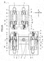
FIG. 2A] FIG. 2A is a plan view of the machine tool inFIG. 1 . - [
FIG. 2B] FIG. 2B is a back view of the machine tool seen from a recess side. - [
FIG. 3] FIG. 3 is a plan view of the machine tool inFIG. 1 , showing a moving direction of each module and a positional relationship between each module and an operator. - [
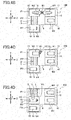
FIG. 4A] FIG. 4A is a schematic view describing processing of a workpiece by the machine tool inFIG. 1 and showing the processing of the workpiece by a fixed module M1. - [
FIG. 4B] FIG. 4B is a schematic view showing the transferring of the workpiece from the fixed module M1 to a movable module M2. - [
FIG. 4C] FIG. 4C is a schematic view showing the processing of the workpiece by the movable module M2. - [
FIG. 4D] FIG. 4D is a schematic view showing the movable module M2 moved to the opposite position of a fixed module M3. - [
FIG. 4E] FIG. 4E is a schematic view showing the transferring of the workpiece from the movable module M2 to the fixed module M3, and the fixed module M1 to which a second workpiece is supplied. - [
FIG. 4F] FIG. 4F is a schematic view showing the processing of the first workpiece by the fixed module M3 and the processing of the second workpiece by the fixed module M1. - [
FIG. 4G] FIG. 4G is a schematic view showing the transferring of the first workpiece from the fixed module M3 to a movable module M4, and the transferring of the second workpiece from the fixed module M1 to the movable module M2. - [
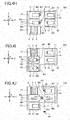
FIG. 4H] FIG. 4H is a schematic view showing the processing of the first workpiece by the movable module M4 and the processing of the second workpiece by the movable module M2. - [
FIG. 4I] FIG. 4I is a schematic view showing the movable module M4 moved to the opposite position of the recess, and the movable module M2 moved to the opposite position of the fixed module M3. - [
FIG. 4J] FIG. 4J is a schematic view showing the processed workpiece carried out from the movable module M4, the transferring of the second workpiece from the movable module M2 to the fixed module M3, and the fixed module M1 to which a third workpiece is supplied. - [
FIG. 5A] FIG. 5A is a plan view briefly showing a machine tool according to another embodiment of the present invention, and showing a closed first isolation wall and a closed second isolation wall. - [
FIG. 5B] FIG. 5B is a plan view showing the open first isolation wall and the open second isolation wall in the machine tool inFIG. 5A . - [
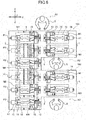
FIG. 6] FIG. 6 is a plan view briefly showing a configuration of a workpiece processing system according to one embodiment of the present invention. - [
FIG. 7] FIG. 7 is a plan view briefly showing a configuration of a workpiece processing system according to another embodiment of the present invention. - [
FIG. 8] FIG. 8 is a plan view briefly showing a configuration of a workpiece processing system according to another embodiment of the present invention. - Hereinafter, an embodiment of a machine tool (automatic lathe) according to the present invention will be described with reference to the drawings. As illustrated in the perspective view of
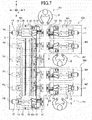
FIG. 1 , the plan view ofFIG. 2A , and the back view ofFIG. 2B , amachine tool 100 of the present embodiment includes abed 1. Four modules M1, M2, M3, and M4 are installed on thebed 1. Hereinafter, an axis line direction of amain spindle 11 of each of the modules M1, M2, M3, and M4 is referred to as a Z-axis direction, a direction orthogonal to the Z-axis direction in the horizontal direction is referred to as a Y-axis direction, and a direction orthogonal to the Z-axis direction and the Y-axis direction is referred to as an X-axis direction. - The two modules M2 and M4 are arranged on the
bed 1 in parallel in the Y-axis direction through a slidingmechanism 2, such that the Z-axis directions of the two modules M2 and M4 are parallel. The slidingmechanism 2 includes aguide rail 3 extending in the Y-axis direction and aball screw 4a. The modules M2 and M4 reciprocate on theguide rail 3 in the Y-axis direction (hereinafter, modules M2 and M4 are referred to as movable modules M2 and M4). The two modules M1 and M3 are arranged on the opposite sides of the movable modules M2 and M4, such that the Z-axis directions of the modules M1 and M3 are parallel in the Y-axis direction. The two modules M1 and M3 are fixed on thebed 1 to be unmovable in the Y-axis direction (hereinafter, modules M1 and M3 are referred to as fixed modules M1 and M3). - As illustrated in
FIG. 2A , thebed 1 includes arecess 8 formed in one corner thereof along the Y-axis and Z-axis directions. Thebed 1 has an approximate L-shape in a planer view. The fixed module M3 is arranged along the outer circumference edge of thebed 1 on therecess 8 side to abut on therecess 8. The fixed module M1 is arranged along the outer circumference edge of thebed 1 on the opposite side of therecess 8 across the fixed module M3. - Each of the modules M1, M2, M3, and M4 has the same basic configuration. A
headstock 12 that supports themain spindle 11 and atool post 13 by which atool 16 for processing a workpiece griped by themain spindle 11 are integrally provided on abase 10. - A known built-in motor (not shown) is provided between the
main spindle 11 and theheadstock 12. Themain spindle 11 rotates about the center of the axis line by the built-in motor. Themain spindle 11 includes in a front end portion (central direction of Z-axis direction of bed 1) thereof a chuck (not shown), and detachably grips the workpiece by the opening and closing operation of the chuck. - Two
guide rails 14 are provided on each of thebases 10 to be parallel in the Y-axis direction. Each of the guide rails 14 extends in the Z-axis direction. Theheadstock 12 is placed on the guide rails 14. Theheadstock 12 is threadably mounted on theball screw 4b provided between the guide rails 14. Theball screw 4b rotates by amotor 17, and theheadstock 12 reciprocates on the guide rails 14 in the Z-axis direction together with the main spindle 11 (refer toFIG. 3 ). - A supporting
base 15 is fixed to the base 10 in front of theheadstock 12. Thetool post 13 is provided in front of the supportingbase 15 to be movable in the X-axis direction and the Y-axis direction. Thetool post 13 moves in the X-axis direction and the Y-axis direction by anX-axis motor 13a and a Y-axis motor 13b. - As illustrated in
FIG. 1 , the supportingbase 15 is formed into a gate shape having anopening 15a. Theheadstock 12 passes through theopening 15a. Theheadstock 12 is disposed to pass through theopening 15a of the supportingbase 15, so that the workpiece griped by themain spindle 11 faces thetool post 13 provided in front of the supportingbase 15. - Each of the modules M1, M2, M3, and M4 holds the workpiece with the
main spindle 11 by the driving control with a controller (not shown), and processes the workpiece into a predetermined shape while selecting thepredetermined tool 16 of thetool post 13 by controlling the rotation of themain spindle 11, the movement of theheadstock 12 in the Z-axis direction, and the movement of thetool post 13 in the X-axis direction and the Y-axis direction. Each of the modules M1, M2, M3, and M4 has a processing region of the workpiece in front of the supporting base 15 (tool post 13 side), and operates as a lathe for processing the workpiece by arranging the end portion of themain spindle 11 in the processing region. Namely, themachine tool 100 includes a plurality of lathes combined as the modules. - As illustrated in
FIGs. 1 to 3 , thebases 10 of the fixed modules M1 and M3 are fixed on thebed 1. The twoguide rails 3 are disposed in parallel in the Z-axis direction, and are provided on thebed 1 to extend from the opposite position of the fixed module M1 to the opposite position of therecess 8. A slidingbody 5 is slidably mounted on theguide rail 3. Thebases 10 of the movable modules M2 and M4 are fixed to the slidingbodies 5, respectively, and are supported on theguide rails 3 to be movable along theguide rail 3. - The
bases 10 of the movable modules M2 and M4 are threadably mounted on the ball screws 4a, respectively, provided between theseparate guide rails 3 throughnuts 10a. Each of theball screws 4a is coaxially disposed, and is connected to each of drivingmotors 6 provided in thebed 1 through abelt 7, as shown inFIGs. 1 and2B . Each of the movable modules M2 and M4 independently reciprocates in the Y-axis direction along theguide rails 3 by rotating each of the drivingmotors 6. - In the
machine tool 100 of the present embodiment, as shown inFIG. 2A , thenut 10a is disposed in the end portion of the bottom surface of thebase 10. As shown inFIG. 3 , when the movable module M4 moves to face therecess 8, the movable module M2 faces both of the fixed modules M1 and M3. In this case, thenut 10a does not abut on the end portion of theball screw 4a. The movable module M2 moves to the positions where the axis line of the main spindle of the movable module M2 is aligned with the axis lines of the main spindles of the fixed modules M1 and M3. When the movable module M2 moves to the position to face the fixed module M1, the movable module M4 faces the fixed module M3, such that the axis line of the main spindle of the movable module M4 is aligned with the axis line of the main spindle of the movable module M3. - By the movement of the movable modules M2 and M4 to the opposite position of the fixed module M1 or the fixed module M3 such that the axis lines of the main spindles of the modules are aligned with each other, and the movement of the
headstocks 12 of the modules in the directions close to each other, the workpiece is transferred between the movable module and the fixed module. - The movable modules M2 and M4 are disposed near the outer circumference edge of the
bed 1 in the Y-axis direction and near the end edge of therecess 8 when the movable modules M2 and M4 move to face the fixed module M1 or the fixed module M3. An operator S therefore positions near the outer circumference edge of thebed 1 on the fixed module M1 side or in therecess 8, so that the operator S and the tool easily reach each part of each module M1, M2, M3, and M4 and the transferring part of the workpiece between the fixed module M1 and M3 and the movable module M2 or the movable module M4. The maintenance operation is thus easily performed. - More specifically, even when four modules are installed on one
bed 1 as themachine tool 100 of the present embodiment, adjustment such as the maintenance of each module and the transferring of the workpiece is easily performed. The freedom of the layout of each module is thus improved, and the machine tool is variously configured. The processing productivity of the workpiece is therefore improved. - In this embodiment, the two fixed modules M1 and M3 are provided as the opposite modules disposed in the opposite sides of the two movable modules M2 and M4 arranged in parallel. However, the present invention is not limited to this configuration. In one example, the fixed module M3 is only provided in the
bed 1 as the opposite module, and the movable modules M2 and M4 are provided to be movable in the Y-axis direction relative to the fixed module M3. With this configuration, when the operator S positions in therecess 8, the operator S and the tool easily reach the transferring part of the workpiece between the fixed module M3 and the movable module M2 or the movable module M4. The operation performance and the maintenance performance are thus improved. - When only one fixed module M3 is provided as the opposite module, the
recess 8 may be provided on both sides of the fixed module M3. With this configuration, when the operator S positions in one of therecesses 8, the operator S adjusts the transferring part of the workpiece between the fixed module M3 and the movable module M2 or the movable module M4 from one of the right and left directions. The operation performance and the maintenance performance are thus improved. After the maintenance, a loader or unloader for the workpiece is disposed in therecess 8. The workpiece is thus easily supplied and carried out. - In this embodiment, the opposite module is fixed on the
bed 1 as the fixed module in an unmovable manner in the Y-axis direction. However, the present invention is not limited to this configuration. The opposite module may be movable in the Y-axis direction by a sliding mechanism to face one of the movable modules. With this configuration, both of the movable modules or both of the opposite modules appropriately move to face each other. The workpiece is thereby transferred and the processing order of the workpiece is freely set, which achieves various processing steps. During the maintenance, each of the modules moves to the position where the adjustment for the maintenance operation and the transferring operation is simplified. The operation performance and the maintenance performance are thus improved. - In the present embodiment, the example in which each of the modules M1, M2, M3, and M4 is a lathe module including a workpiece holder that holds a workpiece, an operation part that performs a predetermined operation to the workpiece held by the workpiece holder, and an operation part holder that holds the operation part. The workpiece holder is the
main spindle 11 that grips the workpiece, the operation part is thetool 16 that processes the workpiece griped by the main spindle, and the operation part holder is thetool post 13 that holds thetool 16. However, the predetermined module may be a processing module for grinding, milling, and gear cutting or a measurement module in which the operation part is a measurement part and a measurement operation is modulated. The predetermined module may be a machine tool that performs complex processing and measurement after processing. - The processing of the workpiece using the
machine tool 100 of the present embodiment will be described with reference toFIGs. 4A to 4J . To simplify the description, the configuration of each of the modules M1, M2, M3 and M4 is simplified and is shown only by thebase 10 and themain spindle 11 in these figures. A plurality of workpieces W1, W2, W3, ... is consequently processed. - In the following description, the workpiece is processed by the fixed module M1, the movable module M2, the fixed module M3, and the movable module M4 in order while being transferred among the modules. However, the present invention is not limited to this order. The workpiece may be processed by the modules in a desired order depending on the processing purpose while being transferred among the modules.
- The workpiece W1 is supplied to the fixed module M1. In this case, the short workpiece W1 is supplied to the
main spindle 11 of the fixed module M1 by a loader (not shown), for example. A bar workpiece may be supplied by a bar feeder (not shown) from the back of the fixed module M1. - As shown in
FIG. 4A , the workpiece W1 is processed by thetool 16, which is selected depending on the processing, in the fixed module M1. - When the fixed module M1 completes the processing of the workpiece W1, the movable module M2 positions in the opposite position P1 of the fixed module M1, and the
main spindle 11 of the fixed module M1 and themain spindle 11 of the movable module M2 move in the directions close to each other to transfer the workpiece W1 (FIG. 4B ). After that, the workpiece W1 is processed by the movable module M2 by which the workpiece W1 is received (FIG. 4C ). - After the processing is completed or during the processing operation of the workpiece W1, the movable module M2 moves to the opposite position P2 of the module M3 from the opposite position P1 (
FIG. 4D ). The movable module M2 performs the processing in the opposite position P2. Next, themain spindle 11 of the movable module M2 and themain spindle 11 of the fixed module M3 move in the directions close to each other to transfer the workpiece W1. While the workpiece W1 is transferred, the second workpiece W2 is supplied to themain spindle 11 of the fixed module M1 (FIG. 4E ). - The workpiece W1 is processed by the fixed module M3 by which the workpiece W1 is received. While the workpiece W1 is processed, the second workpiece W2 is processed by the fixed module M1 (
FIG. 4F ). - When the fixed module M3 completes the processing of the workpiece W1, the movable module M4 moves to the opposite position P2 of the fixed module M3, and the
main spindle 11 of the fixed module M3 and themain spindle 11 of the movable module M4 move in the directions close to each other to transfer the workpiece W1. While the workpiece W1 is transferred, the movable module M2 positions in the opposite position P1 of the fixed module M1, and themain spindle 11 of the fixed module M1 and themain spindle 11 of the movable module M2 move in the directions close to each other to transfer the workpiece W2 (FIG. 4G ). - The workpiece W1 is processed by the movable module M4 by which the workpiece W1 is received. While the workpiece W1 is processed, the workpiece W2 is processed by the movable module M2 by which the workpiece W2 is received (
FIG. 4H ). - After the movable module M4 completes the processing of the workpiece W1 or while the movable module M4 processes the workpiece W1, the movable module M4 moves to the opposite position P3 of the
recess 8 from the opposite position P2. While the movable module M4 moves, the movable module M2 moves to the opposite position P2 of the fixed module M3 from the opposite position P1 after the movable module M2 completes the processing of the workpiece W2 or while the movable module M2 processes the workpiece W2 (FIG. 4I ). In addition, the movable modules M2 and M4 may perform the processing in the opposite positions P2 and P3. - Then, the processed workpiece W1 is carried out from the
main spindle 11 of the movable module M4 in the opposite position P3. While the processed workpiece W1 is carried out, themain spindle 11 of the movable module M2 and themain spindle 11 of the fixed module M3 move in the directions close to each other to transfer the workpiece W2, and a third workpiece W3 is supplied to the fixed module M1 (FIG. 4J ). - After that, similar to the first workpiece W1, the workpiece W2 is processed by the fixed module M3. After the workpiece W2 is transferred to the movable module M4 to be processed, the workpiece W2 is carried out from the movable module M4. The subsequent workpieces after the third workpiece W3 are similarly transferred and the processed.
- As described above, the workpiece is processed while being transferred among the four modules M1, M2, M3, and M4, and a plurality of workpieces is processed in parallel. The modules M1, M2, M3, and M4 are effectively operated to improve the processing productivity.
- Next, another embodiment of the machine tool according to the present invention will be described with reference to
FIGs. 5A and5B . Amachine tool 100A of the present embodiment shown inFIGs. 5A and5B has the basic configuration similar to that of themachine tool 100 of the embodiment shown inFIGs. 1 to 3 . The fixed modules M1 and M3 and the movable modules M2 and M4 are installed on thebed 1 having therecess 8. In this embodiment, as therecess 8 is provided in thebed 1, an operator and a tool easily reaches each part of each module M1, M2, M3, and M4. The maintenance operation is thus easily performed. - In addition to the basic configuration, the
machine tool 100A of this embodiment is provided with afirst isolation wall 20 and asecond isolation wall 21 in an openable and closable manner. Thefirst isolation wall 20 isolates each processing region located on each opposite side (front side) of the fixed module M1 and the movable module M2 and each processing region located on each opposite side (front side) of the fixed module M3 and the movable module M4. Thesecond isolation wall 21 isolates the processing region of the movable module M4 from the processing region of each module M1, M2, and M3. - The
first isolation wall 20 includes a fixedwall 20a which is integrally fixed to the movable module M2 and is provided to project forward from the adjacent movable module M4 side and amovable wall 20b which is provided in the fixed module M1 to be slidable forward and moves back and forth on the adjacent fixed module M3 side. Themovable wall 20b may be slidably moved by hand or may be automatically moved by an appropriate driver. - After the movable module M2 moves to the opposite position of the fixed module M1, the
movable wall 20b slidably moves forward (direction of movable module M2), so that the leading end portion of themovable wall 20b is overlapped with the leading end portion of the fixedwall 20a, as shown inFIG. 5A , and thefirst isolation wall 20 is closed. Each processing region of the fixed module M1 and the movable module M2 is thereby isolated from each processing region of the fixed module M3 and the movable module M4. - The scatter of the cutting fluid and the cutting waste caused by the processing is therefore controlled to the fixed module M3 and the movable module M4 even when the workpiece is processed in each processing region of the movable module M2 and the fixed module M1. It becomes therefore unnecessary to stand by until the completion of the processing. In parallel with this processing, the transferring of the workpiece, the processing of the workpiece, the maintenance of the
main spindle 11, and the carrying out of the workpiece from the movable module M4 are performed on the fixed module M3 and the movable module M4 sides. The operation efficiency is thus improved. - Similarly, the spread of the cutting fluid caused by the processing is controlled to the movable module M2 or the fixed module M1 even when the workpiece is processed by the fixed module M3 or the movable module M4. In parallel with this processing, the workpiece is supplied to the fixed module M1, the workpiece is transferred and processed by the fixed module M1 and the movable module M2, and the maintenance is performed.
- The
first isolation wall 20 opens by slidably moving themovable wall 20b in the direction (backward) opposite to the processing region, as shown inFIG. 5B . The movable module M2 is thereby allowed to move, and the movable module M2 moves to the opposite position of the fixed module M3 after the processing in the fixed module M1 or the movable module M2 is completed. By providing the end portion of the fixedwall 20a in the position which allows the movement of the movable module M2, the movable module M2 moves while processing the workpiece. - When the end portion of the fixed
wall 20a is overlapped with the end portion of themovable wall 20b from the movable module M4 side, the negative effect on the movable module M4 or the fixed module M3 such as the spread of the cutting fluid and the cutting waste caused by the processing of the workpiece by the movable module M2 or the fixed module M1 and the negative effect on the movable module M2 or the fixed module M1 such as the spread of the cutting fluid and the cutting waste caused by the processing of the workpiece by the movable module M4 or the fixed module M3 are controlled on some level during the movement of the movable module M2. - The
second isolation wall 21 includes a fixedwall 21a fixed on thebed 1 and amovable wall 21b provided to be foldable on the movable module M2 side adjacent to the movable module M4. By folding themovable wall 21b, themovable wall 21b is housed on the movable module M4 side, as shown inFIG. 5B , to allow the movement of the movable module M4. Themovable wall 21b is manually or automatically folded. - After the movable module M4 moves to the opposite position of the
recess 8, themovable wall 21b is unfolded, and one end side of themovable wall 21b abuts on the fixedwall 21a. Thesecond isolation wall 21 is thereby closed as shown inFIG. 5A . The movable module M4 is therefore isolated from the processing regions of the other modules M1, M2, and M3. The workpiece is therefore carried out from the movable module M4 and the maintenance is performed in the movable module M4 with no effect of the processing such as the spread of the cutting fluid even while the workpiece is processed by any of the modules M1, M2, and M3. - By closing the
first isolation wall 20 and thesecond isolation wall 21 to isolate the fixed module M1 and the movable module M2, the fixed module M3, and the movable module M4, the workpiece is independently processed and transferred in each processing region, and the maintenance is also independently performed. The operation performance in themachine tool 100A and the freedom degree of the operation are improved. - In the present embodiment, the fixed
wall 21 a is provided on thebed 1. However, the present invention is not limited to this embodiment. The fixedwall 21 a may be provided on the fixed module M3 side. The configuration of the isolation wall of the present invention is not limited to the configurations of thefirst isolation wall 20 and thesecond isolation wall 21. An appropriate configuration may be adopted. - Next, one embodiment of the workpiece processing system according to the present invention using the above-described machine tool will be described with reference to
FIG. 6 . The workpiece processing system of the present embodiment includes twomachine tools recess 8. In each of themachine tools bed 1 provided with therecess 8. In the present embodiment, the workpiece processed by themachine tool 100 disposed on the upstream side of the processing steps is additionally processed by themachine tool 200 disposed on the downstream side. - In the two
machine tools guide rail 3 extending in the Y-axis direction is formed over both of themachine tools machine tools machine tool 100 on the upstream side reciprocates between themachine tool 200 on the downstream side and themachine tool 100 on the upstream side. The movable module M4 includes the function as a processing unit for the workpiece and the function as a supplying unit for the workpiece that carries the workpiece processed by themachine tool 100 on the upstream side to themachine tool 200 on the downstream side to be supplied. - In the workpiece processing system of the present embodiment, the workpiece is processed while being transferred among the modules M1, M2, M3, and M4 of the
machine tool 100 on the upstream side in the above-described steps. When themachine tool 100 completes the processing, the movable module M4 moves to the opposite position P1 of the fixed module M1 of themachine tool 200 on theguide rail 3 in the Y-axis direction while griping the workpiece. - The
main spindle 11 of the movable module M4 and themain spindle 11 of the fixed module M1 of themachine tool 200 move in the directions close to each other to transfer the workpiece between the movable module M4 and the fixed module M1 of themachine tool 200. - After the workpiece is transferred, the movable module M4 moves back to the
machine tool 100 side. On the other hand, in themachine tool 200 by which the workpiece is received, the workpiece is processed by the fixed module M1. Then, the workpiece is carried out after the workpiece is processed while being transferred among the modules M1, M2, M3, and M4 in the steps similar to those of themachine tool 100. One machine tool is configured by the fixed modules M1 and M3 and the movable modules M2 of themachine tool 200, the movable module M4 of themachine tool 100, and therecess 8. - In the present embodiment, the machine tools each including a plurality of modules are arranged in parallel. The workpiece is thus processed in many steps, and a plurality of workpieces is processed in parallel. The processing productivity is therefore improved. In the maintenance, the movable modules M2 and M4 of each
machine tool FIG. 6 ) of thebed 1 on the fixed module M1 side or in the recess 8 (operation regions A2 and A3 ofFIG. 6 ). The operator S and the tool thus easily reach each part of each module M1, M2, M3, and M4 and the transferring part of the workpiece between the fixed modules M1 and M3 and the movable modules M2 and M4, respectively. The adjustment such as the maintenance and the transferring of the workpiece is easily performed. - Next, another embodiment of the workpiece processing system according to the present invention will be described with reference to
FIG. 7 . In the present embodiment, the workpiece processing system includes only two movable modules M2 and M4. The two movable modules M2 and M4 are shared between themachine tools machine tool 100 and the opposite position P2 of the fixed module M3 of themachine tool 200. The movable module M4 reciprocates between the opposite position P2 of the fixed module M3 of themachine tool 100 and the opposite position P3 of therecess 8 of themachine tool 200. - In the workpiece processing system of the present embodiment, for the processing by the
machine tool 100, the movable modules M2 and M4 position on themachine tool 100 side, and the workpiece is processed in the above-described steps while being transferred among the respective modules M1, M2, M3, and M4. - When the
machine tool 100 completes the processing, the movable module M4 moves to the opposite position P1 of themachine tool 200 to transfer the workpiece with the fixed module M1 of themachine tool 200. After that, the movable modules M2 and M4 move on themachine tool 200 side, and operate as the movable modules of themachine tool 200. The workpiece is thereby processed by each of the modules M1, M2, M3, and M4 while being transferred among the modules. After the processing is completed, the movable module M4 moves to the opposite position P3 of therecess 8 to carry out the workpiece. - As described above, in the workpiece processing system of the present embodiment, the machine tools each having a plurality of modules are arranged in parallel. The workpiece is thereby processed in many steps, and the processing performance is improved. The number of movable modules is further reduced to lower the cost and the weight of the workpiece processing system. In the maintenance, the movable modules M2 and M4 move to face the fixed module M1 or the fixed module M3 of the
machine tools bed 1 on the fixed module M1 side of themachine tool 100 or the operation regions A2 and A3 in therecess 8. The adjustment such as the maintenance and the transferring of the workpiece is therefore easily performed. - Next, another embodiment of the workpiece processing system according to the present invention will be described with reference to
FIG. 8 . In the workpiece processing system of the present embodiment, threemachine tools recesses 8. Themachine tools FIG. 8 . - In the workpiece processing system of the present embodiment, when the processing is performed by the
machine tool 100, the movable modules M2-1 and M2-2 position on themachine tool 100 side, and operate as the movable modules of themachine tool 100. The workpiece is processed while being transferred among the modules M-1, M2-1, M3, and M2-2. - Next, when the
machine tool 200 performs the processing, the movable module M2-2 moves from themachine tool 100 to themachine tool 200 side while griping the workpiece, and the workpiece is transferred to the fixed module M1 of themachine tool 200. In this case, the movable module M2-3 moves to themachine tool 200 side, and operates as the movable module of themachine tool 200. The workpiece is processed while being transferred among the modules M1, M2-2, M3, and M2-3. In addition, the module M2-1 on themachine tool 100 side may be used as the movable module on themachine tool 200 side instead of the movable module M2-3. - After that, when the
machine tool 300 performs the processing, the movable module M2-3 or the movable module M2-2 moves from themachine tool 200 to themachine tool 300 side while griping the workpiece to transfer the workpiece to the fixed module M1 of themachine tool 300. After that, when the movable module M2-3 moves to the opposite position P3 of therecess 8, the movable module M2-2 moves from themachine tool 200 side to themachine tool 300 side, and operates as the movable module of themachine tool 300. After the workpiece is processed while being transferred among the modules M1, M2-2, M3, and M2-3, the workpiece is carried out from the movable module M2-3 moved to the opposite position P3. - As described above, in the workpiece processing system of the present embodiment, the machine tools each including a plurality of modules are arranged in parallel. The workpiece is thereby processed in many steps, and the processing productivity is improved. The number of movable modules is reduced to lower the cost and the weight of the workpiece processing system. In the maintenance, the movable modules M2-1, M2-2, and M2-3 move to face the fixed module M1 or the fixed module M3 of any of the
machine tools bed 1 on the fixed module M1 side of themachine tool 100 and the operation regions A2, A3, and A4 in therecess 8. The adjustment such as the maintenance and the transferring of the workpiece is easily performed. - In the workpiece processing system of each embodiment, the
machine tool 100A including the isolation walls as shown inFIGs. 5A and5B may be used. In this case, in the machine tool, by isolating the adjacent modules with the isolation wall, the workpiece is processed in each module, the workpiece is transferred among the modules, and the workpiece is carried out with no negative effect caused by the processing with another module. By isolating the processing regions on the module side in the processing with the isolation wall, the workpiece is transferred among the adjacent machine tools without considering the spread of the cutting fluid even when the workpiece is processed by the module of any of the adjacent machine tools. - Although the embodiments of the present invention have been described above, the present invention is not limited thereto. It should be appreciated that variations may be made in the processing steps using the machine tools according to the processing without departing from the scope of the present invention.
- The present application is based on and claims priority from Japanese Patent Application No.
2014-134634, filed on June 30, 2014
Claims (9)
- A machine tool comprising:a plurality of modules each including a workpiece holder that holds a workpiece and an operation part holder that holds an operation part for performing a predetermined operation to the workpiece held by the workpiece holder, the workpiece holder and the operation part holder being integrally provided; anda bed on which each of the modules is installed, whereinthe modules include two modules arranged in parallel and opposite modules disposed to respectively face the two modules,the workpiece is processed while being transferred among predetermined modules,the modules arranged in parallel are provided as movable modules to be movable in an arrangement direction,a recess is provided next to the opposite side, the recess being formed by cutting out the bed,the movable modules are movable to be aligned with the opposite modules, respectively, andat least one of the movable modules is provided to be movable in an opposite position of the recess.
- The machine tool according to claim 1, wherein
the workpiece holder is a main spindle that grapes the workpiece,
the operation part is a tool that process the workpiece griped by the main spindle, and
the operation part holder is a tool post that holds the tool. - The machine tool according to claim 1 or claim 2, wherein
the opposite modules are unmovably fixed on the bed as fixed modules. - The machine tool according to any one of claims 1 to 3, wherein the opposite modules are two modules arranged in parallel.
- The machine tool according to any one of claims 1 to 4, wherein an isolation wall that isolates processing regions for processing the workpiece is openably and closably provided between adjacent modules to be openable and closable.
- A workpiece processing system comprising a plurality of machine tools according to any one of claims 1 to 5 arranged in parallel through the recess.
- The workpiece processing system according to claim 6, wherein
the movable modules of one of the adjacent machine tools are movably provided in an opposite position of the opposite module of the other of the adjacent machine tools,
the workpiece is transferred between the adjacent machine tools, and
the workpiece is processed in a plurality of steps while being transferred between the machine tools. - The workpiece processing system according to claim 6 or claim 7, wherein one module is commonly used as the movable module of the one of the machine tools and as the movable module of the other of the machine tools.
- The workpiece processing system according to claim 6 or claim 7, wherein two movable modules are commonly used as the movable modules of each of the machine tools arranged in parallel.
Applications Claiming Priority (2)
| Application Number | Priority Date | Filing Date | Title |
|---|---|---|---|
| JP2014134634 | 2014-06-30 | ||
| PCT/JP2015/068063 WO2016002589A1 (en) | 2014-06-30 | 2015-06-23 | Work machine and workpiece machining system |
Publications (3)
| Publication Number | Publication Date |
|---|---|
| EP3162476A1 true EP3162476A1 (en) | 2017-05-03 |
| EP3162476A4 EP3162476A4 (en) | 2018-02-28 |
| EP3162476B1 EP3162476B1 (en) | 2019-10-23 |
Family
ID=55019132
Family Applications (1)
| Application Number | Title | Priority Date | Filing Date |
|---|---|---|---|
| EP15814940.1A Active EP3162476B1 (en) | 2014-06-30 | 2015-06-23 | Machine tool and workpiece processing system |
Country Status (8)
| Country | Link |
|---|---|
| US (1) | US10293409B2 (en) |
| EP (1) | EP3162476B1 (en) |
| JP (1) | JP6480931B2 (en) |
| KR (1) | KR101993067B1 (en) |
| CN (1) | CN106470785B (en) |
| ES (1) | ES2755984T3 (en) |
| TW (1) | TWI659796B (en) |
| WO (1) | WO2016002589A1 (en) |
Cited By (2)
| Publication number | Priority date | Publication date | Assignee | Title |
|---|---|---|---|---|
| WO2020064122A1 (en) | 2018-09-28 | 2020-04-02 | Mikron Sa Agno | Machine base for use in a machining system and machining system comprising such a machine base |
| CN112672838A (en) * | 2018-10-10 | 2021-04-16 | 西铁城时计株式会社 | Machine tool |
Families Citing this family (8)
| Publication number | Priority date | Publication date | Assignee | Title |
|---|---|---|---|---|
| CN106392643A (en) * | 2016-12-05 | 2017-02-15 | 广东中聪机器人科技有限公司 | Four-channel multi-shaft numerically-controlled lathe |
| CN106944883A (en) * | 2017-04-07 | 2017-07-14 | 深圳市华成利工数控设备有限公司 | The many main spindle numerical control processing machines in a kind of pair of gantry |
| CN108933292B (en) | 2017-05-27 | 2020-04-21 | 深圳新宙邦科技股份有限公司 | Lithium-ion battery non-aqueous electrolyte and lithium-ion battery |
| RU184622U1 (en) * | 2018-02-06 | 2018-11-01 | Публичное акционерное общество "Уральский завод тяжелого машиностроения" | UNIT MACHINE |
| JP6481067B1 (en) * | 2018-05-16 | 2019-03-13 | 株式会社滝澤鉄工所 | Machine tool with workpiece transfer mechanism |
| CN109794622B (en) * | 2019-03-18 | 2020-02-14 | 青岛泽瀚机械制造有限公司 | Copper cylinder processing lathe |
| DE102019108415A1 (en) * | 2019-04-01 | 2020-10-01 | Pilz Gmbh & Co. Kg | Method for monitoring the vitality of a number of participants in a distributed technical system |
| CN115139131A (en) * | 2022-05-25 | 2022-10-04 | 江西衡源智能装备股份有限公司 | Full-automatic multi-channel machining machine tool for feeding and discharging |
Family Cites Families (24)
| Publication number | Priority date | Publication date | Assignee | Title |
|---|---|---|---|---|
| US4413539A (en) * | 1979-10-31 | 1983-11-08 | Citizen Watch Company Limited | Numerically controlled lathe |
| CH636543A5 (en) * | 1980-07-16 | 1983-06-15 | Tarex Sa | MACHINE TOOL COMPRISING TWO OPPOSITE COAXIAL SPINDLES. |
| US4612832A (en) * | 1984-04-27 | 1986-09-23 | Kabushiki Kaisha Miyano Tekkosho | Multiple-function machine tool with two spindles |
| US5097575A (en) * | 1987-04-17 | 1992-03-24 | Yamazaki Mazak Corporation | Complex machining machine tool |
| JPH03161202A (en) * | 1989-11-16 | 1991-07-11 | Miyano:Kk | Machine tool |
| US5127140A (en) * | 1989-12-18 | 1992-07-07 | Hitachi Seiki Co., Ltd. | Numerically-controlled lathe, numerically-controlled device therefor and processing procedure thereby |
| JP2767002B2 (en) * | 1990-05-16 | 1998-06-18 | 相生精機株式会社 | Double-sided machining equipment |
| JP2828232B2 (en) * | 1990-06-29 | 1998-11-25 | オ−クマ株式会社 | Opposing spindle lathe |
| US6640678B2 (en) * | 2000-01-18 | 2003-11-04 | Nakamura-Tome Precision Industry Co., Ltd. | Lathe with two-opposed spindles |
| US6637097B2 (en) * | 2000-08-07 | 2003-10-28 | Toshiharu Miyano | System and method for processing elongate workpieces |
| JP4619620B2 (en) * | 2000-09-22 | 2011-01-26 | シチズンホールディングス株式会社 | Automatic lathe |
| JP3878418B2 (en) * | 2001-01-09 | 2007-02-07 | オークマ株式会社 | Machining method and machine tool |
| US6637302B2 (en) * | 2001-03-22 | 2003-10-28 | Toshiharu Tom Miyano | Machining system and method of machining a workpiece using the machining system |
| JP2005125482A (en) * | 2003-10-03 | 2005-05-19 | Tsugami Corp | lathe |
| DE10348459C5 (en) * | 2003-10-14 | 2011-06-09 | Schneider Gmbh & Co. Kg | Apparatus and method for machining lenses |
| JP4789103B2 (en) | 2004-08-06 | 2011-10-12 | セイコーインスツル株式会社 | Production line |
| JP4380756B2 (en) | 2007-10-10 | 2009-12-09 | 株式会社デンソー | Manufacturing equipment |
| JP2010004961A (en) | 2008-06-24 | 2010-01-14 | Kokuyo Co Ltd | Furniture system |
| KR101537135B1 (en) | 2008-07-10 | 2015-07-15 | 시티즌 마쉬나리 가부시키가이샤 | Work processing apparatus and work processing method |
| ITBO20090478A1 (en) | 2009-07-23 | 2011-01-24 | Samp Spa Con Unico Socio | OPERATING MACHINE FOR GEAR PRODUCTION |
| US8371195B2 (en) * | 2009-09-21 | 2013-02-12 | Alex-Tech Machinery Industrial Co., Ltd. | Lathe machine |
| JP2013136137A (en) * | 2011-12-02 | 2013-07-11 | Takeo Kobayashi | Multiple face machining apparatus |
| KR101749289B1 (en) * | 2012-10-26 | 2017-06-20 | 시티즌 도케이 가부시키가이샤 | Machine tool |
| CN103341761B (en) | 2013-07-18 | 2017-12-05 | 南安市瑜鼎投资管理有限公司 | The Automatic Combined machining production line of Double-shaft drilling machine |
-
2015
- 2015-06-23 CN CN201580033473.4A patent/CN106470785B/en active Active
- 2015-06-23 KR KR1020177002536A patent/KR101993067B1/en active Active
- 2015-06-23 JP JP2016531290A patent/JP6480931B2/en active Active
- 2015-06-23 ES ES15814940T patent/ES2755984T3/en active Active
- 2015-06-23 WO PCT/JP2015/068063 patent/WO2016002589A1/en not_active Ceased
- 2015-06-23 US US15/322,676 patent/US10293409B2/en active Active
- 2015-06-23 EP EP15814940.1A patent/EP3162476B1/en active Active
- 2015-06-29 TW TW104120948A patent/TWI659796B/en active
Cited By (6)
| Publication number | Priority date | Publication date | Assignee | Title |
|---|---|---|---|---|
| WO2020064122A1 (en) | 2018-09-28 | 2020-04-02 | Mikron Sa Agno | Machine base for use in a machining system and machining system comprising such a machine base |
| US12350780B2 (en) | 2018-09-28 | 2025-07-08 | Mikron Sa Agno | Machine base for use in a machining system and machining system comprising such a machine base |
| CN112672838A (en) * | 2018-10-10 | 2021-04-16 | 西铁城时计株式会社 | Machine tool |
| US20210346964A1 (en) * | 2018-10-10 | 2021-11-11 | Citizen Watch Co., Ltd. | Machine tool |
| US11919093B2 (en) * | 2018-10-10 | 2024-03-05 | Citizen Watch Co., Ltd. | Machine tool |
| CN112672838B (en) * | 2018-10-10 | 2024-03-26 | 西铁城时计株式会社 | Machine tool |
Also Published As
| Publication number | Publication date |
|---|---|
| US20170136547A1 (en) | 2017-05-18 |
| KR101993067B1 (en) | 2019-06-25 |
| JP6480931B2 (en) | 2019-03-13 |
| CN106470785B (en) | 2019-01-15 |
| US10293409B2 (en) | 2019-05-21 |
| ES2755984T3 (en) | 2020-04-24 |
| TW201618880A (en) | 2016-06-01 |
| CN106470785A (en) | 2017-03-01 |
| EP3162476A4 (en) | 2018-02-28 |
| KR20170021348A (en) | 2017-02-27 |
| WO2016002589A1 (en) | 2016-01-07 |
| TWI659796B (en) | 2019-05-21 |
| EP3162476B1 (en) | 2019-10-23 |
| JPWO2016002589A1 (en) | 2017-04-27 |
Similar Documents
| Publication | Publication Date | Title |
|---|---|---|
| EP3162476B1 (en) | Machine tool and workpiece processing system | |
| US9095954B2 (en) | Apparatus for machining an elongated workpiece | |
| CN103796776B (en) | Lathe | |
| US8082643B2 (en) | Machining apparatus | |
| JP2004160643A (en) | Tool turret and machine tool | |
| JP6199511B1 (en) | Combined processing apparatus and combined processing method | |
| KR20160117617A (en) | Robot cell for the loading and unloading of single-station machine tools during machining | |
| EP2708312A1 (en) | Machining center | |
| US10359765B2 (en) | Control device for machine tool with multi-system programs | |
| JP2008183705A (en) | Workpiece processing device | |
| JP2014065133A (en) | Parallel two-axis composite machine tool | |
| CN102794464B (en) | A double-head CNC lathe | |
| JP6209568B2 (en) | Machine Tools | |
| WO2016027327A1 (en) | Machining center | |
| CN112789139A (en) | Machining system | |
| JP2014065131A (en) | Machine tool system | |
| JPH10138063A (en) | Work machining device | |
| JP5219604B2 (en) | Machine tool pallet changer | |
| JP6876198B2 (en) | Machine Tools | |
| WO2012056837A1 (en) | Machine tool system | |
| JP6964157B2 (en) | Machine tool system | |
| JP2007061937A (en) | Two-spindle three-turret lathe | |
| CN119057485A (en) | Multi-axis multi-channel turning and milling equipment | |
| KR20130077293A (en) | Machine tool having multiple spindle and table | |
| TWM519024U (en) | Multi-axis CNC lathe |
Legal Events
| Date | Code | Title | Description |
|---|---|---|---|
| STAA | Information on the status of an ep patent application or granted ep patent |
Free format text: STATUS: THE INTERNATIONAL PUBLICATION HAS BEEN MADE |
|
| PUAI | Public reference made under article 153(3) epc to a published international application that has entered the european phase |
Free format text: ORIGINAL CODE: 0009012 |
|
| STAA | Information on the status of an ep patent application or granted ep patent |
Free format text: STATUS: REQUEST FOR EXAMINATION WAS MADE |
|
| 17P | Request for examination filed |
Effective date: 20170113 |
|
| AK | Designated contracting states |
Kind code of ref document: A1 Designated state(s): AL AT BE BG CH CY CZ DE DK EE ES FI FR GB GR HR HU IE IS IT LI LT LU LV MC MK MT NL NO PL PT RO RS SE SI SK SM TR |
|
| AX | Request for extension of the european patent |
Extension state: BA ME |
|
| DAV | Request for validation of the european patent (deleted) | ||
| DAX | Request for extension of the european patent (deleted) | ||
| A4 | Supplementary search report drawn up and despatched |
Effective date: 20180126 |
|
| RIC1 | Information provided on ipc code assigned before grant |
Ipc: B23Q 39/02 20060101ALI20180122BHEP Ipc: B23Q 41/04 20060101ALI20180122BHEP Ipc: B23Q 41/02 20060101ALI20180122BHEP Ipc: B23B 3/30 20060101AFI20180122BHEP Ipc: B23Q 37/00 20060101ALI20180122BHEP |
|
| RIC1 | Information provided on ipc code assigned before grant |
Ipc: B23B 3/30 20060101AFI20190214BHEP Ipc: B23Q 39/02 20060101ALI20190214BHEP Ipc: B23Q 37/00 20060101ALI20190214BHEP Ipc: B23Q 41/02 20060101ALI20190214BHEP Ipc: B23Q 41/04 20060101ALI20190214BHEP |
|
| GRAP | Despatch of communication of intention to grant a patent |
Free format text: ORIGINAL CODE: EPIDOSNIGR1 |
|
| STAA | Information on the status of an ep patent application or granted ep patent |
Free format text: STATUS: GRANT OF PATENT IS INTENDED |
|
| INTG | Intention to grant announced |
Effective date: 20190326 |
|
| GRAJ | Information related to disapproval of communication of intention to grant by the applicant or resumption of examination proceedings by the epo deleted |
Free format text: ORIGINAL CODE: EPIDOSDIGR1 |
|
| STAA | Information on the status of an ep patent application or granted ep patent |
Free format text: STATUS: REQUEST FOR EXAMINATION WAS MADE |
|
| INTC | Intention to grant announced (deleted) | ||
| GRAP | Despatch of communication of intention to grant a patent |
Free format text: ORIGINAL CODE: EPIDOSNIGR1 |
|
| STAA | Information on the status of an ep patent application or granted ep patent |
Free format text: STATUS: GRANT OF PATENT IS INTENDED |
|
| INTG | Intention to grant announced |
Effective date: 20190708 |
|
| GRAS | Grant fee paid |
Free format text: ORIGINAL CODE: EPIDOSNIGR3 |
|
| GRAA | (expected) grant |
Free format text: ORIGINAL CODE: 0009210 |
|
| STAA | Information on the status of an ep patent application or granted ep patent |
Free format text: STATUS: THE PATENT HAS BEEN GRANTED |
|
| AK | Designated contracting states |
Kind code of ref document: B1 Designated state(s): AL AT BE BG CH CY CZ DE DK EE ES FI FR GB GR HR HU IE IS IT LI LT LU LV MC MK MT NL NO PL PT RO RS SE SI SK SM TR |
|
| REG | Reference to a national code |
Ref country code: GB Ref legal event code: FG4D |
|
| REG | Reference to a national code |
Ref country code: CH Ref legal event code: EP Ref country code: CH Ref legal event code: NV Representative=s name: BRAUNPAT BRAUN EDER AG, CH |
|
| REG | Reference to a national code |
Ref country code: IE Ref legal event code: FG4D |
|
| REG | Reference to a national code |
Ref country code: DE Ref legal event code: R096 Ref document number: 602015040426 Country of ref document: DE |
|
| REG | Reference to a national code |
Ref country code: AT Ref legal event code: REF Ref document number: 1193123 Country of ref document: AT Kind code of ref document: T Effective date: 20191115 |
|
| REG | Reference to a national code |
Ref country code: NL Ref legal event code: MP Effective date: 20191023 |
|
| REG | Reference to a national code |
Ref country code: LT Ref legal event code: MG4D |
|
| REG | Reference to a national code |
Ref country code: ES Ref legal event code: FG2A Ref document number: 2755984 Country of ref document: ES Kind code of ref document: T3 Effective date: 20200424 |
|
| PG25 | Lapsed in a contracting state [announced via postgrant information from national office to epo] |
Ref country code: LT Free format text: LAPSE BECAUSE OF FAILURE TO SUBMIT A TRANSLATION OF THE DESCRIPTION OR TO PAY THE FEE WITHIN THE PRESCRIBED TIME-LIMIT Effective date: 20191023 Ref country code: NL Free format text: LAPSE BECAUSE OF FAILURE TO SUBMIT A TRANSLATION OF THE DESCRIPTION OR TO PAY THE FEE WITHIN THE PRESCRIBED TIME-LIMIT Effective date: 20191023 Ref country code: SE Free format text: LAPSE BECAUSE OF FAILURE TO SUBMIT A TRANSLATION OF THE DESCRIPTION OR TO PAY THE FEE WITHIN THE PRESCRIBED TIME-LIMIT Effective date: 20191023 Ref country code: LV Free format text: LAPSE BECAUSE OF FAILURE TO SUBMIT A TRANSLATION OF THE DESCRIPTION OR TO PAY THE FEE WITHIN THE PRESCRIBED TIME-LIMIT Effective date: 20191023 Ref country code: GR Free format text: LAPSE BECAUSE OF FAILURE TO SUBMIT A TRANSLATION OF THE DESCRIPTION OR TO PAY THE FEE WITHIN THE PRESCRIBED TIME-LIMIT Effective date: 20200124 Ref country code: NO Free format text: LAPSE BECAUSE OF FAILURE TO SUBMIT A TRANSLATION OF THE DESCRIPTION OR TO PAY THE FEE WITHIN THE PRESCRIBED TIME-LIMIT Effective date: 20200123 Ref country code: PL Free format text: LAPSE BECAUSE OF FAILURE TO SUBMIT A TRANSLATION OF THE DESCRIPTION OR TO PAY THE FEE WITHIN THE PRESCRIBED TIME-LIMIT Effective date: 20191023 Ref country code: BG Free format text: LAPSE BECAUSE OF FAILURE TO SUBMIT A TRANSLATION OF THE DESCRIPTION OR TO PAY THE FEE WITHIN THE PRESCRIBED TIME-LIMIT Effective date: 20200123 Ref country code: FI Free format text: LAPSE BECAUSE OF FAILURE TO SUBMIT A TRANSLATION OF THE DESCRIPTION OR TO PAY THE FEE WITHIN THE PRESCRIBED TIME-LIMIT Effective date: 20191023 Ref country code: PT Free format text: LAPSE BECAUSE OF FAILURE TO SUBMIT A TRANSLATION OF THE DESCRIPTION OR TO PAY THE FEE WITHIN THE PRESCRIBED TIME-LIMIT Effective date: 20200224 |
|
| PG25 | Lapsed in a contracting state [announced via postgrant information from national office to epo] |
Ref country code: RS Free format text: LAPSE BECAUSE OF FAILURE TO SUBMIT A TRANSLATION OF THE DESCRIPTION OR TO PAY THE FEE WITHIN THE PRESCRIBED TIME-LIMIT Effective date: 20191023 Ref country code: IS Free format text: LAPSE BECAUSE OF FAILURE TO SUBMIT A TRANSLATION OF THE DESCRIPTION OR TO PAY THE FEE WITHIN THE PRESCRIBED TIME-LIMIT Effective date: 20200224 Ref country code: HR Free format text: LAPSE BECAUSE OF FAILURE TO SUBMIT A TRANSLATION OF THE DESCRIPTION OR TO PAY THE FEE WITHIN THE PRESCRIBED TIME-LIMIT Effective date: 20191023 |
|
| PG25 | Lapsed in a contracting state [announced via postgrant information from national office to epo] |
Ref country code: AL Free format text: LAPSE BECAUSE OF FAILURE TO SUBMIT A TRANSLATION OF THE DESCRIPTION OR TO PAY THE FEE WITHIN THE PRESCRIBED TIME-LIMIT Effective date: 20191023 |
|
| REG | Reference to a national code |
Ref country code: DE Ref legal event code: R097 Ref document number: 602015040426 Country of ref document: DE |
|
| PG2D | Information on lapse in contracting state deleted |
Ref country code: IS |
|
| PG25 | Lapsed in a contracting state [announced via postgrant information from national office to epo] |
Ref country code: EE Free format text: LAPSE BECAUSE OF FAILURE TO SUBMIT A TRANSLATION OF THE DESCRIPTION OR TO PAY THE FEE WITHIN THE PRESCRIBED TIME-LIMIT Effective date: 20191023 Ref country code: DK Free format text: LAPSE BECAUSE OF FAILURE TO SUBMIT A TRANSLATION OF THE DESCRIPTION OR TO PAY THE FEE WITHIN THE PRESCRIBED TIME-LIMIT Effective date: 20191023 Ref country code: CZ Free format text: LAPSE BECAUSE OF FAILURE TO SUBMIT A TRANSLATION OF THE DESCRIPTION OR TO PAY THE FEE WITHIN THE PRESCRIBED TIME-LIMIT Effective date: 20191023 Ref country code: RO Free format text: LAPSE BECAUSE OF FAILURE TO SUBMIT A TRANSLATION OF THE DESCRIPTION OR TO PAY THE FEE WITHIN THE PRESCRIBED TIME-LIMIT Effective date: 20191023 Ref country code: IS Free format text: LAPSE BECAUSE OF FAILURE TO SUBMIT A TRANSLATION OF THE DESCRIPTION OR TO PAY THE FEE WITHIN THE PRESCRIBED TIME-LIMIT Effective date: 20200223 |
|
| REG | Reference to a national code |
Ref country code: AT Ref legal event code: MK05 Ref document number: 1193123 Country of ref document: AT Kind code of ref document: T Effective date: 20191023 |
|
| PLBE | No opposition filed within time limit |
Free format text: ORIGINAL CODE: 0009261 |
|
| STAA | Information on the status of an ep patent application or granted ep patent |
Free format text: STATUS: NO OPPOSITION FILED WITHIN TIME LIMIT |
|
| PG25 | Lapsed in a contracting state [announced via postgrant information from national office to epo] |
Ref country code: SK Free format text: LAPSE BECAUSE OF FAILURE TO SUBMIT A TRANSLATION OF THE DESCRIPTION OR TO PAY THE FEE WITHIN THE PRESCRIBED TIME-LIMIT Effective date: 20191023 Ref country code: SM Free format text: LAPSE BECAUSE OF FAILURE TO SUBMIT A TRANSLATION OF THE DESCRIPTION OR TO PAY THE FEE WITHIN THE PRESCRIBED TIME-LIMIT Effective date: 20191023 |
|
| 26N | No opposition filed |
Effective date: 20200724 |
|
| PG25 | Lapsed in a contracting state [announced via postgrant information from national office to epo] |
Ref country code: SI Free format text: LAPSE BECAUSE OF FAILURE TO SUBMIT A TRANSLATION OF THE DESCRIPTION OR TO PAY THE FEE WITHIN THE PRESCRIBED TIME-LIMIT Effective date: 20191023 Ref country code: AT Free format text: LAPSE BECAUSE OF FAILURE TO SUBMIT A TRANSLATION OF THE DESCRIPTION OR TO PAY THE FEE WITHIN THE PRESCRIBED TIME-LIMIT Effective date: 20191023 |
|
| PG25 | Lapsed in a contracting state [announced via postgrant information from national office to epo] |
Ref country code: MC Free format text: LAPSE BECAUSE OF FAILURE TO SUBMIT A TRANSLATION OF THE DESCRIPTION OR TO PAY THE FEE WITHIN THE PRESCRIBED TIME-LIMIT Effective date: 20191023 |
|
| GBPC | Gb: european patent ceased through non-payment of renewal fee |
Effective date: 20200623 |
|
| PG25 | Lapsed in a contracting state [announced via postgrant information from national office to epo] |
Ref country code: LU Free format text: LAPSE BECAUSE OF NON-PAYMENT OF DUE FEES Effective date: 20200623 |
|
| REG | Reference to a national code |
Ref country code: BE Ref legal event code: MM Effective date: 20200630 |
|
| PG25 | Lapsed in a contracting state [announced via postgrant information from national office to epo] |
Ref country code: IE Free format text: LAPSE BECAUSE OF NON-PAYMENT OF DUE FEES Effective date: 20200623 Ref country code: GB Free format text: LAPSE BECAUSE OF NON-PAYMENT OF DUE FEES Effective date: 20200623 Ref country code: FR Free format text: LAPSE BECAUSE OF NON-PAYMENT OF DUE FEES Effective date: 20200630 |
|
| PG25 | Lapsed in a contracting state [announced via postgrant information from national office to epo] |
Ref country code: BE Free format text: LAPSE BECAUSE OF NON-PAYMENT OF DUE FEES Effective date: 20200630 |
|
| PG25 | Lapsed in a contracting state [announced via postgrant information from national office to epo] |
Ref country code: TR Free format text: LAPSE BECAUSE OF FAILURE TO SUBMIT A TRANSLATION OF THE DESCRIPTION OR TO PAY THE FEE WITHIN THE PRESCRIBED TIME-LIMIT Effective date: 20191023 Ref country code: MT Free format text: LAPSE BECAUSE OF FAILURE TO SUBMIT A TRANSLATION OF THE DESCRIPTION OR TO PAY THE FEE WITHIN THE PRESCRIBED TIME-LIMIT Effective date: 20191023 Ref country code: CY Free format text: LAPSE BECAUSE OF FAILURE TO SUBMIT A TRANSLATION OF THE DESCRIPTION OR TO PAY THE FEE WITHIN THE PRESCRIBED TIME-LIMIT Effective date: 20191023 |
|
| PG25 | Lapsed in a contracting state [announced via postgrant information from national office to epo] |
Ref country code: MK Free format text: LAPSE BECAUSE OF FAILURE TO SUBMIT A TRANSLATION OF THE DESCRIPTION OR TO PAY THE FEE WITHIN THE PRESCRIBED TIME-LIMIT Effective date: 20191023 |
|
| PGFP | Annual fee paid to national office [announced via postgrant information from national office to epo] |
Ref country code: DE Payment date: 20250429 Year of fee payment: 11 |
|
| PGFP | Annual fee paid to national office [announced via postgrant information from national office to epo] |
Ref country code: IT Payment date: 20250522 Year of fee payment: 11 |
|
| PGFP | Annual fee paid to national office [announced via postgrant information from national office to epo] |
Ref country code: ES Payment date: 20250701 Year of fee payment: 11 |
|
| PGFP | Annual fee paid to national office [announced via postgrant information from national office to epo] |
Ref country code: CH Payment date: 20250701 Year of fee payment: 11 |