EP3162183A1 - Mowing or mulching device - Google Patents
Mowing or mulching device Download PDFInfo
- Publication number
- EP3162183A1 EP3162183A1 EP15192584.9A EP15192584A EP3162183A1 EP 3162183 A1 EP3162183 A1 EP 3162183A1 EP 15192584 A EP15192584 A EP 15192584A EP 3162183 A1 EP3162183 A1 EP 3162183A1
- Authority
- EP
- European Patent Office
- Prior art keywords
- mowing
- vegetation
- mulching device
- cutting tool
- cutting
- Prior art date
- Legal status (The legal status is an assumption and is not a legal conclusion. Google has not performed a legal analysis and makes no representation as to the accuracy of the status listed.)
- Granted
Links
- 239000000758 substrate Substances 0.000 claims abstract description 18
- 239000003337 fertilizer Substances 0.000 claims description 4
- 230000017260 vegetative to reproductive phase transition of meristem Effects 0.000 abstract description 4
- 241000196324 Embryophyta Species 0.000 description 22
- 241000238631 Hexapoda Species 0.000 description 4
- 241000257303 Hymenoptera Species 0.000 description 4
- 241000607479 Yersinia pestis Species 0.000 description 4
- 235000013399 edible fruits Nutrition 0.000 description 3
- 244000025254 Cannabis sativa Species 0.000 description 2
- 206010061217 Infestation Diseases 0.000 description 2
- 239000002362 mulch Substances 0.000 description 2
- 235000015097 nutrients Nutrition 0.000 description 2
- 241000894006 Bacteria Species 0.000 description 1
- 241001465754 Metazoa Species 0.000 description 1
- 241000699670 Mus sp. Species 0.000 description 1
- 241000209504 Poaceae Species 0.000 description 1
- 240000001949 Taraxacum officinale Species 0.000 description 1
- 235000005187 Taraxacum officinale ssp. officinale Nutrition 0.000 description 1
- 241000700605 Viruses Species 0.000 description 1
- 230000001580 bacterial effect Effects 0.000 description 1
- 230000009286 beneficial effect Effects 0.000 description 1
- 230000015572 biosynthetic process Effects 0.000 description 1
- 239000004927 clay Substances 0.000 description 1
- 230000008878 coupling Effects 0.000 description 1
- 238000010168 coupling process Methods 0.000 description 1
- 238000005859 coupling reaction Methods 0.000 description 1
- 230000001419 dependent effect Effects 0.000 description 1
- 238000011161 development Methods 0.000 description 1
- 230000018109 developmental process Effects 0.000 description 1
- 230000007613 environmental effect Effects 0.000 description 1
- 235000021384 green leafy vegetables Nutrition 0.000 description 1
- 239000000575 pesticide Substances 0.000 description 1
- 239000002689 soil Substances 0.000 description 1
- 238000011144 upstream manufacturing Methods 0.000 description 1
Images


Classifications
-
- A—HUMAN NECESSITIES
- A01—AGRICULTURE; FORESTRY; ANIMAL HUSBANDRY; HUNTING; TRAPPING; FISHING
- A01D—HARVESTING; MOWING
- A01D34/00—Mowers; Mowing apparatus of harvesters
- A01D34/01—Mowers; Mowing apparatus of harvesters characterised by features relating to the type of cutting apparatus
- A01D34/412—Mowers; Mowing apparatus of harvesters characterised by features relating to the type of cutting apparatus having rotating cutters
- A01D34/63—Mowers; Mowing apparatus of harvesters characterised by features relating to the type of cutting apparatus having rotating cutters having cutters rotating about a vertical axis
- A01D34/64—Mowers; Mowing apparatus of harvesters characterised by features relating to the type of cutting apparatus having rotating cutters having cutters rotating about a vertical axis mounted on a vehicle, e.g. a tractor, or drawn by an animal or a vehicle
- A01D34/66—Mowers; Mowing apparatus of harvesters characterised by features relating to the type of cutting apparatus having rotating cutters having cutters rotating about a vertical axis mounted on a vehicle, e.g. a tractor, or drawn by an animal or a vehicle with two or more cutters
- A01D34/661—Mounting means
-
- A—HUMAN NECESSITIES
- A01—AGRICULTURE; FORESTRY; ANIMAL HUSBANDRY; HUNTING; TRAPPING; FISHING
- A01D—HARVESTING; MOWING
- A01D34/00—Mowers; Mowing apparatus of harvesters
- A01D34/01—Mowers; Mowing apparatus of harvesters characterised by features relating to the type of cutting apparatus
- A01D34/412—Mowers; Mowing apparatus of harvesters characterised by features relating to the type of cutting apparatus having rotating cutters
- A01D34/63—Mowers; Mowing apparatus of harvesters characterised by features relating to the type of cutting apparatus having rotating cutters having cutters rotating about a vertical axis
- A01D34/74—Cutting-height adjustment
Definitions
- the invention relates to a mowing or mulching device, are cut off by the protruding from a substrate vegetation between two adjacent rows of plants, preferably in a plantation, according to the preamble of claim 1.
- crops or crops are typically grown in rows, so that there is a space between the rows of plants on which grow vegetation, for example blades of grass, dandelions or other greens, which are driven by working machines and at regular intervals
- To mow or mulch intervals are not to unnecessarily feed the nutrients of the substrate in this vegetation but in the growth of neighboring plants, such as fruit trees.
- the flowering vegetation is important from an ecological point of view for the cultivation of high-quality plants, especially fruit trees, to attract bees and other beneficial insects, which pollinate the flowers of the plants or fruit trees better and ecologically to increase the yield.
- a balanced vegetation prevents pest and bacterial infestation of the plants, because such pests are eaten by a variety of different animals and kept small in number.
- a clearance is provided transversely to the direction of movement between two cutting tools, by its width in the traversing state on the ground a separated from the vegetation surface vegetation strip is formed, that on the support frame, a holding rod is fixed, at the free end of a third cutting tool is arranged in the vegetation strip and whose cutting width at least equal to the width of the space between the two outer cutting tools, and that the distance between the third cutting tool and the substrate is variably adjustable by means of the holding linkage, arise at least three vegetation strips associated with the respective cutting tools, in which different high-growing grasses, flowers and the like can grow to form the vegetation area. Also, the so-called consultröpfen the vegetation in the middle vegetation strip is possible to achieve a rapid spread of new flowers.
- the three cutting tools can be brought to an identical level without delay during the driving condition, so that then also creates a uniform high vegetation area.
- a motor drives the cutting tools on the support frame and on the support rod.
- the motor may additionally be coupled to the holding linkage, so that the distance between the third cutting tool and the ground can be variably adjusted by the motor without the need for further drive means.
- the holding linkage is designed as a parallelogram linkage, whose one side is locked to the support frame and the parallel arranged side of the parallelogram linkage is assigned to the third cutting tool, whereby it is achieved that the third cutting tool permanently parallel to the ground is mobile.
- the distance between the third cutting tool and the ground can be adjustable by a pressure piston or linear drive.
- the cutting tools can be designed as sickle mowers or reel mowers whose blades are arranged to rotate horizontally or vertically to the ground.
- the mowing or mulching device can be attached to an agricultural machine.
- the engine may be associated with the agricultural machine but also the mowing or mulching device.
- the cutting tools 8, 9, 13 of the mowing or mulching device 1 are drivingly connected to a motor 6, which is arranged in the agricultural machine 21.
- a telescopic shaft 19 is arranged for transmitting the rotary drive power.
- the telescopic shaft 19 is coupled by means of ball joints 18 kinematically with the support frame 5 and the motor 6 of the agricultural machine 21 and the third cutting tool 13.
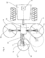
- FIG. 2 Of the FIG. 2 is the mowing or mulching device 1, which can be seen by an agricultural machine 21 between two rows of plants 3 for processing the vegetation in rear view.
- the first cutting mechanism 8 and the second cutting mechanism 9 each form the two outer cutting units 8, 9, which cuts or mulches the vegetation 4 adjacent to the rows of plants 3.
- a vegetation strip 14 is obtained when passing through the vegetation 4 between two rows of plants 3, by means of which, for example, bees or other insects can be attracted to increase the yield.
- FIG. 3a This position is in particular the FIG. 3a to be seen in a side view.
- FIG. 3b the mowing or mulching device 1 can be seen in a further working position with the lowered third cutting tool 13.
- the third cutting tool 13 By delivering the pressure piston 17, the third cutting tool 13 is moved to the parallelogram support rod 11 in the direction of the substrate 2.
- the telescopic shaft 19 and the ball joints 18 compensate for the change in length and angle of the shaft, which is due to a different height position of the third cutting tool 13 to the substrate 2.
- the first and the second cutting tool 8, 9 and the third cutting tool 13 thus cut off the vegetation 4 at a predetermined and identical distance from the substrate 2.
- the vegetation 4 is ordered without the formation of a vegetation strip 14.
- This working position is particularly advantageous for ordering the entire vegetation 4 between two rows of plants 3 and at the ends of the rows of plants 3.
- the mowing and mulching device 1 can therefore also be used for conventional mowing or mulching work.
- the mowing or mulching device can be seen in top view. Accordingly, the first and / or the second cutting tool 8, 9 in the plane parallel and spaced from the ground 2 pivotally to adjust the width of the mower or mulcher to the distance between the two rows of plants 3.
- the three cutting tools 8, 9 and 13 are typically arranged in a plane parallel to the ground 2 in a triangular shape, wherein preferably the third cutting tool 13 in the direction of movement 7 the cutting tools 8, 9 upstream or downstream.
- the cutting tools 8, 9, 13 may be formed as a sickle mower or reel mower. Each cutting tool 8, 9, 13 can be formed from several sickle mowers or Spindelmähern.
- the agricultural working machine 21 can push or pull the mowing or mulching device 1, wherein the direction of movement 7 of the agricultural working machine 21 is freely selectable.
- the mowing or mulching device 1 may be a trailer for an agricultural work machine 21.
- the motor 6 can be assigned to either the agricultural working machine 21 or the mowing or mulching device 1.
- the mowing or mulching device 1 may be an independent vehicle, or a substructure of such.
- the mowing or mulching device 1 may additionally comprise a dosing unit which selectively applies seeds or fertilizer to the vegetation strip 14.
Abstract
Bei einer Mäh- oder Mulchvorrichtung (1), durch die von einem Untergrund (2) abstehende Vegetation (4), die insbesondere zwischen zwei benachbarten Reihen von Pflanzen (3) eine Vegetationsfläche bildet, abzuschneiden sind, bestehend aus: einem in eine Bewegungsrichtung (7) verfahrbaren Traggestell (5), mindestens zwei an dem Traggestell (5) drehbar abgestützten Schneidwerkzeugen (8, 9), die parallel zu dem Untergrund (2) in einer einstellbaren Höhenposition angeordnet sind und durch die die Vegetation (4) jeweils in einer vorgegebene Schnittbreite (10) abgeschnitten ist, und mindestens einen Motor (6), durch den das jeweilige Schneidwerkzeug (8, 9) in Rotation versetzt ist, soll mittig ein Vegetationsstreifen (14) erhalten bleiben und zum anderen die Vegetation (4) an den Stirnseiten der Reihen von Pflanzen (3) ohne einen verbleibenden Vegetationsstreifen (14) zu mähen oder zu mulchen sein. Darüber hinaus soll der Vegetationsstreifen (14) in einer vorgegebenen Höhe, vorzugsweise nach der Blüte mäh- bzw. mulchbar sein. Diese Aufgabe ist dadurch gelöst, dass quer zur Bewegungsrichtung (7) zwischen den einem ersten und einem zweiten Schneidwerkzeug (8, 9) ein Freiraum (12) vorgesehen ist, durch dessen Breite im Verfahrzustand auf dem Untergrund (2) ein von der Vegetationsfläche abgetrennter Vegetationsstreifen (14) entsteht, dass an dem Traggestell (5) ein Haltegestänge (11) befestigt ist, an dessen freien Ende ein drittes Schneidwerkzeug (13) im Bereich des Vegetationsstreifens (14) angeordnet ist und dessen Schnittbreite (10) mindestens der Breite des Freiraumes (12) zwischen den beiden Schneidewerkzeugen (8, 9) entspricht, und dass der Abstand zwischen dem dritten Schneidewerkzeug (13) und dem Untergrund (2) variabel mittels des Haltegestänges (11) einstellbar ist.In a mowing or mulching device (1) through which vegetation (4) protruding from a substrate (2), which forms a vegetation surface in particular between two adjacent rows of plants (3), consists of: one in one direction of movement ( 7) movable support frame (5), at least two on the support frame (5) rotatably supported cutting tools (8, 9) which are arranged parallel to the ground (2) in an adjustable height position and through which the vegetation (4) in each case predetermined cutting width (10) is cut off, and at least one motor (6) through which the respective cutting tool (8, 9) is set in rotation, should be maintained in the middle of a vegetation strip (14) and on the other the vegetation (4) to the End faces of the rows of plants (3) without mowing or mulching a remaining vegetation strip (14). In addition, the vegetation strip (14) should be mowed or mulchable at a predetermined height, preferably after flowering. This object is achieved in that a free space (12) is provided transversely to the direction of movement (7) between the first and a second cutting tool (8, 9), through the width of which in the travel state on the ground (2) a separated from the vegetation surface Vegetation strip (14) is formed, that on the support frame (5) a holding rod (11) is fixed, at the free end of a third cutting tool (13) in the region of the vegetation strip (14) is arranged and its cutting width (10) at least the width of Free space (12) between the two cutting tools (8, 9) corresponds, and that the distance between the third cutting tool (13) and the substrate (2) is adjustable by means of the retaining rod (11).
Description
Die Erfindung bezieht sich auf eine Mäh- oder Mulchvorrichtung, durch die von einem Untergrund abstehende Vegetationen zwischen zwei benachbarten Reihen von Pflanzen, vorzugsweise in einer Plantage, abzuschneiden sind, nach dem Oberbegriff des Patentanspruches 1.The invention relates to a mowing or mulching device, are cut off by the protruding from a substrate vegetation between two adjacent rows of plants, preferably in a plantation, according to the preamble of claim 1.
In der Landwirtschaft werden typischerweise Kultur- oder Nutzpflanzen in Reihen verlaufend angebaut, so dass zwischen den einzelnen Reihen der Pflanzen ein Abstand geschaffen ist, auf den Vegetationen, beispielsweise Grashalme, Löwenzahn oder sonstiges Grünzeug, wachsen, die von Arbeitsmaschinen befahren sind und in regelmäßigen zeitlichen Abständen zu mähen oder zu mulchen sind, um die Nährstoffe des Untergrundes nicht unnötig in diese Vegetation sondern in das Wachstum der benachbarten Pflanzen, beispielsweise Obstbäume, zu leiten.In agriculture, crops or crops are typically grown in rows, so that there is a space between the rows of plants on which grow vegetation, for example blades of grass, dandelions or other greens, which are driven by working machines and at regular intervals To mow or mulch intervals are not to unnecessarily feed the nutrients of the substrate in this vegetation but in the growth of neighboring plants, such as fruit trees.
Zwischen den einzelnen Reihen von Pflanzen ist eine Vegetation angepflanzt, um die Befahrbarkeit des Untergrundes durch die landwirtschaftliche Arbeitsmaschine zu verbessern, so dass keine Lehmfurchen oder sonstige Beschädigungen an dem Boden oder dem Wurzelwerk der Pflanzen beim Überfahren entstehen. Um die Nährstoffkonkurrenz zwischen den Pflanzen und der Vegetation zu verhindern, aber auch den Befall von Schädlingen, beispielsweise Wühlmäusen, rechtzeitig zu erkennen, muss die Vegetation in regelmäßigen Abständen gemäht bzw. gemulcht werden. Derartige Mähgeräte bestehen üblicherweise aus einem oder mehreren parallel zu dem Untergrund rotierenden Schneidmessern, die als Sichelmäher oder Spindelmäher ausgebildet sein können. Derartige Mähgeräte sind auch häufig mit einer Vorrichtung zum Ausbringen von Pflanzenschutzmitteln oder Düngemitteln kombiniert und sind beispielsweise aus der
Es hat sich jedoch als nachteilig herausgestellt, dass sämtliche Vegetation zwischen den Pflanzenreihen abgeschnitten ist und somit auch die blütentreibende Vegetation entfernt ist. Die blütentreibende Vegetation ist jedoch nach ökologischen Gesichtspunkten für den Anbau von hochwertigen Pflanzen, insbesondere von Obstbäumen, wichtig, um Bienen und andere nützliche Insekten anzulocken, durch die die Blüten der Pflanzen oder Obstbäume besser bestäubt werden und um den Ertrag ökologisch zu steigern. Oftmals verhindert nämlich eine ausgewogene Vegetation Ungeziefer- und Bakterienbefall der Pflanzen, denn durch eine Vielzahl von unterschiedlichen Tieren werden solche Schädlinge gefressen und in der Anzahl gering gehalten.However, it has proved to be disadvantageous that all vegetation between the rows of plants is cut off and thus the flowering vegetation is removed. The flowering vegetation, however, is important from an ecological point of view for the cultivation of high-quality plants, especially fruit trees, to attract bees and other beneficial insects, which pollinate the flowers of the plants or fruit trees better and ecologically to increase the yield. Often a balanced vegetation prevents pest and bacterial infestation of the plants, because such pests are eaten by a variety of different animals and kept small in number.
Es ist daher Aufgabe der Erfindung, eine Mäh- bzw. Mulchvorrichtung der eingangs genannten Gattung bereit zu stellen, mittels der zum einen die Vegetation zwischen zwei benachbarten Reihen von Pflanzen mähbar ist, wobei mittig ein Vegetationsstreifen erhalten bleibt und zum anderen die Vegetation an den Stirnseiten der Reihen von Pflanzen ohne einen verbleibenden Vegetationsstreifen zu mähen oder zu mulchen. Darüber hinaus soll der Vegetationsstreifen in einer vorgegebenen Höhe, vorzugsweise nach der Blüte auf dem Vegetationsstreifen, mäh- bzw. mulchbar sein.It is therefore an object of the invention to provide a mowing or mulching device of the type mentioned, by means of which the vegetation between two adjacent rows of plants is mowable, wherein a vegetation strip is preserved in the middle and on the other hand the vegetation on the front sides the rows of plants without mowing or mulching a remaining vegetation strip. In addition, the vegetation strip should be mowed or mulchable at a predetermined height, preferably after flowering on the vegetation strip.
Diese Aufgabe ist erfindungsgemäß durch die Merkmale des kennzeichnenden Teils des Patentanspruches 1 gelöst.This object is achieved by the features of the characterizing part of claim 1.
Weitere vorteilhafte Weiterbildungen der Erfindung ergeben sich aus den Unteransprüchen.Further advantageous developments of the invention will become apparent from the dependent claims.
Dadurch, dass quer zur Bewegungsrichtung zwischen zwei Schneidwerkzeugen ein Freiraum vorgesehen ist, durch dessen Breite im Verfahrzustand auf dem Untergrund ein von der Vegetationsfläche abgetrennter Vegetationsstreifen entsteht, dass an dem Traggestell ein Haltegestänge befestigt ist, an dessen freien Ende ein drittes Schneidwerkzeug im Bereich des Vegetationsstreifens angeordnet ist und dessen Schnittbreite mindestens der Breite des Freiraumes zwischen den beiden äußeren Schneidwerkzeugen entspricht, und dass der Abstand zwischen dem dritten Schneidwerkzeug und dem Untergrund variabel mittels des Haltegestänges einstellbar ist, entstehen mindestens drei den jeweiligen Schneidwerkzeugen zugeordneten Vegetationsstreifen, in denen unterschiedliche hoch wachende Gräser, Blumen und dergleichen zur Bildung der Vegetationsfläche wachsen können. Auch das sogenannte Blütenkröpfen der Vegetation im mittleren Vegetationsstreifen ist möglich, um ein schnelles Ausbreiten von neuen Blüten zu erreichen.Characterized in that a clearance is provided transversely to the direction of movement between two cutting tools, by its width in the traversing state on the ground a separated from the vegetation surface vegetation strip is formed, that on the support frame, a holding rod is fixed, at the free end of a third cutting tool is arranged in the vegetation strip and whose cutting width at least equal to the width of the space between the two outer cutting tools, and that the distance between the third cutting tool and the substrate is variably adjustable by means of the holding linkage, arise at least three vegetation strips associated with the respective cutting tools, in which different high-growing grasses, flowers and the like can grow to form the vegetation area. Also, the so-called Blütenkröpfen the vegetation in the middle vegetation strip is possible to achieve a rapid spread of new flowers.
Die drei Schneidwerkzeuge können ohne zeitliche Verzögerung während des Fahrzustandes auf ein identisches Niveau gebracht sein, so dass dann auch eine einheitliche hohe Vegetationsfläche entsteht.The three cutting tools can be brought to an identical level without delay during the driving condition, so that then also creates a uniform high vegetation area.
Darüber hinaus ist es besonders vorteilhaft, wenn ein Motor die Schneidwerkzeuge an dem Traggestell und an dem Haltegestänge antreibt. Der Motor kann zusätzlich mit dem Haltegestänge gekoppelt sein, so dass durch den Motor der Abstand zwischen dem dritten Schneidwerkzeug und dem Untergrund variabel einstellbar ist, ohne dass weitere Antriebsmittel notwendig sind.Moreover, it is particularly advantageous if a motor drives the cutting tools on the support frame and on the support rod. The motor may additionally be coupled to the holding linkage, so that the distance between the third cutting tool and the ground can be variably adjusted by the motor without the need for further drive means.
Weiterhin vorteilhaft ist, wenn das Haltegestänge als ein Parallelogramm-Gestänge ausgebildet ist, dessen eine Seite an dem Traggestell arretiert ist und die dazu parallel angeordnete Seite des Parallelogramm-Gestänges dem dritten Schneidwerkzeug zugeordnet ist, wodurch erreicht ist, dass das dritte Schneidwerkzeug permanent parallel zu dem Untergrund beweglich ist. Der Abstand zwischen dem dritten Schneidwerkzeug und dem Untergrund kann durch einen Druckkolben oder Linearantrieb einstellbar sein.It is also advantageous if the holding linkage is designed as a parallelogram linkage, whose one side is locked to the support frame and the parallel arranged side of the parallelogram linkage is assigned to the third cutting tool, whereby it is achieved that the third cutting tool permanently parallel to the ground is mobile. The distance between the third cutting tool and the ground can be adjustable by a pressure piston or linear drive.
Die Schneidwerkzeuge können als Sichelmäher oder Spindelmäher ausgebildet sein, deren Messer horizontal oder vertikal zum Untergrund rotierend angeordnet sind.The cutting tools can be designed as sickle mowers or reel mowers whose blades are arranged to rotate horizontally or vertically to the ground.
An dem Traggestell kann vorteilhafterweise eine Dosiervorrichtung angeordnet sein, durch die Samen oder Dünger auf die Vegetation oder den Vegetationsstreifen aufbringbar ist. Dadurch können gezielt auf dem Vegetationsstreifen eine blütentragende Vegetation eingesät werden, wodurch Bienen und andere Insekten verstärk angelockt werden.On the support frame can advantageously be arranged a metering device can be applied by the seeds or fertilizer on the vegetation or the vegetation strip. This allows targeted planting on the vegetation strip flower-bearing vegetation, which attracted bees and other insects amplified.
Die Mäh- bzw. Mulchvorrichtung kann ein Anbaugerät für eine landwirtschaftliche Arbeitsmaschine sein und der Motor der landwirtschaftlichen Arbeitsmaschine kann die Schneidwerkzeuge sowie den Abstand zwischen dem dritten Schneidwerkzeug und dem Untergrund einstellen.The mowing device may be an attachment for an agricultural work machine and the engine of the agricultural work machine may adjust the cutting tools as well as the distance between the third cutting tool and the ground.
Weiterhin vorteilhaft kann die Mäh- bzw. Mulchvorrichtung an eine landwirtschaftliche Arbeitsmaschine anhängbar sein. Der Motor kann der landwirtschaftlichen Arbeitsmaschine aber auch der Mäh- bzw. Mulchvorrichtung zugeordnet sein.Further advantageously, the mowing or mulching device can be attached to an agricultural machine. The engine may be associated with the agricultural machine but also the mowing or mulching device.
In der Zeichnung ist ein erfindungsgemäßes Ausführungsbeispiel dargestellt, das nachfolgend näher erläutert ist. Im Einzelnen zeigt:
- Figur 1
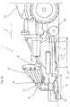
- eine Mäh- bzw. Mulchvorrichtung, die als Anbaugerät an einer landwirtschaftlichen Arbeitsmaschine über einen mit einer Vegetation bewachsenen Untergrund in eine Bewegungsrichtung verfahren ist und aus einem Traggestell mit mehreren Schneidwerkzeugen besteht, an dem ein Haltegestänge mit einem höhenverstellbaren mittleren Schneidwerkzeug fest angeordnet ist, in Seitenansicht,
Figur 2- die Mäh- bzw. Mulchvorrichtung gemäß
Figur 1 , zwischen zwei Reihen von Pflanzen beim Mähen bzw. Mulchen der Vegetation zur Erzeugung eines Vegetationsstreifens, in Ansicht von Hinten, - Figur 3a
- die Mäh- bzw. Mulchvorrichtung gemäß
Figur 1 dessen mittleres Schneidwerkzeug durch das Haltegestänge von dem Untergrund abgehoben gehalten ist, - Figur 3b
- die Mäh- bzw. Mulchvorrichtung gemäß
Figur 3a mit dem abgesenkten mittleren Schneidwerkzeug zum Mähen bzw. Mulchen der gesamten Vegetationsfläche, und Figur 4- die Mäh- bzw. Mulchvorrichtung gemäß
Figur 1 mit einem seitlich verschwenkbaren Schneidwerkzeug zur Vergrößerung der Breite der Mäh- bzw. Mulchvorrichtung.
- FIG. 1
- a mowing or mulching device, which is moved as an attachment to an agricultural machine on a vegetated background in a moving direction and consists of a support frame with a plurality of cutting tools on which a support rod is fixedly mounted with a height-adjustable central cutting tool, in side view .
- FIG. 2
- the mowing or mulching device according to
FIG. 1 , between two rows of plants when mowing or mulching the vegetation to create a vegetation strip, in view from behind, - FIG. 3a
- the mowing or mulching device according to
FIG. 1 whose central cutting tool is held lifted by the support rod from the ground, - FIG. 3b
- the mowing or mulching device according to
FIG. 3a with the lowered central cutting tool for mowing or mulching the entire vegetation area, and - FIG. 4
- the mowing or mulching device according to
FIG. 1 with a laterally pivotable cutting tool for increasing the width of the mowing or mulching device.
Der
Die beiden Schneidwerkzeuge 8 und 9 sind an dem Traggestell 5 abgestützt und bestehen im abgebildeten Ausführungsbeispiel aus mehreren an einer Welle angebrachten Schneidmessern, die im Wesentlichen parallel zu dem Untergrund 2 ausgerichtet sind. Durch die Rotation der Schneidmesser und aufgrund der Relativbewegung zwischen dem jeweiligen Schneidwerkzeug 8, 9 und dem Untergrund 2 entsteht ein abgeschnittener Vegetationsstreifen, dessen Schnittbreite 10 dem Durchmesser des jeweiligen Schneidwerkzeuges 8 bzw. 9 entspricht.The two
Zwischen den beiden äußeren Schneidwerkzeugen 8 und 9, die nämlich voneinander räumlich beabstandet sind, entsteht somit ein Freiraum 12, der von den beiden Schneidwerkzeugen 8 und 9 nicht überfahren ist.Between the two
Da das mittlere Schneidwerkzeug 13 an einem Haltegestänge 11 höhenverstellbar mit dem Traggestell 5 gekoppelt ist, kann dieses in unterschiedliche Positionen abgesenkt oder angehoben werden, so dass der Abstand zwischen dem Schneidwerkzeug 13 und dem Untergrund 2 frei wählbar einstellbar ist. Folglich kann das mittlere Schneidwerkzeug 13 entweder auf einer identischen Höhenposition wie die beiden äußeren Schneidwerkzeuge 8 und 9 oder auf einer unterschiedlichen Höhenposition zu diesen angeordnet sein. Somit entsteht in dem Freiraum 12 ein Vegetationsstreifen 14. In diesen Vegetationsstreifen 14 können Blumensamen ausgebracht werden, durch die entsprechende Blumen hervorsprießen. Die Blüten dieser Blumen in dem Vegetationsstreifen sollen Bienen und weitere nützliche Insekten anlocken, um die Pflanzen 3 zu bestäuben und von schädlichen Umwelteinflüssen, beispielsweise Viren, Bakterien oder Schädlingen, zu entfernen.Since the
Die Schnittbreite 10 des Schneidwerkzeuges 13 ist dabei mindestens derart groß bemessen, dass diese zwischen den beiden Schnittbreiten 10 der äußeren Schneidwerkzeuge 8 und 9 verläuft. Es ist jedoch auch denkbar, dass das mittlere Schneidwerkzeug 13 in die jeweilige Schnittbreite 10 der äußeren Schneidwerkzeuge 8 und 9 eingreift, so dass sich diese teilweise überlappen.The
Die Schneidwerkzeuge 8, 9, 13 der Mäh- bzw. Mulchvorrichtung 1 sind trieblich mit einem Motor 6, der in der landwirtschaftlichen Arbeitsmaschine 21 angeordnet ist, verbunden. Zwischen dem höhenverstellbaren dritten Schneidwerkzeug 13 und dem Traggestell 5 ist zur Übertragung der rotatorischen Antriebsleistung eine Teleskopwelle 19 angeordnet. Die Teleskopwelle 19 ist dabei mittels Kugelgelenken 18 kinematisch mit dem Traggestell 5 bzw. dem Motor 6 der landwirtschaftlichen Arbeitsmaschine 21 und dem dritten Schneidwerkzeug 13 gekoppelt.The
Die triebliche Kopplung der Schneidwerkzeuge 8, 9, 13 mit dem Motor 6 in der Arbeitsmaschine 21 kann über eine Zapfwelle oder pneumatisch, hydraulisch oder elektrisch erfolgen. Auch kann das Haltegestänge 11 bzw. der Druckkolben 17 zur Verstellung des Haltegestänges 11 durch den Motor 6 erfolgen.The drive coupling of the
Der
Das erste Schneidwerk 8 und das zweite Schneidwerk 9 sind quer zur Bewegungsrichtung 7 durch einen Freiraum 12 voneinander beabstandet an dem Traggestell 5 positioniert, so dass die Vegetation 4 in dem Bereich des Freiraums 12 nicht durch die Schneidwerkzeuge 8, 9 bearbeitet ist. In der Bewegungsrichtung 7 nachgelagert ist in dem Bereich des Freiraums 12 das dritte Schneidwerkzeug 13 angeordnet. Durch das Haltegestänge 11 kann der Abstand des dritten Schneidwerkzeuges 13 zu dem Untergrund 2 derart eingestellt werden, dass die blütentreibende Vegetation 4 durch dieses nicht geschnitten ist. Die Schnittbreite 10 des dritten Schneidwerkzeuges 13 ist dabei größer bemessen als die Breite des Freiraumes 12, so dass die Schnittbreite 10 des dritten Schneidwerkzeuges 13 in Bewegungsrichtung 7 mit den Schnittbreite 10 des ersten und des zweiten Schneidwerkzeuges überlappen.The
Bei dieser Arbeitsstellung der Mäh- bzw. Mulchvorrichtung 1 bleibt beim Durchfahren der Vegetation 4 zwischen zwei Reihen von Pflanzen 3 ein Vegetationsstreifen 14 erhalten, durch den beispielsweise Bienen oder andere Insekten zur Steigerung des Ertrages angelockt werden können.In this working position of the mowing or mulching device 1, a
Diese Arbeitsstellung ist insbesondere der
Das erste und das zweite Schneidwerkzeug 8, 9 und das dritte Schneidwerkzeug 13 schneiden somit die Vegetation 4 in einem vorgegebenen und identischen Abstand zu dem Untergrund 2 ab. Bei dieser Einstellung der Mäh- bzw. Mulchvorrichtung 1 ist die Vegetation 4 ohne die Bildung eines Vegetationsstreifens 14 bestellt. Diese Arbeitsstellung ist insbesondere für das Bestellen der gesamten Vegetation 4 zwischen zwei Reihen von Pflanzen 3 und an den Stirnseiten der Reihen von Pflanzen 3 von Vorteil. Die Mäh- und Mulchvorrichtung 1 ist somit auch für herkömmliche Mäh- bzw. Mulcharbeiten einsetzbar.The first and the
Der
Die drei Schneidwerkzeuge 8, 9 und 13 sind typischerweise in einer Ebene parallel zu dem Untergrund 2 in einer dreieckform angeordnet, wobei vorzugsweise das dritte Schneidwerkzeug 13 in der Bewegungsrichtung 7 den Schneidwerkzeugen 8, 9 vor- bzw. nachgelagert ist.The three
Die Schneidwerkzeuge 8, 9, 13 können als Sichelmäher oder Spindelmäher ausgebildet sein. Jedes Schneidwerkzeug 8, 9 ,13 kann dabei aus mehreren Sichelmähern oder Spindelmähern gebildet sein.The
Die landwirtschaftliche Arbeitsmaschine 21 kann die Mäh- bzw. Mulchvorrichtung 1 schieben oder ziehen wobei die Bewegungsrichtung 7 der landwirtschaftlichen Arbeitsmaschine 21 frei wählbar ist. Auch kann die Mäh- bzw. Mulchvorrichtung 1 ein Anhänger für eine landwirtschaftliche Arbeitsmaschine 21 sein. Der Motor 6 kann entweder der landwirtschaftliche Arbeitsmaschine 21 oder der Mäh- bzw. Mulchvorrichtung 1 zugeordnet sein. Auch kann die Mäh- bzw. Mulchvorrichtung 1 ein eigenständiges Fahrzeug, oder einen Unterbau eines solchen sein.The agricultural working
Die Mäh- bzw. Mulchvorrichtung 1 kann zusätzlich eine Dosiereinheit aufweisen, die Samen oder Dünger gezielt auf dem Vegetationsstreifen 14 aufbringt.The mowing or mulching device 1 may additionally comprise a dosing unit which selectively applies seeds or fertilizer to the
Claims (13)
bestehend aus:
dass quer zur Bewegungsrichtung (7) zwischen den einem ersten und einem zweiten Schneidwerkzeug (8, 9) ein Freiraum (12) vorgesehen ist, durch dessen Breite im Verfahrzustand auf dem Untergrund (2) ein von der Vegetationsfläche abgetrennter Vegetationsstreifen (14) entsteht, dass an dem Traggestell (5) ein Haltegestänge (11) befestigt ist, an dessen freien Ende ein drittes Schneidwerkzeug (13) im Bereich des Vegetationsstreifens (14) angeordnet ist und dessen Schnittbreite (10) mindestens der Breite des Freiraumes (12) zwischen den beiden Schneidewerkzeugen (8, 9) entspricht, und dass der Abstand zwischen dem dritten Schneidewerkzeug (13) und dem Untergrund (2) variabel mittels des Haltegestänges (11) einstellbar ist.Mowing or mulching device (1), through which vegetation (4) projecting from a substrate (2), which forms a vegetation area in particular between two adjacent rows of plants (3), is to be cut off,
consisting of:
that transversely to the movement direction (7) between a first and a second cutting tool (8, 9) a free space (12) is provided, by which the width a of the vegetation area severed vegetation strip (14) is produced in Verfahrzustand on the substrate (2), that on the support frame (5) a holding rod (11) is fixed, at the free end of a third Cutting tool (13) in the region of the vegetation strip (14) is arranged and whose cutting width (10) at least the width of the free space (12) between the two cutting tools (8, 9) corresponds, and that the distance between the third cutting tool (13) and the background (2) is variably adjustable by means of the retaining rod (11).
dadurch gekennzeichnet,
dass ein Motor (6) die Schneidwerkzeuge (8, 9, 13) an dem Traggestell (5) und an dem Haltegestänge (11) antreibt.Mowing or mulching device (1) according to claim 1
characterized,
that a motor (6), the cutting tools (8, 9, 13) on the support frame (5) and on the retaining rod (11) drives.
dadurch gekennzeichnet,
dass durch den Motor (6) den Abstand zwischen dem dritten Schneidewerkzeug (13) und dem Untergrund (2) variabel einstellbar istMowing or mulching device (1) according to claim 1 or 2
characterized,
in that the distance between the third cutting tool (13) and the substrate (2) can be variably adjusted by the motor (6)
dadurch gekennzeichnet,
dass das Haltegestänge (11) als einem Parallelogramm-Gestänge (11) ausgebildet ist, dass eine Seite des Parallelogramm-Gestänges (11) dem Traggestell (5) fest zugeordnet ist und die dazu parallel angeordnete Seite des Parallelogramm-Gestänges (11) dem dritten Schneidwerkzeug (13) zugeordnet ist.Mowing or mulching device (1) according to claim 1, 2 or 3
characterized,
in that the holding linkage (11) is designed as a parallelogram linkage (11), that one side of the parallelogram linkage (11) is fixedly assigned to the supporting frame (5) and the side of the parallelogram linkage (11) arranged parallel thereto is assigned to the third Associated with cutting tool (13).
dadurch gekennzeichnet,
dass der Abstand zwischen dem dritten Schneidewerkzeug (13) und dem Untergrund (2) durch einen Druckkolben (17) oder Linearantrieb einstellbar ist.Mowing or mulching device (1) according to one of claims 1 to 4
characterized,
that the distance between the third cutting tool (13) and the base (2) by a plunger (17) or linear drive is adjustable.
dadurch gekennzeichnet,
dass das dritte Schneidwerkzeug (13) an dem Haltegestänge (11) mit dem Motor (6) mittels Kugelgelenken (18) und einer Teleskopwelle (19) gekoppelt ist.Mowing or mulching device (1) according to one of claims 1 to 5
characterized,
in that the third cutting tool (13) on the holding rod (11) is coupled to the motor (6) by means of ball joints (18) and a telescopic shaft (19).
dass die Schneidwerkzeuge (8, 9, 13) als Sichelmäher oder Spindelmäher ausgebildet sind.Mowing or mulching device (1) according to one of claims 1 to 6
the cutting tools (8, 9, 13) are designed as sickle mowers or reel mowers.
dass an dem Traggestell (5) eine Dosiervorrichtung angeordnet ist und dass durch die Dosiervorrichtung Samen oder Dünger auf die Vegetation (4) und/oder dem Vegetationsstreifen (14) aufbringbar ist.Mowing or mulching device (1) according to one of claims 1 to 6
in that a metering device is arranged on the support frame (5) and that seeds or fertilizer can be applied to the vegetation (4) and / or the vegetation strip (14) by the metering device.
dadurch gekennzeichnet,
dass das Mäh- bzw. Mulchvorrichtung (1) ein Anbaugerät für eine landwirtschaftlichen Arbeitsmaschine (21) ist, und dass der Motor (6) der landwirtschaftlichen Arbeitsmaschine (21) zugeordnet ist.Mowing or mulching device (1) according to one of claims 1 to 6
characterized,
in that the mowing or mulching device (1) is an attachment for an agricultural implement (21) and that the motor (6) is associated with the agricultural implement (21).
dadurch gekennzeichnet,
dass der Abstand zwischen dem Untergrund (2) und der Mäh- bzw. Mulchvorrichtung (1) durch die Arbeitsmaschine (21) einstellbar istMowing or mulching device (1) according to claim 7
characterized,
that the distance between the base (2) and the mowing and mulching device (1) through the work machine (21) is adjustable
dadurch gekennzeichnet,
dass das Mäh- bzw. Mulchvorrichtung (1) an eine landwirtschaftlichen Arbeitsmaschine (21) anhängbar ist.Mowing or mulching device (1) according to one of claims 1 to 6
characterized,
that the mowing and mulching device (1) is appendable to an agricultural working machine (21).
dadurch gekennzeichnet,
dass das Mäh- bzw. Mulchvorrichtung (1) ein eigenständiges Fahrzeug ist.Mowing or mulching device (1) according to one of claims 1 to 6
characterized,
that the mowing and mulching device (1) is an autonomous vehicle.
dadurch gekennzeichnet,
dass das mittlere Schneidewerkzeug (13) in Bewegungsrichtung in einer Ebene parallel und beabstandet zu den Schneidwerkzeugen (8, 9) die an dem Traggestell (5) abgestützten angeordnet sind.Mowing or mulching device (1) according to claim 1,
characterized,
that the central cutter (13) in the direction of movement in a plane parallel to and spaced from the cutting tools (8, 9) fixed to the supporting frame (5) are arranged supported.
Priority Applications (2)
| Application Number | Priority Date | Filing Date | Title |
|---|---|---|---|
| PL15192584T PL3162183T3 (en) | 2015-11-02 | 2015-11-02 | Mowing or mulching device |
| EP15192584.9A EP3162183B1 (en) | 2015-11-02 | 2015-11-02 | Mowing or mulching device |
Applications Claiming Priority (1)
| Application Number | Priority Date | Filing Date | Title |
|---|---|---|---|
| EP15192584.9A EP3162183B1 (en) | 2015-11-02 | 2015-11-02 | Mowing or mulching device |
Publications (2)
| Publication Number | Publication Date |
|---|---|
| EP3162183A1 true EP3162183A1 (en) | 2017-05-03 |
| EP3162183B1 EP3162183B1 (en) | 2021-08-18 |
Family
ID=54366049
Family Applications (1)
| Application Number | Title | Priority Date | Filing Date |
|---|---|---|---|
| EP15192584.9A Active EP3162183B1 (en) | 2015-11-02 | 2015-11-02 | Mowing or mulching device |
Country Status (2)
| Country | Link |
|---|---|
| EP (1) | EP3162183B1 (en) |
| PL (1) | PL3162183T3 (en) |
Cited By (6)
| Publication number | Priority date | Publication date | Assignee | Title |
|---|---|---|---|---|
| EP3469865A1 (en) * | 2017-10-13 | 2019-04-17 | Fischer Maschinenbau GmbH & Co. KG | Mulching device with hammer and sickle mower |
| WO2020161001A1 (en) * | 2019-02-04 | 2020-08-13 | Kverneland Group Kerteminde As | A mower for an agricultural machine |
| CN112970432A (en) * | 2019-12-13 | 2021-06-18 | 苏州宝时得电动工具有限公司 | Self-moving gardening equipment |
| EP3878263A1 (en) * | 2020-03-11 | 2021-09-15 | AGCO International GmbH | Agricultural apparatus |
| CN113455180A (en) * | 2021-06-25 | 2021-10-01 | 山东省农业机械科学研究院 | Circular cutting harvesting device with auxiliary advancing operation function |
| EP3909413A1 (en) | 2020-05-14 | 2021-11-17 | Maschinenfabrik Bermatingen GmbH & Co. KG | Mowing or mulching device and cutting tool for same |
Citations (6)
| Publication number | Priority date | Publication date | Assignee | Title |
|---|---|---|---|---|
| DE4409113C1 (en) * | 1994-03-17 | 1995-09-07 | Fortschritt Erntemaschinen | Steered work unit combination on front-steered support vehicle |
| DE20108583U1 (en) | 2000-05-19 | 2001-09-20 | Riegger Lorenz | Tool for plant growing |
| EP1405556A2 (en) * | 2002-10-06 | 2004-04-07 | Claas Saulgau Gmbh | Automotive mower with large working-width |
| US20100115905A1 (en) | 2008-02-07 | 2010-05-13 | Degelman Industries Ltd. | Liquid herbicide applicator |
| WO2011136666A2 (en) * | 2010-04-29 | 2011-11-03 | Trimax Mowing Systems Nz Limited | Drive system for lateral deck mowers |
| US8166735B1 (en) * | 2002-11-13 | 2012-05-01 | Wing Product Development Corp. | Pull type gang mower |
-
2015
- 2015-11-02 EP EP15192584.9A patent/EP3162183B1/en active Active
- 2015-11-02 PL PL15192584T patent/PL3162183T3/en unknown
Patent Citations (6)
| Publication number | Priority date | Publication date | Assignee | Title |
|---|---|---|---|---|
| DE4409113C1 (en) * | 1994-03-17 | 1995-09-07 | Fortschritt Erntemaschinen | Steered work unit combination on front-steered support vehicle |
| DE20108583U1 (en) | 2000-05-19 | 2001-09-20 | Riegger Lorenz | Tool for plant growing |
| EP1405556A2 (en) * | 2002-10-06 | 2004-04-07 | Claas Saulgau Gmbh | Automotive mower with large working-width |
| US8166735B1 (en) * | 2002-11-13 | 2012-05-01 | Wing Product Development Corp. | Pull type gang mower |
| US20100115905A1 (en) | 2008-02-07 | 2010-05-13 | Degelman Industries Ltd. | Liquid herbicide applicator |
| WO2011136666A2 (en) * | 2010-04-29 | 2011-11-03 | Trimax Mowing Systems Nz Limited | Drive system for lateral deck mowers |
Cited By (8)
| Publication number | Priority date | Publication date | Assignee | Title |
|---|---|---|---|---|
| EP3469865A1 (en) * | 2017-10-13 | 2019-04-17 | Fischer Maschinenbau GmbH & Co. KG | Mulching device with hammer and sickle mower |
| DE102017123850A1 (en) | 2017-10-13 | 2019-04-18 | Fischer Maschinenbau GmbH & Co. KG | Mulcher with flail and sickle mower |
| WO2020161001A1 (en) * | 2019-02-04 | 2020-08-13 | Kverneland Group Kerteminde As | A mower for an agricultural machine |
| CN112970432A (en) * | 2019-12-13 | 2021-06-18 | 苏州宝时得电动工具有限公司 | Self-moving gardening equipment |
| CN112970432B (en) * | 2019-12-13 | 2024-02-20 | 苏州宝时得电动工具有限公司 | Self-moving gardening equipment |
| EP3878263A1 (en) * | 2020-03-11 | 2021-09-15 | AGCO International GmbH | Agricultural apparatus |
| EP3909413A1 (en) | 2020-05-14 | 2021-11-17 | Maschinenfabrik Bermatingen GmbH & Co. KG | Mowing or mulching device and cutting tool for same |
| CN113455180A (en) * | 2021-06-25 | 2021-10-01 | 山东省农业机械科学研究院 | Circular cutting harvesting device with auxiliary advancing operation function |
Also Published As
| Publication number | Publication date |
|---|---|
| PL3162183T3 (en) | 2022-01-10 |
| EP3162183B1 (en) | 2021-08-18 |
Similar Documents
| Publication | Publication Date | Title |
|---|---|---|
| EP3162183B1 (en) | Mowing or mulching device | |
| DE832514C (en) | Process and tillage machine for growing crops | |
| EP0049330B1 (en) | Method of sowing seeds, preparing a seed bed, and tool-combination suitable for carrying out the method | |
| CH630226A5 (en) | Method and apparatus for making sowing or planting rows in fields | |
| EP3387890A1 (en) | Series unit for mechanical weed control, agricultural machine with at least two such series units and method for mechanical weed control | |
| EP3804484A1 (en) | Device for caring for grapes and plants laid out in rows and machine for operating same | |
| EP0407896B1 (en) | Groundworking machine for row cultures | |
| DE1457690A1 (en) | Garden and arable equipment | |
| DE3830141C1 (en) | Method and apparatus for working the growth between the rows of young standing maize plants in maize-cultivation areas | |
| EP0025568A1 (en) | Method and implement for soil loosening | |
| EP0193804B1 (en) | Method for sowing agricultural crops | |
| EP2882274B1 (en) | Device for cutting a blanket of organic material lying on the ground and use thereof | |
| DE4022156A1 (en) | Agricultural attachment for tractor - has number of separate cutters and skimmers with holes fixed at intervals along transverse frame | |
| DE102012107068A1 (en) | Harvesting device for harvesting corn | |
| DE4110137C1 (en) | ||
| DE102010051170A1 (en) | Three-phase plow i.e. soil tilling device, for use with e.g. mulcher, has rail pushing back turned soil to lateral edges of furrow trough, and plow units arranged in parallel or moved in direction without influencing overall length of plow | |
| WO2020079117A1 (en) | Device and method for mechanical weed control | |
| DE2146696A1 (en) | Intensive agricultural cultivation method and apparatus | |
| EP2394504A1 (en) | Device for pulling a spray truck, preferably a tractor | |
| US2675645A (en) | Method of agricultural cultivation | |
| DE2436308A1 (en) | Machine picking, chopping and distributing surplus straw and weeds - has horizontal-axled rotary mover-cylinder in housing | |
| DE845724C (en) | Soil tillage device with a drive wheel | |
| EP0396182B1 (en) | Hoeing or weeding machine for agriculture and horticulture | |
| EP3967123A1 (en) | Device and method of processing ground vegetation | |
| DE3420123A1 (en) | Working method for the harvesting of field crops, for the optimum utilisation of crop residues along with simultaneous soil-working, for seedbed preparation and for soil covering |
Legal Events
| Date | Code | Title | Description |
|---|---|---|---|
| PUAI | Public reference made under article 153(3) epc to a published international application that has entered the european phase |
Free format text: ORIGINAL CODE: 0009012 |
|
| STAA | Information on the status of an ep patent application or granted ep patent |
Free format text: STATUS: THE APPLICATION HAS BEEN PUBLISHED |
|
| AK | Designated contracting states |
Kind code of ref document: A1 Designated state(s): AL AT BE BG CH CY CZ DE DK EE ES FI FR GB GR HR HU IE IS IT LI LT LU LV MC MK MT NL NO PL PT RO RS SE SI SK SM TR |
|
| AX | Request for extension of the european patent |
Extension state: BA ME |
|
| STAA | Information on the status of an ep patent application or granted ep patent |
Free format text: STATUS: REQUEST FOR EXAMINATION WAS MADE |
|
| 17P | Request for examination filed |
Effective date: 20171024 |
|
| RBV | Designated contracting states (corrected) |
Designated state(s): AL AT BE BG CH CY CZ DE DK EE ES FI FR GB GR HR HU IE IS IT LI LT LU LV MC MK MT NL NO PL PT RO RS SE SI SK SM TR |
|
| STAA | Information on the status of an ep patent application or granted ep patent |
Free format text: STATUS: EXAMINATION IS IN PROGRESS |
|
| 17Q | First examination report despatched |
Effective date: 20200213 |
|
| STAA | Information on the status of an ep patent application or granted ep patent |
Free format text: STATUS: EXAMINATION IS IN PROGRESS |
|
| GRAP | Despatch of communication of intention to grant a patent |
Free format text: ORIGINAL CODE: EPIDOSNIGR1 |
|
| STAA | Information on the status of an ep patent application or granted ep patent |
Free format text: STATUS: GRANT OF PATENT IS INTENDED |
|
| INTG | Intention to grant announced |
Effective date: 20210331 |
|
| GRAS | Grant fee paid |
Free format text: ORIGINAL CODE: EPIDOSNIGR3 |
|
| GRAA | (expected) grant |
Free format text: ORIGINAL CODE: 0009210 |
|
| STAA | Information on the status of an ep patent application or granted ep patent |
Free format text: STATUS: THE PATENT HAS BEEN GRANTED |
|
| AK | Designated contracting states |
Kind code of ref document: B1 Designated state(s): AL AT BE BG CH CY CZ DE DK EE ES FI FR GB GR HR HU IE IS IT LI LT LU LV MC MK MT NL NO PL PT RO RS SE SI SK SM TR |
|
| REG | Reference to a national code |
Ref country code: GB Ref legal event code: FG4D Free format text: NOT ENGLISH |
|
| REG | Reference to a national code |
Ref country code: CH Ref legal event code: EP |
|
| REG | Reference to a national code |
Ref country code: DE Ref legal event code: R096 Ref document number: 502015015064 Country of ref document: DE |
|
| REG | Reference to a national code |
Ref country code: IE Ref legal event code: FG4D Free format text: LANGUAGE OF EP DOCUMENT: GERMAN Ref country code: AT Ref legal event code: REF Ref document number: 1420776 Country of ref document: AT Kind code of ref document: T Effective date: 20210915 |
|
| REG | Reference to a national code |
Ref country code: LT Ref legal event code: MG9D |
|
| REG | Reference to a national code |
Ref country code: NL Ref legal event code: MP Effective date: 20210818 |
|
| PG25 | Lapsed in a contracting state [announced via postgrant information from national office to epo] |
Ref country code: RS Free format text: LAPSE BECAUSE OF FAILURE TO SUBMIT A TRANSLATION OF THE DESCRIPTION OR TO PAY THE FEE WITHIN THE PRESCRIBED TIME-LIMIT Effective date: 20210818 Ref country code: SE Free format text: LAPSE BECAUSE OF FAILURE TO SUBMIT A TRANSLATION OF THE DESCRIPTION OR TO PAY THE FEE WITHIN THE PRESCRIBED TIME-LIMIT Effective date: 20210818 Ref country code: HR Free format text: LAPSE BECAUSE OF FAILURE TO SUBMIT A TRANSLATION OF THE DESCRIPTION OR TO PAY THE FEE WITHIN THE PRESCRIBED TIME-LIMIT Effective date: 20210818 Ref country code: LT Free format text: LAPSE BECAUSE OF FAILURE TO SUBMIT A TRANSLATION OF THE DESCRIPTION OR TO PAY THE FEE WITHIN THE PRESCRIBED TIME-LIMIT Effective date: 20210818 Ref country code: BG Free format text: LAPSE BECAUSE OF FAILURE TO SUBMIT A TRANSLATION OF THE DESCRIPTION OR TO PAY THE FEE WITHIN THE PRESCRIBED TIME-LIMIT Effective date: 20211118 Ref country code: NO Free format text: LAPSE BECAUSE OF FAILURE TO SUBMIT A TRANSLATION OF THE DESCRIPTION OR TO PAY THE FEE WITHIN THE PRESCRIBED TIME-LIMIT Effective date: 20211118 Ref country code: PT Free format text: LAPSE BECAUSE OF FAILURE TO SUBMIT A TRANSLATION OF THE DESCRIPTION OR TO PAY THE FEE WITHIN THE PRESCRIBED TIME-LIMIT Effective date: 20211220 Ref country code: FI Free format text: LAPSE BECAUSE OF FAILURE TO SUBMIT A TRANSLATION OF THE DESCRIPTION OR TO PAY THE FEE WITHIN THE PRESCRIBED TIME-LIMIT Effective date: 20210818 Ref country code: ES Free format text: LAPSE BECAUSE OF FAILURE TO SUBMIT A TRANSLATION OF THE DESCRIPTION OR TO PAY THE FEE WITHIN THE PRESCRIBED TIME-LIMIT Effective date: 20210818 |
|
| PG25 | Lapsed in a contracting state [announced via postgrant information from national office to epo] |
Ref country code: LV Free format text: LAPSE BECAUSE OF FAILURE TO SUBMIT A TRANSLATION OF THE DESCRIPTION OR TO PAY THE FEE WITHIN THE PRESCRIBED TIME-LIMIT Effective date: 20210818 Ref country code: GR Free format text: LAPSE BECAUSE OF FAILURE TO SUBMIT A TRANSLATION OF THE DESCRIPTION OR TO PAY THE FEE WITHIN THE PRESCRIBED TIME-LIMIT Effective date: 20211119 |
|
| PG25 | Lapsed in a contracting state [announced via postgrant information from national office to epo] |
Ref country code: NL Free format text: LAPSE BECAUSE OF FAILURE TO SUBMIT A TRANSLATION OF THE DESCRIPTION OR TO PAY THE FEE WITHIN THE PRESCRIBED TIME-LIMIT Effective date: 20210818 |
|
| REG | Reference to a national code |
Ref country code: DE Ref legal event code: R082 Ref document number: 502015015064 Country of ref document: DE Representative=s name: GEITZ PATENTANWAELTE PARTG MBB, DE Ref country code: DE Ref legal event code: R082 Ref document number: 502015015064 Country of ref document: DE Representative=s name: GEITZ TRUCKENMUELLER LUCHT CHRIST PATENTANWAEL, DE |
|
| PG25 | Lapsed in a contracting state [announced via postgrant information from national office to epo] |
Ref country code: DK Free format text: LAPSE BECAUSE OF FAILURE TO SUBMIT A TRANSLATION OF THE DESCRIPTION OR TO PAY THE FEE WITHIN THE PRESCRIBED TIME-LIMIT Effective date: 20210818 |
|
| REG | Reference to a national code |
Ref country code: DE Ref legal event code: R097 Ref document number: 502015015064 Country of ref document: DE |
|
| PG25 | Lapsed in a contracting state [announced via postgrant information from national office to epo] |
Ref country code: SM Free format text: LAPSE BECAUSE OF FAILURE TO SUBMIT A TRANSLATION OF THE DESCRIPTION OR TO PAY THE FEE WITHIN THE PRESCRIBED TIME-LIMIT Effective date: 20210818 Ref country code: SK Free format text: LAPSE BECAUSE OF FAILURE TO SUBMIT A TRANSLATION OF THE DESCRIPTION OR TO PAY THE FEE WITHIN THE PRESCRIBED TIME-LIMIT Effective date: 20210818 Ref country code: RO Free format text: LAPSE BECAUSE OF FAILURE TO SUBMIT A TRANSLATION OF THE DESCRIPTION OR TO PAY THE FEE WITHIN THE PRESCRIBED TIME-LIMIT Effective date: 20210818 Ref country code: EE Free format text: LAPSE BECAUSE OF FAILURE TO SUBMIT A TRANSLATION OF THE DESCRIPTION OR TO PAY THE FEE WITHIN THE PRESCRIBED TIME-LIMIT Effective date: 20210818 Ref country code: CZ Free format text: LAPSE BECAUSE OF FAILURE TO SUBMIT A TRANSLATION OF THE DESCRIPTION OR TO PAY THE FEE WITHIN THE PRESCRIBED TIME-LIMIT Effective date: 20210818 Ref country code: AL Free format text: LAPSE BECAUSE OF FAILURE TO SUBMIT A TRANSLATION OF THE DESCRIPTION OR TO PAY THE FEE WITHIN THE PRESCRIBED TIME-LIMIT Effective date: 20210818 |
|
| PLBE | No opposition filed within time limit |
Free format text: ORIGINAL CODE: 0009261 |
|
| STAA | Information on the status of an ep patent application or granted ep patent |
Free format text: STATUS: NO OPPOSITION FILED WITHIN TIME LIMIT |
|
| PG25 | Lapsed in a contracting state [announced via postgrant information from national office to epo] |
Ref country code: MC Free format text: LAPSE BECAUSE OF FAILURE TO SUBMIT A TRANSLATION OF THE DESCRIPTION OR TO PAY THE FEE WITHIN THE PRESCRIBED TIME-LIMIT Effective date: 20210818 |
|
| 26N | No opposition filed |
Effective date: 20220519 |
|
| GBPC | Gb: european patent ceased through non-payment of renewal fee |
Effective date: 20211118 |
|
| PG25 | Lapsed in a contracting state [announced via postgrant information from national office to epo] |
Ref country code: LU Free format text: LAPSE BECAUSE OF NON-PAYMENT OF DUE FEES Effective date: 20211102 Ref country code: BE Free format text: LAPSE BECAUSE OF NON-PAYMENT OF DUE FEES Effective date: 20211130 |
|
| REG | Reference to a national code |
Ref country code: BE Ref legal event code: MM Effective date: 20211130 |
|
| PG25 | Lapsed in a contracting state [announced via postgrant information from national office to epo] |
Ref country code: SI Free format text: LAPSE BECAUSE OF FAILURE TO SUBMIT A TRANSLATION OF THE DESCRIPTION OR TO PAY THE FEE WITHIN THE PRESCRIBED TIME-LIMIT Effective date: 20210818 |
|
| PG25 | Lapsed in a contracting state [announced via postgrant information from national office to epo] |
Ref country code: IE Free format text: LAPSE BECAUSE OF NON-PAYMENT OF DUE FEES Effective date: 20211102 Ref country code: GB Free format text: LAPSE BECAUSE OF NON-PAYMENT OF DUE FEES Effective date: 20211118 |
|
| REG | Reference to a national code |
Ref country code: AT Ref legal event code: MM01 Ref document number: 1420776 Country of ref document: AT Kind code of ref document: T Effective date: 20211102 |
|
| PG25 | Lapsed in a contracting state [announced via postgrant information from national office to epo] |
Ref country code: AT Free format text: LAPSE BECAUSE OF NON-PAYMENT OF DUE FEES Effective date: 20211102 |
|
| PGFP | Annual fee paid to national office [announced via postgrant information from national office to epo] |
Ref country code: PL Payment date: 20221024 Year of fee payment: 8 |
|
| PG25 | Lapsed in a contracting state [announced via postgrant information from national office to epo] |
Ref country code: HU Free format text: LAPSE BECAUSE OF FAILURE TO SUBMIT A TRANSLATION OF THE DESCRIPTION OR TO PAY THE FEE WITHIN THE PRESCRIBED TIME-LIMIT; INVALID AB INITIO Effective date: 20151102 |
|
| P01 | Opt-out of the competence of the unified patent court (upc) registered |
Effective date: 20230518 |
|
| PG25 | Lapsed in a contracting state [announced via postgrant information from national office to epo] |
Ref country code: CY Free format text: LAPSE BECAUSE OF FAILURE TO SUBMIT A TRANSLATION OF THE DESCRIPTION OR TO PAY THE FEE WITHIN THE PRESCRIBED TIME-LIMIT Effective date: 20210818 |
|
| PGFP | Annual fee paid to national office [announced via postgrant information from national office to epo] |
Ref country code: IT Payment date: 20231130 Year of fee payment: 9 Ref country code: FR Payment date: 20231122 Year of fee payment: 9 Ref country code: DE Payment date: 20231120 Year of fee payment: 9 Ref country code: CH Payment date: 20231202 Year of fee payment: 9 |
|
| PGFP | Annual fee paid to national office [announced via postgrant information from national office to epo] |
Ref country code: PL Payment date: 20231023 Year of fee payment: 9 |