EP3162182B1 - Unité d'andainage - Google Patents
Unité d'andainage Download PDFInfo
- Publication number
- EP3162182B1 EP3162182B1 EP15192106.1A EP15192106A EP3162182B1 EP 3162182 B1 EP3162182 B1 EP 3162182B1 EP 15192106 A EP15192106 A EP 15192106A EP 3162182 B1 EP3162182 B1 EP 3162182B1
- Authority
- EP
- European Patent Office
- Prior art keywords
- plate
- side deflector
- deflector plate
- swathing unit
- swathing
- Prior art date
- Legal status (The legal status is an assumption and is not a legal conclusion. Google has not performed a legal analysis and makes no representation as to the accuracy of the status listed.)
- Active
Links
- 230000003750 conditioning effect Effects 0.000 claims description 7
- 239000000463 material Substances 0.000 description 4
- 239000002131 composite material Substances 0.000 description 3
- 238000001035 drying Methods 0.000 description 2
- 244000025254 Cannabis sativa Species 0.000 description 1
- 208000034656 Contusions Diseases 0.000 description 1
- 241000219823 Medicago Species 0.000 description 1
- 235000017587 Medicago sativa ssp. sativa Nutrition 0.000 description 1
- 229910000831 Steel Inorganic materials 0.000 description 1
- 239000000446 fuel Substances 0.000 description 1
- 238000000034 method Methods 0.000 description 1
- 239000010959 steel Substances 0.000 description 1
- 239000000725 suspension Substances 0.000 description 1
Images


Classifications
-
- A—HUMAN NECESSITIES
- A01—AGRICULTURE; FORESTRY; ANIMAL HUSBANDRY; HUNTING; TRAPPING; FISHING
- A01D—HARVESTING; MOWING
- A01D34/00—Mowers; Mowing apparatus of harvesters
- A01D34/01—Mowers; Mowing apparatus of harvesters characterised by features relating to the type of cutting apparatus
- A01D34/412—Mowers; Mowing apparatus of harvesters characterised by features relating to the type of cutting apparatus having rotating cutters
- A01D34/42—Mowers; Mowing apparatus of harvesters characterised by features relating to the type of cutting apparatus having rotating cutters having cutters rotating about a horizontal axis, e.g. cutting-cylinders
- A01D34/49—Mowers; Mowing apparatus of harvesters characterised by features relating to the type of cutting apparatus having rotating cutters having cutters rotating about a horizontal axis, e.g. cutting-cylinders with means for discharging mown material
-
- A—HUMAN NECESSITIES
- A01—AGRICULTURE; FORESTRY; ANIMAL HUSBANDRY; HUNTING; TRAPPING; FISHING
- A01D—HARVESTING; MOWING
- A01D34/00—Mowers; Mowing apparatus of harvesters
- A01D34/01—Mowers; Mowing apparatus of harvesters characterised by features relating to the type of cutting apparatus
- A01D34/412—Mowers; Mowing apparatus of harvesters characterised by features relating to the type of cutting apparatus having rotating cutters
- A01D34/63—Mowers; Mowing apparatus of harvesters characterised by features relating to the type of cutting apparatus having rotating cutters having cutters rotating about a vertical axis
- A01D34/71—Mowers; Mowing apparatus of harvesters characterised by features relating to the type of cutting apparatus having rotating cutters having cutters rotating about a vertical axis with means for discharging mown material
-
- A—HUMAN NECESSITIES
- A01—AGRICULTURE; FORESTRY; ANIMAL HUSBANDRY; HUNTING; TRAPPING; FISHING
- A01D—HARVESTING; MOWING
- A01D57/00—Delivering mechanisms for harvesters or mowers
- A01D57/26—Plates arranged behind the cutter-bar for guiding the cut grass or straw
Definitions
- the present invention relates to a swathing unit for an agricultural mower, and to an agricultural mower that includes such a swathing unit.
- Agricultural mowers are used for cutting crops, for example grass, alfalfa or other crops, which can then be collected and baled or chopped ready for use as animal feed, bedding, fuel or for other purposes.
- An agricultural mower typically includes a mower unit having a set of rotating cutter drums or cutter discs that cut the standing crop, and a swathing unit that forms the cut crop into a swath that is deposited on the ground, so that it can subsequently be collected.
- the swathing unit is usually an integral part of the agricultural mower, together with the mower unit, although it may alternatively be a separate unit.
- the agricultural mower may also include a conditioner unit between the mower unit and the swathing unit, which bruises and crushes the stalks of the cut crop to aid wilting.
- the conditioner unit may be of the tine type having a plurality of flail arms mounted on a rotating bar, or it may be of the roller type having a pair of contra-rotating rollers providing a nip through which the cut crop is passed, or it may be of any other type.
- the purpose of the swathing unit is to form the cut crop into a neat swath, which is laid on the ground so that it can subsequently be collected and baled or chopped.
- the swathing unit can usually be adjusted to control the width and shape of the swath. This allows the operator to choose either a narrow swath, which can be collected easily by a baling machine, or a wide swath that allows for more rapid drying of the cut crop as it lies on the ground. Usually, a wide swath has to be raked into a narrow swath prior to collection and it is therefore preferable to produce a narrow swath unless rapid drying of the crop is required.
- the narrow swath has a width equal to approximately half the cutting width of the mower unit and a wide swath has a width that is approximately equal to the full cutting width of the mower unit.
- a known type of swathing unit includes a pair of substantially vertical side deflector plates mounted at either end of the swathing unit and a substantially horizontal rear plate that extends across the top of the swathing unit. These plates together define the size and shape of the discharge opening through which the cut crop is discharged onto the ground.
- Each side deflector plate is generally attached at its forward edge to a hinge, allowing the plate to pivot about a substantially vertical axis between an outer position for producing a wide swath and an inner position for producing a narrow swath.
- the deflector plate can be locked in the chosen position using a clamp that runs along an arcuate groove in the housing of the swathing unit as the deflector plate pivots about the hinge.
- Document EP 2 710 875 A1 discloses a swathing unit for an agricultural mower according to the preamble of claim 1.
- the side deflector plate may be constructed in two parts, comprising an inner part that is attached to the hinge and an outer part that can be extended telescopically relative to the inner part.
- This allows the effective length of the deflector plate to be increased when it is in the inner position for producing a narrow swath.
- a complication of this arrangement is that adjusting the position of the side deflector plate is a time-consuming and complex process, requiring two separate steps for each deflector plate: first pivoting the plate inwards and clamping it at the chosen angle, then extending the outer part of the plate and locking it in position, typically using bolts or clamps. This is onerous and leads to operational inefficiencies. Also, the system is not readily adapted to automation, since it requires two separate actuators for adjusting the angle of the side deflector plate and the length of the plate respectively.
- the rear plate that extends across the top of the swathing unit may also be attached at its forward edge to a hinge, allowing it to pivot about a substantially horizontal pivot axis. This controls the angle at which the cut crop is discharged from the swathing unit relative to the horizontal. Ideally, there should only be a small gap between the top edges of the side deflector plates and the lower surface of the rear plate, so that the shape of the swath is closely controlled. This increases the complexity of the operation to adjust the angle and length of the side deflector plates.
- a further object of the invention is to provide an agricultural mower including a swathing unit that mitigates one or more of aforesaid problems.
- a swathing unit for an agricultural mower including at least one side deflector plate that defines one side of a discharge opening and is adjustable between a wide swath configuration and a narrow swath configuration, wherein the side deflector plate is attached to a pivot mechanism and is angularly adjustable about a pivot axis of the pivot mechanism between an inner position and an outer position, and wherein the side deflector plate further comprises a first plate element that is attached to the pivot mechanism and a second plate element that is attached to the first plate element and is adjustable relative to the first plate element to adjust the overall length of the side deflector plate, and wherein the second plate element is attached to a control element that cooperates with a guide element to control adjustment of the length and the angular position of the side deflector plate, whereby movement of the control element relative to the guide element causes simultaneous adjustment of the length and angular position of the side deflector plate.
- the swathing unit may include at least one side deflector plate that defines one side of a discharge opening.
- the side deflector plate may be adjustable between a wide swath configuration and a narrow swath configuration.
- the side deflector plate may attached to a pivot mechanism (for example a hinge mechanism or any other kind of pivot mechanism), preferably adjacent its forward edge, so as to be angularly adjustable about a pivot axis between an inner angular position and an outer angular position, relative to the working direction of the swathing unit.
- a pivot mechanism for example a hinge mechanism or any other kind of pivot mechanism
- the side deflector plate When the side deflector plate is in the inner angular position it may, for example, extend inwards at an angle in the range 30° to 60° relative to the working direction of the swathing unit, and when the side deflector plate is in the outer angular position it may, for example, extend at an angle in the range 0° to 10° relative to the working direction of the swathing unit.
- the side deflector plate may include a first plate element that is attached to the pivot mechanism and a second plate element that is attached to the first plate element.
- the second plate element may be adjustable relative to the first plate element to adjust the overall length of the side deflector plate.
- the overall length of the side deflector plate in the extended state may for example be in the range 105% to 180% of the length in the unextended state, typically 105% to 145%.
- the second plate element may be attached to a control element that cooperates with a guide element to control adjustment of the length and the angular position of the side deflector plate, and may be configured so that movement of the control element relative to the guide element causes simultaneous adjustment of both the length and the angular position of the side deflector plate.
- Adjusting the side deflector plate between the wide swath configuration and the narrow swath configuration is a very simple operation, which involves adjusting the position of the control element relative to the guide element. This simultaneously adjusts both the angular position and the length of the side deflector plate and ensures that the length of the side deflector plate is adjusted proportionally with the angle of the plate. If a rear plate is provided, the invention may also provide the advantage that the spacing between the top edge of the side deflector plate and the underside of the rear plate is maintained at or near a constant value.
- the guide element is configured so that when the side deflector plate is in the narrow swath configuration the side deflector plate is located in the inner angular position and has an extended length, and when the side deflector plate is in the wide swath configuration the side deflector plate is located in the outer position and has an unextended length.
- the pivot axis may be substantially normal to the plane of crop flow through the swathing unit, for example within 30° relative to the normal.
- the length of the side deflector plate may be adjustable in a direction substantially radial to the pivot axis, for example within 30° relative to a line that is radial to the pivot axis.
- the first and second plate elements of the side deflector plate are telescopically adjustable.
- the first and second plate elements of the side deflector plate may have similar profiles.
- the first and second plate elements of the side deflector plate may be configured for sliding relative movement.
- control element comprises a control pin attached to the second plate element
- guide element comprises an elongate slot having an inner end and an outer end, wherein the control pin extends through the elongate slot and is adjustable along the length of the slot between the inner end and the outer end.
- control element and the guide element may alternatively take different forms.
- the control element may include a slide element that is configured to slide along a guide track, or the guide element could comprise a guide rod that the control element along so that the second plate moves relative to the first plate, or the guide element may comprise an arm or lever that guides movement of the control element.
- the inner end of the guide element (i.e. the end that is closer to the centre line of the swathing unit) may be located further from the pivot axis than the outer end of the guide element, so that the length of the side deflector plate increases as the control pin is moved towards the inner end of the guide element.
- the guide element may be configured so that when the control element is in the inner position it is located further from the pivot axis than when it is in the outer position.
- the guide element (e.g. an elongate slot) extends in a direction substantially perpendicular to the working direction of the swathing unit. However, it may alternatively extend at a different angle and/or it may be curved.
- control element includes a locking element, for example a clamp or threaded knob, for locking it in a chosen position relative to the guide element.
- control element includes an actuator for adjusting its position relative to the guide element, thus enabling automatic or semi-automatic adjustment of the side deflector plate.
- automated adjustment refers to an adjustment that is controlled by a control unit without input from an operator
- semi-automatic adjustment refers to an adjustment that is controlled by an operator through operating the actuator, rather than by manually adjusting the control element.
- the swathing unit may include first and second side deflector plates located at opposite ends of the swathing unit, which define first and second sides of the discharge opening.
- the swathing unit further includes a rear plate that extends across the width of the swathing unit above the side deflector plate or plates.
- the rear plate may optionally be pivotably adjustable about a substantially horizontal pivot axis.
- an agricultural mower that includes a mower unit, for example a disc mower or a drum mower, and a swathing unit according to any one of the preceding statements of invention.
- the agricultural mower may further include a conditioning unit, for example a tine conditioner or a roller conditioner, that is operationally located between the mower unit and the swathing unit.
- a conditioning unit for example a tine conditioner or a roller conditioner, that is operationally located between the mower unit and the swathing unit.
- FIGs 1 and 2 show a tractor 2 carrying an agricultural mower 4 via a support arm and suspension assembly 6.
- the mower 4 is mounted on the rear of the tractor 2 and is positioned to one side of the tractor.
- the mower 4 may alternatively be mounted on the tractor in a different location (for example on the front of the tractor), or used in combination with one or more mowers (for example in a butterfly configuration with mowers on both sides of the tractor), or it may be supported in numerous other ways (for example it may be trailed behind the tractor).
- the agricultural mower 4 includes a mower unit 8 comprising, for example, a cutter bar having a plurality of rotating cutter discs, a conditioning unit 10 comprising a plurality of steel flails mounted on a rotating bar, and a swathing unit 12.
- the mower unit 8 and the conditioning unit 10 are conventional and so will not be described in detail. It should be understood however that both the mower unit 8 and the conditioning unit 10 may be of different types: for example, the mower unit 8 may include a set of rotating cutter drums or a sickle bar cutter comprising a set of reciprocating knives, and the conditioning unit 10 may include a pair of contra-rotating conditioning rollers.
- the swathing unit 12 includes a pair of substantially vertical side deflector plates 14 mounted at opposite ends of the agricultural mower 4 and a substantially horizontal rear plate 16 that is mounted above the side deflector plates 14 and extends across the width of the mower 4.
- the side deflector plates 14 and the rear plate 16 together define a discharge opening 18 through which cut crop material is discharged from the agricultural mower 4, the flow of crop material through the opening 18 lying substantially in a plane.
- the plates 14, 16 control the width and direction of the flow of crop material and guide the discharged crop material to form a swath on the ground.
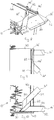
- the side deflector plate 14 includes an inner plate member 20 and an outer plate member 22, which in this embodiment are connected together by a pair of bolts 24, which pass through respective bolt holes in the inner plate member 20 and an elongate slot 28 in the outer plate member 22.
- This mechanism allows the outer plate member 22 to slide relative to the inner plate member 20, between an unextended configuration shown in Figures 3 and 5 and an extended configuration shown in Figures 4 and 6 .
- the inner plate member 20 is attached to a pivot mechanism, for example comprising a hinge 30, which allows pivoting movement of the side deflector plate 14 about the pivot axis X of the hinge.
- the pivot axis is substantially normal to the plane of crop flow through the swathing unit, for example within 30° relative to the plane of crop flow.
- a control pin 32 is attached to the outer plate member 22. The control pin 32 may be used to adjust the position of the outer plate member 22 relative to the inner plate member 20, thereby adjusting the overall length of the side deflector plate 14 in a direction radial to the pivot axis of the hinge 30, for example within 30° relative to a line that is radial to the pivot axis.
- the side deflector plate 14 has a profile comprising a substantially vertical middle part 34, a lower part 36 that is inclined inwards (i.e. towards the centre line of the swathing unit 12) at an angle of about 45° relative to the vertical, and a small upper part 38 that is also inclined inwards at an angle of about 45° relative to the vertical.
- the inner and outer plate members 20, 22 both have a similar profile, allowing them to slide relative to one another in a substantially horizontal direction.
- the side deflector plate 14 is attached through the hinge 30 to a side frame element 40 of the swathing unit 12. This allows the side deflector plate 14 to pivot between a wide swathing configuration 14' in which the plate is pivoted outwards to lie parallel to the side frame element 40, and a narrow swath configuration 14" in which it is pivoted inwards towards the centre line of the swathing unit 12.
- the control pin 32 extends upwards through a slot 42 in an upper frame element 44 of the swathing unit 12 and is attached by a screw thread to a clamping knob 46.
- the slot 42 is straight and extends in a direction perpendicular to the working direction of the agricultural mower 4. It should be understood however that the slot 42 may alternatively be curved and/or it may be set at a different angle relative to the working direction of the agricultural mower 4.
- the side deflector plate 14 may be adjusted between the wide swathing configuration 14' and the narrow swathing configuration 14" by pushing the knob 46 inwards or outwards so that the control pin 32 slides along the slot 42 between an inner position of the knob 46" and an outer position 46'.
- the side deflector plate 14 can then be fixed in the selected position (in either the narrow swathing configuration or the wide swathing configuration, or at an intermediate position) by turning the screw threaded clamping knob 46 to clamp the plate 14 against the upper frame element 44.
- Moving the control pin 32 along the slot 42 also causes sliding movement of the outer plate member 22 relative to the inner plate member 20, which changes the overall length of the side deflector plate 14 in a direction substantially radial to the pivot axis X of the hinge 30.
- the distance from the inner end 42" of the slot 42 to the pivot axis X is greater than the distance from the outer end 42' to the pivot axis X. Therefore, when the slide deflector plate 14 is in the wide swathing configuration 14' the length of the side deflector plate is reduced, and when the side deflector plate 14 is in the narrow swathing configuration 14" the length of the plate is increased.
- Adjusting the position of the side deflector plate 14 is therefore a very simple operation, involving loosening the knob 46, sliding the knob inwards or outwards as required, and then re-tightening the knob. This simultaneously adjusts both the angular position and the length of the side deflector plate 14, and ensures that the length of the side deflector plate 14 is adjusted proportionally with the angle of the plate. This provides the advantage that the spacing between the top edge of the side deflector plate 14 and the underside of the rear plate 16 is maintained at or near a constant value.
- a further advantage of this arrangement is that it can be easily adapted to automatic or semi-automatic operation, using a linear actuator such as a hydraulic ram to adjust the position of the control pin 32. Only a single actuator is then required to adjust both the angle and the length of the side deflector plate 14.
Landscapes
- Life Sciences & Earth Sciences (AREA)
- Environmental Sciences (AREA)
- Harvester Elements (AREA)
Claims (16)
- Unité d'andainage (12) destinée à une faucheuse agricole (4), l'unité d'andainage comprenant au moins une plaque déflectrice latérale (14) qui définit un côté d'une ouverture de décharge (18) et qui est réglable entre une configuration d'andain large (14') et une configuration d'andain étroit (14"),
la plaque déflectrice latérale étant fixée à un mécanisme de pivot (30) et étant réglable angulairement autour d'un axe de pivot (X) du mécanisme de pivot entre une position interne et une position externe, et la plaque déflectrice latérale (14) comprenant un premier élément de plaque (20) qui est fixé au mécanisme de pivot, caractérisée en ce que la plaque déflectrice latérale (14) comprend en outre un second élément de plaque (22) qui est fixé au premier élément de plaque et qui est réglable par rapport au premier élément de plaque pour régler la longueur totale de la plaque déflectrice latérale (14), et le second élément de plaque (22) étant fixé à un élément de commande (32) qui coopère avec un élément de guidage (42) pour commander le réglage de la longueur et la position angulaire de la plaque déflectrice latérale (14),
le déplacement de l'élément de commande par rapport à l'élément de guidage entraînant le réglage simultané de la longueur et de la position angulaire de la plaque déflectrice latérale. - Unité d'andainage selon la revendication 1, l'élément de guidage (42) étant conçu de sorte que, lorsque la plaque déflectrice latérale (14) est dans la configuration d'andain étroit (14"), la plaque déflectrice latérale est située dans la position interne et a une longueur étendue, et lorsque la plaque déflectrice latérale est dans la configuration d'andain large (14'), la plaque déflectrice latérale est située dans la position externe et a une longueur non étendue.
- Unité d'andainage selon la revendication 1 ou 2, l'axe de pivotement (X) étant sensiblement perpendiculaire au plan de flux de récolte à travers l'unité d'andainage.
- Unité d'andainage selon l'une quelconque des revendications précédentes, la longueur de la plaque déflectrice latérale (14) étant réglable dans une direction sensiblement radiale par rapport à l'axe de pivotement.
- Unité d'andainage selon l'une quelconque des revendications précédentes, les premier et second éléments de plaque (20, 22) de la plaque déflectrice latérale étant réglables télescopiquement.
- Unité d'andainage selon l'une quelconque des revendications précédentes, les premier et second éléments de plaque (20, 22) de la plaque déflectrice latérale ayant des profils similaires.
- Unité d'andainage selon l'une quelconque des revendications précédentes, les premier et second éléments de plaque (20, 22) de la plaque déflectrice latérale étant conçus pour effectuer un mouvement relatif coulissant.
- Unité d'andainage selon l'une quelconque des revendications précédentes, l'élément de commande comprenant une goupille de commande (32) fixée au second élément de plaque (22), et l'élément de guidage comprenant une fente allongée (42) ayant une extrémité interne (42") et une extrémité externe (42'), la goupille de commande s'étendant à travers la fente allongée et étant réglable sur la longueur de la fente entre l'extrémité interne et l'extrémité externe.
- Unité d'andainage selon la revendication 8, l'extrémité interne (42") de la fente allongée (42) étant située plus loin de l'axe de pivotement (X) que l'extrémité externe (42') de la fente allongée.
- Unité d'andainage selon la revendication 8 ou 9, la fente allongée (42) s'étendant dans une direction sensiblement perpendiculaire à la direction de travail de l'unité d'andainage.
- Unité d'andainage selon l'une quelconque des revendications précédentes, l'élément de commande comprenant un élément de verrouillage (46) pour le verrouiller dans une position choisie par rapport à l'élément de guidage.
- Unité d'andainage selon l'une quelconque des revendications précédentes, l'élément de commande comprenant un actionneur pour régler sa position par rapport à l'élément de guidage.
- Unité d'andainage selon l'une quelconque des revendications précédentes, comprenant des première et seconde plaques déflectrices latérales (14) situées aux extrémités opposées de l'unité d'andainage (12), qui définissent des premier et second côtés de l'ouverture de décharge (18).
- Unité d'andainage selon l'une quelconque des revendications précédentes, comprenant en outre une plaque arrière (16) qui s'étend sur la largeur de l'unité d'andainage (12) au-dessus de la ou des plaques déflectrices latérales (14).
- Faucheuse agricole (4) qui comprend une unité de fauche (8) et une unité d'andainage (12) selon l'une quelconque des revendications précédentes.
- Faucheuse agricole selon la revendication 15, comprenant en outre une unité de conditionnement (10) située de manière opérationnelle entre l'unité de fauche (8) et l'unité d'andainage (12).
Priority Applications (8)
| Application Number | Priority Date | Filing Date | Title |
|---|---|---|---|
| ES15192106.1T ES2666828T3 (es) | 2015-10-29 | 2015-10-29 | Unidad hileradora |
| EP15192106.1A EP3162182B1 (fr) | 2015-10-29 | 2015-10-29 | Unité d'andainage |
| DK15192106.1T DK3162182T3 (en) | 2015-10-29 | 2015-10-29 | SWATHING UNIT |
| US15/771,681 US10813283B2 (en) | 2015-10-29 | 2016-09-26 | Swathing unit |
| CA2999117A CA2999117C (fr) | 2015-10-29 | 2016-09-26 | Unite d'andainage |
| NZ741105A NZ741105A (en) | 2015-10-29 | 2016-09-26 | Swathing unit |
| AU2016345583A AU2016345583B2 (en) | 2015-10-29 | 2016-09-26 | Swathing unit |
| PCT/EP2016/072875 WO2017071898A1 (fr) | 2015-10-29 | 2016-09-26 | Unité d'andainage |
Applications Claiming Priority (1)
| Application Number | Priority Date | Filing Date | Title |
|---|---|---|---|
| EP15192106.1A EP3162182B1 (fr) | 2015-10-29 | 2015-10-29 | Unité d'andainage |
Publications (2)
| Publication Number | Publication Date |
|---|---|
| EP3162182A1 EP3162182A1 (fr) | 2017-05-03 |
| EP3162182B1 true EP3162182B1 (fr) | 2018-02-28 |
Family
ID=54360996
Family Applications (1)
| Application Number | Title | Priority Date | Filing Date |
|---|---|---|---|
| EP15192106.1A Active EP3162182B1 (fr) | 2015-10-29 | 2015-10-29 | Unité d'andainage |
Country Status (8)
| Country | Link |
|---|---|
| US (1) | US10813283B2 (fr) |
| EP (1) | EP3162182B1 (fr) |
| AU (1) | AU2016345583B2 (fr) |
| CA (1) | CA2999117C (fr) |
| DK (1) | DK3162182T3 (fr) |
| ES (1) | ES2666828T3 (fr) |
| NZ (1) | NZ741105A (fr) |
| WO (1) | WO2017071898A1 (fr) |
Families Citing this family (1)
| Publication number | Priority date | Publication date | Assignee | Title |
|---|---|---|---|---|
| PL3731621T3 (pl) * | 2017-12-27 | 2022-05-23 | Agco Corporation | Rolniczy podbieracz prasy do belowania z regulacją boczną |
Family Cites Families (26)
| Publication number | Priority date | Publication date | Assignee | Title |
|---|---|---|---|---|
| US3241300A (en) * | 1964-03-17 | 1966-03-22 | Hesston Mfg Company Inc | Windrower-conditioner |
| US3543491A (en) * | 1968-06-03 | 1970-12-01 | Sperry Rand Corp | Windrow baffle for crop harvesting machines |
| US3841070A (en) * | 1972-08-02 | 1974-10-15 | Int Harvester Co | Windrow placement device and harvesting method |
| US3683602A (en) * | 1970-12-16 | 1972-08-15 | Int Harvester Co | Crop aerating mechanism for harvesters |
| US3716972A (en) * | 1971-07-12 | 1973-02-20 | Hesston Corp | Mowing, conditioning and windrowing machine and method |
| US3803821A (en) * | 1973-01-18 | 1974-04-16 | Int Harvester Co | Self-adjusting crop deflector |
| US3911649A (en) * | 1973-09-25 | 1975-10-14 | Int Harvester Co | Windrow placement device and harvesting method |
| US4099364A (en) * | 1976-11-04 | 1978-07-11 | Owatonna Manufacturing Company, Inc. | Fluffer shield system for crop harvester |
| US5778647A (en) * | 1996-06-25 | 1998-07-14 | New Holland North America, Inc. | Disc mower conditioner |
| US5930988A (en) * | 1997-07-18 | 1999-08-03 | Hay & Forage Industries | On-the-go from the tractor seat windrow adjustment |
| DK173593B1 (da) * | 1998-11-16 | 2001-04-23 | Freudendahl J Fab As | Slåmaskine |
| DE10064356A1 (de) * | 2000-12-21 | 2002-07-11 | Claas Selbstfahr Erntemasch | Vorrichtung und Verfahren zur Erntegutförderung in landwirtschaftlichen Arbeitsmaschinen |
| CA2427755A1 (fr) * | 2003-05-05 | 2004-11-05 | Macdon Industries Ltd. | Systeme de formation d'andains pour bec cueilleur de recolte |
| FR2855012B1 (fr) * | 2003-05-23 | 2006-06-02 | Kuhn Sa | Dispositif de traitement du fourrage muni de deux elements de guidage |
| US20060123764A1 (en) * | 2004-12-09 | 2006-06-15 | Mclean Kenneth W | Adjustable windrower shields |
| US7635299B2 (en) * | 2007-09-28 | 2009-12-22 | Cnh America Llc | Windrow forming construction |
| DE102010029191A1 (de) * | 2010-05-20 | 2011-11-24 | Deere & Company | Mähaufbereiter mit Breitstreuvorrichtung |
| US20110302897A1 (en) * | 2010-06-11 | 2011-12-15 | Curtis Hoffman | Swathgate with adjustable crop guides and method of crop distribution |
| US20140083071A1 (en) * | 2012-09-25 | 2014-03-27 | Ii Jeffrey Fay | Active steering windrow shields |
| US9894837B2 (en) * | 2012-10-04 | 2018-02-20 | Cnh Industrial America Llc | Adjustable windrow assembly for an agricultural vehicle |
| US9565800B2 (en) * | 2014-09-08 | 2017-02-14 | Cnh Industrial America Llc | Windrow shield control system for a header of an agricultural harvester |
| FR3039966B1 (fr) * | 2015-08-12 | 2018-02-09 | Kuhn S.A. | Dispositif de formation d'un andain |
| US10772257B2 (en) * | 2017-05-12 | 2020-09-15 | Deere & Company | Multi mode crop forming shield adjustment mechanism |
| US20180325032A1 (en) * | 2017-05-12 | 2018-11-15 | Deere & Company | System for automatically controlling conditioning and windrowing arrangements of a work vehicle |
| CA3009724C (fr) * | 2017-07-24 | 2021-03-23 | Agco Corporation | Commande automatique de planche a andains de faucheuse-andaineuse |
| US10336546B2 (en) * | 2017-09-20 | 2019-07-02 | Cnh Industrial America Llc | Windrow chute with independently movable chute sections |
-
2015
- 2015-10-29 ES ES15192106.1T patent/ES2666828T3/es active Active
- 2015-10-29 DK DK15192106.1T patent/DK3162182T3/en active
- 2015-10-29 EP EP15192106.1A patent/EP3162182B1/fr active Active
-
2016
- 2016-09-26 US US15/771,681 patent/US10813283B2/en active Active
- 2016-09-26 WO PCT/EP2016/072875 patent/WO2017071898A1/fr active Application Filing
- 2016-09-26 AU AU2016345583A patent/AU2016345583B2/en active Active
- 2016-09-26 CA CA2999117A patent/CA2999117C/fr active Active
- 2016-09-26 NZ NZ741105A patent/NZ741105A/en unknown
Non-Patent Citations (1)
| Title |
|---|
| None * |
Also Published As
| Publication number | Publication date |
|---|---|
| US20180310473A1 (en) | 2018-11-01 |
| EP3162182A1 (fr) | 2017-05-03 |
| CA2999117C (fr) | 2022-03-01 |
| AU2016345583B2 (en) | 2021-01-21 |
| ES2666828T3 (es) | 2018-05-08 |
| CA2999117A1 (fr) | 2017-05-04 |
| DK3162182T3 (en) | 2018-05-22 |
| WO2017071898A1 (fr) | 2017-05-04 |
| NZ741105A (en) | 2022-02-25 |
| US10813283B2 (en) | 2020-10-27 |
| AU2016345583A1 (en) | 2018-04-19 |
Similar Documents
| Publication | Publication Date | Title |
|---|---|---|
| EP1961288B1 (fr) | Dispositif destiné au réglage de la position de l'organe d'accélération ultérieure dans une moissonneuse agricole | |
| EP1219164B1 (fr) | Procédé et dispositif pour convoyer des récoltes dans une machine agricole | |
| EP2829168B1 (fr) | Tondeuse | |
| US9485908B2 (en) | Secondary cutting device arrangement for an agricultural harvesting machine | |
| US20110302897A1 (en) | Swathgate with adjustable crop guides and method of crop distribution | |
| EP2863729B1 (fr) | Mécanisme de coupe | |
| US20080120956A1 (en) | Material-Guiding Device | |
| US11744184B2 (en) | Roll conditioner adjustment system for an agricultural harvesting machine | |
| EP3434097B1 (fr) | Diviseur de récolte pour une tête de coupe de moissonneuse agricole ayant de multiples rabatteurs de récolte | |
| BE1026187B1 (de) | Auswurfanordnung zur Anbringung am Ende einer Austrageinrichtung | |
| AU2016345583B2 (en) | Swathing unit | |
| EP3744168A2 (fr) | Capot de machine pour le conditionnement de cultures avec planche à andains intégrée | |
| DE102015218726A1 (de) | Strohhäcksler für einen Mähdrescher mit Gegenmessern und Reibleiste | |
| EP3659421A1 (fr) | Tête de récolte dotée de vis sans fin transversale réglable | |
| WO2019055743A1 (fr) | Ensemble réglage de piste de came pour un rabatteur de récolte | |
| EP4056021A2 (fr) | Barre de coupe | |
| NL1026257C1 (nl) | Gewasbewerkingsinrichting en maaier met een dergelijke gewasbewerkingsinrichting. | |
| DE102021104114A1 (de) | Mähdrescher mit einer Häckselvorrichtung | |
| DE102014014650B4 (de) | Vorsatzgerät für eine landwirtschaftliche Erntemaschine |
Legal Events
| Date | Code | Title | Description |
|---|---|---|---|
| PUAI | Public reference made under article 153(3) epc to a published international application that has entered the european phase |
Free format text: ORIGINAL CODE: 0009012 |
|
| STAA | Information on the status of an ep patent application or granted ep patent |
Free format text: STATUS: REQUEST FOR EXAMINATION WAS MADE |
|
| 17P | Request for examination filed |
Effective date: 20161013 |
|
| AK | Designated contracting states |
Kind code of ref document: A1 Designated state(s): AL AT BE BG CH CY CZ DE DK EE ES FI FR GB GR HR HU IE IS IT LI LT LU LV MC MK MT NL NO PL PT RO RS SE SI SK SM TR |
|
| AX | Request for extension of the european patent |
Extension state: BA ME |
|
| REG | Reference to a national code |
Ref country code: DE Ref legal event code: R079 Ref document number: 602015008295 Country of ref document: DE Free format text: PREVIOUS MAIN CLASS: A01D0034660000 Ipc: A01D0057260000 |
|
| RIC1 | Information provided on ipc code assigned before grant |
Ipc: A01D 57/26 20060101AFI20171012BHEP Ipc: A01D 34/49 20060101ALI20171012BHEP Ipc: A01D 34/71 20060101ALI20171012BHEP |
|
| GRAP | Despatch of communication of intention to grant a patent |
Free format text: ORIGINAL CODE: EPIDOSNIGR1 |
|
| STAA | Information on the status of an ep patent application or granted ep patent |
Free format text: STATUS: GRANT OF PATENT IS INTENDED |
|
| INTG | Intention to grant announced |
Effective date: 20171205 |
|
| GRAS | Grant fee paid |
Free format text: ORIGINAL CODE: EPIDOSNIGR3 |
|
| GRAA | (expected) grant |
Free format text: ORIGINAL CODE: 0009210 |
|
| STAA | Information on the status of an ep patent application or granted ep patent |
Free format text: STATUS: THE PATENT HAS BEEN GRANTED |
|
| AK | Designated contracting states |
Kind code of ref document: B1 Designated state(s): AL AT BE BG CH CY CZ DE DK EE ES FI FR GB GR HR HU IE IS IT LI LT LU LV MC MK MT NL NO PL PT RO RS SE SI SK SM TR |
|
| REG | Reference to a national code |
Ref country code: GB Ref legal event code: FG4D Ref country code: CH Ref legal event code: EP |
|
| REG | Reference to a national code |
Ref country code: AT Ref legal event code: REF Ref document number: 973103 Country of ref document: AT Kind code of ref document: T Effective date: 20180315 |
|
| REG | Reference to a national code |
Ref country code: IE Ref legal event code: FG4D |
|
| REG | Reference to a national code |
Ref country code: DE Ref legal event code: R096 Ref document number: 602015008295 Country of ref document: DE |
|
| REG | Reference to a national code |
Ref country code: ES Ref legal event code: FG2A Ref document number: 2666828 Country of ref document: ES Kind code of ref document: T3 Effective date: 20180508 |
|
| REG | Reference to a national code |
Ref country code: NL Ref legal event code: FP |
|
| REG | Reference to a national code |
Ref country code: DK Ref legal event code: T3 Effective date: 20180516 Ref country code: SE Ref legal event code: TRGR |
|
| REG | Reference to a national code |
Ref country code: LT Ref legal event code: MG4D |
|
| PG25 | Lapsed in a contracting state [announced via postgrant information from national office to epo] |
Ref country code: HR Free format text: LAPSE BECAUSE OF FAILURE TO SUBMIT A TRANSLATION OF THE DESCRIPTION OR TO PAY THE FEE WITHIN THE PRESCRIBED TIME-LIMIT Effective date: 20180228 Ref country code: NO Free format text: LAPSE BECAUSE OF FAILURE TO SUBMIT A TRANSLATION OF THE DESCRIPTION OR TO PAY THE FEE WITHIN THE PRESCRIBED TIME-LIMIT Effective date: 20180528 Ref country code: LT Free format text: LAPSE BECAUSE OF FAILURE TO SUBMIT A TRANSLATION OF THE DESCRIPTION OR TO PAY THE FEE WITHIN THE PRESCRIBED TIME-LIMIT Effective date: 20180228 Ref country code: CY Free format text: LAPSE BECAUSE OF FAILURE TO SUBMIT A TRANSLATION OF THE DESCRIPTION OR TO PAY THE FEE WITHIN THE PRESCRIBED TIME-LIMIT Effective date: 20180228 |
|
| PG25 | Lapsed in a contracting state [announced via postgrant information from national office to epo] |
Ref country code: BG Free format text: LAPSE BECAUSE OF FAILURE TO SUBMIT A TRANSLATION OF THE DESCRIPTION OR TO PAY THE FEE WITHIN THE PRESCRIBED TIME-LIMIT Effective date: 20180528 Ref country code: GR Free format text: LAPSE BECAUSE OF FAILURE TO SUBMIT A TRANSLATION OF THE DESCRIPTION OR TO PAY THE FEE WITHIN THE PRESCRIBED TIME-LIMIT Effective date: 20180529 Ref country code: LV Free format text: LAPSE BECAUSE OF FAILURE TO SUBMIT A TRANSLATION OF THE DESCRIPTION OR TO PAY THE FEE WITHIN THE PRESCRIBED TIME-LIMIT Effective date: 20180228 Ref country code: RS Free format text: LAPSE BECAUSE OF FAILURE TO SUBMIT A TRANSLATION OF THE DESCRIPTION OR TO PAY THE FEE WITHIN THE PRESCRIBED TIME-LIMIT Effective date: 20180228 |
|
| REG | Reference to a national code |
Ref country code: FR Ref legal event code: PLFP Year of fee payment: 4 |
|
| PG25 | Lapsed in a contracting state [announced via postgrant information from national office to epo] |
Ref country code: RO Free format text: LAPSE BECAUSE OF FAILURE TO SUBMIT A TRANSLATION OF THE DESCRIPTION OR TO PAY THE FEE WITHIN THE PRESCRIBED TIME-LIMIT Effective date: 20180228 Ref country code: EE Free format text: LAPSE BECAUSE OF FAILURE TO SUBMIT A TRANSLATION OF THE DESCRIPTION OR TO PAY THE FEE WITHIN THE PRESCRIBED TIME-LIMIT Effective date: 20180228 Ref country code: AL Free format text: LAPSE BECAUSE OF FAILURE TO SUBMIT A TRANSLATION OF THE DESCRIPTION OR TO PAY THE FEE WITHIN THE PRESCRIBED TIME-LIMIT Effective date: 20180228 Ref country code: PL Free format text: LAPSE BECAUSE OF FAILURE TO SUBMIT A TRANSLATION OF THE DESCRIPTION OR TO PAY THE FEE WITHIN THE PRESCRIBED TIME-LIMIT Effective date: 20180228 |
|
| REG | Reference to a national code |
Ref country code: DE Ref legal event code: R097 Ref document number: 602015008295 Country of ref document: DE |
|
| PG25 | Lapsed in a contracting state [announced via postgrant information from national office to epo] |
Ref country code: SK Free format text: LAPSE BECAUSE OF FAILURE TO SUBMIT A TRANSLATION OF THE DESCRIPTION OR TO PAY THE FEE WITHIN THE PRESCRIBED TIME-LIMIT Effective date: 20180228 Ref country code: CZ Free format text: LAPSE BECAUSE OF FAILURE TO SUBMIT A TRANSLATION OF THE DESCRIPTION OR TO PAY THE FEE WITHIN THE PRESCRIBED TIME-LIMIT Effective date: 20180228 Ref country code: SM Free format text: LAPSE BECAUSE OF FAILURE TO SUBMIT A TRANSLATION OF THE DESCRIPTION OR TO PAY THE FEE WITHIN THE PRESCRIBED TIME-LIMIT Effective date: 20180228 |
|
| PLBE | No opposition filed within time limit |
Free format text: ORIGINAL CODE: 0009261 |
|
| STAA | Information on the status of an ep patent application or granted ep patent |
Free format text: STATUS: NO OPPOSITION FILED WITHIN TIME LIMIT |
|
| 26N | No opposition filed |
Effective date: 20181129 |
|
| REG | Reference to a national code |
Ref country code: CH Ref legal event code: PL |
|
| REG | Reference to a national code |
Ref country code: BE Ref legal event code: MM Effective date: 20181031 |
|
| PG25 | Lapsed in a contracting state [announced via postgrant information from national office to epo] |
Ref country code: LU Free format text: LAPSE BECAUSE OF NON-PAYMENT OF DUE FEES Effective date: 20181029 Ref country code: MC Free format text: LAPSE BECAUSE OF FAILURE TO SUBMIT A TRANSLATION OF THE DESCRIPTION OR TO PAY THE FEE WITHIN THE PRESCRIBED TIME-LIMIT Effective date: 20180228 |
|
| PG25 | Lapsed in a contracting state [announced via postgrant information from national office to epo] |
Ref country code: CH Free format text: LAPSE BECAUSE OF NON-PAYMENT OF DUE FEES Effective date: 20181031 Ref country code: LI Free format text: LAPSE BECAUSE OF NON-PAYMENT OF DUE FEES Effective date: 20181031 Ref country code: BE Free format text: LAPSE BECAUSE OF NON-PAYMENT OF DUE FEES Effective date: 20181031 |
|
| PG25 | Lapsed in a contracting state [announced via postgrant information from national office to epo] |
Ref country code: MT Free format text: LAPSE BECAUSE OF NON-PAYMENT OF DUE FEES Effective date: 20181029 |
|
| PG25 | Lapsed in a contracting state [announced via postgrant information from national office to epo] |
Ref country code: TR Free format text: LAPSE BECAUSE OF FAILURE TO SUBMIT A TRANSLATION OF THE DESCRIPTION OR TO PAY THE FEE WITHIN THE PRESCRIBED TIME-LIMIT Effective date: 20180228 |
|
| PG25 | Lapsed in a contracting state [announced via postgrant information from national office to epo] |
Ref country code: PT Free format text: LAPSE BECAUSE OF FAILURE TO SUBMIT A TRANSLATION OF THE DESCRIPTION OR TO PAY THE FEE WITHIN THE PRESCRIBED TIME-LIMIT Effective date: 20180228 |
|
| PG25 | Lapsed in a contracting state [announced via postgrant information from national office to epo] |
Ref country code: HU Free format text: LAPSE BECAUSE OF FAILURE TO SUBMIT A TRANSLATION OF THE DESCRIPTION OR TO PAY THE FEE WITHIN THE PRESCRIBED TIME-LIMIT; INVALID AB INITIO Effective date: 20151029 Ref country code: MK Free format text: LAPSE BECAUSE OF NON-PAYMENT OF DUE FEES Effective date: 20180228 |
|
| PG25 | Lapsed in a contracting state [announced via postgrant information from national office to epo] |
Ref country code: IS Free format text: LAPSE BECAUSE OF FAILURE TO SUBMIT A TRANSLATION OF THE DESCRIPTION OR TO PAY THE FEE WITHIN THE PRESCRIBED TIME-LIMIT Effective date: 20180628 |
|
| PG25 | Lapsed in a contracting state [announced via postgrant information from national office to epo] |
Ref country code: SI Free format text: LAPSE BECAUSE OF NON-PAYMENT OF DUE FEES Effective date: 20181029 |
|
| REG | Reference to a national code |
Ref country code: AT Ref legal event code: UEP Ref document number: 973103 Country of ref document: AT Kind code of ref document: T Effective date: 20180228 |
|
| P01 | Opt-out of the competence of the unified patent court (upc) registered |
Effective date: 20230525 |
|
| PGFP | Annual fee paid to national office [announced via postgrant information from national office to epo] |
Ref country code: NL Payment date: 20231019 Year of fee payment: 9 |
|
| PGFP | Annual fee paid to national office [announced via postgrant information from national office to epo] |
Ref country code: GB Payment date: 20231020 Year of fee payment: 9 |
|
| PGFP | Annual fee paid to national office [announced via postgrant information from national office to epo] |
Ref country code: ES Payment date: 20231227 Year of fee payment: 9 |
|
| PGFP | Annual fee paid to national office [announced via postgrant information from national office to epo] |
Ref country code: SE Payment date: 20231019 Year of fee payment: 9 Ref country code: IT Payment date: 20231026 Year of fee payment: 9 Ref country code: IE Payment date: 20231023 Year of fee payment: 9 Ref country code: FR Payment date: 20231026 Year of fee payment: 9 Ref country code: FI Payment date: 20231020 Year of fee payment: 9 Ref country code: DK Payment date: 20231024 Year of fee payment: 9 Ref country code: DE Payment date: 20231020 Year of fee payment: 9 Ref country code: AT Payment date: 20231020 Year of fee payment: 9 |