EP3161946B1 - Antriebseinheit - Google Patents
Antriebseinheit Download PDFInfo
- Publication number
- EP3161946B1 EP3161946B1 EP15730789.3A EP15730789A EP3161946B1 EP 3161946 B1 EP3161946 B1 EP 3161946B1 EP 15730789 A EP15730789 A EP 15730789A EP 3161946 B1 EP3161946 B1 EP 3161946B1
- Authority
- EP
- European Patent Office
- Prior art keywords
- drive shaft
- drive
- bearing
- contact
- drive unit
- Prior art date
- Legal status (The legal status is an assumption and is not a legal conclusion. Google has not performed a legal analysis and makes no representation as to the accuracy of the status listed.)
- Active
Links
Images



Classifications
-
- H—ELECTRICITY
- H02—GENERATION; CONVERSION OR DISTRIBUTION OF ELECTRIC POWER
- H02K—DYNAMO-ELECTRIC MACHINES
- H02K7/00—Arrangements for handling mechanical energy structurally associated with dynamo-electric machines, e.g. structural association with mechanical driving motors or auxiliary dynamo-electric machines
- H02K7/10—Structural association with clutches, brakes, gears, pulleys or mechanical starters
- H02K7/116—Structural association with clutches, brakes, gears, pulleys or mechanical starters with gears
- H02K7/1163—Structural association with clutches, brakes, gears, pulleys or mechanical starters with gears where at least two gears have non-parallel axes without having orbital motion
- H02K7/1166—Structural association with clutches, brakes, gears, pulleys or mechanical starters with gears where at least two gears have non-parallel axes without having orbital motion comprising worm and worm-wheel
-
- F—MECHANICAL ENGINEERING; LIGHTING; HEATING; WEAPONS; BLASTING
- F16—ENGINEERING ELEMENTS AND UNITS; GENERAL MEASURES FOR PRODUCING AND MAINTAINING EFFECTIVE FUNCTIONING OF MACHINES OR INSTALLATIONS; THERMAL INSULATION IN GENERAL
- F16H—GEARING
- F16H57/00—General details of gearing
- F16H57/02—Gearboxes; Mounting gearing therein
- F16H57/021—Shaft support structures, e.g. partition walls, bearing eyes, casing walls or covers with bearings
-
- F—MECHANICAL ENGINEERING; LIGHTING; HEATING; WEAPONS; BLASTING
- F16—ENGINEERING ELEMENTS AND UNITS; GENERAL MEASURES FOR PRODUCING AND MAINTAINING EFFECTIVE FUNCTIONING OF MACHINES OR INSTALLATIONS; THERMAL INSULATION IN GENERAL
- F16C—SHAFTS; FLEXIBLE SHAFTS; ELEMENTS OR CRANKSHAFT MECHANISMS; ROTARY BODIES OTHER THAN GEARING ELEMENTS; BEARINGS
- F16C19/00—Bearings with rolling contact, for exclusively rotary movement
- F16C19/54—Systems consisting of a plurality of bearings with rolling friction
-
- F—MECHANICAL ENGINEERING; LIGHTING; HEATING; WEAPONS; BLASTING
- F16—ENGINEERING ELEMENTS AND UNITS; GENERAL MEASURES FOR PRODUCING AND MAINTAINING EFFECTIVE FUNCTIONING OF MACHINES OR INSTALLATIONS; THERMAL INSULATION IN GENERAL
- F16C—SHAFTS; FLEXIBLE SHAFTS; ELEMENTS OR CRANKSHAFT MECHANISMS; ROTARY BODIES OTHER THAN GEARING ELEMENTS; BEARINGS
- F16C27/00—Elastic or yielding bearings or bearing supports, for exclusively rotary movement
- F16C27/02—Sliding-contact bearings
-
- F—MECHANICAL ENGINEERING; LIGHTING; HEATING; WEAPONS; BLASTING
- F16—ENGINEERING ELEMENTS AND UNITS; GENERAL MEASURES FOR PRODUCING AND MAINTAINING EFFECTIVE FUNCTIONING OF MACHINES OR INSTALLATIONS; THERMAL INSULATION IN GENERAL
- F16H—GEARING
- F16H1/00—Toothed gearings for conveying rotary motion
- F16H1/02—Toothed gearings for conveying rotary motion without gears having orbital motion
- F16H1/04—Toothed gearings for conveying rotary motion without gears having orbital motion involving only two intermeshing members
- F16H1/12—Toothed gearings for conveying rotary motion without gears having orbital motion involving only two intermeshing members with non-parallel axes
- F16H1/16—Toothed gearings for conveying rotary motion without gears having orbital motion involving only two intermeshing members with non-parallel axes comprising worm and worm-wheel
-
- F—MECHANICAL ENGINEERING; LIGHTING; HEATING; WEAPONS; BLASTING
- F16—ENGINEERING ELEMENTS AND UNITS; GENERAL MEASURES FOR PRODUCING AND MAINTAINING EFFECTIVE FUNCTIONING OF MACHINES OR INSTALLATIONS; THERMAL INSULATION IN GENERAL
- F16H—GEARING
- F16H55/00—Elements with teeth or friction surfaces for conveying motion; Worms, pulleys or sheaves for gearing mechanisms
- F16H55/02—Toothed members; Worms
- F16H55/22—Toothed members; Worms for transmissions with crossing shafts, especially worms, worm-gears
- F16H55/24—Special devices for taking up backlash
-
- F—MECHANICAL ENGINEERING; LIGHTING; HEATING; WEAPONS; BLASTING
- F16—ENGINEERING ELEMENTS AND UNITS; GENERAL MEASURES FOR PRODUCING AND MAINTAINING EFFECTIVE FUNCTIONING OF MACHINES OR INSTALLATIONS; THERMAL INSULATION IN GENERAL
- F16H—GEARING
- F16H57/00—General details of gearing
- F16H57/02—Gearboxes; Mounting gearing therein
- F16H57/039—Gearboxes for accommodating worm gears
-
- H—ELECTRICITY
- H02—GENERATION; CONVERSION OR DISTRIBUTION OF ELECTRIC POWER
- H02K—DYNAMO-ELECTRIC MACHINES
- H02K7/00—Arrangements for handling mechanical energy structurally associated with dynamo-electric machines, e.g. structural association with mechanical driving motors or auxiliary dynamo-electric machines
- H02K7/08—Structural association with bearings
-
- H—ELECTRICITY
- H02—GENERATION; CONVERSION OR DISTRIBUTION OF ELECTRIC POWER
- H02K—DYNAMO-ELECTRIC MACHINES
- H02K7/00—Arrangements for handling mechanical energy structurally associated with dynamo-electric machines, e.g. structural association with mechanical driving motors or auxiliary dynamo-electric machines
- H02K7/08—Structural association with bearings
- H02K7/081—Structural association with bearings specially adapted for worm gear drives
-
- F—MECHANICAL ENGINEERING; LIGHTING; HEATING; WEAPONS; BLASTING
- F16—ENGINEERING ELEMENTS AND UNITS; GENERAL MEASURES FOR PRODUCING AND MAINTAINING EFFECTIVE FUNCTIONING OF MACHINES OR INSTALLATIONS; THERMAL INSULATION IN GENERAL
- F16H—GEARING
- F16H57/00—General details of gearing
- F16H57/02—Gearboxes; Mounting gearing therein
- F16H57/021—Shaft support structures, e.g. partition walls, bearing eyes, casing walls or covers with bearings
- F16H2057/0213—Support of worm gear shafts
Definitions
- the invention relates to a drive unit according to the preamble of claim 1.
- Such a drive unit is from the DE 10 2010 064 295 A1 the applicant known.
- the known drive unit is part of a comfort drive in a motor vehicle, such as a window regulator drive, a sunroof drive, a seat adjustment drive.
- the known drive unit on both sides of a drive motor on a first and a second bearing element for supporting a drive shaft.
- the drive shaft cooperates with a worm gear with a counter toothing of a gear designed as a spur gear.
- a third bearing element is provided, which serves to absorb transversely to the longitudinal axis of the drive shaft acting forces that lead to a deflection of the drive shaft, or support.
- the known drive unit or the third bearing element has a drive shaft on its circumference, preferably with radial play encompassing portion which is connected via a flexible intermediate portion with a arranged in a receptacle of a transmission housing storage area.
- the one-piece third bearing element is sleeve-shaped with a through hole for receiving the end portion of the drive shaft.
- the space required for receiving the third bearing element limits the installation space or the possibility of an axial support for the end region of the Drive shaft or makes such an axial support is no longer possible.
- Be particularly disadvantageous is to be considered that it comes with a radial clearance between the circumference of the drive shaft and the third bearing element typically due to component tolerances to a periodic touching or striking the peripheral surface of the drive shaft on the third bearing element, which are perceived as disturbing noise can.
- the DE 10 2007 047369 A1 shows a worm gear of a steering system in which a ball bearing, in which the worm shaft is mounted, is pressed against the worm wheel. This is done by means of a movably mounted pressure piece, which is braced by means of a spring element.
- the invention has the object, a drive unit according to the preamble of claim 1 such that on the one hand requires the least possible space for receiving the third bearing element in the transmission housing, and on the other hand, a reduced noise emission and in addition the simplest possible arrangement of a device for Axialabstützung the drive shaft allows.
- This object is achieved in a drive unit with the features of claim 1, characterized in that the receptacle for the third bearing element, which serves for the lateral support of the drive shaft, arranged in the gear housing in relation to the drive shaft laterally adjacent to the drive shaft in a partial region in the circumferential direction of the drive shaft is, and that the third bearing element comprises a contact element which is arranged in constant contact with the drive shaft.
- the contact element on the side facing the drive shaft has a flat contact surface, such that the contact surface in the direction of the longitudinal axis of the drive shaft is linearly applied to the drive shaft ,
- Such a design of the contact surface of the third bearing element makes it possible, for example, to use the third bearing element only after assembly of the drive shaft in the transmission housing, so that there is greater flexibility in terms of different mounting options of the drive unit.
- the contact element of the third bearing element on the side facing the drive shaft has a concave or radiused contact surface, such that the contact surface rests in the circumferential direction of the drive shaft on the drive shaft.
- Such a design of the contact surface of the third bearing element allows an improved or enlarged system of the drive shaft on the contact surface of the third bearing element.
- the contact element is connected by at least one elastic intermediate element with a bearing portion of the third bearing element, that the bearing portion in the receptacle of the gear housing shape or is arranged clamped, and that the intermediate element generates a contact force on the contact element in the direction of the drive shaft.
- the third bearing element thus has three different functional areas: on the one hand, the contact element in constant contact with the drive shaft, the second, the intermediate element that generates the required contact force for the contact element to the drive shaft, and third
- Bearing portion which is arranged in the receptacle of the transmission housing. This structural division of the third bearing element in three functional areas makes it possible to optimally adapt the respective functional area to its respective task.
- the abutment element cooperates with a stop which limits the deflection of the abutment element in a direction perpendicular to the longitudinal axis of the drive shaft.
- the stop thus serves to protect the components of the drive unit, so that the functionality of the drive unit to the maximum deflection of the drive shaft, in which the abutment element cooperates with the stop, is ensured.
- the stop is formed on the third bearing element itself.
- the stop is formed on the gear housing.
- the at least one intermediate element extends substantially in a direction perpendicular to the longitudinal axis of the drive shaft.
- Such an arrangement or design of the intermediate element has in particular the advantage of a space in the longitudinal direction of the drive shaft space for the third bearing element, which facilitates, for example, the arrangement of a device for receiving axial forces of the drive shaft.
- the at least one intermediate element extends substantially in a direction extending parallel to the longitudinal axis of the drive shaft.
- Such an arrangement or design of the intermediate element has the advantage of an improved spring action of the contact element, as this, without increasing the space of the gear housing in a direction perpendicular to the longitudinal axis of the drive shaft direction, offers the possibility of the intermediate element, for example, with a relatively large length train.
- the transmission housing has guide portions formed by wall sections for the contact element, which extend perpendicular to the longitudinal axis of the drive shaft and interact with forming a clearance fit with side walls of the contact element.
- the gear housing has a preferably cup-shaped base element, in which the receptacle for the bearing device is formed, and that the region of the receptacle is covered by a connectable to the base element lid member, the region of the bearing element abuts.
- the abutment of the cover element takes place at least on the bearing section of the third bearing element in order to ensure a defined arrangement of the bearing section of the third bearing element in the transmission housing.
- the third bearing element can be produced, if this is designed as a one-piece plastic injection molded part. Alternatively, however, it is also conceivable that the third bearing element is formed in one piece and consists of a rubber-elastic material.
- a drive unit according to the invention is used in a comfort drive in a motor vehicle, such as a window lift drive, a sunroof drive, a seat adjustment drive, or the like.
- a comfort drive in particular has the advantage of low noise emissions and a particularly compact design.
- a comfort drive is in the context of the invention by way of example, and not limiting, a power window drive, a sunroof drive, a Wegver thoroughlysantrieb o.ä. Understood.
- the drive unit 100 has a drive motor 1 designed as an electric motor, which has a drive shaft 2 protruding from the housing of the drive motor 1.
- the drive shaft 2 of the drive motor 1 is mounted on both sides of the drive motor 1 in a first and second bearing element 3, 4 preferably designed as a ball bearing or plain bearing.
- the two bearing elements 3, 4 in each case a receptacle 5, 6 in a in the Fig. 1 only partially shown gear housing 10 recorded or arranged.
- the drive shaft 2 On the side facing away from the first bearing element 3 side of the second bearing element 4, the drive shaft 2 has a portion with a toothing 11 in the form of a worm toothing.
- the toothing 11 cooperates with a counter-toothing 12 of a gear device shown in the form of a gear 13 in the form of a gear wheel, which is formed in the form of a spur gear, and which consists of plastic.
- the gear 13 is used to transmit a torque generated by the drive motor 1 to a not shown, to be adjusted element, such as a window or a sunroof.
- the drive motor 1 facing away from end portion 15 of the drive shaft 2 cooperates with a third bearing element 20 as a support member which is adapted to the deflection of the end portion 15 of the drive shaft 1 in a direction perpendicular to the longitudinal axis 21 of the drive shaft 2, pointing away from the gear 13 direction caused by a force F between the toothing 11 and the counter-toothing 12 to limit.
- the storage device of the drive shaft 2 serving storage device 50 of the drive unit 100 thus has the three bearing elements 3, 4 and 20. Furthermore, the effect End portion 15 of the drive shaft 2 with a support means 22 together, which receives in the direction of the longitudinal axis 21 acting on the support means 22 longitudinal forces or supported.
- the support means 22 as in particular with reference to the illustration of Fig.
- a preferably made of metal support plate 23 which supports the drive shaft 2 in the axial direction via an elastic element 24 in the form of a cylindrical rubber element, for example, wherein the support plate 23 is arranged in abutting contact with the preferably crowned shaft end 25.
- the support device 22 is arranged in a receiving space 26 of the transmission housing 10.
- the third bearing element 20 of the bearing device 50 is shown in detail in a first embodiment of the invention.
- the plastic, integrally formed and produced by injection molding third bearing element 20 essentially consists of three areas:
- the first area is formed by a block-shaped contact element 28, which has a flat contact surface 29 on the drive shaft 2 side facing ,
- the contact element 28 is connected to a bearing section 35 via two intermediate elements 32, 33, which are arranged parallel to one another and are elastically deformable in the direction of the double arrow 31.
- the substantially plate-shaped bearing portion 35 has perpendicular to a rear side 36 a web-shaped stop member 37, which limits the deflection of the abutment member 28 toward the bearing portion 35, ie perpendicular to the longitudinal axis 21 of the drive shaft 2, wherein the stop member 37 in alignment with the Investment element 28 is arranged.
- the bearing portion 35 is received in a receptacle 38 of the gear housing 10 laterally adjacent to the drive shaft 2 over a portion of the drive shaft 2 in the circumferential direction, at least partially positive or clamped.
- the two intermediate elements 32, 33 are arranged with play in the receptacle 38 in order to allow a deformation of the intermediate elements 32, 33.
- the receptacle 38 has serving as guide portions wall portions 39, 40 which cooperate via a clearance with side walls 41, 42 of the contact element 28, and in a deflection of the contact element 28 in the direction of the stop element 37 a guide of the contact element 28 in cause a perpendicular to the longitudinal axis 21 of the drive shaft 2 extending direction.
- the contact element 28 It is essential for the contact element 28 that the arrangement of the third bearing element 20 in the receptacle 38 is such that the contact element 28 is acted upon by a contact force on the circumference of the drive shaft 2 via the two intermediate elements 32, 33, so that the contact element 28 with its Contact surface 29 is always arranged in abutting contact with the peripheral surface of the drive shaft 2.
- the contact takes place parallel to the longitudinal axis 21 of the drive shaft 2 linear over the width of the contact surface 29th
- the receptacle 38 for the third bearing element 20 is formed in a preferably shell-shaped base member 43 of the gear housing 10, which is also preferably produced by plastic injection molding.
- the base element 43 is at least in the region of the third bearing element 20 of a in the Fig. 4 recognizable cover member 44 covered.
- the lid member 44 has a strip-shaped support body 45 which rests in the mounted state of the gear housing 10 with the base member 43 at the top of the bearing portion 35 and thus positioned or fixed in the receptacle 38.
- a modified third bearing element 20a which differs from the bearing element 20 in that the abutment element 28a and the bearing portion 35a are connected via a single intermediate element 46.
- the intermediate element 46 extends in the installed state in the transmission housing 10 substantially in a direction parallel to the longitudinal axis 21 of the drive shaft 2 extending direction, so that the receptacle 38a in the transmission housing 10 substantially ( in contrast to the receptacle 38 for the third bearing element 20) extends parallel to the longitudinal axis 21 of the drive shaft 2.
- a part of the receptacle 38 extends laterally next to the support device 22.
- the contact element 28a has a flat contact surface 29a for abutment with the peripheral surface of the drive shaft 2 and is so through the intermediate member 46 in the direction of the drive shaft. 2 kraftbeaufschlagt that a permanent contact of the bearing surface 29a is made possible on the drive shaft 2.
- the abutment element 28a has on the side facing away from the abutment surface 29a on a flat rear side 47, which cooperates with a formed by a portion of the receptacle 38a abutment surface 48 to limit the movement of the abutment element 28a at a deflection of the drive shaft 2.
- the third bearing element 20b of Fig. 7 is at least substantially identical to the third bearing element 20a according to the FIGS. 5 and 6 educated. Differences arise only in the (lateral) guidance of the contact elements 28a, 28b. While in the contact element 28a according to the Fig. 5 the abutment element 28a takes place in the region of a relatively narrow, web-shaped region 49 on wall sections 39a, 40a of the receptacle 38a, the guide element 28b is guided over an enlarged region of the abutment element 28b extending in a direction perpendicular to the longitudinal axis 21.
- the one side surface 51 of the abutment element 28b is formed extended and extends over both the region 49, as well as over a widened area 52 formed area 52.
- the side surface 51 cooperates with a relative to the wall portion 40a widened wall portion 40b together.
- a third bearing element 20c which differs from the bearing element 20a or 20b substantially in that the abutment element 28c has a concave or radiused R contact surface 29c, which partially applied in the circumferential direction of the drive shaft 2, for example over an angular range of approx. 150 °.
- the contact surface 29c thus encompasses the peripheral surface of the drive shaft 2 in a form-fitting manner and thus secures or supports the drive shaft 2 in a direction perpendicular to the deflection of the drive shaft 2 in a deflection of the drive shaft 2.
- Opposite the flat contact surfaces 29, 29a is the contact surface 29c thus over a larger area on the peripheral surface of the drive shaft 2.
- the third bearing element 20d is formed substantially block-shaped. It can either be integrally formed on the transmission housing 10 when the transmission housing 10 from a suitable material, or be designed as a separate component. In this case, it is also arranged in a corresponding receptacle of the transmission housing 10.
- the third bearing element 20d has two interacting, each block-shaped sections in the form of a contact element 28d and a bearing portion 35d, which are integrally connected to each other via a web-like, elastic intermediate element 53. Between the abutment element 28d and the bearing section 35d, a spring gap 54 is formed which allows movement of the abutment element 28d in the direction of the arrow 55 until the abutment element 28d bears against the bearing section 35d.
- the abutment surface 29d of the abutment element 28d facing away from the bearing section 35d is likewise flat, wherein the abutment element 28d always bears under prestress against the circumferential surface of the drive shaft 2.
- the third bearing element 20e shown extends with its bearing portion 35e also substantially parallel to the longitudinal axis 21 of the drive shaft 2 adjacent to the drive shaft 2.
- the bearing portion 35e has two peg-shaped extensions 56, 57, which can be anchored in corresponding openings or holes in the gear housing 10.
- the bearing portion 35e is connected to the abutment member 28e via a cylindrical intermediate member 58.
- the contact element 28e in turn has a planar contact surface 29e for permanent contact with the peripheral surface of the drive shaft 2.
- the third bearing element 20e is designed in the form of a torsion spring, in which, when the abutment element 28e deflects, it is pivoted about a longitudinal axis 59 of the intermediate element 58 in the direction of the arrow 60. Again, by a corresponding shaping or design of the third bearing element 20e a permanent contact of the contact surface 29e on the drive shaft 2 is ensured.
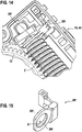
- third bearing element 20f is substantially analogous to the third bearing element 20d according to the 8 and 9 educated.
- it has a contact element 28f with a passage opening 61, wherein the passage opening 61 bounding wall simultaneously forms the contact surface 29f.
- the diameter of the passage opening 61 is particularly possible precisely to the outer diameter of the drive shaft 2 in the contact area of the contact surface 29f matched, such that between the through hole 61 and the circumference of the drive shaft 2, only a clearance fit is available, which allows easy mounting of the third bearing element 20f on the drive shaft 2.
- the contact surface 29f is always in abutting contact with the peripheral surface of the drive shaft 2.
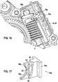
- third bearing element 20g corresponds approximately to the third bearing element 20a of FIGS. 2 and 3
- the abutment surface 29g of the contact element 28g is also formed with a radius, so that it partially abuts in the circumferential direction of the drive shaft 2 in this area.
- a lower and an upper portion of the abutment member 28g is connected to the bearing portion 35g via elastic intermediate members 62, 63.
- the contact surface 29g facing away from the rear side 64 of the contact element 28g is spaced from a stop surface 65 of the bearing portion 35g, wherein the back 64 abuts at a large deflection of the drive shaft 2 on the stop surface 65.
- Last is in the Fig. 18 a third bearing element 20h shown, which is arranged in a slot-shaped receptacle 66 of the transmission housing 10. It is essential that the third bearing element 20h consists of a rubber-elastic material.
- the third bearing element 20h has a contact surface 29h provided with a radius, which abuts in regions on the circumferential surface of the drive shaft 2. The area of the contact surface 29h simultaneously forms the abutment element 28h, while the region of the third bearing element 20h, which is located within the receptacle 66, forms the bearing section 35h.
- the material of the third bearing element 20h located between the abutment surface 29h and the receptacle 66 at the same time forms the elastic intermediate element 67, the abutment surface 29h always abutting (in regions) on the circumferential surface of the drive shaft 2.
- the drive unit 100 equipped with the third bearing element 20, 20a to 20h can be modified or modified in many ways without deviating from the idea of the invention.
Landscapes
- Engineering & Computer Science (AREA)
- General Engineering & Computer Science (AREA)
- Mechanical Engineering (AREA)
- Power Engineering (AREA)
- Gear Transmission (AREA)
- General Details Of Gearings (AREA)
- Seats For Vehicles (AREA)
- Chairs For Special Purposes, Such As Reclining Chairs (AREA)
- Support Of The Bearing (AREA)
Description
- Die Erfindung betrifft eine Antriebseinheit nach dem Oberbegriff des Anspruchs 1.
- Eine derartige Antriebseinheit ist aus der
DE 10 2010 064 295 A1 der Anmelderin bekannt. Die bekannte Antriebseinheit ist Bestandteil eines Komfortantriebs in einem Kraftfahrzeug, wie beispielsweise einem Fensterheberantrieb, einem Schiebedachantrieb, einem Sitzverstellungsantrieb. Insbesondere weist die bekannte Antriebseinheit beidseitig eines Antriebsmotors ein erstes und ein zweites Lagerelement zur Lagerung einer Antriebswelle auf. Die Antriebswelle wirkt mit einer Schneckenverzahnung mit einer Gegenverzahnung eines als Stirnrad ausgebildeten Getrieberads zusammen. Auf der dem Antriebsmotor abgewandten Seite des Getrieberads ist ein drittes Lagerelement vorgesehen, das dazu dient, quer zur Längsachse der Antriebswelle wirkende Kräfte, die zu einer Auslenkung der Antriebswelle führen, aufzunehmen bzw. abzustützen. Hierzu weist die bekannte Antriebseinheit bzw. deren drittes Lagerelement einen die Antriebswelle an ihrem Umfang vorzugsweise mit radialem Spiel umgreifenden Abschnitt auf, der über einen flexiblen Zwischenabschnitt mit einem in einer Aufnahme eines Getriebegehäuses angeordneten Lagerbereich verbunden ist. Insgesamt gesehen ist das einteilige dritte Lagerelement hülsenförmig ausgebildet mit einer Durchgangsöffnung zur Aufnahme des Endbereichs der Antriebswelle. Nachteilig bei der aus der genannten Schrift bekannten Antriebseinheit ist es, dass das dritte Lagerelement zu dessen Lagerung einen relativ großen Raumbedarf in dem Getriebegehäuse benötigt, da das dritte Lagerelement über dessen gesamten Umfang gesehen in einer entsprechenden Aufnahme des Getriebegehäuses angeordnet ist. Darüber hinaus schränkt der benötigte Raum für die Aufnahme des dritten Lagerelements den Bauraum bzw. die Möglichkeit einer Axialabstützung für den Endbereich der Antriebswelle ein oder macht eine derartige Axialabstützung nicht mehr möglich. Als besonders nachteilhaft ist darüber hinaus anzusehen, dass es bei einem radialen Spiel zwischen dem Umfang der Antriebswelle und dem dritten Lagerelement typischerweise aufgrund von Bauteiletoleranzen zu einem periodischen Berühren bzw. Anschlagen der Umfangsfläche der Antriebswelle an dem dritten Lagerelement kommt, was als störendes Geräusch wahrgenommen werden kann. - Mit der
US 3 960 194 A ist ein Schneckengetriebe bekannt geworden, bei dem die Schneckenwelle mittels eines federbeaufschlagten Keilelements gegen das Schneckenrad gepresst wird. - Die
DE 10 2007 047369 A1 zeigt ein Schneckengetriebe eines Lenksystems, bei dem ein Kugellager, in dem die Schneckenwelle gelagert ist, gegen das Schneckenrad gedrückt wird. Dies wird mit Hilfe eines beweglich gelagerten Druckstücks durchgeführt, das mittels eine s Federelements verspannt ist. - Ausgehend von dem dargestellten Stand der Technik liegt der Erfindung die Aufgabe zugrunde, eine Antriebseinheit nach dem Oberbegriff des Anspruchs 1 derart weiterzubilden, dass diese einerseits einen möglichst geringen Raumbedarf für die Aufnahme des dritten Lagerelements in dem Getriebegehäuse benötigt, und andererseits eine reduzierte Geräuschemission sowie zusätzlich eine möglichst einfache Anordnung einer Einrichtung zur Axialabstützung der Antriebswelle ermöglicht. Diese Aufgabe wird erfindungsgemäß bei einer Antriebseinheit mit den Merkmalen des Anspruchs 1 dadurch gelöst, dass die Aufnahme für das dritte Lagerelement, das der seitlichen Abstützung der Antriebswelle dient, im Getriebegehäuse in Bezug zur Antriebswelle seitlich neben der Antriebswelle in einem Teilbereich in Umfangsrichtung der Antriebswelle angeordnet ist, und dass das dritte Lagerelement ein Anlageelement aufweist, das in ständigem Anlagekontakt zur Antriebswelle angeordnet ist.
- Mit anderen Worten gesagt bedeutet dies, dass durch die spezielle Ausbildung des dritten Lagerelements dieses lediglich an einem einzigen seitlichen Bereich in einer Aufnahme des Getriebegehäuses angeordnet sein muss, so dass es im Gegensatz zum Stand der Technik nicht mehr erforderlich ist, in dem Getriebegehäuse eine in Bezug auf die Antriebswelle in Umfangsrichtung vollständig umlaufende Aufnahme für das dritte Lagerelement auszubilden. Dadurch wird insbesondere zusätzlicher Einbauraum für eine Axialabstützung für die Antriebswelle geschaffen. Darüber hinaus ist durch die ständige Anlage des dritten Lagerelements an der Antriebswelle sichergestellt, dass keine Geräusche aufgrund eines lediglich zeitweisen Anliegens bzw. Kontaktieren der Antriebswelle an dem dritten Lagerelement entstehen können.
- Vorteilhafte Weiterbildungen der erfindungsgemäßen Antriebseinheit sind in den Unteransprüchen aufgeführt.
- In einer ersten konstruktiven Ausgestaltung des in Wirkverbindung mit der Antriebswelle angeordneten Anlageelements des dritten Lagerelements ist es vorgesehen, dass das Anlageelement auf der der Antriebswelle zugewandten Seite eine ebene Anlagefläche aufweist, derart, dass die Anlagefläche in Richtung der Längsachse der Antriebswelle linienförmig an der Antriebswelle anliegt. Eine derartige Ausbildung der Anlagefläche des dritten Lagerelements ermöglicht es beispielsweise, das dritte Lagerelement erst nach der Montage der Antriebswelle in das Getriebegehäuse einzusetzen, so dass sich eine größere Flexibilität hinsichtlich unterschiedlicher Montagemöglichkeiten der Antriebseinheit ergeben.
- Alternativ ist es jedoch auch möglich, dass das Anlageelement des dritten Lagerelements auf der der Antriebswelle zugewandten Seite eine konkav gewölbte bzw. mit einem Radius versehene Anlagefläche aufweist, derart, dass die Anlagefläche in Umfangsrichtung der Antriebswelle an der Antriebswelle anliegt. Eine derartige Ausbildung der Anlagefläche des dritten Lagerelements ermöglicht eine verbesserte bzw. vergrößerte Anlage der Antriebswelle an der Anlagefläche des dritten Lagerelements.
- Um sicherzustellen, dass das dritte Lagerelement mit seinem Anlageelement in ständigem Anlagekontakt zur Antriebswelle angeordnet ist, ist es vorgesehen, dass das Anlageelement durch wenigstens ein elastisches Zwischenelement mit einem Lagerabschnitt des dritten Lagerelements verbunden ist, dass der Lagerabschnitt in der Aufnahme des Getriebegehäuses form- oder klemmschlüssig angeordnet ist, und dass das Zwischenelement eine Anlagekraft auf das Anlageelement in Richtung der Antriebswelle erzeugt. Das dritte Lagerelement weist somit drei unterschiedliche Funktionsbereiche auf: Zum Einen das in ständigem Kontakt mit der Antriebswelle befindliche Anlageelement, zum Zweiten das Zwischenelement, das die benötigte Anlagekraft für das Anlageelement an die Antriebswelle erzeugt, und zum Dritten den
- Lagerabschnitt, der in der Aufnahme des Getriebegehäuses angeordnet ist. Diese konstruktive Aufteilung des dritten Lagerelements in drei Funktionsbereiche ermöglicht es, den jeweiligen Funktionsbereich optimal an seine jeweilige Aufgabe anzupassen.
- Um zu große Auslenkungen der Antriebswelle zu vermeiden, sodass Beschädigungen an der Antriebseinheit ausgeschlossen werden können, ist es vorgesehen, dass das Anlageelement mit einem Anschlag zusammenwirkt, der die Auslenkung des Anlageelements in einer Richtung senkrecht zur Längsachse der Antriebswelle begrenzt. Der Anschlag dient somit dem Schutz der Bestandteile der Antriebseinheit, so dass die Funktionalität der Antriebseinheit bis zur maximalen Auslenkung der Antriebswelle, bei der das Anlageelement mit dem Anschlag zusammenwirkt, sichergestellt ist.
- In einer ersten konstruktiven Ausgestaltung des Anschlags ist es vorgesehen, dass der Anschlag am dritten Lagerelement selbst ausgebildet ist. Alternativ ist es jedoch auch in einer zweiten konstruktiven Ausgestaltung denkbar, dass der Anschlag am Getriebegehäuse ausgebildet ist.
- Zur Erzeugung der benötigten Anlagekraft des Anlageelements an der Antriebswelle ist es in einer ersten konstruktiven Ausgestaltung vorgesehen, dass sich das wenigstens eine Zwischenelement im Wesentlichen in einer senkrecht zur Längsachse der Antriebswelle verlaufenden Richtung erstreckt. Eine derartige Anordnung bzw. Ausbildung des Zwischenelements hat insbesondere den Vorteil eines in Längsrichtung der Antriebswelle minimierten Bauraums für das dritte Lagerelement, was beispielsweise die Anordnung einer Einrichtung zur Aufnahme von Axialkräften der Antriebswelle erleichtert.
- Alternativ ist es jedoch auch denkbar, dass sich das wenigstens eine Zwischenelement im Wesentlichen in einer parallel zur Längsachse der Antriebswelle verlaufenden Richtung erstreckt. Eine derartige Anordnung bzw. Ausbildung des Zwischenelements hat den Vorteil einer verbesserten Federwirkung des Anlageelements, da sich dadurch, ohne den Bauraum des Getriebegehäuses in einer senkrecht zur Längsachse der Antriebswelle verlaufenden Richtung zu vergrößern, die Möglichkeit bietet, das Zwischenelement beispielsweise mit einer relativ großen Länge auszubilden. Um stets eine sichere Anlage des Anlageelements des dritten Lagerelements an der Antriebswelle für den gesamten Bereich der möglichen Auslenkung der Antriebswelle zu ermöglichen, ist es vorgesehen, dass das Getriebegehäuse durch Wandabschnitte gebildete Führungsbereiche für das Anlageelement aufweist, die sich senkrecht zur Längsachse der Antriebswelle erstrecken und unter Ausbildung einer Spielpassung mit Seitenwänden des Anlageelements zusammenwirken.
- In bevorzugter konstruktiver Ausgestaltung des das dritte Lagerelement aufnehmenden Getriebegehäuses ist es vorgesehen, dass das Getriebegehäuse ein vorzugsweise schalenförmig ausgebildetes Grundelement aufweist, in dem die Aufnahme für die Lagereinrichtung ausgebildet ist, und dass der Bereich der Aufnahme mittels eines mit dem Grundelement verbindbaren Deckelelements überdeckt ist, das an dem Lagerelement bereichsweise anliegt. Insbesondere erfolgt die Anlage des Deckelelements zumindest an dem Lagerabschnitt des dritten Lagerelements, um eine definierte Anordnung des Lagerabschnitts des dritten Lagerelements in dem Getriebegehäuse sicherzustellen.
- Besonders einfach und kostengünstig lässt sich das dritte Lagerelement herstellen, wenn dieses als einteiliges Kunststoffspritzgußteil ausgebildet ist. Alternativ ist es jedoch auch denkbar, dass das dritte Lagerelement einstückig ausgebildet ist und aus einem gummielastischen Material besteht.
- Bevorzugt ist eine Ausbildung der Antriebseinheit mit einer die Antriebswelle in Axialrichtung mit einer auf eine Stirnfläche der Antriebswelle wirkenden Abstützeinrichtung auszustatten, die die Antriebswelle in Richtung des Getriebeelements kraftbeaufschlagt.
- Bevorzugt findet eine erfindungsgemäße Antriebseinheit Verwendung in einem Komfortantrieb in einem Kraftfahrzeug, wie einem Fensterheberantrieb, einem Schiebedachantrieb, einem Sitzverstellungsantrieb o.ä. Ein derartiger Komfortantrieb weist insbesondere den Vorteil geringer Geräuschemissionen und eines besonders kompakten Aufbaus auf.
- Weitere Vorteile, Merkmale und Einzelheiten der Erfindung ergeben sich aus der nachfolgenden Beschreibung bevorzugter Ausführungsbeispiele sowie anhand der Zeichnung.
- Diese zeigt in:
- Fig. 1
- eine erfindungsgemäße Antriebseinheit in einer vereinfachten, teilweise geschnittenen Seitenansicht,
- Fig. 2
- einen Teilbereich der Antriebseinheit gemäß
Fig. 1 bei einer ersten Ausführungsform einer erfindungsgemäßen Lagereinrichtung in perspektivischer Ansicht, - Fig. 3
- ein bei der Antriebseinheit gemäß
Fig. 2 verwendetes drittes Lagerelement in perspektivischer Einzeldarstellung, - Fig. 4
- einen bei der Antriebseinheit gemäß
Fig. 2 verwendeten Getriebedeckel in perspektivischer Darstellung, - Fig. 5
- eine zweite Ausführungsform einer erfindungsgemäßen Lagereinrichtung in einem Getriebegehäuse in perspektivischer Darstellung,
- Fig. 6
- ein drittes Lagerelement der Lagereinrichtung gemäß
Fig. 5 in perspektivischer Einzeldarstellung, - Fig. 7
- eine dritte Ausführungsform einer erfindungsgemäßen Lagereinrichtung im Getriebegehäuse in perspektivischer Darstellung,
- Fig. 8
- eine vierte erfindungsgemäße Lagereinrichtung im Einbauzustand im Getriebegehäuse in perspektivischer Darstellung,
- Fig. 9
- das dritte Lagerelement, wie es in der Lagereinrichtung der
Fig. 8 verwendet wird, in perspektivischer Einzeldarstellung, - Fig. 10
- eine fünfte Ausführungsform einer erfindungsgemäßen Lagereinrichtung im Einbauzustand in einem Getriebegehäuse in perspektivischer Darstellung,
- Fig. 11
- den Einbauort des dritten Lagerelements in der Antriebseinheit gemäß
Fig. 10 in vergrößerter, perspektivischer Einzeldarstellung, - Fig. 12
- eine sechste erfindungsgemäße Lagereinrichtung in einem Getriebegehäuse in perspektivischer Darstellung,
- Fig. 13
- ein in der
Fig. 12 vorgesehenes drittes Lagerelement in perspektivischer Einzeldarstellung, - Fig. 14
- eine siebte Ausführungsform einer erfindungsgemäßen Lagereinrichtung in einem Getriebegehäuse in perspektivischer Darstellung,
- Fig. 15
- ein drittes Lagerelement wie es in der Lagereinrichtung gemäß der
Fig. 14 verwendet wird, in perspektivischer Einzeldarstellung, - Fig. 16
- eine achte erfindungsgemäße Ausbildung einer Lagereinrichtung in einem Getriebegehäuse in perspektivischer Darstellung,
- Fig. 17
- ein drittes Lagerelement, wie es in der
Fig. 16 verwendet wird, in perspektivischer Einzeldarstellung und - Fig. 18
- eine neunte erfindungsgemäße Lagereinrichtung unter Verwendung eines aus einem gummielastischen Material bestehenden dritten Lagerelements in einem Getriebegehäuse in perspektivischer Darstellung.
- Gleiche Elemente bzw. Elemente mit gleicher Funktion sind in den Figuren mit den gleichen Bezugsziffern versehen.
- In der
Fig. 1 ist der grundsätzliche Aufbau einer erfindungsgemäßen Antriebseinheit 100 in stark vereinfachter Form dargestellt, wie sie als Bestandteil eines Komfortantriebs in einem Kraftfahrzeug dient. Unter einem Komfortantrieb wird dabei im Rahmen der Erfindung beispielhaft, und nicht einschränkend, ein Fensterheberantrieb, ein Schiebedachantrieb, ein Sitzverstellungsantrieb o.ä. verstanden. - Die Antriebseinheit 100 weist einen als Elektromotor ausgebildeten Antriebsmotor 1 auf, der eine aus dem Gehäuse des Antriebsmotors 1 herausragende Antriebswelle 2 hat. Die Antriebswelle 2 des Antriebsmotors 1 ist beidseitig des Antriebsmotors 1 in einem vorzugsweise als Kugellager oder Gleitlager ausgebildeten ersten und zweiten Lagerelement 3, 4 gelagert. In dem in der
Fig. 1 dargestellten Ausführungsbeispiel sind die beiden Lagerelemente 3, 4 in jeweils einer Aufnahme 5, 6 in einem in derFig. 1 lediglich bereichsweise dargestellten Getriebegehäuse 10 aufgenommen bzw. angeordnet. Es ist jedoch selbstverständlich auch möglich, in Abänderung der Darstellung derFig. 1 den Antriebsmotor 1 an ein entsprechendes Getriebegehäuse 10 mit einer Stirnseite des Antriebsmotors 1 anzuflanschen, wobei die beiden Lagerelemente 3, 4 dann zum Beispiel in einem Motorgehäuse des Antriebsmotors 1 angeordnet sind. - Auf der dem ersten Lagerelement 3 abgewandten Seite des zweiten Lagerelements 4 weist die Antriebswelle 2 einen Abschnitt mit einer Verzahnung 11 in Form einer Schneckenverzahnung auf. Die Verzahnung 11 wirkt mit einer Gegenverzahnung 12 eines ausschnittsweise dargestellten Getriebeeinrichtung in Form eines Getrieberads 13 zusammen, das in Form eines Stirnrads ausgebildet ist, und das aus Kunststoff besteht. Das Getrieberad 13 dient der Übertragung eines von dem Antriebsmotor 1 erzeugten Drehmoments auf ein nicht dargestelltes, zu verstellendes Element, beispielsweise einer Fensterscheibe oder einem Schiebedach.
- Der dem Antriebsmotor 1 abgewandte Endbereich 15 der Antriebswelle 2 wirkt mit einem dritten Lagerelement 20 als Abstützelement zusammen, das dazu ausgebildet ist, die Auslenkung des Endbereichs 15 der Antriebswelle 1 in einer senkrecht zur Längsachse 21 der Antriebswelle 2 verlaufenden, von dem Getrieberad 13 wegweisenden Richtung, verursacht durch eine Kraft F zwischen der Verzahnung 11 und der Gegenverzahnung 12, zu begrenzen. Die der Lagerung der Antriebswelle 2 dienende Lagereinrichtung 50 der Antriebseinheit 100 weist somit die drei Lagerelemente 3, 4 und 20 auf. Weiterhin wirkt der Endbereich 15 der Antriebswelle 2 mit einer Abstützeinrichtung 22 zusammen, die in Richtung der Längsachse 21 auf die Abstützeinrichtung 22 wirkende Längskräfte aufnimmt bzw. abstützt. Hierzu weist die Abstützeinrichtung 22, wie insbesondere anhand der Darstellung der
Fig. 2 erkennbar ist, eine vorzugsweise aus Metall bestehende Abstützplatte 23 auf, die über ein elastisches Element 24 in Form beispielsweise eines zylindrischen Gummielements die Antriebswelle 2 in Axialrichtung abstützt, wobei die Abstützplatte 23 in Anlagekontakt mit dem vorzugsweise ballig ausgebildeten Wellenende 25 angeordnet ist. Die Abstützeinrichtung 22 ist in einem Aufnahmeraum 26 des Getriebegehäuses 10 angeordnet. - In den
Fig. 2 und 3 ist das dritte Lagerelement 20 der Lagereinrichtung 50 in einer ersten Ausführungsform der Erfindung näher dargestellt. Insbesondere erkennt man, dass das aus Kunststoff bestehende, einstückig ausgebildete und im Spritzgussverfahren hergestellte dritte Lagerelement 20 im Wesentlichen aus drei Bereichen besteht: Der erste Bereich ist gebildet durch ein blockförmiges Anlageelement 28, das auf der der Antriebswelle 2 zugewandten Seite eine ebene Anlagefläche 29 aufweist. Das Anlageelement 28 ist über zwei parallel zueinander angeordnete, in Richtung des Doppelpfeils 31 elastisch verformbare Zwischenelemente 32, 33 mit einem Lagerabschnitt 35 verbunden. Der im Wesentlichen plattenförmig ausgebildete Lagerabschnitt 35 weist senkrecht zu einer Rückseite 36 ein stegförmig ausgebildetes Anschlagelement 37 auf, das die Auslenkung des Anlageelements 28 in Richtung zum Lagerabschnitt 35 hin, d.h. senkrecht zur Längsachse 21 der Antriebswelle 2, begrenzt, wobei das Anschlagelement 37 fluchtend zum Anlageelement 28 angeordnet ist. - Der Lagerabschnitt 35 ist in einer Aufnahme 38 des Getriebegehäuses 10 seitlich neben der Antriebswelle 2 über einen Teilbereich der Antriebswelle 2 in deren Umfangsrichtung betrachtet zumindest bereichsweise form- bzw. klemmschlüssig aufgenommen. Demgegenüber sind die beiden Zwischenelemente 32, 33 mit Spiel in der Aufnahme 38 angeordnet, um eine Deformation der Zwischenelemente 32, 33 zu ermöglichen. Die Aufnahme 38 weist als Führungsbereiche dienende Wandabschnitte 39, 40 auf, die über eine Spielpassung mit Seitenwänden 41, 42 des Anlageelements 28 zusammenwirken, und die bei einer Auslenkung des Anlageelements 28 in Richtung des Anschlagelements 37 eine Führung des Anlageelements 28 in einer senkrecht zur Längsachse 21 der Antriebswelle 2 verlaufenden Richtung bewirken.
- Wesentlich für das Anlageelement 28 ist, dass die Anordnung des dritten Lagerelements 20 in der Aufnahme 38 derart ist, dass über die beiden Zwischenelemente 32, 33 das Anlageelement 28 mit einer Anlagekraft auf den Umfang der Antriebswelle 2 beaufschlagt wird, sodass das Anlageelement 28 mit seiner Anlagefläche 29 stets in Anlagekontakt mit der Umfangsfläche der Antriebswelle 2 angeordnet ist. Der Kontakt erfolgt dabei parallel zur Längsachse 21 der Antriebswelle 2 linienförmig über die Breite der Anlagefläche 29.
- Die Aufnahme 38 für das dritte Lagerelement 20 ist in einem vorzugsweise schalenförmig ausgebildeten Grundelement 43 des ebenfalls vorzugsweise im Kunststoffspritzgussverfahren hergestellten Getriebegehäuses 10 ausgebildet. Um im Einbauzustand des dritten Lagerelements 20 das dritte Lagerelement 20 in der Aufnahme 38 zu positionieren bzw. zu sichern, ist das Grundelement 43 zumindest im Bereich des dritten Lagerelements 20 von einem in der
Fig. 4 erkennbaren Deckelelement 44 überdeckt. Das Deckelelement 44 weist einen leistenförmigen Abstützkörper 45 auf, der im montierten Zustand des Getriebegehäuses 10 mit dem Grundelement 43 an der Oberseite des Lagerabschnitts 35 anliegt und diesen somit in der Aufnahme 38 positioniert bzw. fixiert. - In den
Fig. 5 und 6 ist ein modifiziertes drittes Lagerelement 20a dargestellt, das sich von dem Lagerelement 20 dadurch unterscheidet, dass das Anlageelement 28a und der Lagerabschnitt 35a über ein einziges Zwischenelement 46 verbunden sind. Im Unterschied zu den beiden Zwischenelementen 32, 33 des dritten Lagerelements 20 erstreckt sich das Zwischenelement 46 im Einbauzustand im Getriebegehäuse 10 im Wesentlichen in einer parallel zur Längsachse 21 der Antriebswelle 2 verlaufenden Richtung, sodass auch die Aufnahme 38a in dem Getriebegehäuse 10 sich im Wesentlichen (im Gegensatz zur Aufnahme 38 für das dritte Lagerelement 20) parallel zur Längsachse 21 der Antriebswelle 2 erstreckt. Hierbei verläuft ein Teil der Aufnahme 38 seitlich neben der Abstützeinrichtung 22. Auch das Anlageelement 28a weist eine ebene Anlagefläche 29a zur Anlage an der Umfangfläche der Antriebswelle 2 auf und ist durch das Zwischenelement 46 derart in Richtung der Antriebswelle 2 kraftbeaufschlagt, dass eine ständige Anlage der Anlagefläche 29a an der Antriebswelle 2 ermöglicht wird. Das Anlageelement 28a weist auf der der Anlagefläche 29a abgewandten Seite eine ebene Rückseite 47 auf, die mit einer durch einen Teilbereich der Aufnahme 38a ausgebildeten Anschlagfläche 48 zusammenwirkt, um die Bewegung des Anlageelements 28a bei einer Auslenkung der Antriebswelle 2 zu begrenzen. - Das dritte Lagerelement 20b der
Fig. 7 ist zumindest im Wesentlichen identisch zum dritten Lagerelement 20a entsprechend denFig. 5 und 6 ausgebildet. Unterschiede ergeben sich lediglich in der (seitlichen) Führung der Anlageelemente 28a, 28b. Während bei dem Anlageelement 28a entsprechend derFig. 5 das Anlageelement 28a im Bereich eines relativ schmal ausgebildeten, stegförmigen Bereichs 49 an Wandabschnitten 39a, 40a der Aufnahme 38a erfolgt, erfolgt die Führung des Anlageelements 28b über einen in senkrechter Richtung zur Längsachse 21 verlaufenden vergrößerten Bereich des Anlageelements 28b. Hierzu ist beispielsweise die eine Seitenfläche 51 des Anlageelements 28b verlängert ausgebildet und reicht sowohl über den Bereich 49, als auch über einen gegenüber dem Bereich 49 verbreitert ausgebildeten Bereich 52. Die Seitenfläche 51 wirkt mit einem gegenüber dem Wandabschnitt 40a verbreiterten Wandabschnitt 40b zusammen. - In den
Fig. 8 und 9 ist ein drittes Lagerelement 20c dargestellt, das sich von dem Lagerelement 20a bzw. 20b im Wesentlichen dadurch unterscheidet, dass das Anlageelement 28c eine konkav ausgebildete bzw. mit einem Radius R versehene Anlagefläche 29c aufweist, die bereichsweise in Umfangsrichtung an der Antriebswelle 2 anliegt, beispielsweise über einen Winkelbereich von ca. 150°. Die Anlagefläche 29c umgreift somit die Umfangsfläche der Antriebswelle 2 bereichsweise formschlüssig und sichert bzw. stützt somit die Antriebswelle 2 auch in einer senkrecht zur Auslenkung der Antriebswelle 2 verlaufenden Richtung bei einer Auslenkung der Antriebswelle 2. Gegenüber den ebenen Anlageflächen 29, 29a liegt die Anlagefläche 29c somit über einen größeren Bereich an der Umfangsfläche der Antriebswelle 2 an. - Das in den
Fig. 10 und 11 dargestellte dritte Lagerelement 20d ist im Wesentlichen blockförmig ausgebildet. Es kann entweder einstückig an dem Getriebegehäuse 10 angeformt sein, wenn das Getriebegehäuse 10 aus einem geeigneten Werkstoff besteht, oder aber als separates Bauteil ausgebildet sein. In diesem Fall ist es ebenfalls in einer entsprechenden Aufnahme des Getriebegehäuses 10 angeordnet. Das dritte Lagerelement 20d weist zwei miteinander zusammenwirkende, jeweils blockförmige Abschnitte in Form eines Anlageelements 28d und eines Lagerabschnitts 35d auf, die über ein stegartig ausgebildetes, elastisches Zwischenelement 53 einstückig miteinander verbunden sind. Zwischen dem Anlageelement 28d und dem Lagerabschnitt 35d ist ein Federspalt 54 ausgebildet, der eine Bewegung des Anlageelements 28d in Richtung des Pfeils 55 ermöglicht, bis das Anlageelement 28d an dem Lagerabschnitt 35d anliegt. Die dem Lagerabschnitt 35d abgewandte Anlagefläche 29d des Anlageelements 28d ist ebenfalls eben ausgebildet, wobei das Anlageelement 28d unter Vorspannung stets an der Umfangsfläche der Antriebswelle 2 anliegt. - Das in den
Fig. 12 und 13 dargestellte dritte Lagerelement 20e erstreckt sich mit seinem Lagerabschnitt 35e ebenfalls im Wesentlichen parallel zur Längsachse 21 der Antriebswelle 2 neben der Antriebswelle 2. Der Lagerabschnitt 35e weist zwei zapfenförmige Fortsätze 56, 57 auf, die in entsprechende Öffnungen bzw. Löcher im Getriebegehäuse 10 verankerbar sind. Der Lagerabschnitt 35e ist über ein zylindrisches Zwischenelement 58 mit dem Anlageelement 28e verbunden. Das Anlageelement 28e weist wiederum eine ebene Anlagefläche 29e zur ständigen Anlage an der Umfangsfläche der Antriebswelle 2 auf. Wesentlich ist, dass das dritte Lagerelement 20e in Form einer Torsionsfeder ausgebildet ist, bei der bei einer Auslenkung des Anlageelements 28e dieses um eine Längsachse 59 des Zwischenelements 58 in Richtung des Pfeils 60 geschwenkt wird. Auch hier ist durch eine entsprechende Formgebung bzw. Auslegung des dritten Lagerelements 20e eine ständige Anlage der Anlagefläche 29e an der Antriebswelle 2 gewährleistet. - Das in den
Fig. 14 und 15 dargestellte dritte Lagerelement 20f ist im Wesentlichen in Analogie zu dem dritten Lagerelement 20d entsprechend denFig. 8 und 9 ausgebildet. Im Unterschied hierzu weist es ein Anlageelement 28f mit einer Durchgangsöffnung 61 auf, wobei die die Durchgangsöffnung 61 begrenzende Wand gleichzeitig die Anlagefläche 29f ausbildet. Der Durchmesser der Durchgangsöffnung 61 ist insbesondere möglicht genau auf den Außendurchmesser der Antriebswelle 2 im Anlagebereich der Anlagefläche 29f abgestimmt, derart, dass zwischen der Durchgangsöffnung 61 und dem Umfang der Antriebswelle 2 lediglich eine Spielpassung vorhanden ist, die eine problemlose Montage des dritten Lagerelements 20f auf der Antriebswelle 2 ermöglicht. Durch eine entsprechende Anordnung des dritten Lagerelements 20f ist auch hier sichergestellt, dass die Anlagefläche 29f sich stets in Anlagekontakt mit der Umfangsfläche der Antriebswelle 2 befindet. - Das in den
Fig. 16 und 17 dargestellte dritte Lagerelement 20g entspricht in etwa dem dritten Lagerelement 20a derFig. 2 und 3 . Im Unterschied hierzu ist jedoch die Anlagefläche 29g des Anlageelements 28g ebenfalls mit einem Radius ausgebildet, sodass es bereichsweise in Umfangsrichtung der Antriebswelle 2 bereichsweise an dieser anliegt. Ein unterer und ein oberer Bereich des Anlageelements 28g ist über elastische Zwischenelemente 62, 63 mit dem Lagerabschnitt 35g verbunden. Die der Anlagefläche 29g abgewandte Rückseite 64 des Anlageelements 28g ist beabstandet zu einer Anschlagfläche 65 des Lagerabschnitts 35g angeordnet, wobei die Rückseite 64 bei einer zu großen Auslenkung der Antriebswelle 2 an der Anschlagfläche 65 anliegt. - Zuletzt ist in der
Fig. 18 ein drittes Lagerelement 20h dargestellt, welches in einer schlitzförmigen Aufnahme 66 des Getriebegehäuses 10 angeordnet ist. Wesentlich dabei ist, dass das dritte Lagerelement 20h aus einem gummielastischen Werkstoff besteht. Das dritte Lagerelement 20h weist eine mit einem Radius versehene Anlagefläche 29h auf, die bereichsweise an der Umfangsfläche der Antriebswelle 2 anliegt. Der Bereich der Anlagefläche 29h bildet gleichzeitig das Anlageelement 28h auf, während der Bereich des dritten Lagerelements 20h, der sich innerhalb der Aufnahme 66 befindet, den Lagerabschnitt 35h ausbildet. Das zwischen der Anlagefläche 29h und der Aufnahme 66 befindliche Material des dritten Lagerelements 20h bildet gleichzeitig das elastische Zwischenelement 67 aus, wobei die Anlagefläche 29h stets (bereichsweise) an der Umfangsfläche der Antriebswelle 2 anliegt. - Das mit dem dritten Lagerelement 20, 20a bis 20h ausgestattete Antriebseinheit 100 kann in vielfältiger Art und Weise abgewandelt bzw. modifiziert werden, ohne vom Erfindungsgedanken abzuweichen.
Claims (15)
- Antriebseinheit (100) mit einem Antriebsmotor (1), einer Lagereinrichtung (50), einem Getriebegehäuse (10) und einem Getriebeelement (13), wobei der Antriebsmotor (1) über eine mehrfach gelagerte Antriebswelle (2) mit dem Getriebeelement (13) zusammenwirkt, wobei die Antriebswelle (2) ein erstes Lagerelement (3), das auf der dem Getriebeelement (13) gegenüberliegenden Seite des Antriebsmotors (1) angeordnet ist, ein zweites Lagerelement (4), das zwischen dem Antriebsmotor (1) und dem Getriebeelement (13) angeordnet ist und ein drittes Lagerelement (20; 20a bis 20h), das auf der dem Antriebsmotor (1) abgewandten Seite des Getriebeelements (13) angeordnet ist, aufweist, wobei das dritte Lagerelement (20; 20a bis 20h) in einer Richtung senkrecht zur Längsachse (21) der Antriebswelle (2) beweglich angeordnet ist, und wobei das dritte Lagerelement (20; 20a bis 20h) in einer Aufnahme (38; 38a; 66) des Getriebegehäuses (10) aufgenommen ist, wobei die Aufnahme (38; 38a; 66) für das dritte Lagerelement (20; 20a bis 20h) im Getriebegehäuse (10) in Bezug zur Antriebwelle (2) seitlich neben der Antriebswelle (2) in einem Teilbereich in Umfangsrichtung der Antriebswelle (2) angeordnet ist, und wobei das dritte Lagerelement (20; 20a bis 20h) ein Anlageelement (28; 28a bis 28h) aufweist, das in ständigem Anlagekontakt zur Antriebswelle (2) angeordnet ist, dadurch gekennzeichnet, dass das Anlageelement (28; 28a; 28b; 28d; 28e) mit einem Anschlag (37; 48; 65) zusammenwirkt, der die Auslenkung des Anlageelements (28; 28a; 28b; 28d; 28e) in einer senkrecht zur Längsachse (21) der der Antriebswelle (2) verlaufenden Richtung begrenzt.
- Antriebseinheit nach Anspruch 1,
dadurch gekennzeichnet,
dass das Anlageelement (28; 28a; 28b; 28d; 28e) auf der der Antriebswelle (2) zugewandten Seite eine ebene Anlagefläche (29; 29a; 29b; 29d; 29e) aufweist, derart, dass die Anlagefläche (29; 29a; 29b; 29d; 29e) in Richtung der Längsachse (21) der Antriebswelle (2) linienförmig an der Antriebswelle (2) anliegt. - Antriebseinheit nach Anspruch 1,
dadurch gekennzeichnet,
dass das Anlageelement (28c; 28f; 28g; 28h) auf der der Antriebswelle (2) zugewandten Seite eine konkav gewölbte bzw. mit einem Radius (R) versehene Anlagefläche (29c; 29f; 29g; 29h) aufweist, derart, dass die Anlagefläche (29c; 29f; 29g; 29h) in Umfangsrichtung der Antriebswelle (2) an der Antriebswelle (2) anliegt. - Antriebseinheit nach einem der Ansprüche 1 bis 3,
dadurch gekennzeichnet,
dass das Anlageelement (28; 28a; 28b; 28d; 28e) durch wenigstens ein elastisches Zwischenelement (32, 33; 46; 53; 58; 62, 63; 67) mit einem Lagerabschnitt (35; 35a; 35d; 35e; 35g; 35h) des dritten Lagerelements (20; 20a bis 20h) verbunden ist, dass der Lagerabschnitt (35; 35a; 35d; 35e; 35g; 35h) in der Aufnahme (38; 38a; 66) des Getriebegehäuses (10) klemm- oder formschlüssig angeordnet ist, und dass das wenigstens eine Zwischenelement (32, 33; 46; 53; 58; 62, 63) eine Anlagekraft auf das Anlageelement (28; 28a; 28b; 28d; 28e) in Richtung der Antriebswelle (2) erzeugt. - Antriebseinheit nach einem der Ansprüche 1 bis 4,
dadurch gekennzeichnet,
dass
das Abstützelement dazu ausgebildet ist, die Auslenkung des Endbereichs (15) der Antriebswelle (1) in einer senkrecht zur Längsachse (21) der Antriebswelle (2) verlaufenden, von dem Getrieberad (13) wegweisenden Richtung, verursacht durch eine Kraft F zwischen der Verzahnung (11) und der Gegenverzahnung (12), zu begrenzen. - Antriebseinheit nach Anspruch 1,
dadurch gekennzeichnet,
dass der Anschlag (37; 65) am dritten Lagerelement (20; 20d; 20g; 20h) ausgebildet ist. - Antriebseinheit nach Anspruch 1,
dadurch gekennzeichnet,
dass der Anschlag (48) am Getriebegehäuse (10) ausgebildet ist. - Antriebseinheit nach einem der Ansprüche 4 bis 7,
dadurch gekennzeichnet,
dass sich das Zwischenelement (32, 33; 53; 62, 63; 67) im Wesentlichen in einer senkrecht zur Längsachse (21) der Antriebswelle (2) verlaufenden Richtung erstreckt. - Antriebseinheit nach einem der Ansprüche 4 bis 7,
dadurch gekennzeichnet,
dass sich das Zwischenelement (46; 58) im Wesentlichen in einer parallel zur Längsachse (21) der Antriebswelle (2) verlaufenden Richtung erstreckt. - Antriebseinheit nach einem der Ansprüche 1 bis 9,
dadurch gekennzeichnet,
dass das Getriebegehäuse (10) durch Wandabschnitte (39; 39a, 40; 40a; 40b) gebildete Führungsbereiche für das Anlageelement (28; 28a; 28b; 28c; 28f; 28g) aufweist, die sich senkrecht zur Längsachse (21) der Antriebswelle (2) erstrecken und unter Ausbildung einer Spielpassung mit Seitenwänden (41, 42; 51) des Anlageelements (28; 28a; 28b; 28c; 28f; 28g) zusammenwirken. - Antriebseinheit nach einem der Ansprüche 1 bis 10,
dadurch gekennzeichnet,
dass das Getriebegehäuse (10) ein vorzugsweise schalenförmig ausgebildetes Grundelement (43) aufweist, in dem die Aufnahme (38; 38a; 66) für die Lagereinrichtung (50) ausgebildet ist, und dass der Bereich der Aufnahme (38; 38a; 66) mittels eines mit dem Grundelement (43) verbindbaren Deckelelements (44) überdeckt ist, das an dem dritten Lagerelement (20; 20a bis 20h) bereichsweise anliegt. - Antriebseinheit nach einem der Ansprüche 1 bis 11,
dadurch gekennzeichnet,
dass das dritte Lagerelement (20; 20a bis 20h) als einteiliges Kunststoffspritzgußteil ausgebildet ist. - Antriebseinheit nach einem der Ansprüche 1 bis 11,
dadurch gekennzeichnet,
dass die dritte Lagereinrichtung (20h) einstückig ausgebildet ist und aus einem gummielastischen Material besteht. - Antriebseinheit nach einem der Ansprüche 1 bis 13
dadurch gekennzeichnet,
dass die Antriebswelle (2) in Axialrichtung mit einer auf eine Stirnfläche der Antriebswelle (2) wirkende Abstützeinrichtung (22) in Richtung des Getriebeelements (13) kraftbeaufschlagt ist. - Komfortantrieb in einem Kraftfahrzeug, wie Fensterheberantrieb, Schiebedachantrieb, Sitzverstellungsantrieb o.ä. mit einer Antriebseinheit (100) nach einem der Ansprüche 1 bis 14.
Applications Claiming Priority (2)
| Application Number | Priority Date | Filing Date | Title |
|---|---|---|---|
| DE102014212133.7A DE102014212133A1 (de) | 2014-06-25 | 2014-06-25 | Antriebseinheit |
| PCT/EP2015/064032 WO2015197573A1 (de) | 2014-06-25 | 2015-06-23 | Antriebseinheit |
Publications (2)
| Publication Number | Publication Date |
|---|---|
| EP3161946A1 EP3161946A1 (de) | 2017-05-03 |
| EP3161946B1 true EP3161946B1 (de) | 2019-10-09 |
Family
ID=53476891
Family Applications (1)
| Application Number | Title | Priority Date | Filing Date |
|---|---|---|---|
| EP15730789.3A Active EP3161946B1 (de) | 2014-06-25 | 2015-06-23 | Antriebseinheit |
Country Status (6)
| Country | Link |
|---|---|
| US (1) | US10578203B2 (de) |
| EP (1) | EP3161946B1 (de) |
| KR (1) | KR20170023852A (de) |
| CN (1) | CN106464083B (de) |
| DE (1) | DE102014212133A1 (de) |
| WO (1) | WO2015197573A1 (de) |
Families Citing this family (12)
| Publication number | Priority date | Publication date | Assignee | Title |
|---|---|---|---|---|
| JP6080066B1 (ja) * | 2016-03-07 | 2017-02-15 | パナソニックIpマネジメント株式会社 | パンチルト駆動装置及びカメラ装置 |
| DE102016214041B4 (de) * | 2016-07-29 | 2022-11-10 | Brose Fahrzeugteile Se & Co. Kommanditgesellschaft, Bamberg | Kraftfahrzeug-Stellantrieb |
| GB201616486D0 (en) * | 2016-09-28 | 2016-11-09 | Trw Limited | A gearbox assembly for an electric power steering apparatus |
| DE102016012032B4 (de) | 2016-10-11 | 2026-03-05 | Grammer Aktiengesellschaft | Gehäuse für einen elektrischen Antrieb |
| DE102017123210A1 (de) * | 2017-10-06 | 2019-04-11 | Kiekert Ag | Elektromotorischer Antrieb für kraftfahrzeugtechnische Anwendungen |
| DE102018112703A1 (de) * | 2018-05-28 | 2019-11-28 | Huf Hülsbeck & Fürst GmbH & Co KG | Kraftfahrzeug-Antriebsanordnung |
| DK3705754T3 (da) * | 2019-03-07 | 2021-06-28 | Gruner Ag | Reguleringsklapreduktionsgear |
| DE102019107592A1 (de) * | 2019-03-25 | 2020-10-01 | Kiekert Aktiengesellschaft | Stelleinheit für kraftfahrzeugtechnische anwendungen |
| DE102019117843A1 (de) * | 2019-07-02 | 2021-01-07 | Valeo Systèmes d'Éssuyage | Wischermotor und Verfahren zu dessen Herstellung |
| US12263615B2 (en) | 2020-11-23 | 2025-04-01 | Milwaukee Electric Tool Corporation | Circular saw |
| US12465982B2 (en) | 2022-02-24 | 2025-11-11 | Techtronic Cordless Gp | Track saw including plunge lockout mechanism |
| US12083613B2 (en) | 2022-10-18 | 2024-09-10 | Techtronic Cordless Gp | Track saw including plunge lockout mechanism |
Family Cites Families (24)
| Publication number | Priority date | Publication date | Assignee | Title |
|---|---|---|---|---|
| US3586399A (en) * | 1969-03-26 | 1971-06-22 | Siemens Ag | Oil-free bearing assembly with device for suppression of bearing noise |
| US3690194A (en) * | 1971-05-14 | 1972-09-12 | Gen Motors Corp | Work drive mechanism |
| WO2001038944A1 (de) | 1999-11-26 | 2001-05-31 | Siemens Aktiengesellschaft | Vorrichtung zur erfassung des axialspiels |
| DE10114453A1 (de) * | 2001-03-24 | 2002-09-26 | Bosch Gmbh Robert | Getriebe-Antriebseinheit mit Axialspielausgleich |
| US20050150372A1 (en) * | 2002-07-08 | 2005-07-14 | Danh Luan Nguyen | Thrust device |
| DE102007047369B4 (de) | 2007-10-02 | 2020-12-31 | Knorr-Bremse Steeringsystems GmbH | Lenksystem für ein Kraftfahrzeug |
| CZ2007743A3 (cs) | 2007-10-24 | 2009-05-06 | Škoda Auto a. s. | Zarízení k tlumení vibrací a hluku elektromotoru |
| GB0808795D0 (en) * | 2008-05-15 | 2008-06-18 | Trw Ltd | Gearbox assembly for an elecric power steering system |
| CN101685996B (zh) * | 2008-09-28 | 2013-06-19 | 德昌电机(深圳)有限公司 | 马达总成及其轴承套 |
| DE102009002940A1 (de) * | 2009-05-08 | 2010-11-11 | Zf Lenksysteme Gmbh | Lagerung einer Schnecke in einem Lenkgetriebe |
| DE102010002285A1 (de) * | 2010-02-24 | 2011-08-25 | ZF Lenksysteme GmbH, 73527 | Schraubradgetriebe für eine Lenkung eines Kraftfahrzeugs |
| DE102010064295A1 (de) * | 2010-12-29 | 2012-07-05 | Robert Bosch Gmbh | Lagereinrichtung für eine Antriebseinheit und Verstellantrieb mit einer Lagereinrichtung |
| JP5999423B2 (ja) * | 2011-11-25 | 2016-09-28 | 株式会社ジェイテクト | 電動パワーステアリング装置 |
| DE102012208972A1 (de) * | 2011-12-23 | 2013-06-27 | Robert Bosch Gmbh | Elektrische Maschine mit einer axialen Vorspannung zwischen einem Wälzlager und einem Gehäuseteil, sowie Verfahren zum Betreiben einer solchen elektrischen Maschine |
| JP5908380B2 (ja) * | 2012-09-24 | 2016-04-26 | 日立オートモティブシステムズステアリング株式会社 | パワーステアリング装置およびパワーステアリング装置用減速機 |
| JP6149381B2 (ja) * | 2012-11-01 | 2017-06-21 | 日本精工株式会社 | トルク伝達用継手及び電動式パワーステアリング装置 |
| US20150300479A1 (en) * | 2012-11-21 | 2015-10-22 | Imo Holding Gmbh | Worm gear mechanism |
| DE102013003749A1 (de) * | 2013-03-06 | 2014-09-11 | Thyssenkrupp Presta Aktiengesellschaft | Winkelbewegliche Lageranordnung für Ritzel in Reduktionsgetrieben elektromechanischer Lenksysteme |
| DE102013104521A1 (de) * | 2013-05-03 | 2014-11-20 | Zf Lenksysteme Gmbh | Lenkgetriebe |
| KR101477906B1 (ko) * | 2013-05-28 | 2014-12-30 | 주식회사 만도 | 전동식 동력 보조 조향장치의 감속기 |
| JP6129774B2 (ja) * | 2014-03-24 | 2017-05-17 | 株式会社ショーワ | パワーステアリング装置 |
| TWI572834B (zh) * | 2014-09-10 | 2017-03-01 | 第一傳動科技股份有限公司 | 太陽能追日設備的轉向裝置 |
| USD772125S1 (en) * | 2015-01-21 | 2016-11-22 | Rotatech International Corp. | Electric power steering |
| EP3056767A1 (de) * | 2015-02-13 | 2016-08-17 | IMS Gear GmbH | Kunststoffelement zur spielfreien Lagerung |
-
2014
- 2014-06-25 DE DE102014212133.7A patent/DE102014212133A1/de not_active Ceased
-
2015
- 2015-06-23 US US15/321,261 patent/US10578203B2/en not_active Expired - Fee Related
- 2015-06-23 WO PCT/EP2015/064032 patent/WO2015197573A1/de not_active Ceased
- 2015-06-23 CN CN201580034397.9A patent/CN106464083B/zh not_active Expired - Fee Related
- 2015-06-23 EP EP15730789.3A patent/EP3161946B1/de active Active
- 2015-06-23 KR KR1020167036173A patent/KR20170023852A/ko not_active Withdrawn
Non-Patent Citations (1)
| Title |
|---|
| None * |
Also Published As
| Publication number | Publication date |
|---|---|
| EP3161946A1 (de) | 2017-05-03 |
| WO2015197573A1 (de) | 2015-12-30 |
| CN106464083A (zh) | 2017-02-22 |
| US20170159793A1 (en) | 2017-06-08 |
| KR20170023852A (ko) | 2017-03-06 |
| DE102014212133A1 (de) | 2015-12-31 |
| CN106464083B (zh) | 2019-01-15 |
| US10578203B2 (en) | 2020-03-03 |
Similar Documents
| Publication | Publication Date | Title |
|---|---|---|
| EP3161946A1 (de) | Antriebseinheit | |
| DE102012208972A1 (de) | Elektrische Maschine mit einer axialen Vorspannung zwischen einem Wälzlager und einem Gehäuseteil, sowie Verfahren zum Betreiben einer solchen elektrischen Maschine | |
| DE102013211021B4 (de) | Torsionsvorrichtung und Fahrwerkbeeinflussungsvorrichtung mit einer Torsionsvorrichtung | |
| WO2013120969A1 (de) | Stützlager mit federelement | |
| DE102013217077A1 (de) | Bürsteneinrichtung für eine elektrische Maschine und elektrische Maschine | |
| WO2012156119A1 (de) | Lagereinrichtung | |
| EP2556266B1 (de) | Lastdrehmomentsperre und aggregat mit einer lastdrehmomentsperre | |
| EP3111106B1 (de) | Fliehkraftpendel | |
| WO2007060044A1 (de) | Elektrische antriebseinheit, insbesondere elektromotor mit getriebe | |
| EP3575637B1 (de) | Kraftfahrzeug-antriebsanordnung | |
| DE102010040047B4 (de) | Mitnehmer für einen Seilfensterheber für Kraftfahrzeuge | |
| DE102013206941A1 (de) | Lastdrehmomentsperre und Getriebe-Antriebseinrichtung mit einer Lastdrehmomentsperre | |
| DE102018204196A1 (de) | Spindelantrieb und dessen Verwendung | |
| DE102007023389A1 (de) | Wellenanlaufanordnung; Stellantrieb sowie Fensterhebereinrichtung | |
| DE4216332C2 (de) | Spielreduziertes Schneckengetriebe, insbesondere für Verstelleinrichtungen in Kraftfahrzeugen | |
| DE102010064673B3 (de) | Mitnehmer für einen Seilfensterheber für Kraftfahrzeuge | |
| DE102014226001A1 (de) | Getriebe-Antriebseinrichtung und Verfahren zum Herstellen einer Getriebe-Antriebseinrichtung | |
| WO2021028348A1 (de) | Zahnstangen-lenkung sowie kraftfahrzeug mit einer solchen zahnstangen-lenkung | |
| EP2893110B1 (de) | Anschlaganordnung für ein lageveränderbares element an einer fahrzeugkarosserie | |
| EP2727221B1 (de) | Getriebe-antriebseinheit | |
| EP1420994B1 (de) | Führungselement für eine lenkwellenfixiereinrichtung | |
| DE102012100654A1 (de) | Gleitstück, Gleitschiene und damit versehene Gleitschienenanordnung für Gleitschienengestänge sowie Türbetätiger | |
| DE102012222636A1 (de) | Kommutatoreinrichtung für einen Elektromotor und Elektromotor | |
| WO2018002168A1 (de) | Kombination aus motorgehäuse und steckeranschluss sowie dafür vorgesehenes motorgehäuse | |
| DE102012102814B4 (de) | Scheibenwischermotor |
Legal Events
| Date | Code | Title | Description |
|---|---|---|---|
| STAA | Information on the status of an ep patent application or granted ep patent |
Free format text: STATUS: THE INTERNATIONAL PUBLICATION HAS BEEN MADE |
|
| PUAI | Public reference made under article 153(3) epc to a published international application that has entered the european phase |
Free format text: ORIGINAL CODE: 0009012 |
|
| STAA | Information on the status of an ep patent application or granted ep patent |
Free format text: STATUS: REQUEST FOR EXAMINATION WAS MADE |
|
| 17P | Request for examination filed |
Effective date: 20170125 |
|
| AK | Designated contracting states |
Kind code of ref document: A1 Designated state(s): AL AT BE BG CH CY CZ DE DK EE ES FI FR GB GR HR HU IE IS IT LI LT LU LV MC MK MT NL NO PL PT RO RS SE SI SK SM TR |
|
| AX | Request for extension of the european patent |
Extension state: BA ME |
|
| DAV | Request for validation of the european patent (deleted) | ||
| DAX | Request for extension of the european patent (deleted) | ||
| REG | Reference to a national code |
Ref country code: DE Ref legal event code: R079 Ref document number: 502015010603 Country of ref document: DE Free format text: PREVIOUS MAIN CLASS: H02K0007080000 Ipc: F16H0001160000 |
|
| RIC1 | Information provided on ipc code assigned before grant |
Ipc: F16H 1/16 20060101AFI20190325BHEP Ipc: H02K 7/08 20060101ALI20190325BHEP Ipc: F16H 57/021 20120101ALI20190325BHEP Ipc: F16H 57/039 20120101ALI20190325BHEP |
|
| GRAP | Despatch of communication of intention to grant a patent |
Free format text: ORIGINAL CODE: EPIDOSNIGR1 |
|
| STAA | Information on the status of an ep patent application or granted ep patent |
Free format text: STATUS: GRANT OF PATENT IS INTENDED |
|
| INTG | Intention to grant announced |
Effective date: 20190527 |
|
| GRAS | Grant fee paid |
Free format text: ORIGINAL CODE: EPIDOSNIGR3 |
|
| GRAA | (expected) grant |
Free format text: ORIGINAL CODE: 0009210 |
|
| STAA | Information on the status of an ep patent application or granted ep patent |
Free format text: STATUS: THE PATENT HAS BEEN GRANTED |
|
| AK | Designated contracting states |
Kind code of ref document: B1 Designated state(s): AL AT BE BG CH CY CZ DE DK EE ES FI FR GB GR HR HU IE IS IT LI LT LU LV MC MK MT NL NO PL PT RO RS SE SI SK SM TR |
|
| REG | Reference to a national code |
Ref country code: GB Ref legal event code: FG4D Free format text: NOT ENGLISH |
|
| REG | Reference to a national code |
Ref country code: CH Ref legal event code: EP |
|
| REG | Reference to a national code |
Ref country code: IE Ref legal event code: FG4D Free format text: LANGUAGE OF EP DOCUMENT: GERMAN |
|
| REG | Reference to a national code |
Ref country code: DE Ref legal event code: R096 Ref document number: 502015010603 Country of ref document: DE |
|
| REG | Reference to a national code |
Ref country code: AT Ref legal event code: REF Ref document number: 1189201 Country of ref document: AT Kind code of ref document: T Effective date: 20191115 |
|
| REG | Reference to a national code |
Ref country code: NL Ref legal event code: MP Effective date: 20191009 |
|
| REG | Reference to a national code |
Ref country code: LT Ref legal event code: MG4D |
|
| RAP2 | Party data changed (patent owner data changed or rights of a patent transferred) |
Owner name: ROBERT BOSCH GMBH |
|
| PG25 | Lapsed in a contracting state [announced via postgrant information from national office to epo] |
Ref country code: FI Free format text: LAPSE BECAUSE OF FAILURE TO SUBMIT A TRANSLATION OF THE DESCRIPTION OR TO PAY THE FEE WITHIN THE PRESCRIBED TIME-LIMIT Effective date: 20191009 Ref country code: BG Free format text: LAPSE BECAUSE OF FAILURE TO SUBMIT A TRANSLATION OF THE DESCRIPTION OR TO PAY THE FEE WITHIN THE PRESCRIBED TIME-LIMIT Effective date: 20200109 Ref country code: GR Free format text: LAPSE BECAUSE OF FAILURE TO SUBMIT A TRANSLATION OF THE DESCRIPTION OR TO PAY THE FEE WITHIN THE PRESCRIBED TIME-LIMIT Effective date: 20200110 Ref country code: SE Free format text: LAPSE BECAUSE OF FAILURE TO SUBMIT A TRANSLATION OF THE DESCRIPTION OR TO PAY THE FEE WITHIN THE PRESCRIBED TIME-LIMIT Effective date: 20191009 Ref country code: LV Free format text: LAPSE BECAUSE OF FAILURE TO SUBMIT A TRANSLATION OF THE DESCRIPTION OR TO PAY THE FEE WITHIN THE PRESCRIBED TIME-LIMIT Effective date: 20191009 Ref country code: PT Free format text: LAPSE BECAUSE OF FAILURE TO SUBMIT A TRANSLATION OF THE DESCRIPTION OR TO PAY THE FEE WITHIN THE PRESCRIBED TIME-LIMIT Effective date: 20200210 Ref country code: ES Free format text: LAPSE BECAUSE OF FAILURE TO SUBMIT A TRANSLATION OF THE DESCRIPTION OR TO PAY THE FEE WITHIN THE PRESCRIBED TIME-LIMIT Effective date: 20191009 Ref country code: NL Free format text: LAPSE BECAUSE OF FAILURE TO SUBMIT A TRANSLATION OF THE DESCRIPTION OR TO PAY THE FEE WITHIN THE PRESCRIBED TIME-LIMIT Effective date: 20191009 Ref country code: NO Free format text: LAPSE BECAUSE OF FAILURE TO SUBMIT A TRANSLATION OF THE DESCRIPTION OR TO PAY THE FEE WITHIN THE PRESCRIBED TIME-LIMIT Effective date: 20200109 Ref country code: LT Free format text: LAPSE BECAUSE OF FAILURE TO SUBMIT A TRANSLATION OF THE DESCRIPTION OR TO PAY THE FEE WITHIN THE PRESCRIBED TIME-LIMIT Effective date: 20191009 Ref country code: PL Free format text: LAPSE BECAUSE OF FAILURE TO SUBMIT A TRANSLATION OF THE DESCRIPTION OR TO PAY THE FEE WITHIN THE PRESCRIBED TIME-LIMIT Effective date: 20191009 |
|
| PG25 | Lapsed in a contracting state [announced via postgrant information from national office to epo] |
Ref country code: IS Free format text: LAPSE BECAUSE OF FAILURE TO SUBMIT A TRANSLATION OF THE DESCRIPTION OR TO PAY THE FEE WITHIN THE PRESCRIBED TIME-LIMIT Effective date: 20200224 Ref country code: HR Free format text: LAPSE BECAUSE OF FAILURE TO SUBMIT A TRANSLATION OF THE DESCRIPTION OR TO PAY THE FEE WITHIN THE PRESCRIBED TIME-LIMIT Effective date: 20191009 Ref country code: RS Free format text: LAPSE BECAUSE OF FAILURE TO SUBMIT A TRANSLATION OF THE DESCRIPTION OR TO PAY THE FEE WITHIN THE PRESCRIBED TIME-LIMIT Effective date: 20191009 |
|
| PG25 | Lapsed in a contracting state [announced via postgrant information from national office to epo] |
Ref country code: AL Free format text: LAPSE BECAUSE OF FAILURE TO SUBMIT A TRANSLATION OF THE DESCRIPTION OR TO PAY THE FEE WITHIN THE PRESCRIBED TIME-LIMIT Effective date: 20191009 |
|
| REG | Reference to a national code |
Ref country code: DE Ref legal event code: R097 Ref document number: 502015010603 Country of ref document: DE |
|
| PG2D | Information on lapse in contracting state deleted |
Ref country code: IS |
|
| PG25 | Lapsed in a contracting state [announced via postgrant information from national office to epo] |
Ref country code: DK Free format text: LAPSE BECAUSE OF FAILURE TO SUBMIT A TRANSLATION OF THE DESCRIPTION OR TO PAY THE FEE WITHIN THE PRESCRIBED TIME-LIMIT Effective date: 20191009 Ref country code: EE Free format text: LAPSE BECAUSE OF FAILURE TO SUBMIT A TRANSLATION OF THE DESCRIPTION OR TO PAY THE FEE WITHIN THE PRESCRIBED TIME-LIMIT Effective date: 20191009 Ref country code: CZ Free format text: LAPSE BECAUSE OF FAILURE TO SUBMIT A TRANSLATION OF THE DESCRIPTION OR TO PAY THE FEE WITHIN THE PRESCRIBED TIME-LIMIT Effective date: 20191009 Ref country code: RO Free format text: LAPSE BECAUSE OF FAILURE TO SUBMIT A TRANSLATION OF THE DESCRIPTION OR TO PAY THE FEE WITHIN THE PRESCRIBED TIME-LIMIT Effective date: 20191009 Ref country code: IS Free format text: LAPSE BECAUSE OF FAILURE TO SUBMIT A TRANSLATION OF THE DESCRIPTION OR TO PAY THE FEE WITHIN THE PRESCRIBED TIME-LIMIT Effective date: 20200209 |
|
| PLBE | No opposition filed within time limit |
Free format text: ORIGINAL CODE: 0009261 |
|
| STAA | Information on the status of an ep patent application or granted ep patent |
Free format text: STATUS: NO OPPOSITION FILED WITHIN TIME LIMIT |
|
| PG25 | Lapsed in a contracting state [announced via postgrant information from national office to epo] |
Ref country code: SK Free format text: LAPSE BECAUSE OF FAILURE TO SUBMIT A TRANSLATION OF THE DESCRIPTION OR TO PAY THE FEE WITHIN THE PRESCRIBED TIME-LIMIT Effective date: 20191009 Ref country code: SM Free format text: LAPSE BECAUSE OF FAILURE TO SUBMIT A TRANSLATION OF THE DESCRIPTION OR TO PAY THE FEE WITHIN THE PRESCRIBED TIME-LIMIT Effective date: 20191009 |
|
| 26N | No opposition filed |
Effective date: 20200710 |
|
| PG25 | Lapsed in a contracting state [announced via postgrant information from national office to epo] |
Ref country code: SI Free format text: LAPSE BECAUSE OF FAILURE TO SUBMIT A TRANSLATION OF THE DESCRIPTION OR TO PAY THE FEE WITHIN THE PRESCRIBED TIME-LIMIT Effective date: 20191009 |
|
| PG25 | Lapsed in a contracting state [announced via postgrant information from national office to epo] |
Ref country code: MC Free format text: LAPSE BECAUSE OF FAILURE TO SUBMIT A TRANSLATION OF THE DESCRIPTION OR TO PAY THE FEE WITHIN THE PRESCRIBED TIME-LIMIT Effective date: 20191009 |
|
| REG | Reference to a national code |
Ref country code: CH Ref legal event code: PL |
|
| GBPC | Gb: european patent ceased through non-payment of renewal fee |
Effective date: 20200623 |
|
| PG25 | Lapsed in a contracting state [announced via postgrant information from national office to epo] |
Ref country code: LU Free format text: LAPSE BECAUSE OF NON-PAYMENT OF DUE FEES Effective date: 20200623 |
|
| REG | Reference to a national code |
Ref country code: BE Ref legal event code: MM Effective date: 20200630 |
|
| PG25 | Lapsed in a contracting state [announced via postgrant information from national office to epo] |
Ref country code: LI Free format text: LAPSE BECAUSE OF NON-PAYMENT OF DUE FEES Effective date: 20200630 Ref country code: IE Free format text: LAPSE BECAUSE OF NON-PAYMENT OF DUE FEES Effective date: 20200623 Ref country code: GB Free format text: LAPSE BECAUSE OF NON-PAYMENT OF DUE FEES Effective date: 20200623 Ref country code: CH Free format text: LAPSE BECAUSE OF NON-PAYMENT OF DUE FEES Effective date: 20200630 |
|
| PG25 | Lapsed in a contracting state [announced via postgrant information from national office to epo] |
Ref country code: BE Free format text: LAPSE BECAUSE OF NON-PAYMENT OF DUE FEES Effective date: 20200630 |
|
| PGFP | Annual fee paid to national office [announced via postgrant information from national office to epo] |
Ref country code: IT Payment date: 20210630 Year of fee payment: 7 Ref country code: FR Payment date: 20210621 Year of fee payment: 7 |
|
| REG | Reference to a national code |
Ref country code: AT Ref legal event code: MM01 Ref document number: 1189201 Country of ref document: AT Kind code of ref document: T Effective date: 20200623 |
|
| PG25 | Lapsed in a contracting state [announced via postgrant information from national office to epo] |
Ref country code: AT Free format text: LAPSE BECAUSE OF NON-PAYMENT OF DUE FEES Effective date: 20200623 |
|
| REG | Reference to a national code |
Ref country code: DE Ref legal event code: R084 Ref document number: 502015010603 Country of ref document: DE |
|
| PG25 | Lapsed in a contracting state [announced via postgrant information from national office to epo] |
Ref country code: TR Free format text: LAPSE BECAUSE OF FAILURE TO SUBMIT A TRANSLATION OF THE DESCRIPTION OR TO PAY THE FEE WITHIN THE PRESCRIBED TIME-LIMIT Effective date: 20191009 Ref country code: MT Free format text: LAPSE BECAUSE OF FAILURE TO SUBMIT A TRANSLATION OF THE DESCRIPTION OR TO PAY THE FEE WITHIN THE PRESCRIBED TIME-LIMIT Effective date: 20191009 Ref country code: CY Free format text: LAPSE BECAUSE OF FAILURE TO SUBMIT A TRANSLATION OF THE DESCRIPTION OR TO PAY THE FEE WITHIN THE PRESCRIBED TIME-LIMIT Effective date: 20191009 |
|
| PG25 | Lapsed in a contracting state [announced via postgrant information from national office to epo] |
Ref country code: MK Free format text: LAPSE BECAUSE OF FAILURE TO SUBMIT A TRANSLATION OF THE DESCRIPTION OR TO PAY THE FEE WITHIN THE PRESCRIBED TIME-LIMIT Effective date: 20191009 |
|
| PGFP | Annual fee paid to national office [announced via postgrant information from national office to epo] |
Ref country code: DE Payment date: 20220822 Year of fee payment: 8 |
|
| PG25 | Lapsed in a contracting state [announced via postgrant information from national office to epo] |
Ref country code: FR Free format text: LAPSE BECAUSE OF NON-PAYMENT OF DUE FEES Effective date: 20220630 |
|
| PG25 | Lapsed in a contracting state [announced via postgrant information from national office to epo] |
Ref country code: IT Free format text: LAPSE BECAUSE OF NON-PAYMENT OF DUE FEES Effective date: 20220623 |
|
| REG | Reference to a national code |
Ref country code: DE Ref legal event code: R119 Ref document number: 502015010603 Country of ref document: DE |
|
| PG25 | Lapsed in a contracting state [announced via postgrant information from national office to epo] |
Ref country code: DE Free format text: LAPSE BECAUSE OF NON-PAYMENT OF DUE FEES Effective date: 20240103 |