EP3161900B1 - Integrierter fahrgestellkühlkörper für elektrofahrzeuge - Google Patents
Integrierter fahrgestellkühlkörper für elektrofahrzeuge Download PDFInfo
- Publication number
- EP3161900B1 EP3161900B1 EP15815100.1A EP15815100A EP3161900B1 EP 3161900 B1 EP3161900 B1 EP 3161900B1 EP 15815100 A EP15815100 A EP 15815100A EP 3161900 B1 EP3161900 B1 EP 3161900B1
- Authority
- EP
- European Patent Office
- Prior art keywords
- coolant
- chassis
- motor controller
- coolant tube
- tube
- Prior art date
- Legal status (The legal status is an assumption and is not a legal conclusion. Google has not performed a legal analysis and makes no representation as to the accuracy of the status listed.)
- Active
Links
Images



Classifications
-
- B—PERFORMING OPERATIONS; TRANSPORTING
- B60—VEHICLES IN GENERAL
- B60K—ARRANGEMENT OR MOUNTING OF PROPULSION UNITS OR OF TRANSMISSIONS IN VEHICLES; ARRANGEMENT OR MOUNTING OF PLURAL DIVERSE PRIME-MOVERS IN VEHICLES; AUXILIARY DRIVES FOR VEHICLES; INSTRUMENTATION OR DASHBOARDS FOR VEHICLES; ARRANGEMENTS IN CONNECTION WITH COOLING, AIR INTAKE, GAS EXHAUST OR FUEL SUPPLY OF PROPULSION UNITS IN VEHICLES
- B60K1/00—Arrangement or mounting of electrical propulsion units
- B60K1/04—Arrangement or mounting of electrical propulsion units of the electric storage means for propulsion
-
- B—PERFORMING OPERATIONS; TRANSPORTING
- B60—VEHICLES IN GENERAL
- B60K—ARRANGEMENT OR MOUNTING OF PROPULSION UNITS OR OF TRANSMISSIONS IN VEHICLES; ARRANGEMENT OR MOUNTING OF PLURAL DIVERSE PRIME-MOVERS IN VEHICLES; AUXILIARY DRIVES FOR VEHICLES; INSTRUMENTATION OR DASHBOARDS FOR VEHICLES; ARRANGEMENTS IN CONNECTION WITH COOLING, AIR INTAKE, GAS EXHAUST OR FUEL SUPPLY OF PROPULSION UNITS IN VEHICLES
- B60K11/00—Arrangement in connection with cooling of propulsion units
-
- B—PERFORMING OPERATIONS; TRANSPORTING
- B60—VEHICLES IN GENERAL
- B60K—ARRANGEMENT OR MOUNTING OF PROPULSION UNITS OR OF TRANSMISSIONS IN VEHICLES; ARRANGEMENT OR MOUNTING OF PLURAL DIVERSE PRIME-MOVERS IN VEHICLES; AUXILIARY DRIVES FOR VEHICLES; INSTRUMENTATION OR DASHBOARDS FOR VEHICLES; ARRANGEMENTS IN CONNECTION WITH COOLING, AIR INTAKE, GAS EXHAUST OR FUEL SUPPLY OF PROPULSION UNITS IN VEHICLES
- B60K11/00—Arrangement in connection with cooling of propulsion units
- B60K11/02—Arrangement in connection with cooling of propulsion units with liquid cooling
- B60K11/04—Arrangement or mounting of radiators, radiator shutters, or radiator blinds
-
- B—PERFORMING OPERATIONS; TRANSPORTING
- B60—VEHICLES IN GENERAL
- B60L—PROPULSION OF ELECTRICALLY-PROPELLED VEHICLES; SUPPLYING ELECTRIC POWER FOR AUXILIARY EQUIPMENT OF ELECTRICALLY-PROPELLED VEHICLES; ELECTRODYNAMIC BRAKE SYSTEMS FOR VEHICLES IN GENERAL; MAGNETIC SUSPENSION OR LEVITATION FOR VEHICLES; MONITORING OPERATING VARIABLES OF ELECTRICALLY-PROPELLED VEHICLES; ELECTRIC SAFETY DEVICES FOR ELECTRICALLY-PROPELLED VEHICLES
- B60L50/00—Electric propulsion with power supplied within the vehicle
-
- B—PERFORMING OPERATIONS; TRANSPORTING
- B62—LAND VEHICLES FOR TRAVELLING OTHERWISE THAN ON RAILS
- B62K—CYCLES; CYCLE FRAMES; CYCLE STEERING DEVICES; RIDER-OPERATED TERMINAL CONTROLS SPECIALLY ADAPTED FOR CYCLES; CYCLE AXLE SUSPENSIONS; CYCLE SIDECARS, FORECARS, OR THE LIKE
- B62K11/00—Motorcycles, engine-assisted cycles or motor scooters with one or two wheels
-
- B—PERFORMING OPERATIONS; TRANSPORTING
- B62—LAND VEHICLES FOR TRAVELLING OTHERWISE THAN ON RAILS
- B62K—CYCLES; CYCLE FRAMES; CYCLE STEERING DEVICES; RIDER-OPERATED TERMINAL CONTROLS SPECIALLY ADAPTED FOR CYCLES; CYCLE AXLE SUSPENSIONS; CYCLE SIDECARS, FORECARS, OR THE LIKE
- B62K11/00—Motorcycles, engine-assisted cycles or motor scooters with one or two wheels
- B62K11/02—Frames
- B62K11/04—Frames characterised by the engine being between front and rear wheels
-
- B—PERFORMING OPERATIONS; TRANSPORTING
- B60—VEHICLES IN GENERAL
- B60L—PROPULSION OF ELECTRICALLY-PROPELLED VEHICLES; SUPPLYING ELECTRIC POWER FOR AUXILIARY EQUIPMENT OF ELECTRICALLY-PROPELLED VEHICLES; ELECTRODYNAMIC BRAKE SYSTEMS FOR VEHICLES IN GENERAL; MAGNETIC SUSPENSION OR LEVITATION FOR VEHICLES; MONITORING OPERATING VARIABLES OF ELECTRICALLY-PROPELLED VEHICLES; ELECTRIC SAFETY DEVICES FOR ELECTRICALLY-PROPELLED VEHICLES
- B60L2240/00—Control parameters of input or output; Target parameters
- B60L2240/10—Vehicle control parameters
- B60L2240/36—Temperature of vehicle components or parts
-
- B—PERFORMING OPERATIONS; TRANSPORTING
- B62—LAND VEHICLES FOR TRAVELLING OTHERWISE THAN ON RAILS
- B62K—CYCLES; CYCLE FRAMES; CYCLE STEERING DEVICES; RIDER-OPERATED TERMINAL CONTROLS SPECIALLY ADAPTED FOR CYCLES; CYCLE AXLE SUSPENSIONS; CYCLE SIDECARS, FORECARS, OR THE LIKE
- B62K2204/00—Adaptations for driving cycles by electric motor
Definitions
- the embodiments herein relate generally to cooling electric vehicle components. More particularly, the embodiments herein relate to cooling an electric motor and motor controller of an electric vehicle.
- Both internal combustion engines and electric motors generate heat as a byproduct of operation.
- Vehicles with internal combustion engines typically circulate a coolant fluid around the engine and through a radiator in order to efficiently eliminate the generated heat from the engine.
- Internal combustion engines operate at a relatively low efficiency (approximately 30%) and thus generate a large amount of heat during operation.
- a coolant fluid circulated through a radiator is often the most efficient method of eliminating the quantity of heat generated by an internal combustion engine.
- electric vehicle components are relatively efficient (approximately 95%), and therefore do not generate as much heat during operation compared to the heat generated by a comparable internal combustion engine. Therefore, a smaller quantity of heat must be eliminated from electric vehicle components relative to a comparable internal combustion engine.
- a radiator system may not be the most efficient method of eliminating heat from an electric vehicle.
- the cooling system includes a motorcycle frame including an internal volume, an entrance orifice and an exit orifice.
- the cooling system further includes an electric motor including an internal volume, a first tubular element connecting the exit orifice with the electric motor and a second tubular element connecting the electric motor with the entrance orifice.
- the cooling system further includes a liquid coolant located within the internal volume of the frame, the internal volume of the first and second tubular elements and the internal volume of the electric motor.
- a frame for an electric vehicle comprising: a fully stressed torsion tube for housing an electric motor; means for connecting a front suspension; and means for connecting a rear suspension.
- a vehicle that has a propulsion system operable for propelling the vehicle.
- the propulsion system includes a heat dissipating component that generates heat when the propulsion system is operated.
- An air cooling system is configured for flowing air across the heat dissipating component to extract heat therefrom and has an intake portion that can include a snorkel.
- the snorkel has an elongated channel open to the atmosphere at a snorkel intake for drawing in cooling air and is associated with the heat dissipating member to deliver cooling air thereto at a location that is preferably lower than the intake.
- intake and exhaust plenums can be provided on upstream and downstream sides of the heat dissipating components, respectively, to control and direct the flow of air.
- Fluid is circulated around an electric motor and motor controller of an electric vehicle to cool the electric motor and motor controller.
- the heat absorbed by the fluid is transferred to the chassis of the electric motorcycle, which acts as a heat sink.
- Electric vehicles output significantly less heat than a comparable internal combustion engine powered vehicle, and thus using the chassis as a heat sink provides ample heat elimination capability.
- Using the chassis as a heat sink advantageously eliminates the need for a complex radiator system, resulting in reduced points of failure and reduced overall vehicle mass. Additionally, incorporating the motor controller housing into the chassis reduces the overall complexity of the coolant system and also reduces vehicle mass.
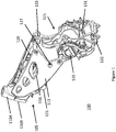
- FIG. 1 is a motorcycle chassis according to one embodiment.
- the motorcycle chassis 100 comprises a front bulkhead 105 and a rear bulkhead 125.
- the front bulkhead 105 and rear bulkhead 125 are the front and rear portions of the motorcycle chassis, respectively.
- the front bulkhead 105 includes a head tube 110, side panels 115, and one or more coolant tubes 120.
- the rear bulkhead includes a motor mount 130 and a motor controller mount (not visible in FIG. 1 , motor controller mount 301 shown in FIG. 3A and FIG. 4 ).
- the head tube 110 is a cylindrical component formed into the motorcycle chassis 100 to interface with a suspension component of the motorcycle such as a front fork (not depicted).
- the head tube 110 comprises an upper head tube 110A and a lower head tube 110B.
- the front fork of the motorcycle connects the front wheel to the chassis 100 and allows the front wheel to rotate and steer the motorcycle.
- the front fork may comprise suspension components that allow the front wheel to absorb bumps and imperfections in the road.
- motorcycle forks are well understood in the related field and thus will not be further described herein.
- the side panels 115 extend rearward from the head tube 110 towards the rear bulkhead 125.
- the side panels 115 are welded to the other components of the front bulkhead 105.
- the side panels 115 may be fixed to the other components of the front bulkhead 105 with bolts or other fastening mechanisms.
- the side panels 115 comprise flat panels with additional supports to provide structural rigidity to the front bulkhead 105.
- holes 116 are formed in the side panels 115.
- the holes 116 may serve the purpose of reducing the overall mass of the motorcycle chassis 100.
- the holes 116 may be drilled into the side panels 115 or the side panels 115 may be formed to include the holes 116.
- the side panels 115 are configured to function as a heat sink for transferring heat from a coolant fluid to the side panels 116.
- the side panels 115 are mounted to the rear bulkhead 125 via fasteners 117 such as bolts.
- One or more coolant tubes 120 are connected to the inner face of the side panels 115, in some embodiments.
- the coolant tubes 120 are welded to the inner face of the side panels 115 in some embodiments.
- the coolant tubes 120 are fixed to the side panels 115 via a fastening mechanism suitable for pipes such as welding or clamps.
- the coolant tubes 120 are pipes that allow coolant liquid (e.g., water or antifreeze) to flow through freely.
- the coolant tubes 120 have a circular cross section. In other embodiments, the coolant tubes 120 may have a square, ridged, or other cross section.
- the cross section of the coolant tubes 120 may vary in order to increase the efficiency at which the coolant tubes 120 can transfer heat from a coolant fluid to the side panels 115 of the motorcycle chassis 100. That is, the diameter of the coolant tubes 120 may vary along the length of the coolant tubes 120. Alternatively, the diameter of the coolant tubes 120 may be consistent along the length of the coolant tubes 120.
- the coolant tubes 120 are made of any material that has a high thermal conductivity such that the coolant tubes 120 can transfer the heat from the coolant fluid to the side panels 115.
- the coolant tubes 120 are made of aluminum or copper.
- the coolant tubes 120 may be made of titanium, carbon fiber, or any other material with a high thermal conductivity.
- the front bulkhead 105 also comprises a coolant pump 121 which circulates coolant fluid through the coolant tubes 120.
- the rear bulkhead 125 houses an electric motor and a motor controller that controls operation of the electric motor, in some embodiments.
- the electric motor is fixed to the rear bulkhead 125 and is housed inside the motor mount 130 (depicted in FIG. 2 ).
- the motor controller is fixed to the rear bulkhead 125 on the controller mount 301 (depicted in FIG. 3A and FIG. 4 ).
- the rear bulkhead 125 is formed to add rigidity and structural integrity to the motorcycle chassis 100.
- the rear bulkhead 125 is fixed to the front bulkhead 105 via fasteners 117 such as bolts. In other embodiments, the rear bulkhead 125 is welded to the front bulkhead 105.
- the rear bulkhead 125 also comprises a swingarm mount 131 to allow a swingarm of a motorcycle to be attached to the rear bulkhead 125.
- the swingarm of a motorcycle may comprise suspension components that allow the rear wheel of a motorcycle to absorb bumps and imperfections in the road.
- the rear bulkhead 125 may also comprise a skid frame mount 132 to allow a skid frame of a motorcycle to be mounted to the rear bulkhead 125.
- a motorcycle skid frame protects vital components of a motorcycle chassis and drivetrain.
- the skid frame mount 132 may allow the skid frame to pivot relative to the rear bulkhead, allowing for easier access to various components mounted within the front bulkhead 105 and rear bulkhead 125.
- the rear bulkhead 125 may also comprise a rear shock mount 133 to allow a rear shock to be mounted to the rear bulkhead 125.
- the rear shock may be mounted to both the swingarm and rear bulkhead 125 to allow the rear wheel of the motorcycle to absorb bumps and imperfections in the road.
- the rear bulkhead 125 is formed to include the different mounts such as the swingarm mount 131, the skidframe mount 132, and the rear shock mount 133. Alternatively, the mounts are welded onto the rear bulkhead 125.
- the motorcycle chassis 100 and its various components are made of an aluminum alloy. In other embodiments, the motorcycle chassis 100 may be made from various other metals, such as steel or titanium. In some embodiments, the motorcycle chassis 100 is constructed of a material that has a high heat capacity, in order to enable the motorcycle chassis to absorb as much of the generated heat as possible.
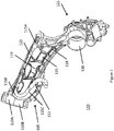
- FIG. 2 is a cutaway view of the motorcycle chassis depicted in FIG. 1 according to one embodiment.
- FIG. 2 illustrates a detailed view of the integrated coolant tube 120.
- the integrated coolant tube 120 extends and curves along the inner surface of the side panels 115.
- the coolant tube 120 is shaped in order to maximize the contact area between the coolant tube 120 and different edges of the side panels 115.
- the coolant tube 120 is in contact with the top edge 115A, front edge 115B, and front lower edge 115C of the side panels 115.
- the integrated coolant tube 120 is in contact with different edges of the side panels 115 to dissipate the heat from the coolant fluid flowing through the integrated coolant tube 120 to the motorcycle chassis 100 that functions as a heat sink.
- the coolant tube 120 is welded to the side panels 115 in some embodiments.
- the coolant tube may be welded at multiple positions along the side panels 115.
- the coolant tube 120 may be attached via other methods to the side panels 115 to facilitate heat transfer between the coolant tube and the side panel 115.
- the coolant tube 120 may be connected to the coolant pump 121 (depicted in FIG. 1 ) by a flexible connector 122.
- the flexible connector 122 is connected to one end of the coolant tube 120 and connects the coolant tube 120 to the coolant pump 121 to allow coolant liquid to flow between the coolant tube 120 and the coolant pump 121.
- the flexible connector 122 may be composed of a flexible material. Examples of the flexible connector 122 are a rubber hose or a metal flex pipe.
- the side panels 115 may also comprise reinforcing ribs 118 that add rigidity to the structure of the side panels 115.
- the ribs 118 are flat panels that protrude substantially perpendicularly from the side panel 115 and extend approximately 1 inch or less from the surface of the side panel 115. As shown in FIG. 2 , the reinforcing ribs 118 are positioned in a grid like structure such where a rib positioned in a first direction intersects with a rib positioned in a second direction.
- the ribs 118 are machined from the same piece of material as the side panel 115.
- the ribs 118 are individual components that are welded to the side panel 115. In some embodiments, there may be two or more ribs 118 that extend along varying directions.
- the side panels 115 also comprise a crossbar 119.
- the crossbar 119 is a flat panel that protrudes substantially perpendicularly from the side panel 115.
- the left side panel 115 and the right side panel 115 each comprise a crossbar 119, and the two crossbars 119 are joined in the middle of the front bulkhead.
- the crossbar 119 is a single piece that extends from the left side panel 115 to the right side panel 115.
- the crossbar 119 is welded to the side panels 115.
- the crossbar 119 is machined directly from the side panel 115.
- the crossbar 119 further adds rigidity to the side panels 115 and connects the left and right side panels together.
- the ribs 118 and crossbar 119 are made of an aluminum alloy.
- the ribs 118 and crossbar 119 may be made from various other metals, such as steel or titanium.
- FIG. 3A is a cross sectional view of the motorcycle chassis with integrated coolant tube according to one embodiment.
- the cross sectional view shown in FIG. 3A illustrates the motorcycle chassis 100 from the forward end with the head tube 110.
- the side panels 115, coolant tubes 120, and rear bulkhead 125 are visible.
- the coolant tubes 120 are shaped such that the contact area between the coolant tubes 120 and the side panels 115 is maximized, as described in FIG. 2 .
- the coolant tubes 120 are connected to the inlet port 415 and outlet port 420 (further described in FIG. 4 ) via a flexible connector 303.
- the motorcycle chassis 100 further comprises a controller mount 301, to which a motor controller housing 602 (further described in FIG. 6 ) is attached.
- the controller mount 301 is formed into the rear bulkhead 125.
- the motor controller mount 301 may comprise a mounting surface 405 (further described in FIG. 4 ), an interior cavity 410, and fastening locations 330.
- the mounting surface 405 is a substantially flat machined surface that mates with the motor controller housing 602.
- the mounting surface 405 may create a seal with the motor controller housing 602 such that a fluid, such as coolant fluid, may flow through or be contained between the motor controller mount 301 and the motor controller housing 602.
- the mounting surface 405 may have a raised lip or incorporate a gasket to provide a liquid-tight seal.
- the interior cavity 410 creates a space in-between the motor controller mount 301 and motor controller housing 602 for the fluid to flow through or be contained in.
- the interior cavity 410 is cast into the rear bulkhead 125.
- the interior cavity is machined or otherwise formed into the rear bulkhead 125.
- the fastening locations 330 comprise holes formed into the rear bulkhead 125 such that the motor controller housing 602 may be bolted to the motor controller mount 301 using fasteners inserted in the holes.
- the circular section 302 is further described below with reference to FIG. 3B and FIG 3C .
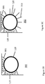
- FIG. 3B is a cross sectional view of a coolant tube 120 fixed to a side panel 115 of the motorcycle chassis 100.
- FIG. 3B depicts the circular area 302 in FIG. 3A .
- the coolant tube 120 is fixed to the side panel 115 via welds 305.
- a coolant fluid such as water or some other coolant fluid, flows through the coolant tube 120.
- the surface area of the welds 305 contacting both the side panel 115 and the coolant tube 120 is maximized. That is, a threshold amount of the surface of the coolant tube 120 is in contact with the side panel 115 via welds 305.
- the threshold amount of the surface of the coolant tube 120 is at least one quarter of the surface of the coolant tube 120. In other embodiments, the threshold amount is more or less than one quarter.
- the coolant tube 120 may comprise a circular cross section as depicted in FIG. 3B . In other embodiments, the coolant tube 120 may comprise different cross sectional shapes in order to increase the amount of heat transferred to the side panels 115. In other embodiments, the coolant tube 120 may be attached to the side panel 115 via a different method other than a weld.
- FIG. 3C is a cross sectional view of an alternative embodiment of the coolant tube 120 fixed to the side panel 115 of the motorcycle chassis 100.
- the coolant tube 120 is fixed to the side panel 115 via welds 305 as described above with reference to FIG. 3B .
- the embodiment of the coolant tube 120 depicted in FIG. 3C further comprises fins 310.
- the fins 310 are planar projections that extend substantially perpendicularly from the surface of the coolant tube 120.
- the fins 310 extend a maximum of 1 inch from the surface of the coolant tube 120.
- coolant tube 120 comprises seven fins 310.
- the coolant tube 120 may comprise more or fewer fins in other embodiments.
- the fins 310 extend down the entire length of the coolant tube 120. In other embodiments, the fins 310 may only be present on certain sections of the coolant tube 120. The fins 310 may allow some of the heat from the fluid circulating through the coolant tube 120 to be more efficiently transferred to the surrounding atmosphere via convection. In some embodiments, the fins 310 are welded to the coolant tube 120. In other embodiments, the coolant tube 120 and fins 310 are formed from a continuous piece of material, such as by extrusion. In some embodiments, the fins 310 are made of the same material as the coolant tube 120, such as aluminum or copper.
- FIG. 4 is a rear bulkhead 125 of the motorcycle chassis 100 according to one embodiment.
- the rear bulkhead 125 comprises a motor mount 130, a controller mount 301, an inlet port 415, and an outlet port 420 in one embodiment.
- the motor mount 130 comprises a cylindrical volume formed inside the rear bulkhead 125.
- An electric motor (described below with reference to FIG. 5 ) is inserted and fixed inside the motor mount 130.
- the motor controller mount 301 comprises a mounting surface 405 to which a motor controller housing is fixed.
- the mounting surface 405 is substantially flat. In some embodiments, an interior cavity 410 of the mounting surface 405 is recessed into the rear bulkhead 125 to allow fluid to flow between the motor controller and the rear bulkhead 125.
- the inlet port 415 allows the coolant fluid to flow from the coolant tubes 120 into the rear bulkhead 125 via a coolant inlet well 425 that extends from the inlet port 415.
- the coolant inlet well 425 is a hole that is cast in the rear bulkhead 125 to allow coolant from the coolant inlet port 415 to enter the motor controller mount 301.
- the coolant fluid then flows past the motor controller housing via the recessed interior cavity 410. As the fluid flows passes the motor controller, heat is transferred from the motor controller to the coolant fluid.
- the coolant fluid exits the motor controller mount 301 via a coolant outlet well 430 which extends to the motor mount 130.
- the coolant outlet well 430 is a hole that is cast in the rear bulkhead 125 to allow coolant fluid to exit the controller mount 301.
- the coolant fluid then circulates around the electric motor (further described with reference to FIG. 5 ), and then exits the rear bulkhead 125 via the outlet port 420 into another coolant tube 120.
- the coolant fluid flows to the outlet port 420 from the electric motor through a coolant return path 435 (further described below with reference to FIG. 6B ).
- the rear bulkhead 125 also comprises mounting holes 440 to allow the rear bulkhead 125 to be mounted to the front bulkhead 105 via fasteners 117 (depicted in FIG. 1 ).
- FIG. 5 is an electric motor assembly according to one embodiment.
- the electric motor assembly 505 comprises an electric motor 510 and a motor housing 515. Electric motors are well understood in the related field and are not described further herein.
- the motor housing 515 further comprises grooves 520 in some embodiments.
- the grooves 520 provide a path for the coolant fluid to flow around the electric motor 510. Heat generated by the electric motor 510 is transferred to the coolant fluid, and the coolant fluid flows through the rear bulkhead 125, exits the rear bulkhead 125 via the outlet port 420, and flows into the coolant tubes 120 as described above with reference to FIG. 4 .
- the grooves 520 distribute the coolant flow into multiple (e.g., 4) individual channels around the motor housing 515.
- the grooves 520 are shaped differently to optimize the flow of the coolant fluid around the motor housing 515. In some embodiments, the grooves 520 are machined into the motor housing 515. In some embodiments, the motor housing 515 is made from aluminum or other suitable material.
- FIG. 6A is a cross sectional view of a rear bulkhead assembly of a motorcycle chassis with an integrated motor controller housing according to one embodiment.
- the rear bulkhead assembly 600 comprises a rear bulkhead 601 and a motor controller housing 602.
- the rear bulkhead 601 is similar to the rear bulkhead 125 described above with reference to Figure 4 .
- the rear bulkhead 601 comprises the controller mount 301 described above with reference to Figure 4 .
- the motor controller housing 602 further comprises an interior cavity 621 in which a motor controller (also referred to as the inverter) is mounted.
- the motor controller housing 602 further comprises a coolant flow region 630 with coolant guide fins 635.
- the coolant flow region 630 may also be considered a coolant flow cavity.
- the coolant fluid that enters the rear bulkhead through the inlet port 415 flows through the coolant flow region 630 and is guided by the coolant guide fins 635.
- the coolant guide fins 635 are formed into the motor controller housing 602 by machining or as part of the casting process.
- the coolant guide fins 635 guide the coolant fluid to extract as much heat as possible from the motor controller housing 602 and are further discussed in reference to FIG. 7A .
- a motor controller is mounted in the interior cavity 621 such that the motor controller is flush against the dividing surface 640 between the interior cavity 621 and the coolant flow region 630. As shown in FIG.
- the coolant flow region 630 is a cavity on the other side of the motor controller housing 602 opposite to the interior cavity 621. This provides for the most efficient heat transfer from the motor controller to the coolant fluid.
- the motor controller is mounted in a different configuration which maximizes heat transfer from the motor controller to the coolant fluid.
- FIG. 6B is a different cross sectional view of the rear bulkhead assembly 600 described above with reference to FIG. 6A .
- the rear bulkhead assembly 600 comprises a rear bulkhead 601 and a motor controller housing 602.
- the rear bulkhead 601 comprises a coolant return path 435, described above with reference to FIG. 4 , which allows the coolant fluid to flow from the electric motor (housed in the electric motor housing 130) back up to the outlet port 420.
- the coolant return path 435 is cast, machined, or otherwise formed into the rear bulkhead 601.
- FIG. 7A and FIG. 7B illustrate a motor controller housing according to one embodiment.
- the motor controller housing depicted in FIG. 7A and FIG. 7B are similar to the motor controller housing 602 depicted in FIG. 6A .
- the motor controller housing 602 comprises an interior cavity 621 on one side, and a coolant flow region 630 with coolant guide fins 635 on the other side.
- the coolant guide fins 635 are arranged to encourage turbulent flow of the coolant fluid. Turbulent flow allows for more effective heat transfer than laminar flow by allowing the fluid to break through a boundary layer that may be present near the surface of the motor controller housing 602.
- each of the coolant guide fins is elliptical in shape.
- one or more of the coolant guide fins 710A are angled to the left to varying degrees (i.e., a first direction)
- one or more of the coolant guide fins 710B are vertically oriented (i.e., a second direction)
- one or more of the coolant guide fins 710C are angled to the right to varying degrees (i.e., a third direction).
- some of the coolant guide fins 710 may be angled horizontally.
- coolant guide fins 635 include fins orientated in different directions with respect to each other.
- the angle, position, and size of each of the fins may be changed independently to vary the turbulence introduced into the flow of the coolant fluid.
- the motor controller housing 602 also includes a mounting surface 645 that mounts to the mounting surface 405 of the motor controller mount 301.
- a motor controller (or inverter) is mounted in the interior cavity 621 to the flat surface 705.
- the motor controller is shaped to maximize the contact area between the motor controller and the flat surface 705. This maximizes the amount of heat transfer between the motor controller and the controller housing 602.
- the controller housing 602 then transfers the heat to the coolant fluid which flows through the coolant flow region 630.
- the controller housing 602 is formed by casting and is made from aluminum. In other embodiments, the controller housing 602 is made of various other thermally conductive materials.
- the motorcycle chassis 100 functions primarily as a heat sink, in some embodiments.
- the thermal mass (or heat capacity) of the motorcycle chassis 100 is large enough to absorb the amount of heat generated by the electric motor and various other components of the electric vehicle. Allowing the motorcycle chassis 100 to absorb the generated heat eliminates the heat from the electric motor and various other components of the electric vehicle.
- the motorcycle chassis 100 dissipates some of the absorbed heat through convection with the surrounding atmosphere.
- the motorcycle chassis 100 is not necessarily optimized for dissipating heat through convection, in some embodiments. Because the amount of heat generated by the electric motor and various components is relatively low, dissipating heat via convection is not necessary.
- a coolant fluid is circulated from the coolant tubes 120 in the front bulkhead 105 through the rear bulkhead 125 and back.
- the coolant fluid flows into the inlet port 415 past the controller mount 301, through the grooves 520 of the motor housing 515, and then exits the rear bulkhead 125 through the outlet port 420.
- a coolant pump 121 circulates the coolant fluid.
- the coolant fluid is water.
- the coolant fluid is an automotive coolant fluid used in typical automotive applications.
- an ICE-powered vehicle In contrast, a typical vehicle powered by an internal combustion engine (ICE) generates a greater amount of waste heat, and the thermal mass of the chassis is not great enough to absorb the generated waste heat. Therefore, an ICE-powered vehicle often utilizes a radiator system to more efficiently dissipate the generated waste heat.
- the radiator setup typically circulates a coolant fluid around the ICE such that heat from the ICE is transferred to the coolant fluid via conduction. Then, the coolant fluid is circulated through a radiator, which allows the coolant fluid to efficiently dissipate the absorbed heat to the atmosphere via convection.
Landscapes
- Engineering & Computer Science (AREA)
- Mechanical Engineering (AREA)
- Transportation (AREA)
- Chemical & Material Sciences (AREA)
- Combustion & Propulsion (AREA)
- Power Engineering (AREA)
- Automatic Cycles, And Cycles In General (AREA)
- Electric Propulsion And Braking For Vehicles (AREA)
- Physics & Mathematics (AREA)
- Thermal Sciences (AREA)
- Life Sciences & Earth Sciences (AREA)
- Sustainable Development (AREA)
- Sustainable Energy (AREA)
Claims (14)
- Chassis eines elektrischen Motorrads (100), umfassend:ein Hauptrohr (110), welches dazu eingerichtet ist, eine Aufhängungskomponente aufzunehmen;ein Seitenpaneel (115), welches sich von dem Hauptrohr nach hinten erstreckt, wobei das Seitenpaneel eine äußere Fläche und eine innere Fläche umfasst; undeine Kühlmittelleitung (120), welche sich entlang der inneren Seite des Seitenpaneels erstreckt und die innere Fläche des Seitenpaneels thermisch kontaktiert, wobei die Kühlmittelleitung Wärme von einem Kühlmittelfluid, welches in der Kühlmittelleitung strömt, an das Seitenpaneel über den thermischen Kontakt transferiert;wobei das Chassis des elektrischen Motorrads dadurch gekennzeichnet ist, dass es ferner eine hintere Trennwand (125) umfasst, umfassend:eine Motoranbringung (130), welche in der hinteren Trennwand gebildet ist und einen elektrischen Motor in der hinteren Trennwand aufnimmt;eine Motor-Regel-/Steuereinheit-Anbringung (301), welche in der hinteren Trennwand gebildet ist und ein Motor-Regel-/Steuereinheit-Gehäuse (602) mit der hinteren Trennwand verbindet; undeine Pendelarm-Anbringung (131), welche einen Pendelarm des elektrischen Motorrads mit der hinteren Trennwand verbindet.
- Chassis nach Anspruch 1, wobei die Kühlmittelleitung an die innere Fläche des Seitenpaneels an einer Mehrzahl von Positionen entlang des Seitenpaneels geschweißt ist.
- Chassis nach Anspruch 1, wobei ein Durchmesser der Kühlmittelleitung entlang einer Länge der Kühlmittelleitung variiert.
- Chassis nach Anspruch 1, wobei die Kühlmittelleitung entweder Aluminium, Kupfer, Titan oder eine Carbonfaser umfasst.
- Chassis nach Anspruch 1, wobei die innere Fläche des Seitenpaneels eine Mehrzahl von Rändern umfasst und die Kühlmittelleitung in thermischem Kontakt mit der Mehrzahl von Rändern ist.
- Chassis nach Anspruch 1, ferner umfassend:
eine flexible Verbindungseinheit (122), welche ein Ende der Kühlmittelleitung mit einer Kühlmittelpumpe (121) verbindet, welche das Kühlmittelfluid durch die Kühlmittelleitung pumpt. - Chassis nach Anspruch 1, wobei die Motor-Regel-/Steuereinheit-Anbringung umfasst:eine im Wesentlichen flache Anbringungsfläche (405), welche eine Mehrzahl von Anbringungslöchern (440) umfasst;einen ausgenommenen Abschnitt der Motor-Regel-/Steuereinheit-Anbringung, welche sich von der Anbringungsfläche in die hintere Trennwand erstreckt;eine erste Kühlmittelquelle (425), welche dem Kühlmittelfluid von der Kühlmittelleitung erlaubt, in den ausgenommenen Abschnitt der Regel-/Steuereinheit-Anbringung zu strömen; undeine zweite Kühlmittelquelle (430), welche dem Kühlmittelfluid erlaubt, den ausgenommenen Abschnitt der Motor-Regel-/Steuereinheit-Anbringung zu der Motor-Anbringung zu verlassen.
- Chassis nach Anspruch 7, ferner umfassend ein Motor-Regel-/Steuereinheit-Gehäuse, umfassend:einen inneren Hohlraum (621), welcher an einer ersten Seite des Motor-Regel-/Steuereinheit-Gehäuses gebildet ist, wobei der innere Hohlraum eine Motor-Regel-/Steuereinheit aufnimmt, welche einen Betrieb des elektrischen Motors regelt/steuert;eine im Wesentlichen flache Anbringungsfläche, welche an einer zweiten Seite des Motor-Regel-/Steuereinheit-Gehäuses gebildet ist, wobei die Anbringungsfläche das Motor-Regel-/Steuereinheit-Gehäuse mit der Anbringungsfläche der Regel-/Steuereinheit-Anbringung unter Verwendung von Befestigungsmitteln koppelt, welche in die Mehrzahl von Anbringungslöchern eingesetzt sind; undeinen Kühlmittel-Strömungshohlraum (630), welcher sich von der Anbringungsfläche an der zweiten Seite des Motor-Regel-/Steuereinheit-Gehäuses in das Motor-Regel-/Steuereinheit-Gehäuse erstreckt, wobei der Kühlmittel-Strömungshohlraum eine Mehrzahl von Kühlmittel-Führungsrippen umfasst, welche das Kühlmittelfluid zwischen dem Kühlmittel-Strömungshohlraum des Motor-Regel-/Steuereinheit-Gehäuses und dem ausgenommenen Abschnitt der Regel-/Steuereinheit-Anbringung führen, um Wärme von der Motor-Regel-/Steuereinheit an das Kühlmittelfluid zu transferieren.
- Chassis nach Anspruch 7, wobei die hintere Trennwand ferner umfasst:einen Einlassanschluss (415), welcher dazu eingerichtet ist, sich mit einem Ende der Kühlmittelleitung zu verbinden; undeinen Auslassanschluss (420), welcher dazu eingerichtet ist, sich mit einem anderen Ende einer Kühlmittelleitung zu verbinden.
- Chassis nach Anspruch 1, wobei die Kühlmittelleitung eine Mehrzahl von Rippen (310) umfasst, welche sich rechtwinklig von einer Fläche der Kühlmittelleitung erstrecken.
- Chassis nach Anspruch 10, wobei sich die Mehrzahl von Rippen entlang einer gesamten Länge der Kühlmittelleitung erstrecken; oder wobei die Mehrzahl von Rippen an einem Abschnitt der Kühlmittelleitung positioniert sind und verbleibende Abschnitte der Kühlmittelleitung frei von der Mehrzahl von Rippen sind.
- Chassis nach Anspruch 10, wobei die Kühlmittelleitung gebildet ist, um die Mehrzahl von Rippen zu umfassen; oder wobei die Mehrzahl von Rippen an die Kühlmittelleitung geschweißt sind.
- Chassis nach Anspruch 1, wobei die innere Fläche des Seitenpaneels Verstärkungsrippen (118) umfasst, welche sich im Wesentlichen rechtwinklig von der inneren Fläche des Seitenpaneels erstrecken; wobei, optional, eine erste Rippe der Verstärkungsrippen in einer ersten Richtung positioniert ist und eine zweite Rippe der Verstärkungsrippen in einer zweiten Richtung positioniert ist und die erste Rippe schneidet.
- Chassis nach Anspruch 13, wobei das Seitenpaneel ein oder mehrere Löcher umfasst, welche in dem Seitenpaneel gebildet sind.
Applications Claiming Priority (3)
| Application Number | Priority Date | Filing Date | Title |
|---|---|---|---|
| US201462019000P | 2014-06-30 | 2014-06-30 | |
| US14/753,718 US9415673B2 (en) | 2014-06-30 | 2015-06-29 | Integrated chassis heatsink for electric vehicles |
| PCT/US2015/038592 WO2016004064A1 (en) | 2014-06-30 | 2015-06-30 | Integrated chassis heatsink for electric vehicles |
Publications (3)
| Publication Number | Publication Date |
|---|---|
| EP3161900A1 EP3161900A1 (de) | 2017-05-03 |
| EP3161900A4 EP3161900A4 (de) | 2018-03-07 |
| EP3161900B1 true EP3161900B1 (de) | 2020-01-01 |
Family
ID=54929608
Family Applications (1)
| Application Number | Title | Priority Date | Filing Date |
|---|---|---|---|
| EP15815100.1A Active EP3161900B1 (de) | 2014-06-30 | 2015-06-30 | Integrierter fahrgestellkühlkörper für elektrofahrzeuge |
Country Status (4)
| Country | Link |
|---|---|
| US (2) | US9415673B2 (de) |
| EP (1) | EP3161900B1 (de) |
| ES (1) | ES2777308T3 (de) |
| WO (1) | WO2016004064A1 (de) |
Families Citing this family (14)
| Publication number | Priority date | Publication date | Assignee | Title |
|---|---|---|---|---|
| US9434441B1 (en) * | 2014-08-12 | 2016-09-06 | Faster Faster Inc. | Motorcycle frame head stock |
| DE102015226023A1 (de) * | 2015-12-18 | 2017-06-22 | Siemens Aktiengesellschaft | Flüssigkeitsgekühlte, elektrische Antriebskomponente, Antriebsstrang, Fahrzeug und Verfahren |
| JP6489715B2 (ja) * | 2017-03-27 | 2019-03-27 | 本田技研工業株式会社 | 鞍乗り型車両の車体構造 |
| JP6982169B2 (ja) * | 2018-03-29 | 2021-12-17 | 本田技研工業株式会社 | 鞍乗型電動車両 |
| WO2019210242A1 (en) * | 2018-04-27 | 2019-10-31 | FUELL Inc. | Electric saddle type vehicle chassis |
| US11753101B2 (en) | 2018-04-27 | 2023-09-12 | FUELL Inc. | Electric saddle type vehicle with storage areas |
| DE102018208925A1 (de) * | 2018-06-06 | 2019-12-12 | Bayerische Motoren Werke Aktiengesellschaft | Verfahren zum Abschirmen von Bauteilen |
| US11117637B2 (en) * | 2018-07-25 | 2021-09-14 | Harley-Davidson Motor Company Group, LLC | Motorcycle frame |
| WO2020176858A2 (en) | 2019-02-28 | 2020-09-03 | FUELL Inc. | Electric saddle type vehicle |
| US12485981B2 (en) | 2021-03-24 | 2025-12-02 | Polaris Industries Inc. | Electric recreational vehicle |
| CA3236381A1 (en) | 2021-10-29 | 2023-05-04 | Yannick BOURQUE | Electric vehicle with an electric powerpack arrangement |
| US20250136087A1 (en) * | 2022-01-31 | 2025-05-01 | Polaris Industries Inc. | Electric or hybrid vehicle |
| DE102022104227A1 (de) | 2022-02-23 | 2023-08-24 | Dr. Ing. H.C. F. Porsche Aktiengesellschaft | Kraftfahrzeug mit einem elektrischen Antrieb und Verfahren zur Kühlung eines elektrischen Antriebs eines Kraftfahrzeugs |
| US20240076006A1 (en) * | 2022-09-07 | 2024-03-07 | Damon Motors Inc. | Monocoque shear wall as cooling plate |
Family Cites Families (12)
| Publication number | Priority date | Publication date | Assignee | Title |
|---|---|---|---|---|
| JPH07288949A (ja) | 1994-04-13 | 1995-10-31 | Nippondenso Co Ltd | 車両駆動用電動機 |
| JP3886696B2 (ja) | 1999-04-27 | 2007-02-28 | アイシン・エィ・ダブリュ株式会社 | 駆動装置 |
| US6173758B1 (en) | 1999-08-02 | 2001-01-16 | General Motors Corporation | Pin fin heat sink and pin fin arrangement therein |
| US6326765B1 (en) * | 2000-10-04 | 2001-12-04 | Vectrix Corporation | Electric scooter with on-board charging system |
| US20020177035A1 (en) | 2001-05-23 | 2002-11-28 | Alcatel | Thermal management blanketing and jacketing for battery system modules |
| US7255191B2 (en) * | 2003-10-31 | 2007-08-14 | Vectrix Corporation | Composite construction vehicle frame |
| TW200817579A (en) * | 2006-06-14 | 2008-04-16 | Vectrix Corp | Electric vehicle air cooling system |
| US7807290B2 (en) * | 2006-12-01 | 2010-10-05 | Zero Motorcycles Inc. | Battery cell assembly |
| US20080185130A1 (en) | 2007-02-07 | 2008-08-07 | Behr America | Heat exchanger with extruded cooling tubes |
| US8212438B2 (en) * | 2010-01-19 | 2012-07-03 | U.S. Alternate Energy, LLC | Coolant system for electric motorcycle |
| US8672077B2 (en) | 2011-08-02 | 2014-03-18 | Faster Faster Inc. | Integrated cast motorcycle chassis and motor housing |
| CN103575140A (zh) | 2012-07-19 | 2014-02-12 | 格伦格斯有限公司 | 用于电力电子设备和电池冷却的具有焊接管的紧凑型铝换热器 |
-
2015
- 2015-06-29 US US14/753,718 patent/US9415673B2/en active Active
- 2015-06-30 ES ES15815100T patent/ES2777308T3/es active Active
- 2015-06-30 WO PCT/US2015/038592 patent/WO2016004064A1/en not_active Ceased
- 2015-06-30 EP EP15815100.1A patent/EP3161900B1/de active Active
-
2016
- 2016-07-13 US US15/209,549 patent/US9446659B1/en active Active
Non-Patent Citations (1)
| Title |
|---|
| None * |
Also Published As
| Publication number | Publication date |
|---|---|
| WO2016004064A1 (en) | 2016-01-07 |
| US20150375596A1 (en) | 2015-12-31 |
| US9415673B2 (en) | 2016-08-16 |
| ES2777308T3 (es) | 2020-08-04 |
| EP3161900A4 (de) | 2018-03-07 |
| EP3161900A1 (de) | 2017-05-03 |
| US9446659B1 (en) | 2016-09-20 |
Similar Documents
| Publication | Publication Date | Title |
|---|---|---|
| US9446659B1 (en) | Integrated chassis heatsink for electric vehicles | |
| JP6154805B2 (ja) | 電気モータを冷却する装置 | |
| US10012130B2 (en) | Cooling system | |
| CN111244573B (zh) | 一种基于振动能量回收的汽车动力电池强化散热装置 | |
| US8579060B2 (en) | Double heat exchanger radiator assembly | |
| US7353898B1 (en) | Integrated heat exchanger and engine mount for a snowmobile | |
| CN205213192U (zh) | 一种冷却壳体及具有所述冷却壳体的电机控制器 | |
| JP4802196B2 (ja) | 水陸両用車の排気冷却システム | |
| TWI715666B (zh) | 機車引擎冷卻設備 | |
| JPWO2023007971A5 (de) | ||
| BR102016024487B1 (pt) | Conjunto de ingresso e desaeração integrado e veículo de trabalho | |
| EP3581775B1 (de) | Fahrzeug mit "v" förmigem, zweifach-kühler | |
| US20160091261A1 (en) | Heat exchanger support assembly | |
| CN212401345U (zh) | 一种用于转向助力系统的转向油冷却装置及汽车 | |
| JP6688825B2 (ja) | 車両 | |
| JP2007200915A (ja) | 冷却フィンおよび冷却装置 | |
| EP2159145B1 (de) | Anordnung für ein Motorrad mit einem Kühler und einer Batterie und ein mit dieser Anordnung ausgestattetes Motorrad | |
| CN215633284U (zh) | 全地形车及其散热系统 | |
| JP3980164B2 (ja) | 熱交換器 | |
| JP2015145150A (ja) | 車両前部構造 | |
| CN210892786U (zh) | 车辆复合散热装置 | |
| JPS6354590A (ja) | オイル・ク−ラ | |
| CN111688802A (zh) | 一种用于转向助力系统的转向油冷却装置及汽车 | |
| KR20110002088U (ko) | 차량용 냉각수 순환장치 | |
| CN216253686U (zh) | 一种电动汽车主驱多合一立体水道散热装置 |
Legal Events
| Date | Code | Title | Description |
|---|---|---|---|
| STAA | Information on the status of an ep patent application or granted ep patent |
Free format text: STATUS: THE INTERNATIONAL PUBLICATION HAS BEEN MADE |
|
| PUAI | Public reference made under article 153(3) epc to a published international application that has entered the european phase |
Free format text: ORIGINAL CODE: 0009012 |
|
| STAA | Information on the status of an ep patent application or granted ep patent |
Free format text: STATUS: REQUEST FOR EXAMINATION WAS MADE |
|
| 17P | Request for examination filed |
Effective date: 20170118 |
|
| AK | Designated contracting states |
Kind code of ref document: A1 Designated state(s): AL AT BE BG CH CY CZ DE DK EE ES FI FR GB GR HR HU IE IS IT LI LT LU LV MC MK MT NL NO PL PT RO RS SE SI SK SM TR |
|
| AX | Request for extension of the european patent |
Extension state: BA ME |
|
| DAV | Request for validation of the european patent (deleted) | ||
| DAX | Request for extension of the european patent (deleted) | ||
| A4 | Supplementary search report drawn up and despatched |
Effective date: 20180201 |
|
| RIC1 | Information provided on ipc code assigned before grant |
Ipc: H01M 10/65 20140101AFI20180126BHEP Ipc: B60L 11/18 20060101ALI20180126BHEP |
|
| STAA | Information on the status of an ep patent application or granted ep patent |
Free format text: STATUS: EXAMINATION IS IN PROGRESS |
|
| 17Q | First examination report despatched |
Effective date: 20180712 |
|
| GRAP | Despatch of communication of intention to grant a patent |
Free format text: ORIGINAL CODE: EPIDOSNIGR1 |
|
| STAA | Information on the status of an ep patent application or granted ep patent |
Free format text: STATUS: GRANT OF PATENT IS INTENDED |
|
| RAP1 | Party data changed (applicant data changed or rights of an application transferred) |
Owner name: FASTER FASTER INC. |
|
| RIN1 | Information on inventor provided before grant (corrected) |
Inventor name: BLAIN, CHRISTOPHER C. Inventor name: SAND, JEFF W. Inventor name: DORRESTEYN, DEREK A. |
|
| INTG | Intention to grant announced |
Effective date: 20181210 |
|
| GRAS | Grant fee paid |
Free format text: ORIGINAL CODE: EPIDOSNIGR3 |
|
| GRAA | (expected) grant |
Free format text: ORIGINAL CODE: 0009210 |
|
| STAA | Information on the status of an ep patent application or granted ep patent |
Free format text: STATUS: THE PATENT HAS BEEN GRANTED |
|
| AK | Designated contracting states |
Kind code of ref document: B1 Designated state(s): AL AT BE BG CH CY CZ DE DK EE ES FI FR GB GR HR HU IE IS IT LI LT LU LV MC MK MT NL NO PL PT RO RS SE SI SK SM TR |
|
| REG | Reference to a national code |
Ref country code: GB Ref legal event code: FG4D |
|
| REG | Reference to a national code |
Ref country code: CH Ref legal event code: EP Ref country code: AT Ref legal event code: REF Ref document number: 1220944 Country of ref document: AT Kind code of ref document: T Effective date: 20200115 |
|
| REG | Reference to a national code |
Ref country code: DE Ref legal event code: R096 Ref document number: 602015044832 Country of ref document: DE |
|
| REG | Reference to a national code |
Ref country code: IE Ref legal event code: FG4D |
|
| REG | Reference to a national code |
Ref country code: NL Ref legal event code: MP Effective date: 20200101 |
|
| REG | Reference to a national code |
Ref country code: DE Ref legal event code: R082 Ref document number: 602015044832 Country of ref document: DE Representative=s name: PATENT- UND RECHTSANWAELTE DR. SOLF & ZAPF, DE Ref country code: DE Ref legal event code: R081 Ref document number: 602015044832 Country of ref document: DE Owner name: BOMBARDIER RECREATIONAL PRODUCTS INC., VALCOUR, CA Free format text: FORMER OWNER: FASTER FASTER INC., SAN FRANCISCO, CA, US Ref country code: DE Ref legal event code: R082 Ref document number: 602015044832 Country of ref document: DE Representative=s name: DR. SOLF & ZAPF PATENT- UND RECHTSANWAELTE, DE Ref country code: DE Ref legal event code: R082 Ref document number: 602015044832 Country of ref document: DE Representative=s name: DR. SOLF & ZAPF PATENT- UND RECHTSANWALTS PART, DE |
|
| REG | Reference to a national code |
Ref country code: LT Ref legal event code: MG4D |
|
| REG | Reference to a national code |
Ref country code: GB Ref legal event code: 732E Free format text: REGISTERED BETWEEN 20200618 AND 20200624 |
|
| PG25 | Lapsed in a contracting state [announced via postgrant information from national office to epo] |
Ref country code: NL Free format text: LAPSE BECAUSE OF FAILURE TO SUBMIT A TRANSLATION OF THE DESCRIPTION OR TO PAY THE FEE WITHIN THE PRESCRIBED TIME-LIMIT Effective date: 20200101 Ref country code: RS Free format text: LAPSE BECAUSE OF FAILURE TO SUBMIT A TRANSLATION OF THE DESCRIPTION OR TO PAY THE FEE WITHIN THE PRESCRIBED TIME-LIMIT Effective date: 20200101 Ref country code: FI Free format text: LAPSE BECAUSE OF FAILURE TO SUBMIT A TRANSLATION OF THE DESCRIPTION OR TO PAY THE FEE WITHIN THE PRESCRIBED TIME-LIMIT Effective date: 20200101 Ref country code: PT Free format text: LAPSE BECAUSE OF FAILURE TO SUBMIT A TRANSLATION OF THE DESCRIPTION OR TO PAY THE FEE WITHIN THE PRESCRIBED TIME-LIMIT Effective date: 20200527 Ref country code: NO Free format text: LAPSE BECAUSE OF FAILURE TO SUBMIT A TRANSLATION OF THE DESCRIPTION OR TO PAY THE FEE WITHIN THE PRESCRIBED TIME-LIMIT Effective date: 20200401 Ref country code: LT Free format text: LAPSE BECAUSE OF FAILURE TO SUBMIT A TRANSLATION OF THE DESCRIPTION OR TO PAY THE FEE WITHIN THE PRESCRIBED TIME-LIMIT Effective date: 20200101 Ref country code: CZ Free format text: LAPSE BECAUSE OF FAILURE TO SUBMIT A TRANSLATION OF THE DESCRIPTION OR TO PAY THE FEE WITHIN THE PRESCRIBED TIME-LIMIT Effective date: 20200101 |
|
| REG | Reference to a national code |
Ref country code: ES Ref legal event code: FG2A Ref document number: 2777308 Country of ref document: ES Kind code of ref document: T3 Effective date: 20200804 |
|
| PG25 | Lapsed in a contracting state [announced via postgrant information from national office to epo] |
Ref country code: LV Free format text: LAPSE BECAUSE OF FAILURE TO SUBMIT A TRANSLATION OF THE DESCRIPTION OR TO PAY THE FEE WITHIN THE PRESCRIBED TIME-LIMIT Effective date: 20200101 Ref country code: SE Free format text: LAPSE BECAUSE OF FAILURE TO SUBMIT A TRANSLATION OF THE DESCRIPTION OR TO PAY THE FEE WITHIN THE PRESCRIBED TIME-LIMIT Effective date: 20200101 Ref country code: BG Free format text: LAPSE BECAUSE OF FAILURE TO SUBMIT A TRANSLATION OF THE DESCRIPTION OR TO PAY THE FEE WITHIN THE PRESCRIBED TIME-LIMIT Effective date: 20200401 Ref country code: GR Free format text: LAPSE BECAUSE OF FAILURE TO SUBMIT A TRANSLATION OF THE DESCRIPTION OR TO PAY THE FEE WITHIN THE PRESCRIBED TIME-LIMIT Effective date: 20200402 Ref country code: IS Free format text: LAPSE BECAUSE OF FAILURE TO SUBMIT A TRANSLATION OF THE DESCRIPTION OR TO PAY THE FEE WITHIN THE PRESCRIBED TIME-LIMIT Effective date: 20200501 Ref country code: HR Free format text: LAPSE BECAUSE OF FAILURE TO SUBMIT A TRANSLATION OF THE DESCRIPTION OR TO PAY THE FEE WITHIN THE PRESCRIBED TIME-LIMIT Effective date: 20200101 |
|
| PGFP | Annual fee paid to national office [announced via postgrant information from national office to epo] |
Ref country code: IT Payment date: 20200519 Year of fee payment: 6 |
|
| PGFP | Annual fee paid to national office [announced via postgrant information from national office to epo] |
Ref country code: AT Payment date: 20200520 Year of fee payment: 6 |
|
| REG | Reference to a national code |
Ref country code: DE Ref legal event code: R097 Ref document number: 602015044832 Country of ref document: DE |
|
| PG25 | Lapsed in a contracting state [announced via postgrant information from national office to epo] |
Ref country code: SM Free format text: LAPSE BECAUSE OF FAILURE TO SUBMIT A TRANSLATION OF THE DESCRIPTION OR TO PAY THE FEE WITHIN THE PRESCRIBED TIME-LIMIT Effective date: 20200101 Ref country code: EE Free format text: LAPSE BECAUSE OF FAILURE TO SUBMIT A TRANSLATION OF THE DESCRIPTION OR TO PAY THE FEE WITHIN THE PRESCRIBED TIME-LIMIT Effective date: 20200101 Ref country code: DK Free format text: LAPSE BECAUSE OF FAILURE TO SUBMIT A TRANSLATION OF THE DESCRIPTION OR TO PAY THE FEE WITHIN THE PRESCRIBED TIME-LIMIT Effective date: 20200101 Ref country code: SK Free format text: LAPSE BECAUSE OF FAILURE TO SUBMIT A TRANSLATION OF THE DESCRIPTION OR TO PAY THE FEE WITHIN THE PRESCRIBED TIME-LIMIT Effective date: 20200101 Ref country code: RO Free format text: LAPSE BECAUSE OF FAILURE TO SUBMIT A TRANSLATION OF THE DESCRIPTION OR TO PAY THE FEE WITHIN THE PRESCRIBED TIME-LIMIT Effective date: 20200101 |
|
| PGFP | Annual fee paid to national office [announced via postgrant information from national office to epo] |
Ref country code: ES Payment date: 20200701 Year of fee payment: 6 |
|
| PLBE | No opposition filed within time limit |
Free format text: ORIGINAL CODE: 0009261 |
|
| STAA | Information on the status of an ep patent application or granted ep patent |
Free format text: STATUS: NO OPPOSITION FILED WITHIN TIME LIMIT |
|
| 26N | No opposition filed |
Effective date: 20201002 |
|
| PG25 | Lapsed in a contracting state [announced via postgrant information from national office to epo] |
Ref country code: MC Free format text: LAPSE BECAUSE OF FAILURE TO SUBMIT A TRANSLATION OF THE DESCRIPTION OR TO PAY THE FEE WITHIN THE PRESCRIBED TIME-LIMIT Effective date: 20200101 |
|
| REG | Reference to a national code |
Ref country code: CH Ref legal event code: PL |
|
| PG25 | Lapsed in a contracting state [announced via postgrant information from national office to epo] |
Ref country code: SI Free format text: LAPSE BECAUSE OF FAILURE TO SUBMIT A TRANSLATION OF THE DESCRIPTION OR TO PAY THE FEE WITHIN THE PRESCRIBED TIME-LIMIT Effective date: 20200101 Ref country code: PL Free format text: LAPSE BECAUSE OF FAILURE TO SUBMIT A TRANSLATION OF THE DESCRIPTION OR TO PAY THE FEE WITHIN THE PRESCRIBED TIME-LIMIT Effective date: 20200101 |
|
| PG25 | Lapsed in a contracting state [announced via postgrant information from national office to epo] |
Ref country code: LU Free format text: LAPSE BECAUSE OF NON-PAYMENT OF DUE FEES Effective date: 20200630 |
|
| REG | Reference to a national code |
Ref country code: BE Ref legal event code: MM Effective date: 20200630 |
|
| PG25 | Lapsed in a contracting state [announced via postgrant information from national office to epo] |
Ref country code: IE Free format text: LAPSE BECAUSE OF NON-PAYMENT OF DUE FEES Effective date: 20200630 Ref country code: CH Free format text: LAPSE BECAUSE OF NON-PAYMENT OF DUE FEES Effective date: 20200630 Ref country code: LI Free format text: LAPSE BECAUSE OF NON-PAYMENT OF DUE FEES Effective date: 20200630 |
|
| PG25 | Lapsed in a contracting state [announced via postgrant information from national office to epo] |
Ref country code: BE Free format text: LAPSE BECAUSE OF NON-PAYMENT OF DUE FEES Effective date: 20200630 |
|
| REG | Reference to a national code |
Ref country code: AT Ref legal event code: UEP Ref document number: 1220944 Country of ref document: AT Kind code of ref document: T Effective date: 20200101 |
|
| REG | Reference to a national code |
Ref country code: AT Ref legal event code: MM01 Ref document number: 1220944 Country of ref document: AT Kind code of ref document: T Effective date: 20210630 |
|
| PG25 | Lapsed in a contracting state [announced via postgrant information from national office to epo] |
Ref country code: AT Free format text: LAPSE BECAUSE OF NON-PAYMENT OF DUE FEES Effective date: 20210630 |
|
| PG25 | Lapsed in a contracting state [announced via postgrant information from national office to epo] |
Ref country code: TR Free format text: LAPSE BECAUSE OF FAILURE TO SUBMIT A TRANSLATION OF THE DESCRIPTION OR TO PAY THE FEE WITHIN THE PRESCRIBED TIME-LIMIT Effective date: 20200101 Ref country code: MT Free format text: LAPSE BECAUSE OF FAILURE TO SUBMIT A TRANSLATION OF THE DESCRIPTION OR TO PAY THE FEE WITHIN THE PRESCRIBED TIME-LIMIT Effective date: 20200101 Ref country code: CY Free format text: LAPSE BECAUSE OF FAILURE TO SUBMIT A TRANSLATION OF THE DESCRIPTION OR TO PAY THE FEE WITHIN THE PRESCRIBED TIME-LIMIT Effective date: 20200101 |
|
| PG25 | Lapsed in a contracting state [announced via postgrant information from national office to epo] |
Ref country code: MK Free format text: LAPSE BECAUSE OF FAILURE TO SUBMIT A TRANSLATION OF THE DESCRIPTION OR TO PAY THE FEE WITHIN THE PRESCRIBED TIME-LIMIT Effective date: 20200101 Ref country code: AL Free format text: LAPSE BECAUSE OF FAILURE TO SUBMIT A TRANSLATION OF THE DESCRIPTION OR TO PAY THE FEE WITHIN THE PRESCRIBED TIME-LIMIT Effective date: 20200101 |
|
| PG25 | Lapsed in a contracting state [announced via postgrant information from national office to epo] |
Ref country code: IT Free format text: LAPSE BECAUSE OF NON-PAYMENT OF DUE FEES Effective date: 20210630 |
|
| REG | Reference to a national code |
Ref country code: ES Ref legal event code: FD2A Effective date: 20220830 |
|
| PG25 | Lapsed in a contracting state [announced via postgrant information from national office to epo] |
Ref country code: ES Free format text: LAPSE BECAUSE OF NON-PAYMENT OF DUE FEES Effective date: 20210701 |
|
| PGFP | Annual fee paid to national office [announced via postgrant information from national office to epo] |
Ref country code: DE Payment date: 20250626 Year of fee payment: 11 |
|
| PGFP | Annual fee paid to national office [announced via postgrant information from national office to epo] |
Ref country code: GB Payment date: 20250617 Year of fee payment: 11 |
|
| PGFP | Annual fee paid to national office [announced via postgrant information from national office to epo] |
Ref country code: FR Payment date: 20250624 Year of fee payment: 11 |