EP3159472B1 - Vertikal faltbare tür - Google Patents
Vertikal faltbare tür Download PDFInfo
- Publication number
- EP3159472B1 EP3159472B1 EP15191043.7A EP15191043A EP3159472B1 EP 3159472 B1 EP3159472 B1 EP 3159472B1 EP 15191043 A EP15191043 A EP 15191043A EP 3159472 B1 EP3159472 B1 EP 3159472B1
- Authority
- EP
- European Patent Office
- Prior art keywords
- door
- support member
- ribs
- rib
- door leaves
- Prior art date
- Legal status (The legal status is an assumption and is not a legal conclusion. Google has not performed a legal analysis and makes no representation as to the accuracy of the status listed.)
- Active
Links
Images

Classifications
-
- E—FIXED CONSTRUCTIONS
- E06—DOORS, WINDOWS, SHUTTERS, OR ROLLER BLINDS IN GENERAL; LADDERS
- E06B—FIXED OR MOVABLE CLOSURES FOR OPENINGS IN BUILDINGS, VEHICLES, FENCES OR LIKE ENCLOSURES IN GENERAL, e.g. DOORS, WINDOWS, BLINDS, GATES
- E06B9/00—Screening or protective devices for wall or similar openings, with or without operating or securing mechanisms; Closures of similar construction
- E06B9/02—Shutters, movable grilles, or other safety closing devices, e.g. against burglary
- E06B9/06—Shutters, movable grilles, or other safety closing devices, e.g. against burglary collapsible or foldable, e.g. of the bellows or lazy-tongs type
- E06B9/0607—Shutters, movable grilles, or other safety closing devices, e.g. against burglary collapsible or foldable, e.g. of the bellows or lazy-tongs type comprising a plurality of similar rigid closing elements movable to a storage position
- E06B9/0615—Shutters, movable grilles, or other safety closing devices, e.g. against burglary collapsible or foldable, e.g. of the bellows or lazy-tongs type comprising a plurality of similar rigid closing elements movable to a storage position characterised by the closing elements
- E06B9/063—Bars or rods perpendicular to the closing direction
-
- E—FIXED CONSTRUCTIONS
- E06—DOORS, WINDOWS, SHUTTERS, OR ROLLER BLINDS IN GENERAL; LADDERS
- E06B—FIXED OR MOVABLE CLOSURES FOR OPENINGS IN BUILDINGS, VEHICLES, FENCES OR LIKE ENCLOSURES IN GENERAL, e.g. DOORS, WINDOWS, BLINDS, GATES
- E06B3/00—Window sashes, door leaves, or like elements for closing wall or like openings; Layout of fixed or moving closures, e.g. windows in wall or like openings; Features of rigidly-mounted outer frames relating to the mounting of wing frames
- E06B3/70—Door leaves
- E06B3/80—Door leaves flexible
-
- E—FIXED CONSTRUCTIONS
- E06—DOORS, WINDOWS, SHUTTERS, OR ROLLER BLINDS IN GENERAL; LADDERS
- E06B—FIXED OR MOVABLE CLOSURES FOR OPENINGS IN BUILDINGS, VEHICLES, FENCES OR LIKE ENCLOSURES IN GENERAL, e.g. DOORS, WINDOWS, BLINDS, GATES
- E06B3/00—Window sashes, door leaves, or like elements for closing wall or like openings; Layout of fixed or moving closures, e.g. windows in wall or like openings; Features of rigidly-mounted outer frames relating to the mounting of wing frames
- E06B3/92—Doors or windows extensible when set in position
- E06B3/94—Doors of the bellows type
-
- E—FIXED CONSTRUCTIONS
- E06—DOORS, WINDOWS, SHUTTERS, OR ROLLER BLINDS IN GENERAL; LADDERS
- E06B—FIXED OR MOVABLE CLOSURES FOR OPENINGS IN BUILDINGS, VEHICLES, FENCES OR LIKE ENCLOSURES IN GENERAL, e.g. DOORS, WINDOWS, BLINDS, GATES
- E06B9/00—Screening or protective devices for wall or similar openings, with or without operating or securing mechanisms; Closures of similar construction
- E06B9/02—Shutters, movable grilles, or other safety closing devices, e.g. against burglary
- E06B9/06—Shutters, movable grilles, or other safety closing devices, e.g. against burglary collapsible or foldable, e.g. of the bellows or lazy-tongs type
- E06B9/0607—Shutters, movable grilles, or other safety closing devices, e.g. against burglary collapsible or foldable, e.g. of the bellows or lazy-tongs type comprising a plurality of similar rigid closing elements movable to a storage position
- E06B9/0646—Shutters, movable grilles, or other safety closing devices, e.g. against burglary collapsible or foldable, e.g. of the bellows or lazy-tongs type comprising a plurality of similar rigid closing elements movable to a storage position characterised by the relative arrangement of the closing elements in the stored position
- E06B9/0653—Shutters, movable grilles, or other safety closing devices, e.g. against burglary collapsible or foldable, e.g. of the bellows or lazy-tongs type comprising a plurality of similar rigid closing elements movable to a storage position characterised by the relative arrangement of the closing elements in the stored position stored side by side in the closing plane
- E06B9/0661—Lazy tongue, pantograph or scissor-like systems in the plane of the opening
-
- E—FIXED CONSTRUCTIONS
- E06—DOORS, WINDOWS, SHUTTERS, OR ROLLER BLINDS IN GENERAL; LADDERS
- E06B—FIXED OR MOVABLE CLOSURES FOR OPENINGS IN BUILDINGS, VEHICLES, FENCES OR LIKE ENCLOSURES IN GENERAL, e.g. DOORS, WINDOWS, BLINDS, GATES
- E06B9/00—Screening or protective devices for wall or similar openings, with or without operating or securing mechanisms; Closures of similar construction
- E06B9/02—Shutters, movable grilles, or other safety closing devices, e.g. against burglary
- E06B9/06—Shutters, movable grilles, or other safety closing devices, e.g. against burglary collapsible or foldable, e.g. of the bellows or lazy-tongs type
- E06B9/0692—Shutters, movable grilles, or other safety closing devices, e.g. against burglary collapsible or foldable, e.g. of the bellows or lazy-tongs type comprising flexible sheets as closing screen
Definitions
- the present invention relates to a vertically foldable door of the type having two parallel foldable door leaves arranged at a distance from each other and which door leaves are made of a flexible material.
- the door can be lifted up in a lifting operation during which the door is vertically folded and it can be lowered in a lowering operation during which the door is vertically unfolded.
- door systems for closing larger openings in building, such as warehouses, supermarkets and industrial halls.
- Some of these door systems make use of a curtain type of door made of a flexible material, and which door can be lifted up by means of a lifting device in order to expose the opening, and then lowered down again in order to close the opening.
- One type of such a door made of a flexible material is a door that is vertically foldable when lifted up. The folds may in principle fall on either side of the vertical axis of the door, i.e. towards the inside or towards the outside of the door. It is also known to have such a vertically foldable door that comprises two parallel door leaves that are secured to common elongated support members at their respective bottom and top.
- the two door leaves are lifted up simultaneously by means of a lifting device that lifts the bottom support member.
- the door leaves are also provided with intermediate support members, located at regular intervals between the top support member and the bottom support member and connected to the door leaves.
- intermediate support members located at regular intervals between the top support member and the bottom support member and connected to the door leaves.
- the intermediate support members also have the function of transferring wind load to vertical guides connected to the ground, either as self-supported guides or mounted in the door frame of the door opening. This may be achieved since the support members are provided with protruding elements at their ends, which extend into vertical slots in said vertical guides. However, if the wind is strong it may occur that the wind succeeds in pushing in a section of door leaf between two intermediate support members into the interior of the door, i.e. into the interspace between the door leaves. This causes several problems such as the door not being able to fold properly, risk of damage to the door leaves and in particular the fabric etc.
- FR 2 769 944 A1 discloses a vertically foldable door with the features of the preamble of claim 1.
- An object of the present invention is to propose a vertically foldable door that has improved ability to withstand strong winds.
- a vertically foldable door with the features of claim 1.
- the inwards folding prevention device may comprise a plurality of ribs arranged in parallel with each other and connected to each other by a first connection arrangement and by a second connection arrangement, and of which ribs at least one rib is connected to at least one door leaf, which ribs are arranged to assume a horizontal position when the door leaves are in a folded position and to be raised up when the door leaves are unfolded during the lowering operation.
- the ribs may be movably connected to the second connection arrangement.
- the second connection arrangement may for example be some type of string or cord that is movably attached to the ribs, or alternatively a relatively stiff member that is articulately connected to the ribs.
- the movable connection will assist in making it possible to obtain a compact inwards folding prevention device.
- the inwards folding prevention device may comprise a lifting means for raising up the ribs when the door leaves are unfolded during the lowering operation.
- the lifting means will provide a lifting force that assists in raising up the ribs.
- the lifting means may comprise a lifting member connected to at least one of the ribs.
- Such a lifting member may for example be some type of string or cord that is movably attached to a rib or a relatively stiff member that is articulately connected to the rib.
- the vertically foldable door may comprise at least two elongated horizontal support members for supporting the two door leaves at a distance from each other and which support members are connected to the door leaves, and wherein each rib is articulately connected at a lower end thereof to a lower support member of the at least two support members by means of the first connection arrangement.
- each rib may be articulately connected at a lower end to a common bottom strip forming part of the first connection arrangement, which common bottom strip is mounted on a lower support member of the at least two support members.
- the ribs can comprise or be manufactured of an insulating material such as plastic or be designed as fiber reinforced composite elements or compound elements in order to avoid cold bridges.
- the lifting member may be connected to an upper support member of the at least two support members.
- a lifting member may for example be some type of string or cord that is movably attached to a rib or a relatively stiff member that is articulately connected to the rib.
- the lifting member may have a length that corresponds to a length of the rib to which it is connected as measured between two points on the rib, of which the first point is the connection point between the rib and the lifting member and the second point is the point where the rib is articulately connected to the lower support member.
- the ribs may be connected to the second connection arrangement by their respective upper ends. This provides for good stability.
- the ribs may have a length such that the ribs extend past their respective connection points with the second connection arrangement, in a direction towards a neighbouring upper support member when the door is in an unfolded condition.
- the at least two elongated horizontal support members may comprise at least two of the following:
- the door may be provided with an inwards folding prevention device at different locations along the door leaves.
- the door may also be provided with more than one such device.
- the vertically foldable door may comprise a plurality of inwards folding prevention devices as defined in any one of the preceding claims, which devices are arranged at different levels in the vertical direction of the door.
- the inwards folding prevention device may constitute a unit and it may be extended in the horizontal direction of the door by being connected with an extension unit formed of another inwards folding prevention device of the same construction with the exception of not having a lifting member.
- an extension unit formed of another inwards folding prevention device of the same construction with the exception of not having a lifting member.
- the door 40 comprises an elongated, bottom support member 41 (e.g. a beam; not shown in Fig. 2 ) for supporting a respective bottom end of the two door leaves 42, 44 at a distance from each other, and a corresponding top support member 45 (not shown in Fig. 2 ) for supporting a respective upper end of the two door leaves at a distance from each other.
- the bottom support member and the top support member would extend along the entire width of the door.
- the door leaves 42, 44 would be secured to the bottom support member 41 and the top support member 45 in one way or another.
- the door leaves are made of a foldable material that allows them to be folded when the door is lifted upwards, which is achieved by lifting the bottom support member 41 to which the lower ends of the door leaves are attached.
- the foldable material may e.g. be some kind of fabric, a flexible tarpaulin type of material or other flexible material that is suitable depending on where the door is intended to be installed.
- the door leaves as such are designed to be folded outwards during the lifting operation.
- a vertically foldable door also usually comprises one or more elongated intermediate support members 46 that are arranged horizontally at intervals between the bottom support member and the top support member.
- each section 50 of a door leaf that is located between two support members will fold outwards, and this will be done successively as the door is lifted, starting with the lowermost section.
- a door 40 that has been partly uplifted is shown schematically in Fig. 5 , in which the outwards folded door leaf sections 50 can be seen. This is a type of vertically foldable door that is known from the prior art, and which has already been discussed above.
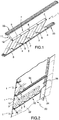
- Fig. 1 is schematically illustrated the basic details of an inwards folding prevention device 1 for a vertically foldable door, according to the present invention.
- the device comprises a plurality of ribs 3 that are arranged in parallel and at a distance from each other.
- the ribs 3 are connected with each other by means of a first connection arrangement comprising a bottom strip 5.
- Each rib 3 is articulately connected to the common bottom strip 5 by a lower end of the rib.
- the rib is articulately connected by means of an articulation 6 such as a hinge device or similar that is secured to the bottom strip 5.
- the ribs 3 are secured to the bottom strip 5 at regular intervals.
- the inwards folding prevention device 1 comprises a set of five ribs 3, but any number of ribs can be foreseen, depending on the size of the door.
- the bottom strip 5 is configured to be mounted on a lower horizontal support member 30 forming part of the door, as will be explained later.
- the inwards folding prevention device 1 further comprises a second connection arrangement 7 for connection of the ribs 3 to each other.
- this second connection arrangement 7 comprises an elongated connection member 9 to which the upper end of each rib 3 is connected.
- Each rib 3 may e.g. be articulately connected by means of an articulation 8 such as a hinge device or similar that is secured to the connection member 9.
- the ribs 3 are secured to the connection member 9 with the same intervals as to the bottom strip 5.
- the inwards folding prevention device 1 further comprises a lifting means 11, which in the illustrated example comprises a lifting member 12 of an elongated form.
- the lifting member 12 is connected at one lower end to one of the ribs 3, namely the first rib in the formed set of ribs, e.g. movably or articulately connected for example by a hinge device.
- a hinge device At the other, upper end it is connected, e.g. movably or articulately connected, for example by a hinge device, to a horizontal upper support member 32 forming part of the door, as will be explained later.
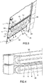
- FIG. 2 is schematically shown an embodiment of a vertically foldable door 20 according to the present invention.
- the door comprises two foldable door leaves 22, 24 that are arranged in parallel and at a distance from each other. Thereby is formed an interspace 26 between the two door leaves.
- the door leaves will be referred to as the first door leaf 22 and the second door leaf 24.
- intermediate support members in the form of a lower support member 30 and an upper support member 32.
- an inwards folding prevention device 1 of the type that has been described above.
- the inwards folding prevention device 1 is illustrated in its unfolded position corresponding to an unfolded, lowered and thereby closed door.
- the intermediate support member 32 forms the upper support member to which the lifting member 12 is articulately or at least movably connected.
- the intermediate support member 30 forms the lower support member on which the bottom strip 5 is mounted, and preferably secured.
- Fig. 3 is shown a second embodiment.
- the ribs 13 are interconnected at their upper ends by means of the connection member 9. Since Fig. 2 shows the unfolded position of the door, it can be seen that the ribs only extend up to approximately half the distance between the support members 30, 32. In the embodiment in Fig. 3 , the ribs 13 have been extended past the connection point with the connection member 9, and can be seen to extend over almost the entire distance between the two support members 30, 32. The ribs 13 are interconnected by the connection member 9 at about midpoint of the respective rib.
- Figs. 2 and 3 the door is illustrated in a lowered, unfolded position, and with the inwards folding prevention device likewise in an unfolded position, in order to prevent that sideways forces from e.g. hard winds will press sections of one of the door leaves into the interspace of the door.
- the door is opened, i.e. when the door is lifted up, this is made by lifting the bottom support member of the door, and successively the intermediate members are lifted upwards, one after the other, and successively stacked one on top of the other.
- the lower support member 30, shown in Figs. 2 and 3 will be lifted upwards, or rather pushed upwards by the underlying support member.
- ribs 3, 13 will then start to fold down as the lower support member 30 is moved upwards, until they are lying flat against the lower support member 30, and also flat against the upper support member 32 which will then be forced to move upwards.
- Fig. 4 are illustrated details of the door 20 in a folded position. It can be seen how two support members 30, 32 have been stacked one on top of the other with ribs 3 folded down between them. In this figure is also seen the folded lifting member 12, the hinge 6 where the rib 3 is connected to the bottom strip 5, as well as the bottom strip 5.
- the distance between the attachment points on the bottom strip 5 of two neighbouring ribs 3 is at least as long as the length of the rib 3 that is to be folded down in that space, as shown in Fig. 2 .
- all of the ribs 3, 13, bottom strip 5 and connection member 9 are made of a relatively stiff material, such that they can all be lifted up as one unit and without being deformed, when a lifting force is applied via the lifting member 12 when the door leaves are unfolded.
- the ribs 3, 13 are generally flat strips of an elongated form and may have a certain width, which helps to provide stiffness. They are preferably identical, and stackable.
- the ribs 3, 13 may have a width that corresponds to the width of the support members 30, 32 in order to fill out the space between the door leaves 22, 23 as much as possible and this will also enhance their function of preventing inwards folding of parts of the door leaves.
- the lifting member 12 preferably has the same shape and width as the ribs 3, 13, but may be of a slightly flexible material.
- the lifting member 12 has a length that corresponds to the length of the rib 3, 13 to which it is connected, measured between two points, of which the first point is the connection point between the rib 3, 13 and the lifting member 12 and the second point is the point where the rib 3, 13 is articulately connected to the lower support member 30.
- the lifting member 12 may for example be some type of string or cord that is simply movably attached to a rib and to the upper support member.
- connection member 9 which has been illustrated in the examples as being similar to the ribs and to which the ribs have been described as being articulately connected, could also alternatively be configured as some type of string or cord that is movably attached to a ribs.
- the inwards folding prevention device 1 has been described as being mounted between and connected to two intermediate support members.
- the device may just as well be mounted between a bottom support member of the door and the following intermediate member, or between a top support member and the following intermediate support member.
- anyone of the top support member and any intermediate support member can form the upper support member
- anyone of any intermediate support member and the bottom support member can form the lower support member.
- a door can be provided with a plurality of inwards folding prevention devices arranged at different levels in the vertical direction of the door. This is also schematically shown in Figs. 2 and 3 .
- inwards folding prevention devices 1 are located at intervals in the vertical direction of the door, such that the space formed between two intermediate members on the level immediately above one inwards folding prevention device does not include any inwards folding prevention device. Naturally, there can be more than one such empty level.
- the described inwards folding prevention device 1 may constitute one unit that can be extended in the horizontal direction of the door 20 by connecting it with another inward folding prevention device of the same construction forming an extension unit.
- This extension unit would not have to have any lifting member.
- more than one extension unit may be connected in a row.
Landscapes
- Engineering & Computer Science (AREA)
- Structural Engineering (AREA)
- Civil Engineering (AREA)
- Architecture (AREA)
- Extensible Doors And Revolving Doors (AREA)
Claims (12)
- Vertikal faltbare Tür (20), wobei die Tür zwei faltbare Türblätter (22, 24) umfasst, die parallel und in einem Abstand zueinander angeordnet sind und dadurch ein Zwischenraum (26) zwischen den beiden Türblättern (22, 24) bilden, und wobei die Türblätter aus einem flexiblem Material hergestellt sind, und die Tür (20) ausgelegt ist, um in einem Hebevorgang angehoben zu werden, bei dem die Türblätter (22, 24) gefaltet werden, und um in einem Senkvorgang gesenkt zu werden, bei dem die Türblätter entfaltet werden, wobei die Tür ferner mindestens zwei längliche horizontale Stützelemente (30, 32) zur Unterstützung der Türblätter (22, 24) und eine Vorrichtung zum Verhindern eines Faltens nach innen (1) umfasst, die im Zwischenraum (26) zwischen den beiden Türblättern (22, 24) derart angeordnet ist, dass während des Hebevorgangs ein Falten nach innen zumindest eines Teils von mindestens einem der Türblätter (22, 24) in den Zwischenraum (26) verhindert wird, dadurch gekennzeichnet, dass
die Vorrichtung zum Verhindern eines Faltens nach innen (1) eine Mehrzahl von Rippen (3) umfasst, die parallel zueinander angeordnet sind und über eine erste Verbindungsvorrichtung (5) und über eine zweite Verbindungsvorrichtung (7) miteinander verbunden sind, und von den Rippen (3) mindestens eine Rippe mittels der Stützelemente (30, 32) mit mindestens einem Türblatt (22, 24) verbunden ist, welche Rippen (3) angeordnet sind, um eine horizontale Position einzunehmen, wenn sich die Türblätter (22, 24) in einer gefalteten Position befinden, und um angehoben zu werden, wenn die Türblätter (22, 24) während des Senkvorgangs entfaltet werden,
wobei die Stützelemente (30, 32) in einem Abstand zueinander angeordnet sind, und welche Stützelemente (30, 32) mit den Türblättern verbunden sind, und wobei jede Rippe (3) an einem unteren Ende davon mittels der ersten Verbindungsvorrichtung (5) mit einem unteren Stützelement (30) der mindestens zwei Stützelemente (30, 32) gelenkig verbunden ist, und
wobei die Mehrzahl von Rippen (3) eine Breite aufweist, die einer Breite der Stützelemente (30, 32) entspricht. - Vertikal faltbare Tür nach Anspruch 1, wobei die Rippen (3) mit der zweiten Verbindungsvorrichtung (7) beweglich verbunden sind.
- Vertikal faltbare Tür nach einem der Ansprüche 1-2, wobei die Vorrichtung zum Verhindern eines Faltens nach innen (1) ein Hebemittel (11) zum Heben der Rippen umfasst, wenn die Türblätter während des Senkvorgangs entfaltet werden.
- Vertikal faltbare Tür nach Anspruch 3, wobei das Hebemittel (11) ein mit mindestens einer der Rippen (3) verbundenes Hebeelement (12) umfasst.
- Vertikal faltbare Tür nach einem der Ansprüche 1-4, wobei jede Rippe (3) an einem unteren Ende mit einem gemeinsamen Bodenstreifen (5) gelenkig verbunden ist, der einen Teil der ersten Verbindungsvorrichtung bildet, welcher gemeinsamer Bodenstreifen an einem unteren Stützelement (30) der mindestens zwei Stützelemente (30, 32) montiert ist.
- Vertikal faltbare Tür nach einem der Ansprüche 4-5, wobei das Hebeelement (12) mit einem oberen Stützelement (32) der mindestens zwei Stützelemente (30, 32) verbunden ist.
- Vertikal faltbare Tür nach Anspruch 6, wobei das Hebeelement (12) eine Länge aufweist, die einer Länge derjenigen Rippe (3) entspricht, mit der es verbunden ist, wie gemessen zwischen zwei Punkten auf der Rippe, von denen der erste Punkt der Verbindungspunkt zwischen der Rippe (3) und dem Hebeelement (12) ist, und der zweite Punkt der Punkt ist, wo die Rippe (3) mit dem unteren Stützelement (30) gelenkig verbunden ist.
- Vertikal faltbare Tür nach einem der Ansprüche 1-7, wobei die Rippen (3) an ihren jeweiligen oberen Enden mit der zweiten Verbindungsvorrichtung (7) verbunden sind.
- Vertikal faltbare Tür nach einem der Ansprüche 1-8, wobei die Rippen (3) eine derartige Länge aufweist, dass sich die Rippen an ihren jeweiligen Verbindungspunkten mit der zweiten Verbindungsvorrichtung (7) vorbei, in eine Richtung gegen ein benachbartes oberes Stützelement (32) erstrecken, wenn sich die Tür in einem entfalteten Zustand befindet.
- Vertikal faltbare Tür nach einem der Ansprüche 1-9, wobei die mindestens zwei länglichen horizontalen Stützelemente (30, 32) mindestens zwei der folgenden umfasst:- ein oberes Stützelement zur Unterstützung eines jeweiligen oberen Endes der beiden Türblätter (22, 24) in einem Abstand zueinander,- ein unteres Stützelement zur Unterstützung eines jeweiligen unteren Endes der beiden Türblätter (22, 24) in einem Abstand zueinander,- mindestens ein zwischen dem oberen Stützelement und dem unteren Stützelement angeordnetes Zwischenstützelement,wobei ein beliebiges des oberen Stützelements und eines beliebigen Zwischenstützelements das obere Stützelement (32) bilden kann, und ein beliebiges eines beliebigen Zwischenstützelements und des unteren Stützelements das untere Stützelement (30) bilden kann.
- Vertikal faltbare Tür nach einem der vorgehenden Ansprüche, wobei sie eine Mehrzahl von Vorrichtungen zum Verhindern eines Faltens nach innen (1) nach einem der vorgehenden Ansprüche umfasst, wobei die Vorrichtungen auf verschiedenen Ebenen in der Vertikalrichtung der Tür angeordnet sind.
- Vertikal faltbare Tür nach einem der vorgehenden Ansprüche, wobei die Vorrichtung zum Verhindern eines Faltens nach innen (1) eine Einheit bildet, und wobei sie in der Horizontalrichtung der Tür dadurch verlängert ist, dass sie mit einer Verlängerungseinheit verbunden ist, die aus einer anderen Vorrichtung zum Verhindern eines Faltens nach innen der gleichen Konstruktion gebildet ist, mit der Ausnahme, dass die kein Hebeelement aufweist.
Priority Applications (1)
| Application Number | Priority Date | Filing Date | Title |
|---|---|---|---|
| EP15191043.7A EP3159472B1 (de) | 2015-10-22 | 2015-10-22 | Vertikal faltbare tür |
Applications Claiming Priority (1)
| Application Number | Priority Date | Filing Date | Title |
|---|---|---|---|
| EP15191043.7A EP3159472B1 (de) | 2015-10-22 | 2015-10-22 | Vertikal faltbare tür |
Publications (2)
| Publication Number | Publication Date |
|---|---|
| EP3159472A1 EP3159472A1 (de) | 2017-04-26 |
| EP3159472B1 true EP3159472B1 (de) | 2019-09-25 |
Family
ID=54360061
Family Applications (1)
| Application Number | Title | Priority Date | Filing Date |
|---|---|---|---|
| EP15191043.7A Active EP3159472B1 (de) | 2015-10-22 | 2015-10-22 | Vertikal faltbare tür |
Country Status (1)
| Country | Link |
|---|---|
| EP (1) | EP3159472B1 (de) |
Family Cites Families (5)
| Publication number | Priority date | Publication date | Assignee | Title |
|---|---|---|---|---|
| ES2126429B1 (es) * | 1995-04-19 | 1999-11-16 | Portes Bisbal S A | Puerta ligera de seguridad de uso industrial interno. |
| SE506390C2 (sv) * | 1996-05-07 | 1997-12-08 | Megadoor Ab | Anordning och förfarande vid manövrering av ett objekt t ex port |
| FR2769944B1 (fr) * | 1997-10-20 | 2000-01-21 | Bernard Simon | Porte isotherme a double soufflet |
| EP2284351B1 (de) * | 2008-05-02 | 2016-03-30 | Amiserru, S.L. | Schnell öffnende tür mit zwei vorhängen |
| KR101025784B1 (ko) * | 2008-10-16 | 2011-04-04 | 곽병철 | 출입구 개폐용 문의 승강바 |
-
2015
- 2015-10-22 EP EP15191043.7A patent/EP3159472B1/de active Active
Non-Patent Citations (1)
| Title |
|---|
| None * |
Also Published As
| Publication number | Publication date |
|---|---|
| EP3159472A1 (de) | 2017-04-26 |
Similar Documents
| Publication | Publication Date | Title |
|---|---|---|
| EP4139538B1 (de) | Terrassenüberdachung | |
| EP2122088B1 (de) | Schirmartige abdeckungsstruktur mit rippen in form von parallelogramm-verknüpfungen | |
| US5582226A (en) | Venetian blind | |
| US20180106031A1 (en) | Collapsible Modular Building | |
| KR100977581B1 (ko) | 비닐하우스용 환기장치 | |
| KR100925749B1 (ko) | 다단으로 승강절첩 및 확개되는 출입구 개폐용 문 | |
| US9523212B2 (en) | Variable height telescoping lattice tower | |
| US7637275B2 (en) | Telescopic post for a folding structure and one such structure | |
| EP3159472B1 (de) | Vertikal faltbare tür | |
| EP1475508B1 (de) | Vertikal beweglicheTrennwand | |
| US7261137B2 (en) | Retractable blind assembly | |
| EP3309337B1 (de) | Aufwärts bewegbare tür | |
| US919361A (en) | Outing-cottage. | |
| KR100925748B1 (ko) | 출입구 개폐용 문의 가요성 시트 절첩안내장치 | |
| KR101114818B1 (ko) | 출입구 개폐용 문의 가요성 시트 절첩 안내장치 | |
| KR100577616B1 (ko) | 셔터조립체 | |
| KR200498618Y1 (ko) | 출입문 주름 방충 시스템용 합성수지 방충 바의 이음 구조 | |
| ITGE940041A1 (it) | Inferriata apribile predisposta per ricevere la zanzariera per vani di serramenti esterni. | |
| EP3268552B1 (de) | Gewächshaus | |
| WO1983003861A1 (en) | Arrangement for a collapsible frame and similar structures | |
| KR100949089B1 (ko) | 출입구 개폐용 문의 승강바 휨 방지장치 | |
| EP2400105B1 (de) | Insektenschutznetz für bogenförmige Öffnungen | |
| EP1413706A2 (de) | Betätigungsvorrichtung für Jalousien | |
| JPH0531196Y2 (de) | ||
| KR200340806Y1 (ko) | 셔터조립체 |
Legal Events
| Date | Code | Title | Description |
|---|---|---|---|
| PUAI | Public reference made under article 153(3) epc to a published international application that has entered the european phase |
Free format text: ORIGINAL CODE: 0009012 |
|
| STAA | Information on the status of an ep patent application or granted ep patent |
Free format text: STATUS: THE APPLICATION HAS BEEN PUBLISHED |
|
| AK | Designated contracting states |
Kind code of ref document: A1 Designated state(s): AL AT BE BG CH CY CZ DE DK EE ES FI FR GB GR HR HU IE IS IT LI LT LU LV MC MK MT NL NO PL PT RO RS SE SI SK SM TR |
|
| AX | Request for extension of the european patent |
Extension state: BA ME |
|
| STAA | Information on the status of an ep patent application or granted ep patent |
Free format text: STATUS: REQUEST FOR EXAMINATION WAS MADE |
|
| 17P | Request for examination filed |
Effective date: 20171004 |
|
| RBV | Designated contracting states (corrected) |
Designated state(s): AL AT BE BG CH CY CZ DE DK EE ES FI FR GB GR HR HU IE IS IT LI LT LU LV MC MK MT NL NO PL PT RO RS SE SI SK SM TR |
|
| STAA | Information on the status of an ep patent application or granted ep patent |
Free format text: STATUS: EXAMINATION IS IN PROGRESS |
|
| 17Q | First examination report despatched |
Effective date: 20180307 |
|
| GRAP | Despatch of communication of intention to grant a patent |
Free format text: ORIGINAL CODE: EPIDOSNIGR1 |
|
| STAA | Information on the status of an ep patent application or granted ep patent |
Free format text: STATUS: GRANT OF PATENT IS INTENDED |
|
| INTG | Intention to grant announced |
Effective date: 20190510 |
|
| GRAS | Grant fee paid |
Free format text: ORIGINAL CODE: EPIDOSNIGR3 |
|
| GRAA | (expected) grant |
Free format text: ORIGINAL CODE: 0009210 |
|
| STAA | Information on the status of an ep patent application or granted ep patent |
Free format text: STATUS: THE PATENT HAS BEEN GRANTED |
|
| AK | Designated contracting states |
Kind code of ref document: B1 Designated state(s): AL AT BE BG CH CY CZ DE DK EE ES FI FR GB GR HR HU IE IS IT LI LT LU LV MC MK MT NL NO PL PT RO RS SE SI SK SM TR |
|
| REG | Reference to a national code |
Ref country code: GB Ref legal event code: FG4D |
|
| REG | Reference to a national code |
Ref country code: CH Ref legal event code: EP |
|
| REG | Reference to a national code |
Ref country code: AT Ref legal event code: REF Ref document number: 1183986 Country of ref document: AT Kind code of ref document: T Effective date: 20191015 |
|
| REG | Reference to a national code |
Ref country code: IE Ref legal event code: FG4D |
|
| REG | Reference to a national code |
Ref country code: DE Ref legal event code: R096 Ref document number: 602015038582 Country of ref document: DE |
|
| REG | Reference to a national code |
Ref country code: NL Ref legal event code: MP Effective date: 20190925 |
|
| PG25 | Lapsed in a contracting state [announced via postgrant information from national office to epo] |
Ref country code: FI Free format text: LAPSE BECAUSE OF FAILURE TO SUBMIT A TRANSLATION OF THE DESCRIPTION OR TO PAY THE FEE WITHIN THE PRESCRIBED TIME-LIMIT Effective date: 20190925 Ref country code: SE Free format text: LAPSE BECAUSE OF FAILURE TO SUBMIT A TRANSLATION OF THE DESCRIPTION OR TO PAY THE FEE WITHIN THE PRESCRIBED TIME-LIMIT Effective date: 20190925 Ref country code: BG Free format text: LAPSE BECAUSE OF FAILURE TO SUBMIT A TRANSLATION OF THE DESCRIPTION OR TO PAY THE FEE WITHIN THE PRESCRIBED TIME-LIMIT Effective date: 20191225 Ref country code: HR Free format text: LAPSE BECAUSE OF FAILURE TO SUBMIT A TRANSLATION OF THE DESCRIPTION OR TO PAY THE FEE WITHIN THE PRESCRIBED TIME-LIMIT Effective date: 20190925 Ref country code: NO Free format text: LAPSE BECAUSE OF FAILURE TO SUBMIT A TRANSLATION OF THE DESCRIPTION OR TO PAY THE FEE WITHIN THE PRESCRIBED TIME-LIMIT Effective date: 20191225 Ref country code: LT Free format text: LAPSE BECAUSE OF FAILURE TO SUBMIT A TRANSLATION OF THE DESCRIPTION OR TO PAY THE FEE WITHIN THE PRESCRIBED TIME-LIMIT Effective date: 20190925 |
|
| REG | Reference to a national code |
Ref country code: LT Ref legal event code: MG4D |
|
| PG25 | Lapsed in a contracting state [announced via postgrant information from national office to epo] |
Ref country code: RS Free format text: LAPSE BECAUSE OF FAILURE TO SUBMIT A TRANSLATION OF THE DESCRIPTION OR TO PAY THE FEE WITHIN THE PRESCRIBED TIME-LIMIT Effective date: 20190925 Ref country code: LV Free format text: LAPSE BECAUSE OF FAILURE TO SUBMIT A TRANSLATION OF THE DESCRIPTION OR TO PAY THE FEE WITHIN THE PRESCRIBED TIME-LIMIT Effective date: 20190925 Ref country code: GR Free format text: LAPSE BECAUSE OF FAILURE TO SUBMIT A TRANSLATION OF THE DESCRIPTION OR TO PAY THE FEE WITHIN THE PRESCRIBED TIME-LIMIT Effective date: 20191226 |
|
| REG | Reference to a national code |
Ref country code: AT Ref legal event code: MK05 Ref document number: 1183986 Country of ref document: AT Kind code of ref document: T Effective date: 20190925 |
|
| PG25 | Lapsed in a contracting state [announced via postgrant information from national office to epo] |
Ref country code: EE Free format text: LAPSE BECAUSE OF FAILURE TO SUBMIT A TRANSLATION OF THE DESCRIPTION OR TO PAY THE FEE WITHIN THE PRESCRIBED TIME-LIMIT Effective date: 20190925 Ref country code: IT Free format text: LAPSE BECAUSE OF FAILURE TO SUBMIT A TRANSLATION OF THE DESCRIPTION OR TO PAY THE FEE WITHIN THE PRESCRIBED TIME-LIMIT Effective date: 20190925 Ref country code: ES Free format text: LAPSE BECAUSE OF FAILURE TO SUBMIT A TRANSLATION OF THE DESCRIPTION OR TO PAY THE FEE WITHIN THE PRESCRIBED TIME-LIMIT Effective date: 20190925 Ref country code: AL Free format text: LAPSE BECAUSE OF FAILURE TO SUBMIT A TRANSLATION OF THE DESCRIPTION OR TO PAY THE FEE WITHIN THE PRESCRIBED TIME-LIMIT Effective date: 20190925 Ref country code: AT Free format text: LAPSE BECAUSE OF FAILURE TO SUBMIT A TRANSLATION OF THE DESCRIPTION OR TO PAY THE FEE WITHIN THE PRESCRIBED TIME-LIMIT Effective date: 20190925 Ref country code: NL Free format text: LAPSE BECAUSE OF FAILURE TO SUBMIT A TRANSLATION OF THE DESCRIPTION OR TO PAY THE FEE WITHIN THE PRESCRIBED TIME-LIMIT Effective date: 20190925 Ref country code: PL Free format text: LAPSE BECAUSE OF FAILURE TO SUBMIT A TRANSLATION OF THE DESCRIPTION OR TO PAY THE FEE WITHIN THE PRESCRIBED TIME-LIMIT Effective date: 20190925 Ref country code: RO Free format text: LAPSE BECAUSE OF FAILURE TO SUBMIT A TRANSLATION OF THE DESCRIPTION OR TO PAY THE FEE WITHIN THE PRESCRIBED TIME-LIMIT Effective date: 20190925 Ref country code: PT Free format text: LAPSE BECAUSE OF FAILURE TO SUBMIT A TRANSLATION OF THE DESCRIPTION OR TO PAY THE FEE WITHIN THE PRESCRIBED TIME-LIMIT Effective date: 20200127 |
|
| PG25 | Lapsed in a contracting state [announced via postgrant information from national office to epo] |
Ref country code: SK Free format text: LAPSE BECAUSE OF FAILURE TO SUBMIT A TRANSLATION OF THE DESCRIPTION OR TO PAY THE FEE WITHIN THE PRESCRIBED TIME-LIMIT Effective date: 20190925 Ref country code: CZ Free format text: LAPSE BECAUSE OF FAILURE TO SUBMIT A TRANSLATION OF THE DESCRIPTION OR TO PAY THE FEE WITHIN THE PRESCRIBED TIME-LIMIT Effective date: 20190925 Ref country code: IS Free format text: LAPSE BECAUSE OF FAILURE TO SUBMIT A TRANSLATION OF THE DESCRIPTION OR TO PAY THE FEE WITHIN THE PRESCRIBED TIME-LIMIT Effective date: 20200224 Ref country code: SM Free format text: LAPSE BECAUSE OF FAILURE TO SUBMIT A TRANSLATION OF THE DESCRIPTION OR TO PAY THE FEE WITHIN THE PRESCRIBED TIME-LIMIT Effective date: 20190925 |
|
| REG | Reference to a national code |
Ref country code: CH Ref legal event code: PL |
|
| REG | Reference to a national code |
Ref country code: DE Ref legal event code: R097 Ref document number: 602015038582 Country of ref document: DE |
|
| PG2D | Information on lapse in contracting state deleted |
Ref country code: IS |
|
| PG25 | Lapsed in a contracting state [announced via postgrant information from national office to epo] |
Ref country code: DK Free format text: LAPSE BECAUSE OF FAILURE TO SUBMIT A TRANSLATION OF THE DESCRIPTION OR TO PAY THE FEE WITHIN THE PRESCRIBED TIME-LIMIT Effective date: 20190925 Ref country code: LU Free format text: LAPSE BECAUSE OF NON-PAYMENT OF DUE FEES Effective date: 20191022 Ref country code: LI Free format text: LAPSE BECAUSE OF NON-PAYMENT OF DUE FEES Effective date: 20191031 Ref country code: CH Free format text: LAPSE BECAUSE OF NON-PAYMENT OF DUE FEES Effective date: 20191031 Ref country code: IS Free format text: LAPSE BECAUSE OF FAILURE TO SUBMIT A TRANSLATION OF THE DESCRIPTION OR TO PAY THE FEE WITHIN THE PRESCRIBED TIME-LIMIT Effective date: 20200126 |
|
| PLBE | No opposition filed within time limit |
Free format text: ORIGINAL CODE: 0009261 |
|
| STAA | Information on the status of an ep patent application or granted ep patent |
Free format text: STATUS: NO OPPOSITION FILED WITHIN TIME LIMIT |
|
| REG | Reference to a national code |
Ref country code: BE Ref legal event code: MM Effective date: 20191031 |
|
| PG25 | Lapsed in a contracting state [announced via postgrant information from national office to epo] |
Ref country code: MC Free format text: LAPSE BECAUSE OF FAILURE TO SUBMIT A TRANSLATION OF THE DESCRIPTION OR TO PAY THE FEE WITHIN THE PRESCRIBED TIME-LIMIT Effective date: 20190925 Ref country code: BE Free format text: LAPSE BECAUSE OF NON-PAYMENT OF DUE FEES Effective date: 20191031 |
|
| 26N | No opposition filed |
Effective date: 20200626 |
|
| GBPC | Gb: european patent ceased through non-payment of renewal fee |
Effective date: 20191225 |
|
| PG25 | Lapsed in a contracting state [announced via postgrant information from national office to epo] |
Ref country code: GB Free format text: LAPSE BECAUSE OF NON-PAYMENT OF DUE FEES Effective date: 20191225 Ref country code: IE Free format text: LAPSE BECAUSE OF NON-PAYMENT OF DUE FEES Effective date: 20191022 |
|
| PG25 | Lapsed in a contracting state [announced via postgrant information from national office to epo] |
Ref country code: SI Free format text: LAPSE BECAUSE OF FAILURE TO SUBMIT A TRANSLATION OF THE DESCRIPTION OR TO PAY THE FEE WITHIN THE PRESCRIBED TIME-LIMIT Effective date: 20190925 |
|
| PG25 | Lapsed in a contracting state [announced via postgrant information from national office to epo] |
Ref country code: CY Free format text: LAPSE BECAUSE OF FAILURE TO SUBMIT A TRANSLATION OF THE DESCRIPTION OR TO PAY THE FEE WITHIN THE PRESCRIBED TIME-LIMIT Effective date: 20190925 |
|
| PG25 | Lapsed in a contracting state [announced via postgrant information from national office to epo] |
Ref country code: HU Free format text: LAPSE BECAUSE OF FAILURE TO SUBMIT A TRANSLATION OF THE DESCRIPTION OR TO PAY THE FEE WITHIN THE PRESCRIBED TIME-LIMIT; INVALID AB INITIO Effective date: 20151022 Ref country code: MT Free format text: LAPSE BECAUSE OF FAILURE TO SUBMIT A TRANSLATION OF THE DESCRIPTION OR TO PAY THE FEE WITHIN THE PRESCRIBED TIME-LIMIT Effective date: 20190925 |
|
| PG25 | Lapsed in a contracting state [announced via postgrant information from national office to epo] |
Ref country code: TR Free format text: LAPSE BECAUSE OF FAILURE TO SUBMIT A TRANSLATION OF THE DESCRIPTION OR TO PAY THE FEE WITHIN THE PRESCRIBED TIME-LIMIT Effective date: 20190925 |
|
| PG25 | Lapsed in a contracting state [announced via postgrant information from national office to epo] |
Ref country code: MK Free format text: LAPSE BECAUSE OF FAILURE TO SUBMIT A TRANSLATION OF THE DESCRIPTION OR TO PAY THE FEE WITHIN THE PRESCRIBED TIME-LIMIT Effective date: 20190925 |
|
| P01 | Opt-out of the competence of the unified patent court (upc) registered |
Effective date: 20230530 |
|
| PGFP | Annual fee paid to national office [announced via postgrant information from national office to epo] |
Ref country code: FR Payment date: 20250922 Year of fee payment: 11 |
|
| PGFP | Annual fee paid to national office [announced via postgrant information from national office to epo] |
Ref country code: DE Payment date: 20250910 Year of fee payment: 11 |