EP3159463B1 - Anti-amok cylinder - Google Patents
Anti-amok cylinder Download PDFInfo
- Publication number
- EP3159463B1 EP3159463B1 EP16193677.8A EP16193677A EP3159463B1 EP 3159463 B1 EP3159463 B1 EP 3159463B1 EP 16193677 A EP16193677 A EP 16193677A EP 3159463 B1 EP3159463 B1 EP 3159463B1
- Authority
- EP
- European Patent Office
- Prior art keywords
- grip
- amok
- locking member
- closing
- camshaft
- Prior art date
- Legal status (The legal status is an assumption and is not a legal conclusion. Google has not performed a legal analysis and makes no representation as to the accuracy of the status listed.)
- Active
Links
Images



Classifications
-
- E—FIXED CONSTRUCTIONS
- E05—LOCKS; KEYS; WINDOW OR DOOR FITTINGS; SAFES
- E05B—LOCKS; ACCESSORIES THEREFOR; HANDCUFFS
- E05B65/00—Locks or fastenings for special use
- E05B65/10—Locks or fastenings for special use for panic or emergency doors
- E05B65/1086—Locks with panic function, e.g. allowing opening from the inside without a ley even when locked from the outside
-
- E—FIXED CONSTRUCTIONS
- E05—LOCKS; KEYS; WINDOW OR DOOR FITTINGS; SAFES
- E05B—LOCKS; ACCESSORIES THEREFOR; HANDCUFFS
- E05B17/00—Accessories in connection with locks
- E05B17/04—Devices for coupling the turning cylinder of a single or a double cylinder lock with the bolt operating member
- E05B17/044—Clutches, disengageable couplings
- E05B17/045—Clutches, disengageable couplings for keeping the rotor disconnected from the bolt actuating member, when being turned, e.g. forcefully, without the proper key
-
- E—FIXED CONSTRUCTIONS
- E05—LOCKS; KEYS; WINDOW OR DOOR FITTINGS; SAFES
- E05B—LOCKS; ACCESSORIES THEREFOR; HANDCUFFS
- E05B47/00—Operating or controlling locks or other fastening devices by electric or magnetic means
- E05B47/06—Controlling mechanically-operated bolts by electro-magnetically-operated detents
- E05B47/0611—Cylinder locks with electromagnetic control
- E05B47/0615—Cylinder locks with electromagnetic control operated by handles, e.g. by knobs
-
- E—FIXED CONSTRUCTIONS
- E05—LOCKS; KEYS; WINDOW OR DOOR FITTINGS; SAFES
- E05B—LOCKS; ACCESSORIES THEREFOR; HANDCUFFS
- E05B47/00—Operating or controlling locks or other fastening devices by electric or magnetic means
- E05B47/06—Controlling mechanically-operated bolts by electro-magnetically-operated detents
- E05B47/0611—Cylinder locks with electromagnetic control
- E05B47/0638—Cylinder locks with electromagnetic control by disconnecting the rotor
-
- E—FIXED CONSTRUCTIONS
- E05—LOCKS; KEYS; WINDOW OR DOOR FITTINGS; SAFES
- E05B—LOCKS; ACCESSORIES THEREFOR; HANDCUFFS
- E05B9/00—Lock casings or latch-mechanism casings ; Fastening locks or fasteners or parts thereof to the wing
- E05B9/10—Coupling devices for the two halves of double cylinder locks, e.g. devices for coupling the rotor with the locking cam
- E05B9/105—Coupling devices for the two halves of double cylinder locks, e.g. devices for coupling the rotor with the locking cam including disengagement means, e.g. opening from one side being still possible even if the key is inserted from the other side
-
- E—FIXED CONSTRUCTIONS
- E05—LOCKS; KEYS; WINDOW OR DOOR FITTINGS; SAFES
- E05B—LOCKS; ACCESSORIES THEREFOR; HANDCUFFS
- E05B9/00—Lock casings or latch-mechanism casings ; Fastening locks or fasteners or parts thereof to the wing
- E05B9/04—Casings of cylinder locks
- E05B2009/046—Cylinder locks operated by knobs or handles
Definitions
- the invention is directed to an anti-amok cylinder comprising an inner grip and an outer grip wherein the inner grip is connected to a closing lug and a coupling device is provided which is designed to connect the outer grip to the closing lug when a closing authorization is present.
- Anti-amok cylinders are known from public prior use.
- the anti-amok function makes it possible for someone to withdraw into a room closed by a door which has an anti-amok cylinder without a person without closing authorization getting access to the room from outside but one can always actuate the anti-amok cylinder without closing authorization from inside and can leave the room.
- the inner grip of an anti-amok cylinder is connected to the closing lug at any time wherein only the outer grip can be connected to the closing lug by presenting a closing authorization.
- the closing authorization can be proved as key, as key card or as transmitter transmitting a signal indicating the closing authorization.
- the outer grip is not connected to the closing lug so that an actuation of the anti-amok cylinder and an opening of the door and thus an access to the room (protected from amok) is not possible.
- An example of an anti-amok cylinder is also known from EP 1 719 861 S2 . Handles for such cylinders are known from DE 10 2004 009 992 A1 .
- Anti-amok cylinders are used in all cases in which on the one side a simple access to a plurality of rooms, for instance through a common corridor, and on the other side a high safety necessity exists. Especially school buildings are progressively provided with anti-amok cylinders.
- a disadvantage with regard to the use of anti-amok cylinders consists in the fact that the anti-amok function can be misused in a manner that a person proving the closing authorization can be prevented from entering a room secured by an anti-amok cylinder from outside by the fact that the inner grip is fixed by a person who is on the inner side of the room. Accordingly, the person on the outside of the room - in spite of a presented closing authorization - for entering the room is forced to apply a higher force than the force applied from inside concurrent with the closing lug in order to be able to enter the room - this is often not possible or only possible with very high effort.
- anti-amok cylinder with anti-barricade function examples are known from GB 2 334 546 A and GB 2 469 652 A in which the door can still be unlocked from the outside if necessary by operating the correct key.
- an anti-amok cylinder according to which a person having a closing authorization cannot be prevented from access to a room secured by an anti-amok cylinder.
- the inner grip is disengaged from the closing lug so that the door can be opened from outside even if the inner grip is fixed.
- the invention is especially suitable for the use in connection with doors closing rooms which are on principle accessible by persons presenting a closing authorization and where the persons with closing authorization shall not be prevented from access by manual action from inside.
- a special case of application is defined by schools in which the scholars could prevent the entering of the classroom by a teacher by fixing the inner grip up to now.
- the invention enables the teacher an undisturbed access to the classroom when he applies a higher force acting upon the closing lug than the force applied by keeping shut.
- an anti-amok cylinder comprising an inner grip and an outer grip wherein the inner grip is connected to a closing lug and a coupling device is provided which is designed for connecting the outer grip to the closing lug when a closing authorization is present.
- the inner knob and the closing lug are connected by means of a coupling which is designed for separating the connection between inner knob and closing lug when the closing authorization is present and for reaching a torque acting from the outer grip onto the closing lug wherein the coupling is designed as locking member coupling.
- the locking member coupling comprises a camshaft connected to the closing lug in a rotarily fixed manner, an inner grip sleeve connected to the inner grip in a rotarily fixed manner and a radially displaceably arranged locking member wherein the camshaft and the inner grip sleeve are supported in a rotary manner with respect to one another against the force of a spring.
- the locking member is received by a locking member recess formed in the inner grip sleeve in a first position supported against the cam of the camshaft and generates the connection between the inner grip and the closing lug.
- the locking member protrudes from the locking member recess into a second position interrupting the connection between the inner grip and the closing lug when the force of the spring has been overcome and the cam acting as abutment of the locking member has been rotated.
- the locking member is radially displaceably supported in an inner sleeve connected to the camshaft wherein the inner sleeve is rotatably supported partly against the camshaft and completely against the inner grip sleeve.
- the inner sleeve and the camshaft are connected by means of the spring and are rotatably supported against its force.
- the spring connects the inner sleeve to a coupling intermediate member which is connected to the camshaft in a rotarily fixed manner.
- the spring is formed as leg spring.
- a pressure spring can be used.
- the outer grip and/or the inner grip are formed as knob.
- the invention is advantageously used since in this case the effort necessary for overcoming the above-described hindrance by a person on the inner side is significantly reduced.
- the use of a key, of a key card or of a wirelessly transmitted radio signal is suitable as closing authorization.
- the anti-amok cylinder is designed as digital cylinder (electronic double knob cylinder).
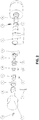
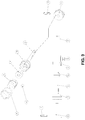
- Figure 1 shows a partly sectional side view of the anti-amok cylinder according to the invention designed in an especially preferred manner wherein figure 2 is an explosion view of the anti-amok cylinder of figure 1 .
- the anti-amok cylinder shows on its left side an outer grip 4 formed as outer knob 4 and on its right side an inner grip 7 formed as inner knob 7 which are connected to a closing cylinder arranged in a double cylinder housing 1.
- the anti-amok cylinder is formed as digital anti-amok cylinder.
- the outer knob 4 is coupled to the electronic core 3 so that, when the outer knob 4 and the electronic core 3 are coupled, the electronic core 3, the camshaft connected to the same in a rotarily fixed manner and the closing lug 2 connected to the camshaft 5 in a rotarily fixed manner are rotated by rotation of the outer knob 4 and a door (not shown) can be opened.
- a camshaft 5 is rotatably supported in the inner knob mandrel 10 of the inner knob 7 without being connected to the same.
- the inner knob 7 is secured at the inner knob mandrel 10 by means of the grooved pin 16 and the inner knob mandrel 10 is secured at the double cylinder housing 1 by means of the inner knob split-pin 11.
- the coupling intermediate member 14 is fixed at the camshaft 5 in a rotarily fixed manner by means of the split-pin 15 so that the coupling intermediate member 14 rotates together with the camshaft 5 when the same rotates.
- the coupling intermediate member 14 and the inner sleeve 6 receiving the coupling intermediate member 14 have a web-like stud extending into the same direction, respectively, which is engaged by a spring (not shown), especially formed as leg spring, wherein the spring holds the two webs - and thus the coupling intermediate member 14 and the inner sleeve 6 - in the same rotary position against the force of the spring.
- the inner sleeve 6, the coupling intermediate member 14 and the spring are received in the coupling member 13 arranged on the camshaft 5.
- the coupling member 13 forms a recess for receiving the spring and the webs formed by the coupling intermediate member 14 and the inner sleeve 6 wherein the recess limits the distortion of the coupling intermediate member 14 and the inner sleeve 6 with respect to another.
- the inner sleeve 6 has a recess radially extending through the sleeve wall in which the locking member 8 is radially displaceably supported.
- the locking member 8 is partly engaged in a locking member recess formed within the inner knob sleeve 9 which, in the shown example, is formed as longitudinal extending groove.
- the locking member 8 is maintained in position through the recess of the inner sleeve 6 in the locking member recess of the inner knob sleeve 9 by the cam of the camshaft 5.
- the inner knob sleeve 9 is connected to the inner knob mandrel 10 in a rotarily fixed manner and is furthermore connected to the inner knob 7 in a rotarily fixed manner, a rotation of the inner knob 7 causes a rotation of the inner knob sleeve 9 which lets co-rotate the inner sleeve 6 by means of the locking member 8 received in the locking member recess.
- the inner sleeve 6 rotates the closing lug 2 on account of the spring holding together the inner sleeve 6 and the coupling intermediate member 14 in the same rotary position and on account of the circumstance that the coupling intermediate member 14 is connected to the camshaft 5 in a rotarily fixed manner.
- the outer knob 4 does not co-rotate when the inner knob 7 is rotated for the case that a closing authorization is not present since the outer knob 4 is not connected to the electronic core 3 connected to the camshaft 6 in a rotarily fixed manner without closing authorization.
- a closing authorization is present, i. e. the outer knob 4 is connected to the camshaft 5 in a rotary manner by means of the electronic core 3, a rotation of the outer knob 4 alone results in a rotation not only of the closing lug 2 but also of the inner knob 7, and a rotation of the inner knob 4 alone results in a rotation not only of the closing lug 2 but also of the outer knob.
- the inner knob sleeve 9 the inner knob mandrel 10 and the inner knob 7 connected thereto can be twisted with respect to the inner sleeve 6 and the camshaft 2 without having effects on the closing lug 2 actuated by the outer knob 2.
- the force to be maximally applied for a closing process on the side of the outer knob 4 is determined by the spring constant.
- Figure 3 shows an explosion view of the members forming the locking member coupling of the anti-amok cylinder of figure 1 .
- the cam of the camshaft 5 and the longitudinally extending locking member recesses in the inner knob sleeve 9 can be clearly recognized.
- the cam, the locking member 8 and the locking member recess are formed in such a manner that the locking member 8 is tightly pressed into the locking member recess by the cam on the one side and the locking member 8 can slide out from the locking member recess without jamming on the other side.
- the cam is especially wedge-shaped with inclined side surfaces which allow a releasing of the cam from the locking member 8 and an approaching of the cam to the locking member 8.
- the locking member recess is formed as groove with inclined side surfaces enabling sliding out of the interlocking member 8 which is also wedge-shaped in a part region.
- figure 4 shows the construction of an especially preferred embodiment in a top view, side view and sectional view of the locking member coupling of the anti-amok cylinder of figure 1 .
- figure 5 shows an explosion view of an alternately designed locking member coupling example not being part of the invention wherein the coupling members are located in a sleeve 17.
- a shaft 5' connected to a closing lug (not shown) is provided which, however, is formed without cam in this example.
- the inner grip (not shown) arranged on the left side is connected to the closing lug in a corotating manner as long as the inner grip disk 9' connected to the inner grip in a rotarily fixed manner is in engagement with the inner disk 6' by a groove and tongue design, for instance, wherein the one disk 9', 6' includes a groove and the other disk 9', 6' includes a tongue mating therewith.
- the inner grip disk 9' and the inner grip 6' are compressed by the coupling member 14' tightly connected to the shaft 5' in opposition to the force of a spring (not shown) arranged between these members.
- the coupling member 14' and the side of the inner disk 6' directed to the same have a projection spacing the two members at their front faces, respectively. If the two raised spacers are arranged opposite to one another a gap is formed between the inner disk 6' and the coupling member 14' wherein the inner disk 6' is pressed against the inner grip disk 9' against the force of the spring without gap.
- the coupling member 14' If with engaged outer grip the coupling member 14' is twisted against the force applied by the spring which presses the inner disk 6' against the coupling member 14', the raised spacers are twisted with respect to one another so that the inner disk 6' is pressed in the direction of the coupling member 14' by the spring from the inner grip disk 9' with reduction of the gap between inner disk 6' and coupling member 14' and is uncoupled from the inner grip disk 9'.
- the inner grip is uncoupled from the closing lug and the person authorized for the access can actuate the anti-amok cylinder without great effort.
Landscapes
- Physics & Mathematics (AREA)
- Electromagnetism (AREA)
- Business, Economics & Management (AREA)
- Emergency Management (AREA)
- Engineering & Computer Science (AREA)
- Mechanical Engineering (AREA)
- Lock And Its Accessories (AREA)
Priority Applications (1)
| Application Number | Priority Date | Filing Date | Title |
|---|---|---|---|
| PL16193677T PL3159463T3 (pl) | 2015-10-19 | 2016-10-13 | Cylinder chroniący przed amokiem |
Applications Claiming Priority (1)
| Application Number | Priority Date | Filing Date | Title |
|---|---|---|---|
| DE102015117725.0A DE102015117725B3 (de) | 2015-10-19 | 2015-10-19 | Anti-Amok-Zylinder |
Publications (2)
| Publication Number | Publication Date |
|---|---|
| EP3159463A1 EP3159463A1 (en) | 2017-04-26 |
| EP3159463B1 true EP3159463B1 (en) | 2019-12-25 |
Family
ID=56682795
Family Applications (1)
| Application Number | Title | Priority Date | Filing Date |
|---|---|---|---|
| EP16193677.8A Active EP3159463B1 (en) | 2015-10-19 | 2016-10-13 | Anti-amok cylinder |
Country Status (6)
| Country | Link |
|---|---|
| EP (1) | EP3159463B1 (pl) |
| DE (1) | DE102015117725B3 (pl) |
| DK (1) | DK3159463T3 (pl) |
| ES (1) | ES2774465T3 (pl) |
| PL (1) | PL3159463T3 (pl) |
| PT (1) | PT3159463T (pl) |
Family Cites Families (7)
| Publication number | Priority date | Publication date | Assignee | Title |
|---|---|---|---|---|
| FR1480360A (fr) * | 1966-03-31 | 1967-05-12 | Charles Gabon Ets | Serrure de sécurité |
| GB2334546A (en) * | 1998-02-18 | 1999-08-25 | John Dudley Harwood | Lock cylinder with drive disconnection |
| DE102004009992A1 (de) * | 2004-03-01 | 2005-09-22 | Mehmet Sancak | Handhabe für ein Türschloss und Schloss mit derartiger Handhabe |
| DE102005020804A1 (de) * | 2005-05-04 | 2006-11-09 | Hewi Heinrich Wilke Gmbh | Schließzylinder für ein elektronisches Schließsystem |
| GB2469652B (en) * | 2009-04-21 | 2014-05-28 | Creative Ironmongery Ltd | An anti-barricade method for clutch thumb-turn cylinders |
| GB2471300B (en) * | 2009-06-24 | 2014-01-08 | Creative Ironmongery Ltd | An anti-barricade thumb-turn |
| GB2471656B (en) * | 2009-07-06 | 2014-04-02 | Creative Ironmongery Ltd | A method conferring classroom functionality to a thumb-turn cylinder |
-
2015
- 2015-10-19 DE DE102015117725.0A patent/DE102015117725B3/de not_active Expired - Fee Related
-
2016
- 2016-10-13 PT PT161936778T patent/PT3159463T/pt unknown
- 2016-10-13 PL PL16193677T patent/PL3159463T3/pl unknown
- 2016-10-13 EP EP16193677.8A patent/EP3159463B1/en active Active
- 2016-10-13 ES ES16193677T patent/ES2774465T3/es active Active
- 2016-10-13 DK DK16193677.8T patent/DK3159463T3/da active
Non-Patent Citations (1)
| Title |
|---|
| None * |
Also Published As
| Publication number | Publication date |
|---|---|
| PL3159463T3 (pl) | 2020-06-29 |
| DK3159463T3 (da) | 2020-03-30 |
| EP3159463A1 (en) | 2017-04-26 |
| DE102015117725B3 (de) | 2016-09-01 |
| ES2774465T3 (es) | 2020-07-21 |
| PT3159463T (pt) | 2020-02-24 |
Similar Documents
| Publication | Publication Date | Title |
|---|---|---|
| US9945152B2 (en) | Clutch driving module of a lock | |
| EP2992152B1 (en) | Cylinder lock with anti-breaking function | |
| AU2007219023A1 (en) | Safety mechanism for locks | |
| US20210140212A1 (en) | Hinge closure | |
| US20100170311A1 (en) | Lock Assembly | |
| US11525279B2 (en) | Handle device | |
| JP2015190618A (ja) | 回転停止保持切換装置 | |
| US11346128B2 (en) | Magnetic door-operating assembly with status indicator | |
| EP3159463B1 (en) | Anti-amok cylinder | |
| EP2172607B1 (de) | Schließzylinder für ein Schloss | |
| US11767687B2 (en) | Handle assembly for a window or door leaf | |
| EP3670791B1 (en) | Lock assembly | |
| EP2802722A1 (en) | Operating device to control and drive a closing and/or locking mechanism of a door, window or panel. | |
| US20170138100A1 (en) | Doorway entry prevention device | |
| US5619874A (en) | Handle lock for safe doors and the like | |
| CN114763724B (zh) | 双锁芯锁头 | |
| JP2010007236A (ja) | 係合係脱装置 | |
| AU2015100949A4 (en) | Fire Door Mechanism | |
| US3500669A (en) | Shifting devices | |
| EP3622137B1 (en) | Lock | |
| ITMI950075A1 (it) | Serratura per porte basculanti serrande o simili ad elevata sicurezza anti-effrazione | |
| AU2016100782A4 (en) | Security T Handle Lock v2 | |
| AU2014101267A4 (en) | Security T Handle Lock | |
| US20200165842A1 (en) | Safety door latch system | |
| EP2536903B1 (en) | Break-in resistant lock |
Legal Events
| Date | Code | Title | Description |
|---|---|---|---|
| PUAI | Public reference made under article 153(3) epc to a published international application that has entered the european phase |
Free format text: ORIGINAL CODE: 0009012 |
|
| STAA | Information on the status of an ep patent application or granted ep patent |
Free format text: STATUS: THE APPLICATION HAS BEEN PUBLISHED |
|
| AK | Designated contracting states |
Kind code of ref document: A1 Designated state(s): AL AT BE BG CH CY CZ DE DK EE ES FI FR GB GR HR HU IE IS IT LI LT LU LV MC MK MT NL NO PL PT RO RS SE SI SK SM TR |
|
| AX | Request for extension of the european patent |
Extension state: BA ME |
|
| STAA | Information on the status of an ep patent application or granted ep patent |
Free format text: STATUS: REQUEST FOR EXAMINATION WAS MADE |
|
| 17P | Request for examination filed |
Effective date: 20170927 |
|
| RBV | Designated contracting states (corrected) |
Designated state(s): AL AT BE BG CH CY CZ DE DK EE ES FI FR GB GR HR HU IE IS IT LI LT LU LV MC MK MT NL NO PL PT RO RS SE SI SK SM TR |
|
| STAA | Information on the status of an ep patent application or granted ep patent |
Free format text: STATUS: EXAMINATION IS IN PROGRESS |
|
| 17Q | First examination report despatched |
Effective date: 20180420 |
|
| GRAJ | Information related to disapproval of communication of intention to grant by the applicant or resumption of examination proceedings by the epo deleted |
Free format text: ORIGINAL CODE: EPIDOSDIGR1 |
|
| STAA | Information on the status of an ep patent application or granted ep patent |
Free format text: STATUS: GRANT OF PATENT IS INTENDED |
|
| GRAP | Despatch of communication of intention to grant a patent |
Free format text: ORIGINAL CODE: EPIDOSNIGR1 |
|
| INTG | Intention to grant announced |
Effective date: 20190726 |
|
| GRAS | Grant fee paid |
Free format text: ORIGINAL CODE: EPIDOSNIGR3 |
|
| GRAJ | Information related to disapproval of communication of intention to grant by the applicant or resumption of examination proceedings by the epo deleted |
Free format text: ORIGINAL CODE: EPIDOSDIGR1 |
|
| GRAL | Information related to payment of fee for publishing/printing deleted |
Free format text: ORIGINAL CODE: EPIDOSDIGR3 |
|
| STAA | Information on the status of an ep patent application or granted ep patent |
Free format text: STATUS: EXAMINATION IS IN PROGRESS |
|
| GRAR | Information related to intention to grant a patent recorded |
Free format text: ORIGINAL CODE: EPIDOSNIGR71 |
|
| STAA | Information on the status of an ep patent application or granted ep patent |
Free format text: STATUS: GRANT OF PATENT IS INTENDED |
|
| GRAA | (expected) grant |
Free format text: ORIGINAL CODE: 0009210 |
|
| STAA | Information on the status of an ep patent application or granted ep patent |
Free format text: STATUS: THE PATENT HAS BEEN GRANTED |
|
| INTC | Intention to grant announced (deleted) | ||
| AK | Designated contracting states |
Kind code of ref document: B1 Designated state(s): AL AT BE BG CH CY CZ DE DK EE ES FI FR GB GR HR HU IE IS IT LI LT LU LV MC MK MT NL NO PL PT RO RS SE SI SK SM TR |
|
| INTG | Intention to grant announced |
Effective date: 20191120 |
|
| REG | Reference to a national code |
Ref country code: GB Ref legal event code: FG4D |
|
| REG | Reference to a national code |
Ref country code: CH Ref legal event code: EP |
|
| REG | Reference to a national code |
Ref country code: AT Ref legal event code: REF Ref document number: 1217285 Country of ref document: AT Kind code of ref document: T Effective date: 20200115 |
|
| REG | Reference to a national code |
Ref country code: DE Ref legal event code: R096 Ref document number: 602016026743 Country of ref document: DE |
|
| REG | Reference to a national code |
Ref country code: IE Ref legal event code: FG4D |
|
| REG | Reference to a national code |
Ref country code: PT Ref legal event code: SC4A Ref document number: 3159463 Country of ref document: PT Date of ref document: 20200224 Kind code of ref document: T Free format text: AVAILABILITY OF NATIONAL TRANSLATION Effective date: 20200214 |
|
| REG | Reference to a national code |
Ref country code: DK Ref legal event code: T3 Effective date: 20200326 |
|
| REG | Reference to a national code |
Ref country code: NL Ref legal event code: FP |
|
| REG | Reference to a national code |
Ref country code: CH Ref legal event code: NV Representative=s name: ISLER AND PEDRAZZINI AG, CH |
|
| PG25 | Lapsed in a contracting state [announced via postgrant information from national office to epo] |
Ref country code: LV Free format text: LAPSE BECAUSE OF FAILURE TO SUBMIT A TRANSLATION OF THE DESCRIPTION OR TO PAY THE FEE WITHIN THE PRESCRIBED TIME-LIMIT Effective date: 20191225 Ref country code: FI Free format text: LAPSE BECAUSE OF FAILURE TO SUBMIT A TRANSLATION OF THE DESCRIPTION OR TO PAY THE FEE WITHIN THE PRESCRIBED TIME-LIMIT Effective date: 20191225 Ref country code: BG Free format text: LAPSE BECAUSE OF FAILURE TO SUBMIT A TRANSLATION OF THE DESCRIPTION OR TO PAY THE FEE WITHIN THE PRESCRIBED TIME-LIMIT Effective date: 20200325 Ref country code: SE Free format text: LAPSE BECAUSE OF FAILURE TO SUBMIT A TRANSLATION OF THE DESCRIPTION OR TO PAY THE FEE WITHIN THE PRESCRIBED TIME-LIMIT Effective date: 20191225 Ref country code: NO Free format text: LAPSE BECAUSE OF FAILURE TO SUBMIT A TRANSLATION OF THE DESCRIPTION OR TO PAY THE FEE WITHIN THE PRESCRIBED TIME-LIMIT Effective date: 20200325 Ref country code: LT Free format text: LAPSE BECAUSE OF FAILURE TO SUBMIT A TRANSLATION OF THE DESCRIPTION OR TO PAY THE FEE WITHIN THE PRESCRIBED TIME-LIMIT Effective date: 20191225 Ref country code: GR Free format text: LAPSE BECAUSE OF FAILURE TO SUBMIT A TRANSLATION OF THE DESCRIPTION OR TO PAY THE FEE WITHIN THE PRESCRIBED TIME-LIMIT Effective date: 20200326 |
|
| REG | Reference to a national code |
Ref country code: LT Ref legal event code: MG4D |
|
| PG25 | Lapsed in a contracting state [announced via postgrant information from national office to epo] |
Ref country code: HR Free format text: LAPSE BECAUSE OF FAILURE TO SUBMIT A TRANSLATION OF THE DESCRIPTION OR TO PAY THE FEE WITHIN THE PRESCRIBED TIME-LIMIT Effective date: 20191225 Ref country code: RS Free format text: LAPSE BECAUSE OF FAILURE TO SUBMIT A TRANSLATION OF THE DESCRIPTION OR TO PAY THE FEE WITHIN THE PRESCRIBED TIME-LIMIT Effective date: 20191225 |
|
| PG25 | Lapsed in a contracting state [announced via postgrant information from national office to epo] |
Ref country code: AL Free format text: LAPSE BECAUSE OF FAILURE TO SUBMIT A TRANSLATION OF THE DESCRIPTION OR TO PAY THE FEE WITHIN THE PRESCRIBED TIME-LIMIT Effective date: 20191225 |
|
| REG | Reference to a national code |
Ref country code: ES Ref legal event code: FG2A Ref document number: 2774465 Country of ref document: ES Kind code of ref document: T3 Effective date: 20200721 |
|
| PG25 | Lapsed in a contracting state [announced via postgrant information from national office to epo] |
Ref country code: CZ Free format text: LAPSE BECAUSE OF FAILURE TO SUBMIT A TRANSLATION OF THE DESCRIPTION OR TO PAY THE FEE WITHIN THE PRESCRIBED TIME-LIMIT Effective date: 20191225 Ref country code: RO Free format text: LAPSE BECAUSE OF FAILURE TO SUBMIT A TRANSLATION OF THE DESCRIPTION OR TO PAY THE FEE WITHIN THE PRESCRIBED TIME-LIMIT Effective date: 20191225 Ref country code: EE Free format text: LAPSE BECAUSE OF FAILURE TO SUBMIT A TRANSLATION OF THE DESCRIPTION OR TO PAY THE FEE WITHIN THE PRESCRIBED TIME-LIMIT Effective date: 20191225 |
|
| PG25 | Lapsed in a contracting state [announced via postgrant information from national office to epo] |
Ref country code: SM Free format text: LAPSE BECAUSE OF FAILURE TO SUBMIT A TRANSLATION OF THE DESCRIPTION OR TO PAY THE FEE WITHIN THE PRESCRIBED TIME-LIMIT Effective date: 20191225 Ref country code: SK Free format text: LAPSE BECAUSE OF FAILURE TO SUBMIT A TRANSLATION OF THE DESCRIPTION OR TO PAY THE FEE WITHIN THE PRESCRIBED TIME-LIMIT Effective date: 20191225 Ref country code: IS Free format text: LAPSE BECAUSE OF FAILURE TO SUBMIT A TRANSLATION OF THE DESCRIPTION OR TO PAY THE FEE WITHIN THE PRESCRIBED TIME-LIMIT Effective date: 20200425 |
|
| REG | Reference to a national code |
Ref country code: DE Ref legal event code: R097 Ref document number: 602016026743 Country of ref document: DE |
|
| PLBE | No opposition filed within time limit |
Free format text: ORIGINAL CODE: 0009261 |
|
| STAA | Information on the status of an ep patent application or granted ep patent |
Free format text: STATUS: NO OPPOSITION FILED WITHIN TIME LIMIT |
|
| PG25 | Lapsed in a contracting state [announced via postgrant information from national office to epo] |
Ref country code: SI Free format text: LAPSE BECAUSE OF FAILURE TO SUBMIT A TRANSLATION OF THE DESCRIPTION OR TO PAY THE FEE WITHIN THE PRESCRIBED TIME-LIMIT Effective date: 20191225 |
|
| 26N | No opposition filed |
Effective date: 20200928 |
|
| PG25 | Lapsed in a contracting state [announced via postgrant information from national office to epo] |
Ref country code: MC Free format text: LAPSE BECAUSE OF FAILURE TO SUBMIT A TRANSLATION OF THE DESCRIPTION OR TO PAY THE FEE WITHIN THE PRESCRIBED TIME-LIMIT Effective date: 20191225 Ref country code: LU Free format text: LAPSE BECAUSE OF NON-PAYMENT OF DUE FEES Effective date: 20201013 |
|
| PG25 | Lapsed in a contracting state [announced via postgrant information from national office to epo] |
Ref country code: IE Free format text: LAPSE BECAUSE OF NON-PAYMENT OF DUE FEES Effective date: 20201013 |
|
| REG | Reference to a national code |
Ref country code: AT Ref legal event code: UEP Ref document number: 1217285 Country of ref document: AT Kind code of ref document: T Effective date: 20191225 |
|
| PG25 | Lapsed in a contracting state [announced via postgrant information from national office to epo] |
Ref country code: MT Free format text: LAPSE BECAUSE OF FAILURE TO SUBMIT A TRANSLATION OF THE DESCRIPTION OR TO PAY THE FEE WITHIN THE PRESCRIBED TIME-LIMIT Effective date: 20191225 Ref country code: CY Free format text: LAPSE BECAUSE OF FAILURE TO SUBMIT A TRANSLATION OF THE DESCRIPTION OR TO PAY THE FEE WITHIN THE PRESCRIBED TIME-LIMIT Effective date: 20191225 |
|
| PG25 | Lapsed in a contracting state [announced via postgrant information from national office to epo] |
Ref country code: MK Free format text: LAPSE BECAUSE OF FAILURE TO SUBMIT A TRANSLATION OF THE DESCRIPTION OR TO PAY THE FEE WITHIN THE PRESCRIBED TIME-LIMIT Effective date: 20191225 |
|
| P01 | Opt-out of the competence of the unified patent court (upc) registered |
Effective date: 20230529 |
|
| REG | Reference to a national code |
Ref country code: CH Ref legal event code: U11 Free format text: ST27 STATUS EVENT CODE: U-0-0-U10-U11 (AS PROVIDED BY THE NATIONAL OFFICE) Effective date: 20251101 |
|
| PGFP | Annual fee paid to national office [announced via postgrant information from national office to epo] |
Ref country code: NL Payment date: 20251023 Year of fee payment: 10 |
|
| PGFP | Annual fee paid to national office [announced via postgrant information from national office to epo] |
Ref country code: PT Payment date: 20251001 Year of fee payment: 10 |
|
| PGFP | Annual fee paid to national office [announced via postgrant information from national office to epo] |
Ref country code: DE Payment date: 20251024 Year of fee payment: 10 |
|
| PGFP | Annual fee paid to national office [announced via postgrant information from national office to epo] |
Ref country code: GB Payment date: 20251001 Year of fee payment: 10 |
|
| PGFP | Annual fee paid to national office [announced via postgrant information from national office to epo] |
Ref country code: AT Payment date: 20251021 Year of fee payment: 10 |
|
| PGFP | Annual fee paid to national office [announced via postgrant information from national office to epo] |
Ref country code: DK Payment date: 20251010 Year of fee payment: 10 Ref country code: IT Payment date: 20251014 Year of fee payment: 10 |
|
| PGFP | Annual fee paid to national office [announced via postgrant information from national office to epo] |
Ref country code: FR Payment date: 20251003 Year of fee payment: 10 |
|
| PGFP | Annual fee paid to national office [announced via postgrant information from national office to epo] |
Ref country code: TR Payment date: 20251001 Year of fee payment: 10 Ref country code: BE Payment date: 20251010 Year of fee payment: 10 |
|
| PGFP | Annual fee paid to national office [announced via postgrant information from national office to epo] |
Ref country code: CH Payment date: 20251101 Year of fee payment: 10 |
|
| PGFP | Annual fee paid to national office [announced via postgrant information from national office to epo] |
Ref country code: PL Payment date: 20251001 Year of fee payment: 10 |
|
| PGFP | Annual fee paid to national office [announced via postgrant information from national office to epo] |
Ref country code: ES Payment date: 20251103 Year of fee payment: 10 |