EP3159112B1 - Nietwerkzeug mit hubbegrenzung - Google Patents
Nietwerkzeug mit hubbegrenzung Download PDFInfo
- Publication number
- EP3159112B1 EP3159112B1 EP16190451.1A EP16190451A EP3159112B1 EP 3159112 B1 EP3159112 B1 EP 3159112B1 EP 16190451 A EP16190451 A EP 16190451A EP 3159112 B1 EP3159112 B1 EP 3159112B1
- Authority
- EP
- European Patent Office
- Prior art keywords
- drive piston
- riveting tool
- mandrel
- tool according
- latching
- Prior art date
- Legal status (The legal status is an assumption and is not a legal conclusion. Google has not performed a legal analysis and makes no representation as to the accuracy of the status listed.)
- Active
Links
Images

Classifications
-
- B—PERFORMING OPERATIONS; TRANSPORTING
- B21—MECHANICAL METAL-WORKING WITHOUT ESSENTIALLY REMOVING MATERIAL; PUNCHING METAL
- B21J—FORGING; HAMMERING; PRESSING METAL; RIVETING; FORGE FURNACES
- B21J15/00—Riveting
- B21J15/10—Riveting machines
- B21J15/30—Particular elements, e.g. supports; Suspension equipment specially adapted for portable riveters
- B21J15/32—Devices for inserting or holding rivets in position with or without feeding arrangements
-
- B—PERFORMING OPERATIONS; TRANSPORTING
- B21—MECHANICAL METAL-WORKING WITHOUT ESSENTIALLY REMOVING MATERIAL; PUNCHING METAL
- B21J—FORGING; HAMMERING; PRESSING METAL; RIVETING; FORGE FURNACES
- B21J15/00—Riveting
- B21J15/02—Riveting procedures
- B21J15/04—Riveting hollow rivets mechanically
- B21J15/043—Riveting hollow rivets mechanically by pulling a mandrel
-
- B—PERFORMING OPERATIONS; TRANSPORTING
- B21—MECHANICAL METAL-WORKING WITHOUT ESSENTIALLY REMOVING MATERIAL; PUNCHING METAL
- B21J—FORGING; HAMMERING; PRESSING METAL; RIVETING; FORGE FURNACES
- B21J15/00—Riveting
- B21J15/02—Riveting procedures
- B21J15/04—Riveting hollow rivets mechanically
- B21J15/046—Riveting hollow rivets mechanically by edge-curling
-
- B—PERFORMING OPERATIONS; TRANSPORTING
- B21—MECHANICAL METAL-WORKING WITHOUT ESSENTIALLY REMOVING MATERIAL; PUNCHING METAL
- B21J—FORGING; HAMMERING; PRESSING METAL; RIVETING; FORGE FURNACES
- B21J15/00—Riveting
- B21J15/10—Riveting machines
- B21J15/105—Portable riveters
-
- B—PERFORMING OPERATIONS; TRANSPORTING
- B21—MECHANICAL METAL-WORKING WITHOUT ESSENTIALLY REMOVING MATERIAL; PUNCHING METAL
- B21J—FORGING; HAMMERING; PRESSING METAL; RIVETING; FORGE FURNACES
- B21J15/00—Riveting
- B21J15/10—Riveting machines
- B21J15/16—Drives for riveting machines; Transmission means therefor
- B21J15/20—Drives for riveting machines; Transmission means therefor operated by hydraulic or liquid pressure
-
- B—PERFORMING OPERATIONS; TRANSPORTING
- B25—HAND TOOLS; PORTABLE POWER-DRIVEN TOOLS; MANIPULATORS
- B25B—TOOLS OR BENCH DEVICES NOT OTHERWISE PROVIDED FOR, FOR FASTENING, CONNECTING, DISENGAGING, OR HOLDING
- B25B27/00—Hand tools, specially adapted for fitting together or separating parts or objects whether or not involving some deformation, not otherwise provided for
- B25B27/0007—Tools for fixing internally screw-threaded tubular fasteners
- B25B27/0014—Tools for fixing internally screw-threaded tubular fasteners motor-driven
-
- B—PERFORMING OPERATIONS; TRANSPORTING
- B25—HAND TOOLS; PORTABLE POWER-DRIVEN TOOLS; MANIPULATORS
- B25D—PERCUSSIVE TOOLS
- B25D9/00—Portable percussive tools with fluid-pressure drive, i.e. driven directly by fluids, e.g. having several percussive tool bits operated simultaneously
- B25D9/06—Means for driving the impulse member
- B25D9/12—Means for driving the impulse member comprising a built-in liquid motor, i.e. the tool being driven by hydraulic pressure
Definitions
- Blind rivet nuts and / or blind rivet screws are rivets that have a thread and z. B. are used when a bottom, an inside or a back of a component is not or only with difficulty accessible, as is the case for example with pipes. Blind rivet nuts and / or blind rivet screws then offer the possibility to attach threads to components if they have too small wall thickness to allow the cutting of threads.
- Riveting tools of the type mentioned are used to attach the blind rivet nuts and / or blind rivet in a comfortable manner to the respective component.
- the rivet to be set is arranged by the defined between the Nietnessposition and the setting position and connected to the drive piston of the riveting tool pulling mandrel having an adapted to each rivet to be set inner or outer thread by a defined deformation of the component.
- To set the blind rivet nuts and / or the blind rivet screw they are previously screwed onto the mandrel, introduced into the previously created opening of the component for receiving the rivet and set by the force applied by the riveting tool stroke of the mandrel, the rivet thereby at a setting head on the Riveting tool is supported.
- Essential for the quality of the connection between the set rivet and the component is the length of the setting movement, which is determined by the adjustment of the drive piston connected to the mandrel.
- the adjustment path, d. H. the stroke of the mandrel, starting from the rivet receiving position to the set position determines the strength of the connection of the component and rivet.
- the adjustment is u. a. depending on the material thickness of the components as well as the rivet used.
- the adjustment is regulated by the hydraulic pressure.
- the setting movement is terminated, for example, by an automated or manual shutdown of a pump unit, when a preset pressure is reached which corresponds to a defined position of the mandrel.
- the riveting tool for determining the setting position of the mandrel has an actuating unit with an adjustable in the longitudinal axis direction of the drive piston and engageable with the drive piston Hubbegrenzungselement, such as from DE 10 2010 024 610 A1 . DE 10 2010 022 022 A1 . DE 10 2005 022 748 A1 and US Pat. No. 7,032,281 B1 known.
- the longitudinal axis direction of the buoyancy piston coincides with its direction of adjustment between the starting position and the end position.
- the given in the longitudinal axis direction of the drive piston adjustability of the Hubbegrenzungselements allows a simple determination of the set position, for which purpose the Hubbegrenzungselement adjusted only in the direction of the drive piston or from this way must become.
- the set position thus represents a fixed by the Hubbegrenzungselement position between the starting position and the end position of the drive piston.
- the mechanical determination of the setting position by the Hubbegrenzungselement has the advantage that repeated setting operations can be performed with an identical setting stroke with the riveting tool.
- the setting process is terminated when the drive piston engages with the Hubbegrenzungselement into engagement, wherein the Hubbegrenzungselement then prevents in the set by this setting position further displacement of the drive piston, starting from the starting position in the direction of the end position.
- the usability of the riveting tool assumes that depending on the blind rivet nuts to be set and / or blind rivet bolts different mandrels are used, with an exchange of the mandrels should be done in the simplest possible way.
- the present invention seeks to provide a riveting tool of the type mentioned, can be performed safely and easily with the high repeatability consistent setting operations of rivets with different drawing mandrels.
- the pulling mandrel is releasably connected to a pressure rod which extends in the longitudinal axis direction of the drive piston through the adjusting bushing.
- the drawing tool is formed in two parts, and has the drawing mandrel and a pressure rod connected to the drawing mandrel.
- the push rod extends on the side opposite the mandrel side of the housing through the adjusting sleeve and thus makes it possible to pull the mandrel out of the housing of the riveting tool.
- the pressure rod has at its end facing the mandrel a coupling element which is designed for releasable connection with the mandrel, in particular has a Nuthaltering arranged in a groove, which engages in a groove on the drawing mandrel.
- a coupling element makes it possible to design the detachable connection of mandrel and push rod in any way.
- the coupling element can be adapted to the drawing mandrel or a connecting portion of the drawing mandrel independently of the configuration of the pressure rod.
- the arrangement of a groove with a Nuthaltering on the coupling element is a particularly simple and inexpensive and reliable detachable arrangement of the push rod on the mandrel.
- connection of the coupling element with the push rod can also be done in any way, with a permanent connection is possible , however, a screwed connection of the coupling element to the pressure rod is preferred, so that optionally there is the possibility of exchanging the coupling element.
- the coupling element for releasable arrangement of the mandrel on the push rod
- the coupling element according to the invention for this purpose has at least one adjustable between a locking position and an unlocking locking element.
- the definition of the existing of pressure rod and mandrel drawing tool in the riveting tool, in particular its positioning on the drive piston provided embodiment of the coupling element for releasable locking allows to design the riveting tool particularly compact, as can be dispensed with further locking elements.
- the locked arrangement on the drive piston, wherein the locking element engages in a corresponding receptacle on the drive piston, thereby ensures in a particularly advantageous manner that the drawing tool is stably connected to the drive piston and thus the applied force applied by the drive piston movement is reliably transmitted to the mandrel.
- the blocking element in particular a detent pin
- the blocking element is adjustable between the locking position and the unlocking position by means of a release rod extending through the pressure rod and displaceable between a blocking position and a release position.
- an unlocking rod extending axially relative to the pressure rod serves to displace the blocking element between the locking position and the unlocking point.
- the unlocking rod extends in such a way through the push rod that it can be actuated by the operator.
- a displacement of the Entriegelungsstabs from the locking position in which the locking elements are held by the Entriegelungsstab in the locked position in the release position causes a release of the locking elements, which then, for example, from corresponding openings on the drive piston out, so that a simple removal of the Drawing tool is possible.
- the configuration of the adjustment of the drive piston defining and thus the setting position determining Hubbegrenzungselements is basically, as well as design of the provided in the longitudinal axis direction of the drive piston adjustability, freely selectable. According to an advantageous embodiment of the invention, however, it is provided that the Hubbegrenzungselement is designed as an adjusting bush, which is adjustably connected via an external thread with a fixed to a housing of the riveting tool latching sleeve in the longitudinal axis direction of the drive piston.
- the position of the adjusting bush relative to the drive piston can be determined by inserting or unscrewing the adjusting bush into or out of the detent sleeve, the detent sleeve being fixed to a housing of the riveting tool.
- the adjustability of the position of the actuating sleeve relative to the drive piston by a threaded connection has the advantage that the setting position can be set very precisely. About the configuration of the threaded connection while the length adjustment per revolution of the actuating sleeve can be set. Furthermore, the adjusted by the threaded connection position of the actuating sleeve on a high position security, so that the setting process performed with a high repeatability can be.
- the lifting movement of the drive piston is reduced, whereas unscrewing allows a prolonged lifting movement of the drive piston.
- the maximum lifting movement is determined by the end position of the drive piston, in which this is preferably applied to the locking sleeve.
- the configuration of the setting position by the Hubbegrenzungselement determining interaction with the drive piston can basically be done in any way. According to a particularly advantageous embodiment of the invention, however, it is provided that a drive piston facing the stop surface of the actuating sleeve is formed to rest on one of the stop surface facing the end face of the drive piston, in particular has a coating. According to this embodiment of the invention, the set position is determined by the position in which the end face of the drive piston comes to rest on the stop face of the adjusting bush.
- This configuration of the stroke limiter represents a particularly simple and reliable determination of the setting position of the drawing mandrel connected to the drive piston.
- the arrangement of a planned according to a particularly advantageous embodiment coating on the stop surface of the actuating sleeve and / or the drive piston can serve to dampen the stop movement and to prevent damage and increase the ease of use.
- plastics can be used as the coating.
- the determination of the Hubbegrenzungselements in the set position can be ensured for example by selecting the thread, which ensures a particularly reliable position assurance in the case of self-locking.
- the actuating sleeve has latching marks, which can be brought into engagement with latching bodies on the latching sleeve.
- the use of locking bodies and latching marks on the one hand improves the position assurance of the lifting element in the set position, so that rivets can be set with a high repeat accuracy until the setting position is deliberately changed.
- a gradual setting of the setting position can be specified on the arrangement and design of the locking marks.
- the latching marks and latching body may for example be arranged such that they engage in predetermined increments, for example, 1 ⁇ 4-millimeter increments with each other and thus provide the user with a haptic feedback on the set position.
- the user-friendliness and adjustability can be supplemented by a scaling arranged on the adjusting bushing.
- the latching marks with which the latching body engage in predetermined positions, can be formed for example by dome-shaped depressions. According to a particularly advantageous embodiment of the invention, however, it is provided that the latching marks are formed by at least one latching groove extending in the longitudinal axis direction of the actuating bushing.
- the arrangement of a locking groove, which is a continuous recess, on the peripheral surface of the actuating sleeve provides a particularly simple and comfortable way to form locking marks, in which engage the locking body after a corresponding rotation of the actuating sleeve.
- the actuating bush has a single latching groove, which engages with a single latching body after each revolution.
- at least two diametrically arranged on the adjusting bush locking grooves are provided, which are engageable with two oppositely arranged on the locking sleeve locking bodies.
- the unlocking rod is biased toward the locking position and / or the drive piston in the direction of the starting position.
- a bias of the Entriegelungsstabs towards the locking position ensures that remain in the unactuated state of Entriegelungsstabs the locking elements in the locked position and thus does not come to an unintentional removal of the pulling tool from the riveting tool.
- the bias of the drive piston in the direction of the starting position that passes after completion of the setting process with a concomitant reduction in pressure of the drive piston and thus the mandrel in the starting position, so that the set blind rivet nut and / or blind rivet screw are screwed by the mandrel can.
- the drawing tool is rotatably mounted in the riveting tool or in the housing of the riveting tool, so that when preferably provided, at the opposite end of the mandrel end of the push rod arranged handle is rotated after completion of the setting process, the mandrel screwed by the set rivet can be.
- the unlocking have at its opposite end of the coupling element an adjustable mounted on the handle push button, which allows easy operation of the Entriegelungsstabs.
- the arrangement of the push button on the handle which can be used for the rotation of the drawing tool, thereby making it possible to design the riveting tool particularly compact.
- a coaxially arranged to the mandrel setting head is releasably, in particular magnetically fastened to the housing.
- the setting head is selected as a function of the drawing mandrel and thus of the blind rivet nut to be set and / or blind rivet screw and is adapted to the diameter thereof.
- FIG. 1 is a drive unit 2 for a in Fig. 3 illustrated pulling tool 47 exhibiting riveting tool 1 shown in a sectional view.
- the drive unit 2 of the riveting tool 1 in this case has a drive piston 3, which is adjustable within a cylinder portion 5 of a housing 4 of the riveting tool 1 in the longitudinal axis direction of the drive piston 3.
- the adjustment of the drive piston 3 takes place due to a hydraulic pressure.
- the required hydraulic fluid is passed through a connecting piece 40 which is connected via a hinge 43 to the housing 4 in the pressure chamber 48 of the housing 4.
- a displacement of the drive piston 3 takes place in its longitudinal axis direction against one a helical compression spring 15, applied bias, wherein the helical compression spring 15 is supported for this purpose at one end in a recess 36 on the drive piston 3 and the other end in a recess 35 on a locking sleeve 10 inserted into the cylinder portion 5 of the housing 4.
- the pulling tool 47 inserted into the riveting tool 1, which consists essentially of a pulling mandrel 8 and a pressure rod 9 detachably connected to the pulling mandrel 8 serves.
- the drawing tool 47 extends in its position mounted on the riveting tool 1 in the axial direction through the housing 4 as well as the longitudinally channeled drive piston 3.
- rivet receiving position projects the mandrel 8 with its free end to the arrangement of the blind rivet nut from the locking sleeve 10 opposite end of the housing 4 out.
- the mandrel 8 is located in the FIG. 1 shown rivet receiving position in which the drive piston 3 is located in its initial position, with a shoulder 39 on a pressure surface 38 of the drive piston 3 at.
- a displacement of the drive piston 3 as a result of an increase in the hydraulic pressure thus causes a displacement of the mandrel 8 in the direction of the locking sleeve 10 according to the longitudinal adjustment of the drive piston.
- the adjusting bushing 11 can be screwed into the internal thread 46 of the latching sleeve 10 via an external thread 45 and can thus be positioned relative to the housing 4 in its longitudinal axis direction.
- a stop surface 33 on the adjusting bush as Wegbeskyr for an end face 34 of the drive piston 3.
- the stop surface 33 and the end face 34 abut each other.
- the set position of the adjusting bush 11 is secured via a suitable, self-locking threaded connection 45, 46.
- locking body members 14 in openings 16 of the locking sleeve 10 arranged locking body 12th serve for haptic feedback of the set position of the actuating sleeve 11. After every half a revolution of the adjusting bushing 11 reach the locking body 12 with extending in the longitudinal direction of the locking grooves 13 on the peripheral surface of the actuating sleeve 11 into engagement. This corresponds to a half turn of a displacement of the adjusting bushing 11 by 1 ⁇ 4 mm.
- the pressure rod 9 and the mandrel 8 of the drawing tool 47 are releasably connected to each other via a coupling element 29 which is screwed with an external thread 26 in an opening provided with an internal thread 25 of the pressure rod 9, wherein the coupling element at its the pressure rod 9 opposite to the releasable connection End has a groove 37 with a Nuthaltering 18 disposed therein. In the mounted position, this nut retaining ring 18 engages in a groove 19 on the mandrel 8 and thus releasably locks the pulling mandrel 8 to the pressure rod 9.
- the coupling element 29 also serves to set the drawing tool 47 on the drive piston 3.
- the coupling element 29 has a bore 30 extending perpendicular to the longitudinal axis direction, within which locking pins 31 are arranged. In the in FIG. 1 illustrated locking position of the locking pins 31 engage them in recess 32 on the drive piston 3 and thus lock the drawing tool 47 on the drive piston. 3
- unlocking rod 21 prevents the locking pins 31 out of the recesses 32 on the drive piston 3 out.
- For disassembly of the pulling tool 47 of the unlocking rod 21 is displaced by a pressure button 17 against a bias generated by a helical compression spring 22 in the direction of the mandrel 8, wherein in the unlocking position, not shown, a taper 28 engages with the locking pins 31 and this opportunity offers to get out of the recesses 32 on the drive piston 3.
- the pulling tool 47 can then be removed from the riveting tool 1.
- the push button 17 for actuating the Entriegelungsstabs 21 is slidably mounted on a handle 20, which is screwed onto an external thread 23 of the push rod 9 is, for which purpose the handle 20 has a correspondingly formed internal thread 27.
- a snap ring 24 which rests in the locking position on a perpendicular to the longitudinal axis direction extending inner surface of the push rod 9.
- the mandrel 8 has to the linear guide on a guide ring 41, which is integrally formed with the mandrel 8 and abuts an inner surface of the drive piston 3.
- the drive piston 3 is displaceably mounted in a guide bush 6, wherein the guide bushing 6 is further formed with magnetic holders 42 for releasably mounting a setting head 7.
Landscapes
- Engineering & Computer Science (AREA)
- Mechanical Engineering (AREA)
- Physics & Mathematics (AREA)
- Fluid Mechanics (AREA)
- Insertion Pins And Rivets (AREA)
- Actuator (AREA)
Description
- Die Erfindung betrifft ein Nietwerkzeug zum Setzen von Blindnietmuttern und/oder Blindnietschrauben, mit
- einem hydraulisch aus einer Ausgangsposition in Richtung auf eine Endposition verstellbaren Antriebskolben,
- einem mit dem Antriebskolben lösbar in Wirkverbindung bringbaren und durch den Antriebskolben zwischen einer Nietaufnahmeposition und einer Setzposition verstellbaren Ziehdorn und
- Bei Blindnietmuttern und/oder Blindnietschrauben handelt es sich um Nieten, die ein Gewinde aufweisen und die z. B. dann eingesetzt werden, wenn eine Unterseite, eine Innenseite oder eine Rückseite eines Bauteils nicht oder nur schwer zugänglich ist, wie dies beispielsweise bei Rohren der Fall ist. Blindnietmuttern und/oder Blindnietschrauben bieten dann die Möglichkeit, an Bauteilen Gewinde anzubringen, wenn diese eine zu geringe Wandstärke aufweisen, um das Einschneiden von Gewinden zu ermöglichen.
- Nietwerkzeuge der eingangs genannten Art werden dabei dazu verwendet, um die Blindnietmuttern und/oder Blindnietschrauben in komfortabler Weise an dem jeweiligen Bauteil zu befestigen. Der zu setzende Niet wird dabei durch den zwischen der Nietaufnahmeposition und der Setzposition verstellbaren und mit dem Antriebskolben des Nietwerkzeugs verbundenen Ziehdorn, der ein an den jeweils zu setzenden Niet angepasstes Innen- oder Außengewinde aufweist, durch eine definierte Verformung an dem Bauteil angeordnet. Zum Setzen der Blindnietmuttern und/oder der Blindnietschraube werden diese zuvor auf den Ziehdorn aufgeschraubt, in die zuvor erstellte Öffnung des Bauteils zur Aufnahme des Niets eingebracht und durch den durch das Nietwerkzeug aufgebrachten Hub des Ziehdorns gesetzt, wobei der Niet dabei an einem Setzkopf an dem Nietwerkzeug abgestützt ist.
- Wesentlich für die Qualität der Verbindung zwischen dem gesetzten Niet und dem Bauteil ist dabei die Länge der Setzbewegung, welche durch den Verstellweg des mit dem Antriebskolben verbundenen Ziehdorns bestimmt wird. Der Verstellweg, d. h. der Hubweg des Ziehdorns ausgehend von der Nietaufnahmeposition bis in die Setzposition bestimmt die Festigkeit der Verbindung von Bauteil und Niet. Der Verstellweg ist dabei u. a. abhängig von der Materialdicke der Bauteile so wie dem verwendeten Niet. Üblicherweise wird der Verstellweg dabei über den Hydraulikdruck geregelt. Die Setzbewegung wird bspw. durch ein automatisiertes oder manuelles Abschalten einer Pumpeneinheit beendet, wenn ein voreingestellter Druck erreicht wird der einer definierten Position des Ziehdorns entspricht.
- Ein derart druckgesteuertes Setzen von Nieten weist jedoch den Nachteil auf, dass es - insbesondere im Falle einer manuellen Unterbrechung des Setzvorgangs durch den Bediener bei Erreichen eines voreingestellten Drucks - zu Setzvorgängen kommt, welche eine unterschiedliche Qualität aufweisen.
- Zur Vermeidung dieses Nachteils weist das Nietwerkzeug zur Festlegung der Setzposition des Ziehdorns eine Stelleinheit mit einem in Längsachsenrichtung des Antriebskolbens verstellbaren und mit dem Antriebskolben in Eingriff bringbares Hubbegrenzungselement auf, wie beispielsweise aus der
DE 10 2010 024 610 A1 ,DE 10 2010 022 022 A1 ,DE 10 2005 022 748 A1 undUS 7 032 281 B1 bekannt. Die Längsachsenrichtung des Auftriebskolbens stimmt dabei mit dessen Verstellrichtung zwischen der Ausgangsposition und der Endposition überein. Durch eine Verlagerung des Hubbegrenzungselements entlang dieser Längsachse wird somit ein in seiner Position veränderbarer mechanischer Anschlag für den Antriebskolben bereitgestellt, der in mechanischer Weise die Setzposition des Nietwerkzeugs festlegt. Die in Längsachsenrichtung des Antriebskolbens gegebene Verstellbarkeit des Hubbegrenzungselements ermöglicht dabei eine einfache Festlegung der Setzposition, wobei hierzu das Hubbegrenzungselement lediglich in Richtung auf den Antriebskolben oder von diesem Weg verstellt werden muss. Die Setzposition stellt somit eine durch das Hubbegrenzungselement festegelegte Position zwischen der Ausgangsposition und der Endposition des Antriebskolbens dar. - Die mechanische Festlegung der Setzposition durch das Hubbegrenzungselement weist den Vorteil auf, dass mit dem Nietwerkzeug wiederholt Setzvorgänge mit einem identischen Setzhub durchgeführt werden können. Der Setzvorgang ist dann beendet, wenn der Antriebskolben mit dem Hubbegrenzungselement in Eingriff gelangt, wobei das Hubbegrenzungselement dann in der durch dieses eingestellten Setzposition eine weitere Verlagerung des Antriebskolbens ausgehend von der Ausgangsposition in Richtung auf die Endposition verhindert.
- Die Einsatzfähigkeit des Nietwerkzeugs setzt dabei voraus, dass in Abhängigkeit von den zu setzenden Blindnietmuttern und/oder Blindnietschrauben unterschiedliche Ziehdorne verwendbar sind, wobei ein Austausch der Ziehdorne in möglichst einfacher Weise erfolgen soll.
- Hiervon ausgehend liegt der Erfindung die Aufgabe zugrunde, ein Nietwerkzeug der eingangs genannten Art bereitzustellen, mit dem mit einer hohen Wiederholgenauigkeit gleichbleibende Setzvorgänge von Nieten mit unterschiedlichen Ziehdornen sicher und einfach durchgeführt werden können.
- Die Erfindung löst die Aufgabe durch ein Nietwerkzeug mit den Merkmalen des Anspruchs 1. Vorteilhafte Weiterbildungen der Erfindung sind in den abhängigen Ansprüchen angegeben.
- Erfindungsgemäß ist dabei vorgesehen, dass der Ziehdorn lösbar mit einem Druckstab verbunden ist, der sich in Längsachsenrichtung des Antriebskolbens durch die Stellbuchse erstreckt. Gemäß dieser Ausgestaltung der Erfindung ist das Ziehwerkzeug zweiteilig ausgebildet, und weist den Ziehdorn sowie einen mit dem Ziehdorn verbundenen Druckstab auf. Der Druckstab erstreckt sich dabei auf der dem Ziehdorn gegenüberliegenden Seite des Gehäuses durch die Stellbuchse und ermöglicht es somit, den Ziehdorn aus dem Gehäuse des Nietwerkzeugs herauszuziehen. Nach dem Entfernen des Ziehwerkzeugs kann dann durch die lösbare Verbindung des Ziehdorns mit dem Druckstab der Ziehdorn in einfacher Weise entsprechend der zu setzenden Niete ausgetauscht werden und dann mithilfe des Druckstabs wieder in das Gehäuse des Nietwerkzeugs eingesetzt werden, wo der Antriebskolben mit dem Ziehdorn im Eingriff ist.
- Weiter erfindungsgemäß ist vorgesehen, dass der Druckstab an seinem dem Ziehdorn zugewandten Ende ein Kopplungselement aufweist, das zur lösbaren Verbindung mit dem Ziehdorn ausgebildet ist, insbesondere einen in einer Nut angeordneten Nusshaltering aufweist, der in einer Nut an dem Ziehdorn eingreift. Die Verwendung eines Kopplungselementes erlaubt es, die lösbare Verbindung von Ziehdorn und Druckstab in beliebiger Weise auszugestalten. So kann das Kopplungselement unabhängig von der Ausgestaltung des Druckstabs an den Ziehdorn bzw. einen Verbindungsabschnitt des Ziehdorns angepasst werden. Die Anordnung einer Nut mit einem Nusshaltering an dem Kopplungselement stellt dabei eine besonders einfache und kostengünstige sowie zuverlässige lösbare Anordnung des Druckstabs an dem Ziehdorn dar. Die Verbindung des Kopplungselements mit dem Druckstab kann dabei ebenfalls in beliebiger Weise erfolgen, wobei auch eine dauerhafte Verbindung möglich ist. Bevorzugt ist jedoch eine verschraubte Verbindung des Kopplungselements mit dem Druckstab, so dass gegebenenfalls die Möglichkeit besteht, das Kopplungselement auszutauschen.
- Neben der Verwendung des Kopplungselements zur lösbaren Anordnung des Ziehdorns an dem Druckstab ist das Kopplungselement nach der Erfindung zur lösbaren Verriegelung an dem Antriebskolben ausgebildet, wobei das Kopplungselement erfindungsgemäß hierzu mindestens ein zwischen einer Verriegelungsstellung und einer Entriegelungsstellung verstellbares Sperrelement aufweist.
- Die zu Festlegung des aus Druckstab und Ziehdorn bestehenden Ziehwerkzeugs in dem Nietwerkzeug, insbesondere dessen Positionierung an dem Antriebskolben vorgesehene Ausgestaltung des Kopplungselements zur lösbaren Verriegelung erlaubt es, das Nietwerkzeug besonders kompakt auszugestalten, da auf weitere Verriegelungselemente verzichtet werden kann. Die verriegelte Anordnung an dem Antriebskolben, wobei das Sperrelement in eine entsprechende Aufnahme an den Antriebskolben eingreift, gewährleistet dabei in besonders vorteilhafter Weise, dass das Ziehwerkzeug stabil mit dem Antriebskolben verbunden ist und somit die vom Antriebskolben aufgebrachte Bewegung zuverlässig auf den Ziehdorn übertragen wird. Es besteht in Zugrichtung eine flächige Anlage des Ziehdorns mit einem Anlageabschnitt an dem Antriebskolben, so dass die Zugkräfte nicht über die Verriegelung übertragen werden müssen und folglich besonders kompakt ausgestaltet sein kann.
- Erfindungsgemäß ist vorgesehen, dass das Sperrelement, insbesondere ein Raststift, mittels eines sich durch den Druckstab erstreckenden, zwischen einer Sperrstellung und einer Freigabestellung verlagerbaren Entriegelungsstabs zwischen der Verriegelungsstellung und der Entriegelungsstellung verstellbar ist. Weiter erfindungsgemäß dient ein sich axial zum Druckstab erstreckende Entriegelungsstab dazu, das Sperrelement zwischen der Verrieglungsstellung und der Entriegelungsstelle zu verlagern. Der Entriegelungsstab erstreckt sich dabei derart durch den Druckstab, dass er durch den Bediener betätigbar ist. Eine Verlagerung des Entriegelungsstabs aus der Sperrstellung, in der die Sperrelemente durch den Entriegelungsstab in der Verriegelungsstellung gehalten sind, in die Freigabestellung, bewirkt eine Freigabe der Sperrelemente, die dann bspw. aus entsprechenden Öffnungen an dem Antriebskolben heraus gelangen, so dass eine einfache Entnahme des Ziehwerkzeugs möglicht ist.
- Die Ausgestaltung des den Verstellweg des Antriebskolbens festlegenden und damit die Setzposition bestimmenden Hubbegrenzungselements ist grundsätzlich, ebenso wie Ausgestaltung der in Längsachsenrichtung des Antriebskolbens vorgesehenen Verstellbarkeit, frei wählbar. Nach einer vorteilhaften Weiterbildung der Erfindung ist jedoch vorgesehen, dass das Hubbegrenzungselement als Stellbuchse ausgebildet ist, die über ein Außengewinde mit einer an einem Gehäuse des Nietwerkzeugs festegelegten Rasthülse in Längsachsenrichtung des Antriebskolbens verstellbar verbunden ist.
- Gemäß dieser Ausgestaltung der Erfindung lässt sich die Position der Stellbuchse gegenüber dem Antriebskolben durch ein Herein- bzw. Herausschrauben der Stellbuchse in bzw. aus der Rasthülse festlegen, wobei die Rasthülse an einem Gehäuse des Nietwerkzeugs festgelegt ist. Die Einstellbarkeit der Position der Stellbuchse gegenüber dem Antriebskolben durch eine Gewindeverbindung weist den Vorteil auf, dass die Setzposition besonders exakt eingestellt werden kann. Über die Ausgestaltung der Gewindeverbindung kann dabei die Längenverstellbarkeit pro Umdrehung der Stellbuchse festgelegt werden. Ferner weist die durch die Gewindeverbindung eingestellte Position der Stellbuchse eine hohe Positionssicherheit auf, so dass der Setzvorgang mit einer hohen Wiederholgenauigkeit durchgeführt werden kann. Durch ein Hereinschrauben der Stellbuchse in Richtung auf den Antriebskolben wird die Hubbewegung des Antriebskolbens reduziert, wohingegen ein Herausschrauben eine verlängerte Hubbewegung des Antriebskolbens ermöglicht. Die maximale Hubbewegung ist durch die Endposition des Antriebskolbens festgelegt, in der dieser vorzugsweise an der Rasthülse anliegt.
- Die Ausgestaltung des die Setzposition durch das Hubbegrenzungselement bestimmenden Zusammenwirkens mit dem Antriebskolben kann grundsätzlich in beliebiger Weise erfolgen. Nach einer besonders vorteilhaften Ausgestaltung der Erfindung ist jedoch vorgesehen, dass eine dem Antriebskolben zugewandte Anschlagfläche der Stellbuchse zur Anlage an einer der Anschlagfläche zugewandten Stirnseite des Antriebskolbens ausgebildet ist, insbesondere eine Beschichtung aufweist. Gemäß dieser Ausgestaltung der Erfindung wird die Setzposition durch die Position bestimmt, in der die Stirnseite des Antriebskolbens an der Anschlagfläche der Stellbuchse zur Anlage kommt. Diese Ausgestaltung der Hubbegrenzung stellt eine besonders einfache und zuverlässige Festlegung der Setzposition des mit dem Antriebskolben verbundenen Ziehdorns dar. Die Anordnung einer nach einer besonders vorteilhaften Weiterbildung vorgesehenen Beschichtung auf der Anschlagfläche der Stellbuchse und/oder des Antriebskolbens kann dabei dazu dienen, die Anschlagbewegung zu dämpfen und so Beschädigungen vorzubeugen und den Bedienkomfort zu erhöhen. Als Beschichtung können dabei beispielsweise Kunststoffe zum Einsatz kommen.
- Die Festlegung des Hubbegrenzungselements in der eingestellten Setzposition kann beispielsweise durch die Auswahl des Gewindes gewährleistet werden, wobei dieses im Falle einer Selbsthemmung eine besonders zuverlässige Positionssicherung gewährleistet. Nach einer Weiterbildung der Erfindung ist vorgesehen, dass die Stellbuchse Rastmarken aufweist, die mit Rastkörpern an der Rasthülse in Eingriff bringbar sind. Die Verwendung von Rastkörpern und Rastmarken verbessert zum einen die Lagesicherung des Hubelements in der eingestellten Position, sodass bis zur bewussten Veränderung der Setzposition mit hoher Wiederholgenauigkeit Nieten gesetzt werden können. Über die Anordnung und Ausgestaltung der Rastmarken kann zum anderen eine abgestufte Einstellung der Setzposition vorgegeben werden. So können die Rastmarken und Rastkörper beispielsweise derart angeordnet sein, dass diese in vorgegebenen Längenschritten, beispielsweise ¼-Millimeterschritten miteinander in Eingriff gelangen und somit dem Benutzer eine haptische Rückmeldung über die eingestellte Position liefern. Ergänzt werden kann die Bedienerfreundlichkeit und die Einstellbarkeit dabei über eine an der Stellbuchse angeordneten Skalierung.
- Die Rastmarken, mit denen die Rastkörper in vorgegebenen Positionen in Eingriff gelangen, können beispielsweise durch kalottenförmige Vertiefungen gebildet werden. Nach einer besonders vorteilhaften Ausgestaltung der Erfindung ist jedoch vorgesehen, dass die Rastmarken durch mindestens eine in Längsachsenrichtung der Stellbuchse verlaufende Rastnut gebildet sind. Die Anordnung einer Rastnut, bei der es sich um eine durchgehende Vertiefung handelt, an der Umfangsfläche der Stellbuchse stellt eine besonders einfache und komfortable Möglichkeit zur Bildung von Rastmarken dar, in die die Rastkörper nach entsprechender Umdrehung der Stellbuchse eingreifen. U. a über die Anzahl und Positionierung der Rastmarken kann dabei ebenso wie über die Anzahl und den Abstand der Rastnuten sowohl das Rastmoment wie auch die Abstufung zwischen den Rastpositionen in beliebiger Weise festgelegt werden. In der einfachsten Ausgestaltung weißt die Stellbuchse eine einzige Rastnut auf, welche nach jeweils einer Umdrehung mit einem einzigen Rastkörper in Eingriff gelangt. Nach einer besonders vorteilhaften Ausgestaltung der Erfindung sind jedoch mindestens zwei diametral an der Stellbuchse angeordneten Rastnuten vorgesehen, welche mit zwei gegenüberliegend an der Rasthülse angeordneten Rastkörpern in Eingriff bringbar sind.
- Besonders vorteilhafter Weise ist dabei der Entriegelungsstab in Richtung auf die Sperrstellung und/oder der Antriebskolben in Richtung auf die Ausgangsposition vorgespannt. Eine Vorspannung des Entriegelungsstabs in Richtung auf die Sperrstellung gewährleistet dabei, dass im unbetätigten Zustand des Entriegelungsstabs die Sperrelemente in der Verriegelungsstellung verbleiben und des somit nicht zu einer unbeabsichtigten Entfernung des Ziehwerkzeugs aus dem Nietwerkzeug kommt. In gleicher Weise gewährleistet die Vorspannung des Antriebskolbens in Richtung auf die Ausgangsposition, dass nach Beendigung des Setzvorgangs mit einer dabei einhergehenden Druckverringerung der Antriebskolben und damit auch der Ziehdorn in die Ausgangsposition gelangt, so dass die gesetzte Blindnietmutter und/oder Blindnietschraube von dem Ziehdorn geschraubt werden kann. Hierzu ist besonders bevorzugt das Ziehwerkzeug drehbar in dem Nietwerkzeug bzw. im Gehäuse des Nietwerkzeugs gelagert, so dass wenn wie vorzugsweise vorgesehen, ein an dem dem Ziehdorn gegenüberliegenden Ende des Druckstabs angeordneter Handgriff nach Beendigung des Setzvorgangs verdreht wird, der Ziehdorn von dem gesetzten Niet geschraubt werden kann.
- Nach einer besonders vorteilhaften Ausgestaltung der Erfindung kann dabei der Entriegelungsstab an seinem dem Kupplungselement gegenüberliegenden Ende ein verstellbar an dem Handgriff gelagerten Druckknopf aufweisen, der eine einfache Betätigung des Entriegelungsstabs ermöglicht. Die Anordnung des Druckknopfes an dem Handgriff, welcher zur Verdrehung des Ziehwerkzeugs genutzt werden kann, erlaubt es dabei, das Nietwerkzeug besonders kompakt auszugestalten.
- Nach einer weiteren Ausgestaltung der Erfindung ist ferner vorgesehen, dass ein koaxial zum Ziehdorn angeordneter Setzkopf lösbar, insbesondere magnetisch an dem Gehäuse befestigbar ist. Der Setzkopf wird in Abhängigkeit von dem Ziehdorn und damit von der zu setzenden Blindnietmutter und/oder Blindnietschraube ausgewählt und ist an deren Durchmesser angepasst. Die Möglichkeit der lösbaren Anordnung an dem Gehäuse des Nietwerkzeugs insbesondere eine magnetische Lagesicherung gewährleistet einen einfachen und schnellen Austausch des Setzkopfs für den Fall eines Austauschs des Ziehdorns.
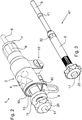
- Ein Ausführungsbeispiel der Erfindung wird nachstehend mit Bezug auf die Zeichnungen erläutert. In den Zeichnungen zeigen:
- Fig. 1
- eine Ansicht eines Schnitts eines Nietwerkzeugs;
- Fig. 2
- eine perspektivische Ansicht des Nietwerkzeugs von
Fig. 1 und - Fig. 3
- eine Perspektivische Ansicht des Ziehwerkzeugs des Nietwerkzeugs von
Fig. 1 bestehend aus Zugdorn und Druckstab. - In
Figur 1 ist eine eine Antriebseinheit 2 für ein inFig. 3 dargestelltes Ziehwerkzeug 47 aufweisendes Nietwerkzeug 1 in einer Schnittansicht dargestellt. Die Antriebseinheit 2 des Nietwerkzeugs 1 weist dabei einen Antriebskolben 3 auf, welcher innerhalb eines Zylinderabschnitts 5 eines Gehäuses 4 des Nietwerkzeugs 1 in Längsachsenrichtung des Antriebskolbens 3 verstellbar ist. - Die Verstellung des Antriebskolbens 3 erfolgt dabei aufgrund eines hydraulischen Drucks. Die hierfür erforderliche Hydraulikflüssigkeit wird über einen Anschlussstutzen 40, der über ein Gelenk 43 mit dem Gehäuse 4 verbunden ist, in den Druckraum 48 des Gehäuses 4 geleitet. Durch die Beaufschlagung des Druckraums 48 mit Hydraulikdruck erfolgt eine Verlagerung des Antriebskolbens 3 in dessen Längsachsenrichtung entgegen einer durch eine Schraubendruckfeder 15, aufgebrachten Vorspannung, wobei die Schraubendruckfeder 15 hierzu einenends in einer Ausnehmung 36 an dem Antriebskolben 3 und anderenends in einer Vertiefung 35 an einer in den Zylinderabschnitt 5 des Gehäuses 4 eingesetzten Rasthülse 10 abgestützt ist.
- Zur Verbindung des Nietwerkzeugs 1 mit einer zu setzenden, hier nicht dargestellten Blindnietmutter dient das in das Nietwerkzeug 1 eingesetzte Ziehwerkzeug 47, das im Wesentlichen aus einem Ziehdorn 8 und einem lösbar mit dem Ziehdorn 8 verbundenen Druckstab 9 besteht. Das Ziehwerkzeug 47 erstreckt sich in seiner am Nietwerkzeug 1 montierten Lage dabei in axialer Richtung durch das Gehäuse 4 so wie den längskanalisierten Antriebskolben 3.
- In der in
Figur 1 dargestellten Nietaufnahmeposition ragt der Ziehdorn 8 mit seinem freien Ende zur Anordnung der Blindnietmutter aus dem der Rasthülse 10 gegenüberliegenden Ende des Gehäuses 4 heraus. Der Ziehdorn 8 liegt in der inFigur 1 dargestellten Nietaufnahmeposition, in der der Antriebskolben 3 in seiner Ausgangsposition befindlich ist, mit einem Absatz 39 an einer Druckfläche 38 des Antriebskolbens 3 an. Eine Verlagerung des Antriebskolbens 3 in Folge einer Erhöhung des Hydraulikdrucks bewirkt somit eine Verlagerung des Zugdorns 8 in Richtung auf die Rasthülse 10 entsprechend der Längsverstellung des Antriebskolbens 3. - Zur Begrenzung der Verstellbewegung des Antriebskolbens 3 und des Ziehdorns 8 und damit zur Festlegung der Setzposition dient eine in die Rasthülse 10 eingeschraubte Stellbuchse 11, die als Hubbegrenzungselement dient. Die Stellbuchse 11 ist über ein Außengewinde 45 ein das Innengewinde 46 der Rasthülse 10 einschraubbar und so in ihrer Längsachsenrichtung gegenüber dem Gehäuse 4 positionierbar. In Abhängigkeit von der Position der Stellbuchse 11 dient somit eine Anschlagfläche 33 an der Stellbuchse als Wegbegrenzer für eine Stirnseite 34 des Antriebskolbens 3. In der hier nicht dargestellten Setzposition liegen die Anschlagfläche 33 und die Stirnseite 34 aneinander an. Die eingestellte Position der Stellbuchse 11 wird dabei über eine geeignete, selbsthemmende Gewindeverbindung 45, 46 gesichert.
- An Rastkörperträgern 14 in Öffnungen 16 der Rasthülse 10 angeordnete Rastkörper 12 dienen zur haptischen Rückmeldung der eingestellten Position der Stellbuchse 11. Nach jeweils einer halben Umdrehung der Stellbuchse 11 gelangen die Rastkörper 12 mit in Längsachsenrichtung verlaufenden Rastnuten 13 an der Umfangsfläche der Stellbuchse 11 in Eingriff. Dabei entspricht eine halbe Umdrehung einer Längenverlagerung der Stellbuchse 11 um ¼ mm.
- Der Druckstab 9 und der Ziehdorn 8 des Ziehwerkzeugs 47 sind über ein Kopplungselement 29, das mit einem Außengewinde 26 in eine mit einem Innengewinde 25 versehene Öffnung des Druckstabs 9 eingeschraubt ist lösbar miteinander verbunden, wobei zur lösbaren Verbindung das Kopplungselement an seinem dem Druckstab 9 gegenüberliegenden Ende eine Nut 37 mit einem darin angeordneten Nusshaltering 18 aufweist. In der montierten Lage greift dieser Nusshaltering 18 in eine Nut 19 an dem Zugdorn 8 ein und arretiert somit den Ziehdorn 8 lösbar an dem Druckstab 9.
- Neben der lösbaren Anordnung des Ziehdorns 8 an dem Druckstab 9 dient das Kopplungselement 29 ferner dazu, das Ziehwerkzeug 47 an dem Antriebskolben 3 festzulegen. Hierzu weist das Kopplungselement 29 eine sich senkrecht zur Längsachsenrichtung erstreckende Bohrung 30 auf, innerhalb derer Raststifte 31 angeordnet sind. In der in
Figur 1 dargestellten Sperrstellung der Raststifte 31 greifen diese in Ausnehmung 32 an dem Antriebskolben 3 ein und arretieren somit das Ziehwerkwerkzeug 47 an dem Antriebskolben 3. - Ein in
Figur 1 in der Verriegelungsstellung dargestellter Entriegelungsstab 21 verhindert dabei, dass die Raststifte 31 aus den Ausnehmungen 32 an dem Antriebskolben 3 herausgelangen. Zur Demontage des Ziehwerkzeugs 47 ist der Entriegelungsstab 21 über einen Druckknopf 17 entgegen einer durch eine Schraubendruckfeder 22 erzeugten Vorspannung in Richtung auf den Ziehdorn 8 verlagerbar, wobei in der hier nicht dargestellten Entriegelungsstellung eine Verjüngung 28 mit den Raststiften 31 in Eingriff gelangt und diesen die Möglichkeit bietet, aus den Ausnehmungen 32 an dem Antriebskolben 3 herauszugelangen. In der Entriegelungsstellung kann dann das Ziehwerkzeug 47 aus dem Nietwerkzeug 1 entnommen werden. - Der Druckknopf 17 zur Betätigung des Entriegelungsstabs 21 ist dabei an einem Handgriff 20 verschiebbar gelagert, welcher auf ein Außengewinde 23 des Druckstabs 9 aufgeschraubt ist, wobei hierzu der Handgriff 20 ein entsprechend ausgebildetes Innengewinde 27 aufweist. Zur Beschränkung der Bewegung des Entriegelungsstabs 21 in Richtung auf den Druckknopf 17 dient ein Sprengring 24 welcher in der Verriegelungsstellung an einer senkrecht zur Längsachsenrichtung verlaufenden Innenfläche des Druckstabs 9 anliegt.
- Der Zugdorn 8 weist zur Linearführung einen Führungsring 41 auf, welcher einstückig mit dem Zugdorn 8 ausgebildet ist und an einer Innenfläche des Antriebskolbens 3 anliegt. Der Antriebskolben 3 ist dabei in einer Führungsbuchse 6 verschiebbar gelagert, wobei die Führungsbuchse 6 ferner mit Magnethaltern 42 zur lösbaren Anordnung eines Setzkopfs 7 ausgebildet ist.
Bezugszeichenliste 1 Nietwerkzeug 27 Innengewinde 2 Antriebseinheit 28 Verjüngung 3 Antriebskolben 29 Kopplungselement 4 Gehäuse 30 Bohrung 5 Zylinderabschnitt 31 Raststifte 6 Führungsbuchse 32 Ausnehmungen 7 Setzkopf 33 Anschlagfläche 8 Ziehdorn 34 Stirnseite 9 Druckstab 35 Vertiefung 10 Rasthülse 36 Ausnehmung 11 Hubbegrenzungselement(Stellbuchse) 37 Nut 12 Rastkörper 38 Druckfläche 13 Rastnut 39 Absatz 14 Rastkörperträger 40 Anschlussstutzen 15 Schraubendruckfeder 41 Führungsring 16 Öffnung 42 Magnethalter 17 Druckknopf 43 Gelenk 18 Nusshaltering 44 Stelleinheit 19 Nut (Ziehdorn) 45 Außengewinde 20 Handgriff 46 Innengewinde 21 Entriegelungsstab 47 Ziehwerkzeug 22 Schraubendruckfeder 48 Druckraum 23 Außengewinde 24 Sprengring 25 Innengewinde 26 Außengewinde
Claims (10)
- Nietwerkzeug zum Setzen von Blindnietmuttern und/oder Blindnietschrauben, mit- einem hydraulisch aus einer Ausgangsposition in Richtung auf eine Endposition verstellbaren Antriebskolben (3) und- einem mit dem Antriebskolben (3) lösbar in Wirkverbindung bringbaren und durch den Antriebskolben (3) zwischen einer Nietaufnahmeposition und einer Setzposition verstellbaren Ziehdorn (8) und- einer Stelleinheit mit einem in Längsachsenrichtung des Antriebskolbens (3) verstellbaren und mit dem Antriebskolben (3) in Eingriff bringbaren Hubbegrenzungselement (11) zur Festlegung der Setzposition des Ziehdorns (8),
dadurch gekennzeichnet, dass- der Ziehdorn (8) mit einem über ein Kopplungselement (29) lösbar mit diesem verbundenen Druckstab (9) ein zweiteiliges Ziehwerkzeug ausbildet und- das Kopplungselement (29) zur lösbaren Verriegelung an dem Antriebskolben (3) ausgebildet ist und mindestens ein zwischen einer Verriegelungsstellung und einer Entriegelungsstellung verstellbares Sperrelement (31) aufweist und das Sperrelement, insbesondere ein Raststift (31), mittels eines sich durch den Druckstab (9) erstreckenden, zwischen einer Sperrstellung und einer Freigabestellung verlagerbaren Entriegelungsstabs (21) zwischen der Verriegelungsstellung und der Entriegelungsstellung verstellbar ist. - Nietwerkzeug nach Anspruch 1, dadurch gekennzeichnet, dass das Hubbegrenzungselement als Stellbuchse (11) ausgebildet ist, die über ein Außengewinde (45) mit einer an einem Gehäuse (4) des Nietwerkzeugs (1) festgelegten Rasthülse (10) in Längsachsenrichtung des Antriebskolbens (3) verstellbar verbunden ist.
- Nietwerkzeug nach Anspruch 2, dadurch gekennzeichnet, dass eine dem Antriebskolben (3) zugewandte Anschlagfläche (33) der Stellbuchse (11) zur Anlage an einer der Anschlagfläche (33) zugewandten Stirnseite (34) des Antriebskolbens (3) ausgebildet ist, insbesondere eine Beschichtung aufweist.
- Nietwerkzeug nach Anspruch 2 oder 3, dadurch gekennzeichnet, dass die Stellbuchse (11) Rastmarken (13) aufweist, die mit Rastkörpern (12) an der Rasthülse (10) in Eingriff bringbar sind.
- Nietwerkzeug nach Anspruch 4, dadurch gekennzeichnet, dass die Rastmarken durch mindestens eine in Längsachsenrichtung der Stellbuchse (11) verlaufende Rastnut (13) gebildet sind.
- Nietwerkzeug nach einem der vorhergehenden Ansprüche, dadurch gekennzeichnet, dass der Ziehdorn (8) lösbar mit dem Druckstab (9) verbunden ist, der sich in Längsachsenrichtung des Antriebskolbens (3) durch die Stellbuchse (11) erstreckt.
- Nietwerkzeug nach einem der vorhergehenden Ansprüche, dadurch gekennzeichnet, dass der Druckstab (9) an seinem dem Ziehdorn (8) zugewandten Ende ein Kopplungselement (29) aufweist, das zur lösbaren Verbindung mit dem Ziehdorn (8) ausgebildet ist, insbesondere einen in einer Nut (37) angeordneten Nusshaltering (18) aufweist, der in eine Nut an dem Ziehdorn (8) eingreift
- Nietwerkzeug nach einem der vorhergehenden Ansprüche, dadurch gekennzeichnet, dass der Entriegelungsstab (21) in Richtung auf die Sperrstellung und/oder der Antriebskolben (3) in Richtung auf die Ausgangsposition vorgespannt ist.
- Nietwerkzeug nach einem der vorhergehenden Ansprüche, dadurch gekennzeichnet, dass der Entriegelungsstab (21) an seinem dem Kopplungselement (29) gegenüberliegenden Ende einen verstellbar an einem Handgriff (20) gelagerten Druckknopf (17) aufweist.
- Nietwerkzeug nach einem der vorhergehenden Ansprüche, dadurch gekennzeichnet, dass ein koaxial zum Ziehdorn (8) angeordneter Setzkopf (7) lösbar, insbesondere magnetisch an dem Gehäuse (4) befestigbar ist.
Applications Claiming Priority (1)
| Application Number | Priority Date | Filing Date | Title |
|---|---|---|---|
| DE102015116559.7A DE102015116559B4 (de) | 2015-09-30 | 2015-09-30 | Werkzeugwechsel bei Blindnietmuttern |
Publications (3)
| Publication Number | Publication Date |
|---|---|
| EP3159112A2 EP3159112A2 (de) | 2017-04-26 |
| EP3159112A3 EP3159112A3 (de) | 2017-08-30 |
| EP3159112B1 true EP3159112B1 (de) | 2019-06-26 |
Family
ID=57046988
Family Applications (1)
| Application Number | Title | Priority Date | Filing Date |
|---|---|---|---|
| EP16190451.1A Active EP3159112B1 (de) | 2015-09-30 | 2016-09-23 | Nietwerkzeug mit hubbegrenzung |
Country Status (3)
| Country | Link |
|---|---|
| US (1) | US9724751B2 (de) |
| EP (1) | EP3159112B1 (de) |
| DE (1) | DE102015116559B4 (de) |
Families Citing this family (6)
| Publication number | Priority date | Publication date | Assignee | Title |
|---|---|---|---|---|
| CN105792961B (zh) * | 2013-12-06 | 2018-11-13 | 三菱重工业株式会社 | 胀口工具 |
| US11110580B2 (en) | 2018-03-22 | 2021-09-07 | James Kevin Panks | Pneumatic percussive tool with attachments and method of use thereof |
| US11673243B2 (en) | 2018-09-05 | 2023-06-13 | Milwaukee Electric Tool Corporation | Blind rivet nut-setting tool |
| US12453999B2 (en) | 2021-07-28 | 2025-10-28 | Milwaukee Electric Tool Corporation | Blind rivet nut-setting tool |
| CN115383034B (zh) * | 2022-10-10 | 2026-03-17 | 矩省(上海)科技股份有限公司 | 一种电动拉铆枪 |
| CN118081689A (zh) * | 2024-01-25 | 2024-05-28 | 中国船舶集团有限公司第七〇七研究所 | 适用于球铰链、锁套装配及铆装的专用装置及其使用方法 |
Family Cites Families (15)
| Publication number | Priority date | Publication date | Assignee | Title |
|---|---|---|---|---|
| US2723777A (en) * | 1952-07-15 | 1955-11-15 | Chicago Pneumatic Tool Co | Power driven tool for upsetting tubular rivets or clinch nuts |
| US3871203A (en) * | 1974-03-25 | 1975-03-18 | U S Ind Tool & Supply Co | Tubular fastener setting power tool |
| US4425782A (en) * | 1981-12-03 | 1984-01-17 | Marson Corporation | Hand-held setting tool and method for setting deformable head fasteners |
| EP0121665A3 (de) * | 1983-02-10 | 1986-05-14 | SMW Schneider & Weisshaupt GmbH | Vorrichtung zum Einspannen von Wechselkassetten |
| DE8422476U1 (de) * | 1984-07-26 | 1984-10-31 | Kraftwerk Union AG, 4330 Mülheim | Werkzeug zum herausziehen eines rohrstueckes aus einem rohrboden |
| DE29914202U1 (de) * | 1999-08-13 | 2000-12-21 | MS Verwaltungs- und Patentgesellschaft mbH., 49084 Osnabrück | Nietsetzwerkzeug mit Hubeinstellung |
| DE10108201A1 (de) * | 2001-02-21 | 2002-08-22 | Bosch Gmbh Robert | Spannbaugruppe |
| US7155953B1 (en) * | 2004-05-19 | 2007-01-02 | Nikkel Robert E | Anvil driving assembly |
| US7032281B1 (en) * | 2005-02-17 | 2006-04-25 | Yu-Ching Lin | Rivet-stroke adjusting device for a rivet-nut gun |
| DE102005022748A1 (de) * | 2005-05-18 | 2006-11-23 | Martin Lindner | Blindnietmuttern-Setzkopf für Hydraulikzylinder |
| DE102006026610A1 (de) * | 2005-07-21 | 2007-02-08 | Preh Gmbh | Bedienelement mit einstellbarer Rast |
| GB2442447B (en) * | 2006-10-03 | 2009-06-03 | Textron Fastening Syst Ltd | Improved riveting apparatus |
| DE102007030644A1 (de) * | 2007-07-02 | 2009-01-08 | Gustav Klauke Gmbh | Hydraulisch betätigbares Handwerkzeug |
| DE102010022022B4 (de) | 2010-05-29 | 2012-01-19 | Gesipa Blindniettechnik Gmbh | Blindnietmuttern-Setzgerät |
| DE102010024610B4 (de) | 2010-06-22 | 2012-02-16 | Gesipa Blindniettechnik Gmbh | Setzgerät mit einer variablen Setzhubeinstellung |
-
2015
- 2015-09-30 DE DE102015116559.7A patent/DE102015116559B4/de active Active
-
2016
- 2016-09-23 EP EP16190451.1A patent/EP3159112B1/de active Active
- 2016-09-30 US US15/282,962 patent/US9724751B2/en active Active
Non-Patent Citations (1)
| Title |
|---|
| None * |
Also Published As
| Publication number | Publication date |
|---|---|
| DE102015116559B4 (de) | 2018-11-08 |
| EP3159112A3 (de) | 2017-08-30 |
| DE102015116559A1 (de) | 2017-03-30 |
| US20170087621A1 (en) | 2017-03-30 |
| EP3159112A2 (de) | 2017-04-26 |
| US9724751B2 (en) | 2017-08-08 |
Similar Documents
| Publication | Publication Date | Title |
|---|---|---|
| DE102015116559B4 (de) | Werkzeugwechsel bei Blindnietmuttern | |
| EP3167973B1 (de) | Nietwerkzeug | |
| EP3025807B1 (de) | Nietwerkzeug | |
| DE102010009172A1 (de) | Dehnspanndorn und Dehnspannfutter | |
| EP2414114B1 (de) | Stanzwerkzeug | |
| DE112018004511T5 (de) | Druckfluidabgabesteuervorrichtung | |
| EP2146812B1 (de) | Spanabhebendes werkzeug | |
| EP2399712B1 (de) | Setzgerät mit einer variablen Setzhubeinstellung | |
| EP3025824B1 (de) | Mobiles hydraulikwerkzeug | |
| EP3470147A1 (de) | Hydraulisches stanzgerät | |
| DE202018100313U1 (de) | Spannfutter für den schnellen Werkzeugwechsel | |
| EP1888280B1 (de) | Verbindung zwischen zwei werkzeugteilen | |
| EP2777848B1 (de) | Spann- oder Greifeinrichtung | |
| DE4204644C2 (de) | Vorrichtung zur Einstellung eines Werkzeuganschlags in einer Werkzeugspindel | |
| DE102007007636B3 (de) | Abzieher | |
| EP2777850B1 (de) | Spann- oder Greifeinrichtung | |
| DE202017105292U1 (de) | Nutenstein | |
| EP1431003A1 (de) | Kraftspannfutter und Ausklinkschlüssel dafür | |
| EP4484063B1 (de) | Handhaltbare zug- und druckvorrichtung sowie hydraulikaktuator | |
| EP1317997B1 (de) | Schaft für einen Drehmomentschlüssel | |
| EP2777849A1 (de) | Spann- oder Greifeinrichtung | |
| DE102019100890A1 (de) | Bohrkopf und Verfahren zum Auskesseln von Sackbohrungen | |
| DE102006001312A1 (de) | Steckschlüsselverlängerung | |
| DE19934663A1 (de) | Vorrichtung zum Lochen von Werkstücken beim Innenhochdruckumformen | |
| DE20023264U1 (de) | Vorsatzgerät zum Stanzen von Polygonlöchern |
Legal Events
| Date | Code | Title | Description |
|---|---|---|---|
| PUAI | Public reference made under article 153(3) epc to a published international application that has entered the european phase |
Free format text: ORIGINAL CODE: 0009012 |
|
| STAA | Information on the status of an ep patent application or granted ep patent |
Free format text: STATUS: THE APPLICATION HAS BEEN PUBLISHED |
|
| AK | Designated contracting states |
Kind code of ref document: A2 Designated state(s): AL AT BE BG CH CY CZ DE DK EE ES FI FR GB GR HR HU IE IS IT LI LT LU LV MC MK MT NL NO PL PT RO RS SE SI SK SM TR |
|
| AX | Request for extension of the european patent |
Extension state: BA ME |
|
| PUAL | Search report despatched |
Free format text: ORIGINAL CODE: 0009013 |
|
| AK | Designated contracting states |
Kind code of ref document: A3 Designated state(s): AL AT BE BG CH CY CZ DE DK EE ES FI FR GB GR HR HU IE IS IT LI LT LU LV MC MK MT NL NO PL PT RO RS SE SI SK SM TR |
|
| AX | Request for extension of the european patent |
Extension state: BA ME |
|
| RIC1 | Information provided on ipc code assigned before grant |
Ipc: B25B 27/00 20060101AFI20170725BHEP |
|
| STAA | Information on the status of an ep patent application or granted ep patent |
Free format text: STATUS: REQUEST FOR EXAMINATION WAS MADE |
|
| 17P | Request for examination filed |
Effective date: 20180215 |
|
| RBV | Designated contracting states (corrected) |
Designated state(s): AL AT BE BG CH CY CZ DE DK EE ES FI FR GB GR HR HU IE IS IT LI LT LU LV MC MK MT NL NO PL PT RO RS SE SI SK SM TR |
|
| GRAP | Despatch of communication of intention to grant a patent |
Free format text: ORIGINAL CODE: EPIDOSNIGR1 |
|
| STAA | Information on the status of an ep patent application or granted ep patent |
Free format text: STATUS: GRANT OF PATENT IS INTENDED |
|
| RIC1 | Information provided on ipc code assigned before grant |
Ipc: B25D 9/12 20060101ALI20190121BHEP Ipc: B21J 15/04 20060101ALI20190121BHEP Ipc: B21J 15/10 20060101ALI20190121BHEP Ipc: B21J 15/20 20060101ALI20190121BHEP Ipc: B25B 27/00 20060101AFI20190121BHEP Ipc: B21J 15/32 20060101ALI20190121BHEP |
|
| INTG | Intention to grant announced |
Effective date: 20190205 |
|
| GRAS | Grant fee paid |
Free format text: ORIGINAL CODE: EPIDOSNIGR3 |
|
| GRAA | (expected) grant |
Free format text: ORIGINAL CODE: 0009210 |
|
| STAA | Information on the status of an ep patent application or granted ep patent |
Free format text: STATUS: THE PATENT HAS BEEN GRANTED |
|
| AK | Designated contracting states |
Kind code of ref document: B1 Designated state(s): AL AT BE BG CH CY CZ DE DK EE ES FI FR GB GR HR HU IE IS IT LI LT LU LV MC MK MT NL NO PL PT RO RS SE SI SK SM TR |
|
| REG | Reference to a national code |
Ref country code: GB Ref legal event code: FG4D Free format text: NOT ENGLISH |
|
| REG | Reference to a national code |
Ref country code: CH Ref legal event code: EP |
|
| REG | Reference to a national code |
Ref country code: AT Ref legal event code: REF Ref document number: 1147759 Country of ref document: AT Kind code of ref document: T Effective date: 20190715 |
|
| REG | Reference to a national code |
Ref country code: DE Ref legal event code: R096 Ref document number: 502016005219 Country of ref document: DE |
|
| REG | Reference to a national code |
Ref country code: IE Ref legal event code: FG4D Free format text: LANGUAGE OF EP DOCUMENT: GERMAN |
|
| REG | Reference to a national code |
Ref country code: NL Ref legal event code: MP Effective date: 20190626 |
|
| PG25 | Lapsed in a contracting state [announced via postgrant information from national office to epo] |
Ref country code: HR Free format text: LAPSE BECAUSE OF FAILURE TO SUBMIT A TRANSLATION OF THE DESCRIPTION OR TO PAY THE FEE WITHIN THE PRESCRIBED TIME-LIMIT Effective date: 20190626 Ref country code: LT Free format text: LAPSE BECAUSE OF FAILURE TO SUBMIT A TRANSLATION OF THE DESCRIPTION OR TO PAY THE FEE WITHIN THE PRESCRIBED TIME-LIMIT Effective date: 20190626 Ref country code: FI Free format text: LAPSE BECAUSE OF FAILURE TO SUBMIT A TRANSLATION OF THE DESCRIPTION OR TO PAY THE FEE WITHIN THE PRESCRIBED TIME-LIMIT Effective date: 20190626 Ref country code: AL Free format text: LAPSE BECAUSE OF FAILURE TO SUBMIT A TRANSLATION OF THE DESCRIPTION OR TO PAY THE FEE WITHIN THE PRESCRIBED TIME-LIMIT Effective date: 20190626 Ref country code: SE Free format text: LAPSE BECAUSE OF FAILURE TO SUBMIT A TRANSLATION OF THE DESCRIPTION OR TO PAY THE FEE WITHIN THE PRESCRIBED TIME-LIMIT Effective date: 20190626 Ref country code: NO Free format text: LAPSE BECAUSE OF FAILURE TO SUBMIT A TRANSLATION OF THE DESCRIPTION OR TO PAY THE FEE WITHIN THE PRESCRIBED TIME-LIMIT Effective date: 20190926 |
|
| REG | Reference to a national code |
Ref country code: LT Ref legal event code: MG4D |
|
| PG25 | Lapsed in a contracting state [announced via postgrant information from national office to epo] |
Ref country code: LV Free format text: LAPSE BECAUSE OF FAILURE TO SUBMIT A TRANSLATION OF THE DESCRIPTION OR TO PAY THE FEE WITHIN THE PRESCRIBED TIME-LIMIT Effective date: 20190626 Ref country code: GR Free format text: LAPSE BECAUSE OF FAILURE TO SUBMIT A TRANSLATION OF THE DESCRIPTION OR TO PAY THE FEE WITHIN THE PRESCRIBED TIME-LIMIT Effective date: 20190927 Ref country code: RS Free format text: LAPSE BECAUSE OF FAILURE TO SUBMIT A TRANSLATION OF THE DESCRIPTION OR TO PAY THE FEE WITHIN THE PRESCRIBED TIME-LIMIT Effective date: 20190626 Ref country code: BG Free format text: LAPSE BECAUSE OF FAILURE TO SUBMIT A TRANSLATION OF THE DESCRIPTION OR TO PAY THE FEE WITHIN THE PRESCRIBED TIME-LIMIT Effective date: 20190926 |
|
| PG25 | Lapsed in a contracting state [announced via postgrant information from national office to epo] |
Ref country code: PT Free format text: LAPSE BECAUSE OF FAILURE TO SUBMIT A TRANSLATION OF THE DESCRIPTION OR TO PAY THE FEE WITHIN THE PRESCRIBED TIME-LIMIT Effective date: 20191028 Ref country code: RO Free format text: LAPSE BECAUSE OF FAILURE TO SUBMIT A TRANSLATION OF THE DESCRIPTION OR TO PAY THE FEE WITHIN THE PRESCRIBED TIME-LIMIT Effective date: 20190626 Ref country code: CZ Free format text: LAPSE BECAUSE OF FAILURE TO SUBMIT A TRANSLATION OF THE DESCRIPTION OR TO PAY THE FEE WITHIN THE PRESCRIBED TIME-LIMIT Effective date: 20190626 Ref country code: NL Free format text: LAPSE BECAUSE OF FAILURE TO SUBMIT A TRANSLATION OF THE DESCRIPTION OR TO PAY THE FEE WITHIN THE PRESCRIBED TIME-LIMIT Effective date: 20190626 Ref country code: EE Free format text: LAPSE BECAUSE OF FAILURE TO SUBMIT A TRANSLATION OF THE DESCRIPTION OR TO PAY THE FEE WITHIN THE PRESCRIBED TIME-LIMIT Effective date: 20190626 Ref country code: SK Free format text: LAPSE BECAUSE OF FAILURE TO SUBMIT A TRANSLATION OF THE DESCRIPTION OR TO PAY THE FEE WITHIN THE PRESCRIBED TIME-LIMIT Effective date: 20190626 |
|
| PG25 | Lapsed in a contracting state [announced via postgrant information from national office to epo] |
Ref country code: ES Free format text: LAPSE BECAUSE OF FAILURE TO SUBMIT A TRANSLATION OF THE DESCRIPTION OR TO PAY THE FEE WITHIN THE PRESCRIBED TIME-LIMIT Effective date: 20190626 Ref country code: SM Free format text: LAPSE BECAUSE OF FAILURE TO SUBMIT A TRANSLATION OF THE DESCRIPTION OR TO PAY THE FEE WITHIN THE PRESCRIBED TIME-LIMIT Effective date: 20190626 Ref country code: IS Free format text: LAPSE BECAUSE OF FAILURE TO SUBMIT A TRANSLATION OF THE DESCRIPTION OR TO PAY THE FEE WITHIN THE PRESCRIBED TIME-LIMIT Effective date: 20191026 |
|
| PG25 | Lapsed in a contracting state [announced via postgrant information from national office to epo] |
Ref country code: TR Free format text: LAPSE BECAUSE OF FAILURE TO SUBMIT A TRANSLATION OF THE DESCRIPTION OR TO PAY THE FEE WITHIN THE PRESCRIBED TIME-LIMIT Effective date: 20190626 |
|
| PG25 | Lapsed in a contracting state [announced via postgrant information from national office to epo] |
Ref country code: DK Free format text: LAPSE BECAUSE OF FAILURE TO SUBMIT A TRANSLATION OF THE DESCRIPTION OR TO PAY THE FEE WITHIN THE PRESCRIBED TIME-LIMIT Effective date: 20190626 Ref country code: PL Free format text: LAPSE BECAUSE OF FAILURE TO SUBMIT A TRANSLATION OF THE DESCRIPTION OR TO PAY THE FEE WITHIN THE PRESCRIBED TIME-LIMIT Effective date: 20190626 |
|
| PG25 | Lapsed in a contracting state [announced via postgrant information from national office to epo] |
Ref country code: MC Free format text: LAPSE BECAUSE OF FAILURE TO SUBMIT A TRANSLATION OF THE DESCRIPTION OR TO PAY THE FEE WITHIN THE PRESCRIBED TIME-LIMIT Effective date: 20190626 Ref country code: IS Free format text: LAPSE BECAUSE OF FAILURE TO SUBMIT A TRANSLATION OF THE DESCRIPTION OR TO PAY THE FEE WITHIN THE PRESCRIBED TIME-LIMIT Effective date: 20200224 |
|
| REG | Reference to a national code |
Ref country code: CH Ref legal event code: PL |
|
| REG | Reference to a national code |
Ref country code: DE Ref legal event code: R097 Ref document number: 502016005219 Country of ref document: DE |
|
| PLBE | No opposition filed within time limit |
Free format text: ORIGINAL CODE: 0009261 |
|
| STAA | Information on the status of an ep patent application or granted ep patent |
Free format text: STATUS: NO OPPOSITION FILED WITHIN TIME LIMIT |
|
| PG2D | Information on lapse in contracting state deleted |
Ref country code: IS |
|
| PG25 | Lapsed in a contracting state [announced via postgrant information from national office to epo] |
Ref country code: LU Free format text: LAPSE BECAUSE OF NON-PAYMENT OF DUE FEES Effective date: 20190923 Ref country code: IE Free format text: LAPSE BECAUSE OF NON-PAYMENT OF DUE FEES Effective date: 20190923 Ref country code: CH Free format text: LAPSE BECAUSE OF NON-PAYMENT OF DUE FEES Effective date: 20190930 Ref country code: LI Free format text: LAPSE BECAUSE OF NON-PAYMENT OF DUE FEES Effective date: 20190930 |
|
| 26N | No opposition filed |
Effective date: 20200603 |
|
| REG | Reference to a national code |
Ref country code: BE Ref legal event code: MM Effective date: 20190930 |
|
| PG25 | Lapsed in a contracting state [announced via postgrant information from national office to epo] |
Ref country code: SI Free format text: LAPSE BECAUSE OF FAILURE TO SUBMIT A TRANSLATION OF THE DESCRIPTION OR TO PAY THE FEE WITHIN THE PRESCRIBED TIME-LIMIT Effective date: 20190626 Ref country code: BE Free format text: LAPSE BECAUSE OF NON-PAYMENT OF DUE FEES Effective date: 20190930 |
|
| PG25 | Lapsed in a contracting state [announced via postgrant information from national office to epo] |
Ref country code: CY Free format text: LAPSE BECAUSE OF FAILURE TO SUBMIT A TRANSLATION OF THE DESCRIPTION OR TO PAY THE FEE WITHIN THE PRESCRIBED TIME-LIMIT Effective date: 20190626 |
|
| PG25 | Lapsed in a contracting state [announced via postgrant information from national office to epo] |
Ref country code: MT Free format text: LAPSE BECAUSE OF FAILURE TO SUBMIT A TRANSLATION OF THE DESCRIPTION OR TO PAY THE FEE WITHIN THE PRESCRIBED TIME-LIMIT Effective date: 20190626 Ref country code: HU Free format text: LAPSE BECAUSE OF FAILURE TO SUBMIT A TRANSLATION OF THE DESCRIPTION OR TO PAY THE FEE WITHIN THE PRESCRIBED TIME-LIMIT; INVALID AB INITIO Effective date: 20160923 |
|
| PG25 | Lapsed in a contracting state [announced via postgrant information from national office to epo] |
Ref country code: MK Free format text: LAPSE BECAUSE OF FAILURE TO SUBMIT A TRANSLATION OF THE DESCRIPTION OR TO PAY THE FEE WITHIN THE PRESCRIBED TIME-LIMIT Effective date: 20190626 |
|
| REG | Reference to a national code |
Ref country code: AT Ref legal event code: MM01 Ref document number: 1147759 Country of ref document: AT Kind code of ref document: T Effective date: 20210923 |
|
| PG25 | Lapsed in a contracting state [announced via postgrant information from national office to epo] |
Ref country code: AT Free format text: LAPSE BECAUSE OF NON-PAYMENT OF DUE FEES Effective date: 20210923 |
|
| PGFP | Annual fee paid to national office [announced via postgrant information from national office to epo] |
Ref country code: DE Payment date: 20250925 Year of fee payment: 10 |
|
| PGFP | Annual fee paid to national office [announced via postgrant information from national office to epo] |
Ref country code: GB Payment date: 20250923 Year of fee payment: 10 |
|
| PGFP | Annual fee paid to national office [announced via postgrant information from national office to epo] |
Ref country code: FR Payment date: 20250925 Year of fee payment: 10 |
|
| PGFP | Annual fee paid to national office [announced via postgrant information from national office to epo] |
Ref country code: IT Payment date: 20250930 Year of fee payment: 10 |