EP3158841A1 - Bodenwalze - Google Patents
Bodenwalze Download PDFInfo
- Publication number
- EP3158841A1 EP3158841A1 EP16401068.8A EP16401068A EP3158841A1 EP 3158841 A1 EP3158841 A1 EP 3158841A1 EP 16401068 A EP16401068 A EP 16401068A EP 3158841 A1 EP3158841 A1 EP 3158841A1
- Authority
- EP
- European Patent Office
- Prior art keywords
- support
- rings
- soil
- roller according
- groove
- Prior art date
- Legal status (The legal status is an assumption and is not a legal conclusion. Google has not performed a legal analysis and makes no representation as to the accuracy of the status listed.)
- Granted
Links
Images


Classifications
-
- A—HUMAN NECESSITIES
- A01—AGRICULTURE; FORESTRY; ANIMAL HUSBANDRY; HUNTING; TRAPPING; FISHING
- A01B—SOIL WORKING IN AGRICULTURE OR FORESTRY; PARTS, DETAILS, OR ACCESSORIES OF AGRICULTURAL MACHINES OR IMPLEMENTS, IN GENERAL
- A01B29/00—Rollers
- A01B29/04—Rollers with non-smooth surface formed of rotatably-mounted rings or discs or with projections or ribs on the roller body; Land packers
-
- A—HUMAN NECESSITIES
- A01—AGRICULTURE; FORESTRY; ANIMAL HUSBANDRY; HUNTING; TRAPPING; FISHING
- A01B—SOIL WORKING IN AGRICULTURE OR FORESTRY; PARTS, DETAILS, OR ACCESSORIES OF AGRICULTURAL MACHINES OR IMPLEMENTS, IN GENERAL
- A01B29/00—Rollers
- A01B29/04—Rollers with non-smooth surface formed of rotatably-mounted rings or discs or with projections or ribs on the roller body; Land packers
- A01B29/041—Rollers with non-smooth surface formed of rotatably-mounted rings or discs or with projections or ribs on the roller body; Land packers of "Cambridge"-type, i.e. the soil-pressing rings being stacked on a shaft
- A01B29/043—Tyre-packers
Definitions
- the invention relates to a bottom roller according to the preamble of claim 1.
- Ground rollers in particular so-called wedge ring rollers, serve primarily to purposefully consolidate the loosened soil again before or after the introduction of the seed.
- corresponding bottom rollers as in the EP 0 861 577 B1 is shown equipped with a plurality of so-called soil compaction rings, which are spaced from each other on a support body.
- the support body may be, for example, a hollow body such as a pipe, but also bodies of solid material or filled bodies such as an axle or the like.
- the soil compaction rings can be made of a variety of materials. Preferably, it is elastic materials, in particular rubber. By said spacing of the soil compaction rings, a targeted, strip-like reconsolidation of the soil is made possible, in particular in the region of the mutually parallel seed furrows. When seeds are introduced into the reconsolidated area, it finds optimized conditions for growth.
- the soil compaction rings can be provided with nubs on the circumference, for example, or they can be smooth, as can any longitudinal or transverse profiles.
- the individual soil compaction rings of the bottom roller are plugged with their central openings on the support body.
- a so-called spacer ring is provided as a spacer.
- These are in particular cylindrical plastic rings.
- all spacer rings have the same width.
- the soil compaction rings laterally encircling retaining grooves. In these retaining grooves, the spacer rings are inserted with their free side edges.
- the retaining grooves of the soil compaction rings arranged on both sides can be carried out in particular in a dovetail shape on the inner diameter of the soil compaction rings.
- a disadvantage of the known bottom rollers as wedge ring rollers is that the two arranged at the end regions of the bottom roller outer soil compaction rings are subject to higher wear and show stability problems with the known ferrules clamping.
- a solution proposed in practice for enlarging the clamping blank by means of a supporting edge thereby causes dirt to settle in the area of the clamping blank and soil compacting rings. In addition, it can lead to increased wear of soil compaction rings. As a result, the operation and life of the bottom roller is significantly limited, especially at the edge.
- the object of the present invention is therefore to improve the design of the outer soil compaction rings and / or the Klemmronden to the effect that an improved support and life is achieved.
- each of the two outer soil compaction rings on the support body on at least one support groove, which is provided for engagement of a supporting body connected to the support portion.
- the support section ensures that the outer soil compaction ring is supported in a special way in the lateral direction.
- lateral forces are better absorbed than is the case in the prior art.
- the training provides more interlocking Support groove and support portion for the penetration of dirt in the area between the support portion and soil compaction ring is largely prevented.
- the at least one support groove is arranged in the side surface or side flank of the at least one soil compacting ring. More preferably, the at least one retaining groove is arranged in the side surface or side flank of the at least one soil compacting ring, in particular the outer soil compacting rings. This ensures that the support section or the spacer rings can laterally engage in the corresponding grooves of the soil compaction rings. Thus, a secure and stable attachment is achieved. It is achieved overall that on the one hand the soil compaction rings are securely fixed by means of the retaining groove on the support body and on the other hand there is a stable support of the outer soil compaction rings by means of the support groove.
- the outer soil compaction rings on only one side support grooves are arranged only on a side surface or side edge, preferably the outwardly facing, ie in particular on the outside of the soil compacting ring after its placement on the support body.
- the support grooves are typically required only at the outer end portions of the bottom roller, since it requires a special support there. Thus, the support grooves are formed only on these outer sides.
- the support groove and / or the retaining groove is / are preferably circular, preferably circular in circumference.
- the groove is formed as a circular groove on Bodenverdichtungsring.
- this circular groove is circularly symmetrical about the center of the soil compacting ring, especially in the side flank of the soil compacting ring.
- a symmetrical design of the roller is achieved.
- the diameter of the support groove is preferably larger than the diameter of the retaining groove. Since the support groove serves to additionally support the outer soil compacting ring, a larger diameter of the support groove is provided as the retaining groove.
- the outer soil compacting ring can be better supported against lateral forces.
- the cross section of the edge-side support portion is preferably formed corresponding to the cross-section of the support groove.
- Supporting portion and support groove are preferably formed positively to one another.
- the support portion engages in particular a form-fitting manner in the support groove.
- the support groove and / or the support portion preferably have at least substantially a semicircular, trapezoidal and / or rectangular cross section.
- Such geometries have particular advantages in the production.
- a semicircular, trapezoidal or rectangular cross section of a groove can advantageously be easily formed.
- a corresponding corresponding design of the support portion is just as easy to produce.
- support portion and support groove but also have other cross-sections, such as in particular (circular) arcuate, elliptical, polygonal cross-sections or combinations thereof.
- the soil compaction rings and the spacer rings are clamped together on the support body. This is preferably done by means of two end faces or on the outside of the support body arranged Klemmronden. These are arranged on the longitudinal end regions of the bottom roll. At least one of the Klemmronden, preferably both Klemmronden are detachably connected to the support body. In particular, screws or other releasable connection means are used for this purpose. By screws can be adjusted in particular the contact pressure or clamping force of the package of soil compaction rings and spacer rings on the support body. Thus, optimal pressure force for securely fixing the components of the bottom roller can be adjusted.
- the support portion for engaging in the support groove is formed in particular on the at least one Klemmronde.
- the support portion is formed on the edge side or peripherally of the clamping blank. This means that the peripheral support portion is provided on the outer circumference of the Klemmronde.
- the support portion of the clamping ridge is preferably formed from the material of the clamping ridge.
- the support section is formed or bent from the material of the clamping blank. This means that the entire clamping blade is produced by a forming process, such as a pressing operation, including the supporting portion.
- the Klemmronde is preferably integrally formed with the support portion, thus formed from a piece of material. This ensures a simple and economical way of production.
- the support section is designed in particular as a U-shaped edge section of the clamping blank. It is in particular a peripheral edge portion of the clamping plate.
- the U-shaped configuration can be seen in particular in a sectional view of the clamping plate perpendicular to the plane of the blank.
- the support portion can engage in the corresponding support groove, the support portion is formed as a U-shaped profile at the edge of the clamping blank.
- the clamping blade engages in particular both in the retaining groove and in the supporting groove of the associated outer soil compacting ring.
- the Klemmronde both a holding portion and a support portion. This is especially described above.
- the holding portion of the clamping blade corresponds in effect to the engaging spacer rings, which are arranged between the soil compacting rings.
- the Klemmronde preferably simultaneously fulfills the function of fixing and holding the soil compacting ring on the support body on the one hand and the support on the outer edge on the other.
- the contact between Bodenverdichtungsring and Klemmronde is provided in the manner of a labyrinth seal, namely in particular the engagement of the Klemmronde in support groove and retaining groove of the soil compacting ring.
- a labyrinth seal thereby fulfills its purpose that several interlocking sections of two profiled body to be sealed against each other abut each other. By a corresponding toothing or profiling a straight passage of dirt or similar particles between soil compaction ring and clamping blade is largely prevented.
- the outer diameter of the clamping ring is greater than the outer diameter of the spacer rings.
- a sufficient support in particular of the outer soil compacting ring in the lateral direction is achieved to the outside.
- the support portion of the clamping ring is provided with a larger outer diameter than the spacer rings.
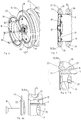
- the Fig. 1 shows a section of a bottom roller 10 in a perspective view.
- the FIGS. 2 and 3 show these as sectional views, Fig. 3a as an exploded view. Shown here is in each case only one of the two end regions of the bottom roll 10, which are typically formed identically.
- the bottom roller 10 has an elongated support tube 11. On this support tube 11 as a supporting body a plurality of soil compaction rings 12, 12 a is applied. Each soil compacting ring 12, 12a serves to achieve a strip-shaped compaction of the soil underneath.
- the soil compaction rings 12, 12a shown in this embodiment are additionally provided with profiled knobs 13 along the circumference.
- a spacer ring 14 is arranged in each case.
- a plurality of spacer rings 14 may be provided to adjust the lateral distances between the soil compaction rings 12, 12a.
- the distance of the strip-shaped soil compaction can be adjusted or varied.
- the spacer rings 14 serve on the one hand to keep the soil compaction rings 12 at a defined distance.
- all cylindrical spacer rings 14 have the same width.
- the spacer rings 14 at the same time also ensure that the soil compaction rings 12 are securely held in position. This is achieved in that the spacer rings 14 are inserted with their circular peripheral side edges in corresponding retaining grooves 15 of the soil compaction rings 12, 12a.
- These retaining grooves 15 are arranged on the inner periphery of the central opening of the soil compacting rings 12, 12a. Viewed in cross-section, the retaining grooves 15 are formed on both sides or in both side edges of the soil compaction rings 12, 12a. They can, as shown here, in particular be arranged in a projection 16, which is designed here in the manner of a dovetail.
- the support tube 11 also has at least one central axle bearing 17 for the rotatable mounting of the bottom roller 10.
- axle bearings 17 are preferably formed on both end portions of the support tube 11 and thus serve to support the bottom roller 10 on an axis not shown here and not shown support frame.
- the bottom roller 10 is not driven as a follower roller 10. However, this may still be the case in certain embodiments of the bottom roll 10.
- a clamping rim 18 is arranged on each of the two end regions of the support tube 11.
- These Klemmronden 18 are connected by means of screws 19 to the support tube 11.
- corresponding threads 20 are embedded in a end plate 21 of the support tube 11 at its end regions, for example in the form of inserted nuts, impact nuts or the like.
- the ferrule 18 can then be screwed to these threads 20 on the end plate 21.
- the clamping plate 18 is equipped only with a holding portion 22.
- This holding portion 22 serves to be inserted into the retaining groove 15 provided on the soil compacting ring 12.
- the holding section 22 of the clamping blank 18 is inserted into the bottom sealing ring 12, 12a, which is also referred to as the outer soil compacting ring 12a, at the end region of the supporting tube 11.
- the above-described fixation of soil compaction rings 12 on the support tube 11 is achieved even for the two outer soil compaction rings 12a. These are slightly narrower than the other soil compaction rings 12 or formed with a steeper outer edge.
- the soil compaction rings 12, 12a shown in this embodiment are smooth soil compaction rings 12, 12 a without nubs 13 are formed.
- this is merely another embodiment of the soil compaction rings 12, 12a for another soil profile, which otherwise has no influence on the attachment and storage on the bottom roll 10.
- the improved clamping blade 18 shown here is characterized in that it has a peripheral support edge 23.
- the support edge 23 serves to the outer soil compaction ring 12a of the embodiment discussed herein 4 to 6 laterally strengthen a little stronger. However, this is only partially successful, since in the area between the supporting edge 23 and the adjacent soil compaction ring 12a loose material such as earth, stones and the like can accumulate. As a result, the support and the running properties of the ring 12a are impaired.
- the outer soil compaction ring 12a is often bent over or onto the support edge 23 during the usual lateral flexing movements during tillage. This can lead to the side flank of the soil compacting ring 12a being subjected to heavy stress by the comparatively thin supporting edge 23. In particular, a lateral incision of the soil compacting ring 12a can occur.
- clamping blank 18 has been further improved to the effect that in addition to holding portion 22 and supporting edge 23, an additional support portion 24 has been added to the outer periphery of the clamping blank 18.
- This support portion 24 corresponds in shape to a corresponding support groove 25 on the outer soil compacting ring 12a.
- the support portion 24 is thus formed corresponding to this support groove 25 arranged in the soil compacting ring 12a. Ideally, therefore support section 24 and support groove 25 fit into each other in a form-fitting manner.
- the support groove 25 is disposed in the side flank of the outer soil compacting ring 12a in a recessed manner.
- the support section 24 here has a U-shaped design. This results from the fact that the clamping ring 18 is made by forming from a metal sheet. Accordingly, to obtain a suitable formation of the support portion 24 for insertion into the substantially semicircular or rectangular support groove 25, a corresponding U-shaped configuration is provided. By the U-shaped design is particularly avoided that the free edge on the edge of the clamping plate 18 directly on the soil compaction ring 12, 12 a rests and cuts into it.
- the support groove 25 is formed here as a rectangular groove with rounded corners. This corresponds to the U-shaped design of the support section 24. Thus, these fit here just form-fitting manner.
- Both the holding section 22 and the support section 24 thus simultaneously engage in the corresponding grooves 15 and 25 of the soil compacting ring 12a.
- both the holding portion 22 and the support portions 24, which are spaced from each other, ensure that the soil compacting ring 12a is securely held in position.
- the stable support is achieved, in particular, by virtue of the fact that the support section 24, following the support edge 23, has a larger outside diameter than the spacer rings 14. This is in particular the case 8 and 9 and 9a clearly visible.
- the holding section 22 of the clamping blank 18 engages in the retaining groove 15 of the soil compacting ring 12a. Accordingly, they are viewed from the axis in the axle bearing 17 of the bottom roller 10 from the same diameter.
- the support edge 23 and the support portion 24 are arranged at a larger diameter of the clamping blade 18 than the holding portion 22.
- soil compaction rings 12, 12a may vary. Both provided with nubs 13 soil compaction rings 12, 12 a of Fig. 1 to 3 as well as the smooth soil compaction rings 12, 12a of Fig. 4 to 6 and 6a can be used depending on the application without further ado. Also, otherwise shaped or profiled soil compaction rings 12, 12a may be used. Also shown in all embodiments training the soil compaction rings 12, 12a with cavities 26 for suspension and / or stabilization introduced wire inserts 27 is advantageous, but not mandatory.
Landscapes
- Life Sciences & Earth Sciences (AREA)
- Engineering & Computer Science (AREA)
- Mechanical Engineering (AREA)
- Soil Sciences (AREA)
- Environmental Sciences (AREA)
- Soil Working Implements (AREA)
- Investigation Of Foundation Soil And Reinforcement Of Foundation Soil By Compacting Or Drainage (AREA)
Abstract
Description
- Die Erfindung betrifft eine Bodenwalze gemäß dem Oberbegriff des Anspruchs 1.
- Bodenwalzen, insbesondere sogenannte Keilringwalzen, dienen unter vorwiegend dazu, den aufgelockerten Erdboden vor oder nach dem Einbringen des Saatgutes wieder gezielt zu verfestigen. Hierzu sind entsprechende Bodenwalzen, wie in der
EP 0 861 577 B1 gezeigt ist, mit einer Mehrzahl sogenannter Bodenverdichtungsringe ausgestattet, die voneinander beabstandet auf einem Tragkörper angeordnet sind. Bei dem Tragkörper kann es sich beispielsweise um einen Hohlkörper wie beispielsweise ein Rohr, aber auch um Körper aus Vollmaterial oder gefüllte Körper, wie eine Achse oder ähnliches handeln. - Die Bodenverdichtungsringe können aus den verschiedensten Materialien gefertigt sein. Vorzugsweise handelt es sich um elastische Materialien, wie insbesondere Gummi. Durch die genannte Beabstandung der Bodenverdichtungsringe wird eine gezielte, streifenweise Rückverfestigung des Bodens insbesondere im Bereich der parallel zueinander verlaufenden Säfurchen ermöglicht. Beim Einbringen des Saatguts in den rückverfestigten Bereich findet dieses optimierte Bedingungen für das Wachstum vor. Die Bodenverdichtungsringe können umfangsseitig je nach konkretem Einsatzzweck beispielsweise mit Noppen versehen oder glatt sein wie auch beliebige Längs- oder Querprofile aufweisen.
- Die einzelnen Bodenverdichtungsringe der Bodenwalze sind mit ihren zentralen Öffnungen auf den Tragkörper aufgesteckt. Zwischen jeweils zwei der Bodenverdichtungsringe ist ein sogenannter Abstandsring als Abstandshalter vorgesehen. Es handelt sich dabei insbesondere um zylinderförmige Kunststoff ringe. In der Regel haben alle Abstandsringe dieselbe Breite. Um einen sicheren Halt und damit einen stabilen Aufbau der Bodenwalze gewährleisten zu können, weisen die Bodenverdichtungsringe seitlich umlaufende Haltenuten auf. In diese Haltenuten werden die Abstandsringe mit ihren freien Seitenkanten eingesteckt. Die beidseitig angeordneten Haltenuten der Bodenverdichtungsringe können dabei insbesondere in einer schwalbenschwanzförmigen Form am Innendurchmesser der Bodenverdichtungsringe ausgeführt sein.
- Um einen stabilen Halt der alternierend auf den Tragkörper angeordneten Bodenverdichtungsringe und Abstandsringe zu gewährleisten, werden diese mit auf dem Tragkörper verspannt. Hierzu sind an den beiden Endbereichen der beiden Bodenwalzen sogenannte Klemmronden angeordnet. Diese Klemmronden sind auf die Endbereiche des Tragkörpers aufgeschraubt und verpressen so die Bodenverdichtungsringe und Abstandsringe miteinander. Gleichzeitig verklemmen sich die Bodenverdichtungsringe mit dem Tragkörper.
- Nachteilig an den bekannten Bodenwalzen als Keilringwalzen ist, dass die beiden an den Endbereichen der Bodenwalze angeordneten äußeren Bodenverdichtungsringe einem höheren Verschleiß unterliegen und mit den bekannten Klemmronden Stabilitätsprobleme zeigen. Eine hierzu in der Praxis vorgeschlagene Lösung der Vergrößerung der Klemmronde mittels einer Abstützkante führt dabei dazu, dass sich Schmutz im Bereich der Klemmronde und Bodenverdichtungsringen absetzt. Außerdem kann es zu erhöhtem Verschleiß der Bodenverdichtungsringe kommen. Hierdurch wird die Funktionsweise und Lebensdauer der Bodenwalze vor allem am Randbereich erheblich eingeschränkt.
- Aufgabe der vorliegenden Erfindung ist daher, die Ausbildung der äußeren Bodenverdichtungsringe und/oder der Klemmronden dahingehend zu verbessern, dass eine verbesserte Abstützung und Lebensdauer erreicht wird.
- Die Bodenwalze mit den Merkmalen des Anspruchs 1 löst diese Aufgabe. Demnach weist jede der beiden äußeren Bodenverdichtungsringe auf den Tragkörper wenigstens eine Stütznut auf, die für ein Eingreifen eines mit dem Tragkörper verbundenen Stützabschnitts vorgesehen ist. Der Stützabschnitt sorgt dafür, dass der äußere Bodenverdichtungsring in besonderer Weise in seitlicher Richtung abgestützt wird. Somit werden insbesondere seitliche Kräfte besser abgefangen als dies im Stand der Technik der Fall ist. Darüber hinaus sorgt die Ausbildung mit ineinander greifender Stütznut und Stützabschnitt dafür, dass ein Eindringen von Schmutz in den Bereich zwischen Stützabschnitt und Bodenverdichtungsring größtenteils unterbunden wird.
- Vorzugsweise ist die wenigstens eine Stütznut in der Seitenfläche beziehungsweise Seitenflanke des wenigstens einen Bodenverdichtungsrings angeordnet. Weiter bevorzugt ist die wenigstens eine Haltenut in der Seitenfläche beziehungsweise Seitenflanke des wenigstens einen Bodenverdichtungsrings angeordnet, insbesondere der äußeren Bodenverdichtungsringe. Hierdurch wird sichergestellt, dass der Stützabschnitt beziehungsweise die Abstandsringe seitlich in die entsprechenden Nuten der Bodenverdichtungsringe eingreifen können. Somit wird eine sichere und stabile Befestigung erreicht. Es wird insgesamt erreicht, dass einerseits die Bodenverdichtungsringe sicher mittels der Haltenut am Tragkörper fixiert werden und andererseits eine stabile Abstützung der äußeren Bodenverdichtungsringe mittels der Stütznut erfolgt.
- Weiter bevorzugt weisen die äußeren Bodenverdichtungsringe nur einseitig Stütznuten auf. Vorzugsweise sind die Stütznuten nur auf einer Seitenfläche beziehungsweise Seitenflanke angeordnet, vorzugsweise der nach außen weisenden, also insbesondere auf der Außenseite des Bodenverdichtungsrings nach dessen Anordnung auf dem Tragkörper. Die Stütznuten sind typischerweise auch nur an den äußeren Endbereichen der Bodenwalze erforderlich, da es dort einer besonderen Abstützung bedarf. Somit sind die Stütznuten auch nur auf diesen Außenseiten ausgebildet.
- Die Stütznut und/oder die Haltenut ist/sind vorzugsweise kreisförmig ausgebildet, vorzugsweise umlaufend kreisförmig. Dies bedeutet, dass die Nut als kreisförmige Nut am Bodenverdichtungsring ausgebildet ist. Vorzugsweise verläuft diese kreisförmige Nut um den Mittelpunkt des Bodenverdichtungsrings herum kreissymmetrisch, insbesondere in der Seitenflanke des Bodenverdichtungsrings. Hiermit wird eine symmetrische Ausbildung der Walze erreicht.
- Der Durchmesser der Stütznut ist vorzugsweise größer als der Durchmesser der Haltenut. Da die Stütznut dazu dient, den äußeren Bodenverdichtungsring zusätzlich abzustützen, ist ein größerer Durchmesser der Stütznut als der Haltenut vorgesehen.
- Somit kann der äußere Bodenverdichtungsring verbessert gegenüber seitlichen Kräften abgestützt werden.
- Der Querschnitt des randseitigen Stützabschnitts ist bevorzugt zum Querschnitt der Stütznut korrespondierend ausgebildet. Stützabschnitt und Stütznut sind vorzugsweise formschlüssig zueinander ausgebildet. Dabei greift der Stützabschnitt insbesondere formschlüssig in die Stütznut ein. Durch eine formschlüssige oder zumindest nahezu formschlüssige Ausbildung wird ein Eindringen von Schmutzpartikeln in den Bereich zwischen Stützabschnitt und Bodenverdichtungsring beziehungsweise Stütznut verhindert oder zumindest deutlich reduziert. Damit wird insbesondere die eingangs gestellte Aufgabe in besonderer Weise gelöst.
- Die Stütznut und/oder der Stützabschnitt weisen vorzugsweise zumindest im Wesentlichen einen halbkreisförmigen, trapezförmigen und/oder rechteckigen Querschnitt auf. Derartige Geometrien weisen besondere Vorteile bei der Fertigung auf. Insbesondere lässt sich ein halbkreisförmiger, trapezförmiger beziehungsweise rechteckiger Querschnitt einer Nut in vorteilhafter Weise leicht ausbilden. Eine entsprechende korrespondierende Ausbildung des Stützabschnitts ist ebenso einfach herstellbar. Alternativ können Stützabschnitt und Stütznut aber auch andere Querschnitte aufweisen, wie insbesondere (kreis-)bogenförmige, ellipsenförmige, polygonale Querschnitte oder Kombinationen daraus.
- Weiter bevorzugt sind die Bodenverdichtungsringe und die Abstandsringe auf dem Tragkörper miteinander verspannt. Dies erfolgt vorzugsweise mittels zweier endseitig beziehungsweise außenseitig des Tragkörpers angeordneten Klemmronden. Diese sind an den längsseitigen Endbereichen der Bodenwalze angeordnet. Wenigstens eine der Klemmronden, vorzugsweise beide Klemmronden sind mit dem Tragkörper lösbar verbunden. Hierzu dienen insbesondere Schrauben oder andere lösbare Verbindungsmittel. Durch Schrauben lässt sich insbesondere die Anpresskraft beziehungsweise Spannkraft des Pakets aus Bodenverdichtungsringen und Abstandsringen auf dem Tragkörper einstellen. Somit kann optimale Andruckkraft zum sicheren Fixieren der Bestandteile der Bodenwalze eingestellt werden.
- Der Stützabschnitt zum Eingreifen in die Stütznut ist insbesondere an der wenigstens einen Klemmronde ausgebildet. Vorzugsweise ist der Stützabschnitt randseitig beziehungsweise umfangseitig der Klemmronde ausgebildet. Dies bedeutet, dass am äußeren Umfang der Klemmronde der umlaufende Stützabschnitt vorgesehen ist. Indem die Klemmronde eine vorzugsweise kreisförmige äußere Form aufweist, weist auch der Stützabschnitt damit einen kreisförmigen Verlauf auf.
- Der Stützabschnitt der Klemmronde ist vorzugsweise aus dem Material der Klemmronde gebildet. Insbesondere ist der Stützabschnitt aus dem Material der Klemmronde geformt beziehungsweise gebogen. Das bedeutet, dass die gesamte Klemmronde durch einen Umformungsprozess, wie beispielsweise einen Pressvorgang, hergestellt ist, einschließlich des Stützabschnitts. Die Klemmronde ist mit dem Stützabschnitt vorzugsweise einstückig ausgebildet, mithin aus einem Materialstück geformt. Dies stellt eine einfache und wirtschaftliche Produktionsweise sicher.
- Der Stützabschnitt ist insbesondere als U-förmiger Randabschnitt der Klemmronde ausgebildet. Es handelt sich insbesondere um einen umlaufenden Randabschnitt der Klemmronde. Die U-förmige Ausbildung ist insbesondere in einer Schnittansicht der Klemmronde senkrecht zur Ebene der Ronde zu erkennen. Damit der Stützabschnitt in die entsprechende Stütznut eingreifen kann, ist der Stützabschnitt als U-förmiges Profil am Rand der Klemmronde ausgebildet.
- Die Klemmronde greift erfindungsgemäß insbesondere sowohl in die Haltenut als auch in die Stütznut des zugeordneten äußeren Bodenverdichtungsrings ein. Hierzu weist die Klemmronde sowohl einen Halteabschnitt als auch einen Stützabschnitt auf. Diese ist insbesondere oben beschrieben. Der Halteabschnitt der Klemmronde entspricht dabei in der Wirkung den eingreifenden Abstandsringen, die zwischen den Bodenverdichtungsringen angeordnet sind. Somit erfüllt die Klemmronde vorzugsweise gleichzeitig die Funktion der Befestigung und Halterung des Bodenverdichtungsrings auf dem Tragkörper einerseits und der Abstützung am Außenflanke andererseits.
- Bevorzugt ist der Kontakt zwischen Bodenverdichtungsring und Klemmronde nach Art einer Labyrinthdichtung vorgesehen, nämlich insbesondere das Eingreifen der Klemmronde in Stütznut und Haltenut des Bodenverdichtungsrings. Eine Labyrinthdichtung erfüllt dadurch ihren Zweck, dass mehrere ineinander greifende Abschnitte zweier gegeneinander abzudichtender profilierter Körper aneinander anliegen. Durch eine entsprechende Verzahnung oder Profilierung wird ein geradliniger Durchtritt von Schmutz oder ähnlichen Partikeln zwischen Bodenverdichtungsring und Klemmronde größtenteils verhindert.
- Weiter bevorzugt ist der Außendurchmesser der Klemmronde größer als der Außendurchmesser der Abstandsringe. Damit wird eine hinreichende Abstützung insbesondere des äußeren Bodenverdichtungsrings in seitlicher Richtung nach außen erreicht. Insbesondere ist der Stützabschnitt der Klemmronde mit einem größeren Außendurchmesser ausgestattet als es die Abstandsringe sind. Hierdurch wird die verbesserte Wirkung der Wirkung der Abstützung in erfindungsgemäßer Weise besonders gut realisiert.
- Bevorzugte Ausführungsbeispiele der Erfindung werden im Folgenden anhand der Zeichnung näher beschrieben. In dieser zeigen:
- Fig. 1
- einen perspektivischen Ausschnitt einer aus dem Stand der Technik bekannten Bodenwalze,
- Fig. 2
- eine Schnittansicht der Bodenwalze der
Fig. 1 , - Fig. 3
- eine Detailansicht der Schnittansicht der
Fig. 2 , - Fig. 3a
- die Detailansicht nach
Fig. 3 in Explosionsdarstellung, - Fig. 4
- einen perspektivischen Ausschnitt einer verbesserten Bodenwalze in einer alternativen Ausführung,
- Fig. 5
- eine Schnittansicht der Bodenwalze der
Fig. 4 , - Fig. 6
- eine Detailansicht der Seitenansicht der
Fig. 5 , - Fig. 6a
- die Detailansicht nach
Fig. 6 in Explosionsdarstellung, - Fig. 7
- einen perspektivischen Ausschnitt einer erfindungsgemäß verbesserten Bodenwalze,
- Fig. 8
- eine Seitenansicht der Bodenwalze der
Fig. 7 , - Fig. 9
- eine Detailansicht der Schnittansicht der
Fig. 8 , und - Fig. 9a
- die Detailansicht nach
Fig. 9 in Explosionsdarstellung. - Die
Fig. 1 zeigt einen Ausschnitt einer Bodenwalze 10 in einer perspektivischen Darstellung. DieFig. 2 und 3 zeigen diese als Schnittansichten,Fig. 3a als Explosionsdarstellung. Dargestellt ist hier jeweils lediglich einer der beiden Endbereiche der Bodenwalze 10, die aber typischerweise identisch ausgebildet sind. - Die Bodenwalze 10 weist ein langgestrecktes Tragrohr 11 auf. Auf diesen Tragrohr 11 als Tragkörper ist eine Vielzahl von Bodenverdichtungsringen 12, 12a aufgebracht. Jeder Bodenverdichtungsring 12, 12a dient dazu, eine streifenförmige Verdichtung des darunter befindlichen Erdbodens zu erreichen. Die in diesem Ausführungsbeispiel gezeigten Bodenverdichtungsringe 12, 12a sind zusätzlich mit profilierten Noppen 13 entlang des Umfangs versehen.
- Zwischen jeweils zwei Bodenverdichtungsringen 12, 12a ist jeweils ein Abstandsring 14 angeordnet. Grundsätzlich können auch mehrere Abstandsringe 14 vorgesehen sein, um die seitlichen Abstände zwischen den Bodenverdichtungsringen 12, 12a einzustellen. Damit kann auch der Abstand der streifenförmigen Bodenverdichtungen eingestellt oder variiert werden.
- Die Abstandsringe 14 dienen einerseits dazu, die Bodenverdichtungsringe 12 in einem definierten Abstand zu halten. Hier weisen alle zylinderförmigen Abstandsringe 14 dieselbe Breite auf. Andererseits sorgen die Abstandsringe 14 gleichzeitig auch dafür, dass die Bodenverdichtungsringe 12 sicher in Position gehalten werden. Das wird dadurch erreicht, dass die Abstandsringe 14 mit ihren kreisförmig umlaufenden Seitenkanten in entsprechende Haltenuten 15 der Bodenverdichtungsringe 12, 12a eingesetzt werden. Diese Haltenuten 15 sind am Innenumfang der zentralen Öffnung der Bodenverdichtungsringe 12, 12a angeordnet. Im Querschnitt betrachtet sind die Haltenuten 15 auf beiden Seiten beziehungsweise in beiden Seitenflanken der Bodenverdichtungsringe 12, 12a ausgebildet. Sie können dabei, wie hier gezeigt ist, insbesondere in einem Vorsprung 16 angeordnet sein, der hier nach Art eines Schwalbenschwanzes ausgebildet ist.
- Das Tragrohr 11 weist zur drehbaren Lagerung der Bodenwalze 10 außerdem wenigstens ein zentrales Achslager 17 auf. Derartige Achslager 17 sind vorzugsweise an beiden Endbereichen des Tragrohrs 11 ausgebildet und dienen so zur Lagerung der Bodenwalze 10 auf einer hier nicht gezeigten Achse und nicht gezeigtem Tragrahmen. Typischerweise ist die Bodenwalze 10 als mitlaufende Walze 10 zwar nicht angetrieben. Dies kann aber in bestimmten Ausführungsbeispielen der Bodenwalze 10 dennoch der Fall sein.
- Um die Bodenverdichtungsringe 12, 12a und die dazwischen angeordneten Abstandsringe 14 auf dem Tragrohr 11 zu fixieren, ist jeweils eine Klemmronde 18 an jedem der beiden Endbereiche des Tragrohrs 11 angeordnet. Diese Klemmronden 18 sind dazu mittels Schrauben 19 mit dem Tragrohr 11 verbunden. Hierzu sind entsprechende Gewinde 20 in einer Abschlussplatte 21 des Tragrohrs 11 an dessen Endbereichen eingelassen, beispielsweise in Form eingesetzter Schraubenmuttern, Einschlagmuttern oder ähnlichem. Mit Hilfe der Schrauben 19 kann die Klemmronde 18 dann mit diesen Gewinden 20 an der Abschlussplatte 21 verschraubt werden. So werden die zwei an den gegenüberliegenden Endbereichen des Tragrohrs 11 angeordneten Klemmronden 18 gegeneinander verspannt. Dies geschieht dadurch, dass das Paket aus Bodenverdichtungsringen 12 und Abstandsringen 14 zwischen den beiden Klemmronden 18 angeordnet ist und durch das Verschrauben zusammengepresst wird. Die Abstandsringe 14 werden so gegen ein Herausbewegen aus den Haltenuten 15 fixiert. Hierdurch wird eine stabile und sichere Befestigung der Bodenverdichtungsringe 12, 12a auf dem Tragkörper 11 mittels der Abstandsringe 14 erreicht. Außerdem werden die Bodenverdichtungsringe 12, 12a tragkörperseitig gegen den Tragkörper 11 verklemmt.
- Im gezeigten Ausführungsbeispiel der
Fig. 1 bis 3 und 3a ist die Klemmronde 18 lediglich mit einem Halteabschnitt 22 ausgestattet. Dieser Halteabschnitt 22 dient dazu, in die am Bodenverdichtungsring 12 vorgesehene Haltenut 15 eingesetzt werden. Der Halteabschnitt 22 der Klemmronde 18 wird in den am Endbereich des Tragrohrs 11 angeordneten Bodenverdichtungsring 12, 12a, der daher auch als äußerer Bodenverdichtungsring 12a bezeichnet wird, eingesetzt. Damit wird die oben beschriebene Fixierung der Bodenverdichtungsringe 12 auf dem Tragrohr 11 auch für die beiden äußeren Bodenverdichtungsringe 12a erreicht. Diese sind etwas schmaler als die übrigen Bodenverdichtungsringe 12 beziehungsweise mit steiler verlaufender Außenflanke ausgebildet. - Allerdings weist diese Befestigungsart auch Nachteile auf. Da die äußeren Bodenverdichtungsringe 12a eine einseitig nach außen etwas steileren Verlauf und insgesamt schmaleren Querschnitt aufweisen, ist deren eigene Stabilität etwas reduziert. Darüber hinaus ist der jeweilige äußere Bodenverdichtungsring 12a besonders starken Verwindungskräften ausgesetzt, da dieser am Randbereich der Bodenwalze 10 angeordnet ist. Diese höheren Belastungen werden insbesondere durch auf äußeren Bodenverdichtungsringe 12a besonders stark wirkende Walkbewegungen hervorgerufen.
- Um diesem Problem zu begegnen, wurde eine erste Verbesserung des Standes der Technik dahingehend vorgenommen, dass die Klemmronde 18 modifiziert wurde. Dieses ist in den
Fig. 4 bis 6 und 6a dargestellt. - Der Vollständigkeit halber wird darauf hingewiesen, dass die in diesem Ausführungsbeispiel gezeigten Bodenverdichtungsringe 12, 12a als glatte Bodenverdichtungsringe 12, 12a ohne Noppen 13 ausgebildet sind. Hierbei handelt sich aber lediglich um eine andere Ausgestaltung der Bodenverdichtungsringe 12, 12a für ein anderes Bodenprofil, die auf die Befestigung und Lagerung an der Bodenwalze 10 im Übrigen keinen Einfluss hat.
- Die hier gezeigte verbesserte Klemmronde 18 zeichnet sich dadurch aus, dass sie eine umfangsseitige Abstützkante 23 aufweist. Die Abstützkante 23 dient dazu, den äußeren Bodenverdichtungsring 12a des hier diskutierten Ausführungsbeispiels der
Fig. 4 bis 6 seitlich etwas stärker abzustützen. Dies ist jedoch nur zum Teil erfolgreich, da sich im Bereich zwischen der Abstützkante 23 und dem anliegenden Bodenverdichtungsring 12a loses Material wie Erde, Steine und Ähnliches ansammeln kann. Hierdurch werden die Abstützung und die Laufeigenschaften des Rings 12a beeinträchtigt. Darüber hinaus wird der äußere Bodenverdichtungsring 12a bei den üblichen seitlichen Walkbewegungen bei der Bodenbearbeitung häufig über beziehungsweise auf die Abstützkante 23 gebogen. Dies kann dazu führen, dass die Seitenflanke des Bodenverdichtungsrings 12a durch die vergleichsweise dünne Abstützkante 23 stark beansprucht wird. Es kann insbesondere zu einem seitlichen Einschneiden des Bodenverdichtungsrings 12a kommen. - Die im Übrigen erfindungsgemäße Weiterentwicklung des Standes der Technik ist im Ausführungsbeispiel der
Fig. 7 bis 9 und 9a gezeigt. - Hier wurde die Klemmronde 18 dahingehend weiter verbessert, dass zusätzlich zu Halteabschnitt 22 und Abstützkante 23 noch ein zusätzlicher Stützabschnitt 24 am äußeren Umfang der Klemmronde 18 angefügt wurde.
- Dieser Stützabschnitt 24 korrespondiert in seiner Form mit einer entsprechenden Stütznut 25 am äußeren Bodenverdichtungsring 12a. Der Stützabschnitt 24 ist folglich korrespondierend zu dieser in dem Bodenverdichtungsring 12a angeordneten Stütznut 25 ausgebildet. Im Idealfall passen daher Stützabschnitt 24 und Stütznut 25 formschlüssig ineinander. Die Stütznut 25 ist in die Seitenflanke des äußeren Bodenverdichtungsrings 12a in eingelassener Weise angeordnet.
- Der Stützabschnitt 24 weist hier eine U-förmige Ausbildung aus. Dies resultiert daher, dass die Klemmronde 18 durch Umformung aus einem Blech hergestellt ist. Um dementsprechend eine geeignete Ausbildung des Stützabschnitts 24 zum Einsetzen in die praktisch halbkreisförmige oder rechteckige Stütznut 25 zu erhalten, ist eine entsprechende U-förmige Ausbildung vorgesehen. Durch die U-förmige Ausbildung wird insbesondere vermieden, dass die freie Kante am Rand der Klemmronde 18 direkt am Bodenverdichtungsring 12, 12a anliegt und in diesen einschneidet.
- Die Stütznut 25 ist hier als rechteckige Nut mit abgerundeten Ecken ausgebildet. Dies korrespondiert mit der U-förmigen Ausbildung des Stützabschnitts 24. Somit passen diese hier gerade formschlüssig ineinander.
- Sowohl der Halteabschnitt 22 als auch der Stützabschnitt 24 greifen somit gleichzeitig in die entsprechenden Nuten 15 und 25 des Bodenverdichtungsrings 12a ein.
- Hierdurch wird einerseits eine gute Abdichtung des Bereichs zwischen Klemmronde 18 und Bodenverdichtungsring 12, 12a sichergestellt. Loses Material, wie beispielsweise Erde, Steinchen oder Ähnliches, kann praktisch nicht mehr in diesen Zwischenbereich eindringen. Die Abdichtung erfolgt folglich nach Art einer Labyrinthdichtung.
- Andererseits sorgen sowohl der Halteabschnitt 22 als auch die Stützabschnitte 24, die abstandet zueinander angeordnet sind, dafür, dass der Bodenverdichtungsring 12a sicher in Position gehalten wird. Die stabile Abstützung wird insbesondere dadurch erzielt, dass der Stützabschnitt 24 im Anschluss an die Abstützkante 23 einen größeren Außendurchmesser aufweist als die Abstandsringe 14. Dies ist insbesondere den
Fig. 8 und 9 sowie 9a gut erkennbar. Der Halteabschnitt 22 der Klemmronde 18 greift dazu in die Haltenut 15 des Bodenverdichtungsrings 12a ein. Dementsprechend befinden sie sich von der Achse im Achslager 17 der Bodenwalze 10 aus betrachtet auf demselben Durchmesser. Die Abstützkante 23 und der Stützabschnitt 24 sind an einem größeren Durchmesser der Klemmronde 18 als der Halteabschnitt 22 angeordnet. Damit wird eine verbesserte seitliche Abstützung des Bodenverdichtungsrings 12a erreicht. - Durch die breite Anlageflächen des U-förmigen Stützabschnitt 24 in der Nut 25 des Bodenverdichtungsrings 12a eine sichere und zerstörungsarme Lagerung des Bodenverdichtungsrings 12a erreicht. Eine eventuelle Schneidwirkung am Bodenverdichtungsring 12, 12a, wie sie insbesondere beim Ausführungsbeispiel der
Fig. 4 bis 6 auftreten kann, wird durch die erfindungsgemäße Ausbildung der Klemmronde 18 und der äußeren Bodenverdichtungsringe 12a mit Stütznuten 25 und Stützabschnitten 24 praktisch verhindert. - Die tatsächliche Ausbildung der Bodenverdichtungsringe 12, 12a kann variieren. Sowohl die mit Noppen 13 versehenen Bodenverdichtungsringe 12, 12a der
Fig. 1 bis 3 als auch die glatten Bodenverdichtungsringe 12, 12a derFig. 4 bis 6 und 6a lassen sich je nach Einsatzzweck ohne Weiteres verwenden. Auch können anderweitig ausgeformte oder profilierte Bodenverdichtungsringe 12, 12a verwendet werden. Auch ist die in allen Ausführungsbeispielen gezeigte Ausbildung der Bodenverdichtungsringe 12, 12a mit Hohlräumen 26 zur Federung und/oder zur Stabilisierung eingebrachten Drahteinlagen 27 vorteilhaft, aber nicht obligatorisch. -
- 10
- Bodenwalze
- 11
- Tragrohr
- 12
- Bodenverdichtungsring
- 12a
- äußerer Bodenverdichtungsring
- 13
- Noppe
- 14
- Abstandsring
- 15
- Haltenut
- 16
- Vorsprung
- 17
- Achslager
- 18
- Klemmronde
- 19
- Schraube
- 20
- Gewinde
- 21
- Abschlussplatte
- 22
- Halteabschnitt
- 23
- Abstützkante
- 24
- Stützabschnitt
- 25
- Stütznut
- 26
- Hohlraum
- 27
- Drahteinlage
Claims (15)
- Bodenwalze, zum streifenweisen Verdichten eines Bodens, insbesondere Erdbodens, mit einem um die Längsachse drehbar gelagerten, vorzugsweise zylinderförmigen oder rohrförmigen Tragkörper (11), und mehreren nebeneinander auf dem Tragkörper (11) angeordneten Bodenverdichtungsringen (12, 12a), wobei zwischen jeweils zwei Bodenverdichtungsringen (12, 12a) ein Abstandsring (14) angeordnet ist und wobei die Bodenverdichtungsringe (12, 12a) Haltenuten (15) zum seitlichen Eingreifen der Abstandsringe (14) aufweisen, vorzugsweise in den Seitenflächen beziehungsweise Seitenflanken der Bodenverdichtungsringe (12, 12a), dadurch gekennzeichnet, dass jeder der beiden äußeren Bodenverdichtungsringe (12, 12a) auf dem Tragkörper (11) wenigstens eine zum Tragkörper in radial Richtung beabstandete Stütznut (25) aufweist, die für ein Eingreifen eines mit dem Tragkörper (11) verbundenen Stützabschnitts (24) vorgesehen ist.
- Bodenwalze nach Anspruch 1, dadurch gekennzeichnet, dass die wenigstens eine Stütznut (25) zusätzlich zu einer Haltenut (15) in zumindest einer der Seitenflächen beziehungsweise Seitenflanken der äußeren Bodenverdichtungsringe (12, 12a) angeordnet ist.
- Bodenwalze nach Anspruch 1 oder 2, dadurch gekennzeichnet, dass die wenigstens eine Stütznut (25) in nur einer der Seitenflächen beziehungsweise Seitenflanken angeordnet ist, insbesondere der nach außen weisenden.
- Bodenwalze nach einem der vorhergehenden Ansprüche, dadurch gekennzeichnet, dass die Stütznut (25) und/oder die Haltenut (15) kreisförmig umlaufend ausgebildet ist/sind.
- Bodenwalze nach einem der vorhergehenden Ansprüche, dadurch gekennzeichnet, dass der Durchmesser der Stütznut (25) größer ist als der Durchmesser der Haltenut (15).
- Bodenwalze nach einem der vorhergehenden Ansprüche, dadurch gekennzeichnet, dass der Querschnitt des randseitigen Stützabschnitts (24) zum Querschnitt der Stütznut (25) korrespondierend ausgebildet ist, vorzugsweise formschlüssig.
- Bodenwalze nach einem der vorhergehenden Ansprüche, dadurch gekennzeichnet, dass die Stütznut (25) und/oder der Stützabschnitt (24) einen zumindest im Wesentlichen halbkreisförmigen, trapezförmigen oder rechteckigen Querschnitt aufweist beziehungsweise aufweisen.
- Bodenwalze nach einem dem vorhergehenden Ansprüche, dadurch gekennzeichnet, dass der Stützabschnitt (24) zum Eingreifen in die Stütznut (25) an wenigstens einer Klemmronde (18) ausgebildet ist.
- Bodenwalze nach Anspruch 8, dadurch gekennzeichnet, dass sich der Stützabschnitt (24) randseitig beziehungsweise umfangsseitig der Klemmronde (18) befindet.
- Bodenwalze nach Anspruch 8 oder 9, dadurch gekennzeichnet, dass die Bodenverdichtungsringe (12, 12a) und die Abstandsringe (14) mittels zweier endseitig beziehungsweise außenseitig des Tragkörpers (11) angeordneter Klemmronden (18) miteinander verspannt sind, wobei vorzugsweise wenigstens eine der Klemmronden (18) mit dem Tragkörper (11) lösbar verbunden ist, weiter vorzugsweise mittels Schrauben (19).
- Bodenwalze nach einem der Ansprüche 8 bis 10, dadurch gekennzeichnet, dass der Stützabschnitt (24) der Klemmronde (18) aus dem Material der Klemmronde (18) gebildet ist, insbesondere daraus geformt beziehungsweise gebogen ist, wobei die Klemmronde (18) mit dem Stützabschnitt (24) vorzugsweise einstückig ausgebildet ist.
- Bodenwalze nach einem der Ansprüche 8 bis 11, dadurch gekennzeichnet, dass der Stützabschnitt (24) und/oder wenigstens ein Halteabschnitt (22) an der Klemmronde (18) ausgebildet ist/sind, wobei vorzugsweise der Stützabschnitt (24) und/oder der Halteabschnitt (22) vorzugsweise jeweils als U-förmiger Randabschnitt der Klemmronde (18) ausgebildet sind/ist, besonders bevorzugt als umlaufender Randabschnitt.
- Bodenwalze nach einem der Ansprüche 8 bis 12, dadurch gekennzeichnet, dass die Klemmronde (18) sowohl in die Haltenut (15) als auch in die Stütznut (25) des zugeordneten Bodenverdichtungsrings (12, 12a) eingreift.
- Bodenwalze nach einem der Ansprüche 8 bis 13, dadurch gekennzeichnet, dass der Kontakt zwischen Bodenverdichtungsring (12, 12a) und Klemmronde (18), insbesondere das Eingreifen der Klemmronde (18) in Stütznut (25) und Haltenut (15) des Bodenverdichtungsrings (12, 12a), nach Art einer Labyrinthdichtung erfolgt.
- Bodenwalze nach einem der Ansprüche 8 bis 14, dadurch gekennzeichnet, dass der Außendurchmesser der Klemmronde (18) größer ist als der Außendurchmesser der Abstandsringe (14), wobei insbesondere der Stützabschnitt (24) der Klemmronde (18) einen größeren Außendurchmesser aufweist als die Abstandsringe (14).
Applications Claiming Priority (1)
| Application Number | Priority Date | Filing Date | Title |
|---|---|---|---|
| DE102015117998.9A DE102015117998A1 (de) | 2015-10-22 | 2015-10-22 | Bodenwalze |
Publications (2)
| Publication Number | Publication Date |
|---|---|
| EP3158841A1 true EP3158841A1 (de) | 2017-04-26 |
| EP3158841B1 EP3158841B1 (de) | 2023-03-15 |
Family
ID=57249763
Family Applications (1)
| Application Number | Title | Priority Date | Filing Date |
|---|---|---|---|
| EP16401068.8A Active EP3158841B1 (de) | 2015-10-22 | 2016-10-13 | Bodenwalze |
Country Status (5)
| Country | Link |
|---|---|
| EP (1) | EP3158841B1 (de) |
| DE (1) | DE102015117998A1 (de) |
| DK (1) | DK3158841T3 (de) |
| HU (1) | HUE061528T2 (de) |
| PL (1) | PL3158841T3 (de) |
Families Citing this family (2)
| Publication number | Priority date | Publication date | Assignee | Title |
|---|---|---|---|---|
| DE102020123214A1 (de) | 2020-09-04 | 2022-03-10 | Lemken Gmbh & Co. Kg | Bodenbearbeitungsgerät |
| CN114793494B (zh) * | 2022-04-26 | 2023-02-21 | 诸城市龙湖绿园生态农业发展有限公司 | 一种农作物种植用自动翻土设备 |
Citations (4)
| Publication number | Priority date | Publication date | Assignee | Title |
|---|---|---|---|---|
| FR2784331A1 (fr) * | 1998-10-13 | 2000-04-14 | Otico | Dispositif d'assemblage pour des pneumatiques du type semi-creux |
| EP0861577B1 (de) | 1997-02-21 | 2003-01-02 | Amazonen-Werke H. Dreyer GmbH & Co. KG | Bodenwalze |
| DE69807570T2 (de) * | 1997-05-14 | 2003-08-07 | Otico, Longueville | Halbhohlreifen und Walze mit solchen Reifen |
| US20130233581A1 (en) * | 2012-03-09 | 2013-09-12 | Otico | Earth grading machine with one or more rollers |
-
2015
- 2015-10-22 DE DE102015117998.9A patent/DE102015117998A1/de active Pending
-
2016
- 2016-10-13 DK DK16401068.8T patent/DK3158841T3/da active
- 2016-10-13 HU HUE16401068A patent/HUE061528T2/hu unknown
- 2016-10-13 PL PL16401068.8T patent/PL3158841T3/pl unknown
- 2016-10-13 EP EP16401068.8A patent/EP3158841B1/de active Active
Patent Citations (4)
| Publication number | Priority date | Publication date | Assignee | Title |
|---|---|---|---|---|
| EP0861577B1 (de) | 1997-02-21 | 2003-01-02 | Amazonen-Werke H. Dreyer GmbH & Co. KG | Bodenwalze |
| DE69807570T2 (de) * | 1997-05-14 | 2003-08-07 | Otico, Longueville | Halbhohlreifen und Walze mit solchen Reifen |
| FR2784331A1 (fr) * | 1998-10-13 | 2000-04-14 | Otico | Dispositif d'assemblage pour des pneumatiques du type semi-creux |
| US20130233581A1 (en) * | 2012-03-09 | 2013-09-12 | Otico | Earth grading machine with one or more rollers |
Also Published As
| Publication number | Publication date |
|---|---|
| DE102015117998A1 (de) | 2017-04-27 |
| DK3158841T3 (da) | 2023-04-24 |
| PL3158841T3 (pl) | 2023-05-02 |
| HUE061528T2 (hu) | 2023-07-28 |
| EP3158841B1 (de) | 2023-03-15 |
Similar Documents
| Publication | Publication Date | Title |
|---|---|---|
| DE3828692C2 (de) | ||
| DE102010053547A1 (de) | Verfahren und Vorrichtung zur Herstellung eines innen- und außenverzahnten topfförmigen Blechteils | |
| AT517169A1 (de) | Lageranordnung | |
| EP2309896A2 (de) | Federelement zur abstützung von hohlräumen | |
| EP2681000A1 (de) | Schneidkluppe | |
| EP0899369A2 (de) | Warenabzugswalzenanordnung für Flachstrickmaschinen | |
| EP3158841B1 (de) | Bodenwalze | |
| DE102013105257B4 (de) | Doppelkeil zum Rahmensetzen | |
| EP2044341B1 (de) | Sicherungsmutter | |
| EP3047159A1 (de) | Profilverbinder sowie profilverbund | |
| AT516460B1 (de) | Stützenfuß | |
| EP2987924B1 (de) | Anschlaghalter für eine wandschalung | |
| AT516721B1 (de) | Geländer und Verfahren zur Herstellung eines Geländers | |
| DE212014000020U1 (de) | Bearbeitungssystem | |
| AT508762B1 (de) | Lösbare verbindung zwischen einem hohlprofil und einem weiteren profil | |
| WO2019091701A1 (de) | Statoraggregat für eine exzenterschneckenpumpe | |
| DE4316808C2 (de) | Spannstück für Rohrelemente | |
| DE102017105403A1 (de) | Packerwalze zur Bodenbearbeitung | |
| EP1529579B1 (de) | Stangenartiges Verzahnungswerkzeug | |
| EP0719881A1 (de) | Gestanztes Strickwerkzeug für Textilmaschinen, insbesondere Wirk- oder Strickmaschinen | |
| DE60207111T2 (de) | Bodenbearbeitungswalze mit schraubenförmigen elementen | |
| DE1931267A1 (de) | Verbindungsvorrichtung fuer elektrische Leiter | |
| EP0984119B1 (de) | Federstift, insbesondere einen Vierkantstift für einen Drücker | |
| DE202017104959U1 (de) | Mutter für einen Schiebebolzen | |
| DE3432505A1 (de) | Vorrichtung zum positionieren von metallenen kanten, die durch ueberlappungsschweissung miteinander zu verbinden sind |
Legal Events
| Date | Code | Title | Description |
|---|---|---|---|
| PUAI | Public reference made under article 153(3) epc to a published international application that has entered the european phase |
Free format text: ORIGINAL CODE: 0009012 |
|
| STAA | Information on the status of an ep patent application or granted ep patent |
Free format text: STATUS: THE APPLICATION HAS BEEN PUBLISHED |
|
| AK | Designated contracting states |
Kind code of ref document: A1 Designated state(s): AL AT BE BG CH CY CZ DE DK EE ES FI FR GB GR HR HU IE IS IT LI LT LU LV MC MK MT NL NO PL PT RO RS SE SI SK SM TR |
|
| AX | Request for extension of the european patent |
Extension state: BA ME |
|
| STAA | Information on the status of an ep patent application or granted ep patent |
Free format text: STATUS: REQUEST FOR EXAMINATION WAS MADE |
|
| 17P | Request for examination filed |
Effective date: 20170810 |
|
| RBV | Designated contracting states (corrected) |
Designated state(s): AL AT BE BG CH CY CZ DE DK EE ES FI FR GB GR HR HU IE IS IT LI LT LU LV MC MK MT NL NO PL PT RO RS SE SI SK SM TR |
|
| STAA | Information on the status of an ep patent application or granted ep patent |
Free format text: STATUS: EXAMINATION IS IN PROGRESS |
|
| RAP3 | Party data changed (applicant data changed or rights of an application transferred) |
Owner name: AMAZONEN-WERK H. DREYER SE & CO. KG |
|
| RAP3 | Party data changed (applicant data changed or rights of an application transferred) |
Owner name: AMAZONEN-WERKE H. DREYER SE & CO. KG |
|
| 17Q | First examination report despatched |
Effective date: 20210421 |
|
| GRAP | Despatch of communication of intention to grant a patent |
Free format text: ORIGINAL CODE: EPIDOSNIGR1 |
|
| STAA | Information on the status of an ep patent application or granted ep patent |
Free format text: STATUS: GRANT OF PATENT IS INTENDED |
|
| INTG | Intention to grant announced |
Effective date: 20221208 |
|
| GRAS | Grant fee paid |
Free format text: ORIGINAL CODE: EPIDOSNIGR3 |
|
| GRAA | (expected) grant |
Free format text: ORIGINAL CODE: 0009210 |
|
| STAA | Information on the status of an ep patent application or granted ep patent |
Free format text: STATUS: THE PATENT HAS BEEN GRANTED |
|
| AK | Designated contracting states |
Kind code of ref document: B1 Designated state(s): AL AT BE BG CH CY CZ DE DK EE ES FI FR GB GR HR HU IE IS IT LI LT LU LV MC MK MT NL NO PL PT RO RS SE SI SK SM TR |
|
| REG | Reference to a national code |
Ref country code: CH Ref legal event code: EP Ref country code: GB Ref legal event code: FG4D Free format text: NOT ENGLISH |
|
| REG | Reference to a national code |
Ref country code: DE Ref legal event code: R096 Ref document number: 502016015635 Country of ref document: DE |
|
| REG | Reference to a national code |
Ref country code: IE Ref legal event code: FG4D Free format text: LANGUAGE OF EP DOCUMENT: GERMAN |
|
| REG | Reference to a national code |
Ref country code: AT Ref legal event code: REF Ref document number: 1553457 Country of ref document: AT Kind code of ref document: T Effective date: 20230415 |
|
| REG | Reference to a national code |
Ref country code: DK Ref legal event code: T3 Effective date: 20230417 |
|
| P01 | Opt-out of the competence of the unified patent court (upc) registered |
Effective date: 20230523 |
|
| REG | Reference to a national code |
Ref country code: LT Ref legal event code: MG9D |
|
| REG | Reference to a national code |
Ref country code: NL Ref legal event code: MP Effective date: 20230315 |
|
| REG | Reference to a national code |
Ref country code: HU Ref legal event code: AG4A Ref document number: E061528 Country of ref document: HU |
|
| PG25 | Lapsed in a contracting state [announced via postgrant information from national office to epo] |
Ref country code: RS Free format text: LAPSE BECAUSE OF FAILURE TO SUBMIT A TRANSLATION OF THE DESCRIPTION OR TO PAY THE FEE WITHIN THE PRESCRIBED TIME-LIMIT Effective date: 20230315 Ref country code: NO Free format text: LAPSE BECAUSE OF FAILURE TO SUBMIT A TRANSLATION OF THE DESCRIPTION OR TO PAY THE FEE WITHIN THE PRESCRIBED TIME-LIMIT Effective date: 20230615 Ref country code: LV Free format text: LAPSE BECAUSE OF FAILURE TO SUBMIT A TRANSLATION OF THE DESCRIPTION OR TO PAY THE FEE WITHIN THE PRESCRIBED TIME-LIMIT Effective date: 20230315 Ref country code: LT Free format text: LAPSE BECAUSE OF FAILURE TO SUBMIT A TRANSLATION OF THE DESCRIPTION OR TO PAY THE FEE WITHIN THE PRESCRIBED TIME-LIMIT Effective date: 20230315 Ref country code: HR Free format text: LAPSE BECAUSE OF FAILURE TO SUBMIT A TRANSLATION OF THE DESCRIPTION OR TO PAY THE FEE WITHIN THE PRESCRIBED TIME-LIMIT Effective date: 20230315 |
|
| PG25 | Lapsed in a contracting state [announced via postgrant information from national office to epo] |
Ref country code: SE Free format text: LAPSE BECAUSE OF FAILURE TO SUBMIT A TRANSLATION OF THE DESCRIPTION OR TO PAY THE FEE WITHIN THE PRESCRIBED TIME-LIMIT Effective date: 20230315 Ref country code: NL Free format text: LAPSE BECAUSE OF FAILURE TO SUBMIT A TRANSLATION OF THE DESCRIPTION OR TO PAY THE FEE WITHIN THE PRESCRIBED TIME-LIMIT Effective date: 20230315 Ref country code: GR Free format text: LAPSE BECAUSE OF FAILURE TO SUBMIT A TRANSLATION OF THE DESCRIPTION OR TO PAY THE FEE WITHIN THE PRESCRIBED TIME-LIMIT Effective date: 20230616 Ref country code: FI Free format text: LAPSE BECAUSE OF FAILURE TO SUBMIT A TRANSLATION OF THE DESCRIPTION OR TO PAY THE FEE WITHIN THE PRESCRIBED TIME-LIMIT Effective date: 20230315 |
|
| PG25 | Lapsed in a contracting state [announced via postgrant information from national office to epo] |
Ref country code: SM Free format text: LAPSE BECAUSE OF FAILURE TO SUBMIT A TRANSLATION OF THE DESCRIPTION OR TO PAY THE FEE WITHIN THE PRESCRIBED TIME-LIMIT Effective date: 20230315 Ref country code: RO Free format text: LAPSE BECAUSE OF FAILURE TO SUBMIT A TRANSLATION OF THE DESCRIPTION OR TO PAY THE FEE WITHIN THE PRESCRIBED TIME-LIMIT Effective date: 20230315 Ref country code: PT Free format text: LAPSE BECAUSE OF FAILURE TO SUBMIT A TRANSLATION OF THE DESCRIPTION OR TO PAY THE FEE WITHIN THE PRESCRIBED TIME-LIMIT Effective date: 20230717 Ref country code: ES Free format text: LAPSE BECAUSE OF FAILURE TO SUBMIT A TRANSLATION OF THE DESCRIPTION OR TO PAY THE FEE WITHIN THE PRESCRIBED TIME-LIMIT Effective date: 20230315 Ref country code: EE Free format text: LAPSE BECAUSE OF FAILURE TO SUBMIT A TRANSLATION OF THE DESCRIPTION OR TO PAY THE FEE WITHIN THE PRESCRIBED TIME-LIMIT Effective date: 20230315 |
|
| PG25 | Lapsed in a contracting state [announced via postgrant information from national office to epo] |
Ref country code: SK Free format text: LAPSE BECAUSE OF FAILURE TO SUBMIT A TRANSLATION OF THE DESCRIPTION OR TO PAY THE FEE WITHIN THE PRESCRIBED TIME-LIMIT Effective date: 20230315 Ref country code: IS Free format text: LAPSE BECAUSE OF FAILURE TO SUBMIT A TRANSLATION OF THE DESCRIPTION OR TO PAY THE FEE WITHIN THE PRESCRIBED TIME-LIMIT Effective date: 20230715 |
|
| REG | Reference to a national code |
Ref country code: DE Ref legal event code: R097 Ref document number: 502016015635 Country of ref document: DE |
|
| PLBE | No opposition filed within time limit |
Free format text: ORIGINAL CODE: 0009261 |
|
| STAA | Information on the status of an ep patent application or granted ep patent |
Free format text: STATUS: NO OPPOSITION FILED WITHIN TIME LIMIT |
|
| PG25 | Lapsed in a contracting state [announced via postgrant information from national office to epo] |
Ref country code: SI Free format text: LAPSE BECAUSE OF FAILURE TO SUBMIT A TRANSLATION OF THE DESCRIPTION OR TO PAY THE FEE WITHIN THE PRESCRIBED TIME-LIMIT Effective date: 20230315 |
|
| 26N | No opposition filed |
Effective date: 20231218 |
|
| PG25 | Lapsed in a contracting state [announced via postgrant information from national office to epo] |
Ref country code: MC Free format text: LAPSE BECAUSE OF FAILURE TO SUBMIT A TRANSLATION OF THE DESCRIPTION OR TO PAY THE FEE WITHIN THE PRESCRIBED TIME-LIMIT Effective date: 20230315 |
|
| REG | Reference to a national code |
Ref country code: CH Ref legal event code: PL |
|
| REG | Reference to a national code |
Ref country code: BE Ref legal event code: MM Effective date: 20231031 |
|
| PG25 | Lapsed in a contracting state [announced via postgrant information from national office to epo] |
Ref country code: LU Free format text: LAPSE BECAUSE OF NON-PAYMENT OF DUE FEES Effective date: 20231013 |
|
| GBPC | Gb: european patent ceased through non-payment of renewal fee |
Effective date: 20231013 |
|
| PG25 | Lapsed in a contracting state [announced via postgrant information from national office to epo] |
Ref country code: LU Free format text: LAPSE BECAUSE OF NON-PAYMENT OF DUE FEES Effective date: 20231013 |
|
| PG25 | Lapsed in a contracting state [announced via postgrant information from national office to epo] |
Ref country code: GB Free format text: LAPSE BECAUSE OF NON-PAYMENT OF DUE FEES Effective date: 20231013 |
|
| PG25 | Lapsed in a contracting state [announced via postgrant information from national office to epo] |
Ref country code: CH Free format text: LAPSE BECAUSE OF NON-PAYMENT OF DUE FEES Effective date: 20231031 |
|
| PG25 | Lapsed in a contracting state [announced via postgrant information from national office to epo] |
Ref country code: GB Free format text: LAPSE BECAUSE OF NON-PAYMENT OF DUE FEES Effective date: 20231013 Ref country code: CH Free format text: LAPSE BECAUSE OF NON-PAYMENT OF DUE FEES Effective date: 20231031 |
|
| PG25 | Lapsed in a contracting state [announced via postgrant information from national office to epo] |
Ref country code: BE Free format text: LAPSE BECAUSE OF NON-PAYMENT OF DUE FEES Effective date: 20231031 |
|
| PG25 | Lapsed in a contracting state [announced via postgrant information from national office to epo] |
Ref country code: IE Free format text: LAPSE BECAUSE OF NON-PAYMENT OF DUE FEES Effective date: 20231013 |
|
| PG25 | Lapsed in a contracting state [announced via postgrant information from national office to epo] |
Ref country code: IE Free format text: LAPSE BECAUSE OF NON-PAYMENT OF DUE FEES Effective date: 20231013 |
|
| PG25 | Lapsed in a contracting state [announced via postgrant information from national office to epo] |
Ref country code: BG Free format text: LAPSE BECAUSE OF FAILURE TO SUBMIT A TRANSLATION OF THE DESCRIPTION OR TO PAY THE FEE WITHIN THE PRESCRIBED TIME-LIMIT Effective date: 20230315 |
|
| PG25 | Lapsed in a contracting state [announced via postgrant information from national office to epo] |
Ref country code: BG Free format text: LAPSE BECAUSE OF FAILURE TO SUBMIT A TRANSLATION OF THE DESCRIPTION OR TO PAY THE FEE WITHIN THE PRESCRIBED TIME-LIMIT Effective date: 20230315 |
|
| PG25 | Lapsed in a contracting state [announced via postgrant information from national office to epo] |
Ref country code: CY Free format text: LAPSE BECAUSE OF FAILURE TO SUBMIT A TRANSLATION OF THE DESCRIPTION OR TO PAY THE FEE WITHIN THE PRESCRIBED TIME-LIMIT; INVALID AB INITIO Effective date: 20161013 |
|
| PGFP | Annual fee paid to national office [announced via postgrant information from national office to epo] |
Ref country code: PL Payment date: 20250912 Year of fee payment: 10 Ref country code: IT Payment date: 20250922 Year of fee payment: 10 |
|
| PGFP | Annual fee paid to national office [announced via postgrant information from national office to epo] |
Ref country code: FR Payment date: 20250908 Year of fee payment: 10 |
|
| PGFP | Annual fee paid to national office [announced via postgrant information from national office to epo] |
Ref country code: CZ Payment date: 20250923 Year of fee payment: 10 |
|
| PGFP | Annual fee paid to national office [announced via postgrant information from national office to epo] |
Ref country code: HU Payment date: 20250929 Year of fee payment: 10 |
|
| PG25 | Lapsed in a contracting state [announced via postgrant information from national office to epo] |
Ref country code: TR Free format text: LAPSE BECAUSE OF FAILURE TO SUBMIT A TRANSLATION OF THE DESCRIPTION OR TO PAY THE FEE WITHIN THE PRESCRIBED TIME-LIMIT Effective date: 20230315 |
|
| PGFP | Annual fee paid to national office [announced via postgrant information from national office to epo] |
Ref country code: DE Payment date: 20250902 Year of fee payment: 10 |
|
| PGFP | Annual fee paid to national office [announced via postgrant information from national office to epo] |
Ref country code: AT Payment date: 20250925 Year of fee payment: 10 |
|
| PGFP | Annual fee paid to national office [announced via postgrant information from national office to epo] |
Ref country code: DK Payment date: 20251014 Year of fee payment: 10 |