EP3158394B1 - Multi-camera system using folded optics free from parallax artifacts - Google Patents
Multi-camera system using folded optics free from parallax artifacts Download PDFInfo
- Publication number
- EP3158394B1 EP3158394B1 EP15731757.9A EP15731757A EP3158394B1 EP 3158394 B1 EP3158394 B1 EP 3158394B1 EP 15731757 A EP15731757 A EP 15731757A EP 3158394 B1 EP3158394 B1 EP 3158394B1
- Authority
- EP
- European Patent Office
- Prior art keywords
- cameras
- camera
- image
- projection
- mirror
- Prior art date
- Legal status (The legal status is an assumption and is not a legal conclusion. Google has not performed a legal analysis and makes no representation as to the accuracy of the status listed.)
- Active
Links
Images


Classifications
-
- G—PHYSICS
- G02—OPTICS
- G02B—OPTICAL ELEMENTS, SYSTEMS OR APPARATUS
- G02B17/00—Systems with reflecting surfaces, with or without refracting elements
- G02B17/02—Catoptric systems, e.g. image erecting and reversing system
- G02B17/023—Catoptric systems, e.g. image erecting and reversing system for extending or folding an optical path, e.g. delay lines
-
- G—PHYSICS
- G03—PHOTOGRAPHY; CINEMATOGRAPHY; ANALOGOUS TECHNIQUES USING WAVES OTHER THAN OPTICAL WAVES; ELECTROGRAPHY; HOLOGRAPHY
- G03B—APPARATUS OR ARRANGEMENTS FOR TAKING PHOTOGRAPHS OR FOR PROJECTING OR VIEWING THEM; APPARATUS OR ARRANGEMENTS EMPLOYING ANALOGOUS TECHNIQUES USING WAVES OTHER THAN OPTICAL WAVES; ACCESSORIES THEREFOR
- G03B17/00—Details of cameras or camera bodies; Accessories therefor
- G03B17/02—Bodies
- G03B17/17—Bodies with reflectors arranged in beam forming the photographic image, e.g. for reducing dimensions of camera
-
- G—PHYSICS
- G02—OPTICS
- G02B—OPTICAL ELEMENTS, SYSTEMS OR APPARATUS
- G02B27/00—Optical systems or apparatus not provided for by any of the groups G02B1/00 - G02B26/00, G02B30/00
- G02B27/10—Beam splitting or combining systems
- G02B27/1066—Beam splitting or combining systems for enhancing image performance, like resolution, pixel numbers, dual magnifications or dynamic range, by tiling, slicing or overlapping fields of view
-
- G—PHYSICS
- G02—OPTICS
- G02B—OPTICAL ELEMENTS, SYSTEMS OR APPARATUS
- G02B27/00—Optical systems or apparatus not provided for by any of the groups G02B1/00 - G02B26/00, G02B30/00
- G02B27/40—Optical focusing aids
-
- G—PHYSICS
- G03—PHOTOGRAPHY; CINEMATOGRAPHY; ANALOGOUS TECHNIQUES USING WAVES OTHER THAN OPTICAL WAVES; ELECTROGRAPHY; HOLOGRAPHY
- G03B—APPARATUS OR ARRANGEMENTS FOR TAKING PHOTOGRAPHS OR FOR PROJECTING OR VIEWING THEM; APPARATUS OR ARRANGEMENTS EMPLOYING ANALOGOUS TECHNIQUES USING WAVES OTHER THAN OPTICAL WAVES; ACCESSORIES THEREFOR
- G03B17/00—Details of cameras or camera bodies; Accessories therefor
- G03B17/02—Bodies
- G03B17/12—Bodies with means for supporting objectives, supplementary lenses, filters, masks, or turrets
-
- G—PHYSICS
- G06—COMPUTING; CALCULATING OR COUNTING
- G06T—IMAGE DATA PROCESSING OR GENERATION, IN GENERAL
- G06T3/00—Geometric image transformation in the plane of the image
- G06T3/40—Scaling the whole image or part thereof
- G06T3/4038—Scaling the whole image or part thereof for image mosaicing, i.e. plane images composed of plane sub-images
-
- H—ELECTRICITY
- H04—ELECTRIC COMMUNICATION TECHNIQUE
- H04N—PICTORIAL COMMUNICATION, e.g. TELEVISION
- H04N13/00—Stereoscopic video systems; Multi-view video systems; Details thereof
-
- H—ELECTRICITY
- H04—ELECTRIC COMMUNICATION TECHNIQUE
- H04N—PICTORIAL COMMUNICATION, e.g. TELEVISION
- H04N23/00—Cameras or camera modules comprising electronic image sensors; Control thereof
- H04N23/45—Cameras or camera modules comprising electronic image sensors; Control thereof for generating image signals from two or more image sensors being of different type or operating in different modes, e.g. with a CMOS sensor for moving images in combination with a charge-coupled device [CCD] for still images
-
- H—ELECTRICITY
- H04—ELECTRIC COMMUNICATION TECHNIQUE
- H04N—PICTORIAL COMMUNICATION, e.g. TELEVISION
- H04N23/00—Cameras or camera modules comprising electronic image sensors; Control thereof
- H04N23/50—Constructional details
- H04N23/51—Housings
-
- H—ELECTRICITY
- H04—ELECTRIC COMMUNICATION TECHNIQUE
- H04N—PICTORIAL COMMUNICATION, e.g. TELEVISION
- H04N23/00—Cameras or camera modules comprising electronic image sensors; Control thereof
- H04N23/50—Constructional details
- H04N23/54—Mounting of pick-up tubes, electronic image sensors, deviation or focusing coils
-
- H—ELECTRICITY
- H04—ELECTRIC COMMUNICATION TECHNIQUE
- H04N—PICTORIAL COMMUNICATION, e.g. TELEVISION
- H04N23/00—Cameras or camera modules comprising electronic image sensors; Control thereof
- H04N23/50—Constructional details
- H04N23/55—Optical parts specially adapted for electronic image sensors; Mounting thereof
-
- H—ELECTRICITY
- H04—ELECTRIC COMMUNICATION TECHNIQUE
- H04N—PICTORIAL COMMUNICATION, e.g. TELEVISION
- H04N23/00—Cameras or camera modules comprising electronic image sensors; Control thereof
- H04N23/60—Control of cameras or camera modules
-
- H—ELECTRICITY
- H04—ELECTRIC COMMUNICATION TECHNIQUE
- H04N—PICTORIAL COMMUNICATION, e.g. TELEVISION
- H04N23/00—Cameras or camera modules comprising electronic image sensors; Control thereof
- H04N23/60—Control of cameras or camera modules
- H04N23/698—Control of cameras or camera modules for achieving an enlarged field of view, e.g. panoramic image capture
-
- H—ELECTRICITY
- H04—ELECTRIC COMMUNICATION TECHNIQUE
- H04N—PICTORIAL COMMUNICATION, e.g. TELEVISION
- H04N23/00—Cameras or camera modules comprising electronic image sensors; Control thereof
- H04N23/90—Arrangement of cameras or camera modules, e.g. multiple cameras in TV studios or sports stadiums
-
- H—ELECTRICITY
- H04—ELECTRIC COMMUNICATION TECHNIQUE
- H04N—PICTORIAL COMMUNICATION, e.g. TELEVISION
- H04N13/00—Stereoscopic video systems; Multi-view video systems; Details thereof
- H04N13/20—Image signal generators
- H04N13/204—Image signal generators using stereoscopic image cameras
- H04N13/243—Image signal generators using stereoscopic image cameras using three or more 2D image sensors
-
- H—ELECTRICITY
- H04—ELECTRIC COMMUNICATION TECHNIQUE
- H04N—PICTORIAL COMMUNICATION, e.g. TELEVISION
- H04N23/00—Cameras or camera modules comprising electronic image sensors; Control thereof
- H04N23/70—Circuitry for compensating brightness variation in the scene
- H04N23/741—Circuitry for compensating brightness variation in the scene by increasing the dynamic range of the image compared to the dynamic range of the electronic image sensors
Definitions
- the present disclosure relates to imaging systems and methods that include a multi-camera array.
- the disclosure relates to systems and methods that enable low-profile imaging systems of mobile devices while maintaining or improving image quality.
- Many mobile devices such as mobile phones and tablet computing devices, include cameras that may be operated by a user to capture still and/or video images. Because the mobile devices are typically designed to be relatively small, it can be important to design the cameras or imaging systems to be as thin as possible in order to maintain a low-profile mobile device.
- Folded optic image sensor arrays (“array cameras”) allow for the creation of low-profile image capture devices without shortening the focal length or decreasing the resolution of the image across the sensor array's field of view.
- array cameras By redirecting light toward each sensor in the array using a primary and secondary surface, and by positioning the lens assemblies used to focus the incoming light between the primary and secondary surfaces, the sensor array may be positioned on a flat substrate perpendicular to the lens assemblies.
- the longer focal length makes it possible to implement features such as optical zoom and to incorporate more complicated optics that require more space than commonly afforded by the traditional mobile camera, such as adding more optical elements.
- Some array cameras employ a central mirror or prism with multiple facets to split incoming light comprising the target image into multiple portions for capture by the sensors in the array, wherein each facet directs a portion of the light from the target image toward a sensor in the array.
- Each portion of the split light may be passed through a lens assembly and reflected off of an additional surface positioned directly above or below a sensor, such that each sensor captures a portion of the image.
- the sensor fields of view can overlap to assist in stitching together the captured portions into a complete image. Examples of conventional array cameras are disclosed in WO 2012/136388 , US 20033214575 , US 2004021767 , EP 0751416 , US 2014111650 and US 2006023106 .
- the folded optic sensor arrays and image capture techniques described herein allow for the creation of low-profile image capture devices without shortening the focal length or decreasing the resolution of the image across the sensor array's field of view, and the captured images are free (or nearly so) of parallax artifacts.
- a challenge of array cameras is the quality degradation due to parallax between different views of same object as seen from different cameras of the array.
- Parallax prevents seamless stitching of the images captured by each camera into a final image completely free of artifacts.
- Camera views can partially overlap (for example by approximately 20%).
- the image from one camera can be shifted relative to the image from another camera.
- parallax and tilt can cause "double image” ghosting in the image area corresponding to the overlapping fields of view when the images are stitched or fused together. Even if the array is structured such that there is no overlap in sensor fields of view, parallax results in discontinuous features in the image, such as lines and edges, when such features cross over the borders between sensor fields of view.
- Some of the embodiments may employ a central mirror or prism, for example with multiple surfaces or facets, to split incoming light comprising the target image into multiple portions for capture by the sensors in the array.
- the mirror surfaces and sensors can be configured to avoid causing parallax and tilt artifacts in a captured image.
- the planes of the central mirror surfaces of the array camera can be located at a midpoint along, and orthogonal to, a line between the corresponding camera location and the virtual camera location. Accordingly, the projected field-of-view (FOV) cones of all of the cameras in the array appear as if coming from the virtual camera location after folding of the incoming light by the mirrors.
- FOV projected field-of-view
- Each portion of the split light may be passed through a lens assembly and reflected off of an optionally additional reflective surface positioned directly above or below a sensor, such that each sensor captures a portion of the image.
- each sensor in the array may capture a portion of the image which overlaps slightly with the portions captured by neighboring sensors in the array, and these portions may be assembled into the target image, for example by linear blending or other image stitching techniques.
- One innovation includes a system, as defined in independent claim 1, for capturing a target image of a scene, the system including an array of a plurality of cameras having a virtual center of projection, each of the plurality of cameras configured to capture one of a plurality of portions of a target image of a scene, and each of the plurality of cameras including an image sensor, a lens assembly including at least one lens, the lens assembly having a center of projection, the lens assembly positioned to focus light on the image sensor, the center of projection of the lens assembly located along a line passing through the virtual center of projection, and a mirror located with respect to the lens assembly to provide light to the lens assembly, the mirror further positioned on (or within) a mirror plane, (sometime referred herein as a "mirror plane"), the mirror plane positioned to intersect a point (for example, a midpoint) long the line passing through the virtual center of projection.
- the mirror plan may be positioned an angle orthogonal to the line.
- Various embodiments may include additional features.
- the system may further include a central reflective element (for example, a pyramid-shaped reflective component) including a plurality of primary light re-directing surfaces configured to split light representing the target image of the scene into the plurality of portions, the mirror of each of the plurality of cameras forming one of the primary light folding surfaces.
- the central reflective element may include an apex formed by an intersection of each of the plurality of primary light re-directing surfaces. An optical axis of each of the plurality of cameras may pass through the apex.
- the apex and the virtual center of projection are located on a virtual optical axis passing through the apex and the virtual center of projection such that the virtual optical axis forms an optical axis of the array of the plurality of cameras.
- the system may further include a camera housing comprising at least an upper surface having an aperture positioned to allow light representing the scene to pass through the aperture to the central reflective element.
- the upper surface may be positioned orthogonal to the virtual optical axis at or above the apex of the central reflective element.
- the housing may further include a lower surface positioned substantially parallel to the upper surface and positioned at or below a lower surface of the central reflective element.
- Each of the plurality of cameras may be positioned between the upper surface and the lower surface of the camera housing.
- the system may further include a processor configured to receive image data comprising an image of a portion of the scene from each of the plurality of cameras and to perform a stitching operation to generate the target image.
- the system may further (for example, to correct tilt artifacts in the image data) include a processor that is further configured to perform a projective transform on the image data based at least partly a geometric relationship between the virtual center of projection and the center of projection of the lens assembly of each of the plurality of cameras and the location of the mirror for each of the plurality of cameras within a corresponding mirror plane.
- the system may further include a secondary light re-directing surface associated with each of the plurality of cameras, the secondary light re-directing surface positioned to direct light received from the lens assembly onto the image sensor.
- the system may further include a substrate having at least one aperture, the at least one aperture positioned to allow light representing the scene to pass through the at least one aperture to the mirror of each of the plurality of cameras, wherein the image sensor for each of the plurality of cameras is positioned on or within the substrate.
- Another innovation includes a method, as defined in independent claim 10 of manufacturing an array camera substantially free of parallax artifacts in a captured image.
- the method includes positioning a plurality of cameras in an array, each of the plurality of cameras configured to capture one of a plurality of portions of a target image scene, the plurality of cameras positioned to each capture image data from a location of a virtual camera having a virtual center of projection, each of the plurality of cameras including a lens assembly having at least one lens, a camera center of projection having a location determined at least partly by optics of the lens assembly, and a sensor positioned to receive light from the lens assembly.
- the method may further include providing, for each of the plurality of cameras, a mirror positioned on a mirror plane, the mirror plane positioned to intersect a point (for example, a midpoint) along a line connecting a center of projection of the camera and captured virtual center of projection.
- the mirror plane may be positioned orthogonally to the line.
- the method may further include providing the mirror for each of the plurality of cameras as a facet of a central reflective element, the plurality of cameras positioned around the central reflective element or reflective component.
- the method may include providing the central reflective element such that the mirror for each of the plurality of cameras intersects at an apex of the central reflective element.
- the method may include positioning each of the plurality of cameras such that an optical axis of each of the plurality of cameras intersects with the apex.
- the method may include providing a secondary light folding surface for each of the plurality of cameras.
- the method may include positioning the secondary light folding surface between the lens assembly and the sensor to direct light received from the lens assembly onto the sensor.
- the method may include providing a substrate having at least one aperture positioned to allow light representing the scene to pass through the aperture to the mirror for each of the plurality of cameras.
- the method may include mounting the sensor for each of the plurality of cameras on or within the substrate such that all sensors are positioned on (or within) the same plane.
- the method may include providing a processor in electronic communication with the sensor of each of the plurality of cameras, the processor configured to receive the plurality of portions of a target image scene and generate a complete image of the target image scene.
- Implementations disclosed herein provide systems, methods and apparatus for generating images substantially free of parallax artifacts using an array camera with folded optics. Aspects of the present disclosure relate to an array camera exhibiting little or no parallax artifacts in the captured images.
- the planes of the central mirror surfaces of the array camera can be located at a midpoint along, and orthogonally to, a line between the corresponding camera location and the virtual camera location. Accordingly, the cones of all of the cameras in the array appear as if coming from the virtual camera location after folding by the mirrors.
- Each sensor in the array "sees" a portion of the image scene using a corresponding facet of the central mirror prism, and accordingly each individual sensor/mirror pair represents only a sub-aperture of the total array camera.
- the complete array camera has a synthetic aperture generated based on the sum of all individual aperture rays, that is, based on stitching together the images generated by the sub-apertures.
- folded is a broad term that is used to characterize a type of imaging system (for example, camera) where, for example, light entering the imaging system is re-directed at least once before the light illuminates a sensor in the imaging system.
- imaging system for example, camera
- light that is propagating in one direction as it enters an imaging system is then re-directed or "folded” to propagate in a different direction in in the imaging system or at least before it illuminates a sensor (for example, of the imaging system).
- Figure 1A illustrates a cross-sectional side view of an example of a folded optic multi-sensor assembly 100A including image sensors 105, 125, reflective secondary light folding surfaces 110, 135, lens assemblies 115, 130, and a central reflective surface 120 which may all be mounted to a substrate 150.
- Figure 1B illustrates a cross-sectional side view of an embodiment of a folded optic multi-sensor assembly including central prisms 141, 146 for primary light re-directing surfaces 122, 124 and additional reflecting surfaces, for example, prisms 111, 136, as illustrated or reflective surfaces, for example a mirrored surface) forming secondary light folding surfaces 135, 110.
- the image sensors 105, 125 may comprise, in certain embodiments, a charge-coupled device (CCD), complementary metal oxide semiconductor sensor (CMOS), or any other image sensing device that receives light and generates image data in response to the received image.
- Each sensor 105, 125 may include a plurality of sensors (or sensor elements) arranged in an array.
- Image sensors 105, 125 may be configured to generate image data of a single image and/or may be configured to generate image data of a plurality of images (for example, capture video data or a series of single images).
- Sensors 105 and 125 may be an individual sensor array, or each may represent an array of sensors arrays, for example, a 3x1 array of sensor arrays. However, as will be understood by one skilled in the art, any suitable array of sensors may be used in the disclosed implementations.
- the sensors 105, 125 may be mounted on the substrate 150 as shown in Figure 1A . In some embodiments, all sensors may be on one plane by being mounted to the flat substrate 150. Substrate 150 may be any suitable substantially flat material. The central reflective surface 120 and lens assemblies 115, 130 may be mounted on the substrate 150 as well. Multiple configurations are possible for mounting a sensor array or arrays, a plurality of lens assemblies, and a plurality of primary and secondary reflective or refractive surfaces.
- a central reflective surface 120 may be used to redirect light from a target image scene toward the sensors 105, 125.
- Central reflective surface 120 may be a mirror or a plurality of mirrors, and may be flat or shaped as needed to properly redirect incoming light to the image sensors 105, 125.
- central reflective surface 120 may be a mirror sized and shaped to reflect incoming light rays through the lens assemblies 115, 130 to sensors 105, 125.
- the central reflective surface 120 may split light comprising the target image into multiple portions and direct each portion at a different sensor.
- a first side 122 of the central reflective surface 120 may send a portion of the light corresponding to a first field of view (FOV) 140 toward the left sensor 105 while a second side 124 sends a second portion of the light corresponding to a second FOV 145 toward the right sensor 125.
- FOV field of view
- a second side 124 sends a second portion of the light corresponding to a second FOV 145 toward the right sensor 125.
- the fields of view 140, 145 of the image sensors cover at least the target image.
- the present example describes an embodiment comprising two sensors, but other embodiments may have greater than two sensors, for example 2, 3, 4, 8 or more (N) sensors.
- the central reflective surface may be made of multiple reflective surfaces angled relative to one another in order to send a different portion of the target image scene toward each of the sensors.
- Each sensor in the array may have a substantially different field of view, and in some embodiments the fields of view may overlap.
- Certain embodiments of the central reflective surface may have complicated non-planar surfaces to increase the degrees of freedom when designing the lens system.
- the central surface is discussed as being a reflective surface, in other embodiments the central surface may be refractive.
- the central surface may be a prism configured with a plurality of facets, where each facet directs a portion of the light comprising the scene toward one of the sensors.
- each of the lens assemblies 115, 130 may be provided between the central reflective surface 120 and the sensors 105, 125 and reflective surfaces 110, 135.
- the lens assemblies 115, 130 may be used to focus the portion of the target image which is directed toward each sensor.
- each lens assembly may comprise one or more lenses and an actuator for moving the lens among a plurality of different lens positions through a housing.
- the actuator may, for example, be a voice coil motor (VCM), micro-electronic mechanical system (MEMS), or a shape memory alloy (SMA).
- VCM voice coil motor
- MEMS micro-electronic mechanical system
- SMA shape memory alloy
- the lens assembly may further comprise a lens driver for controlling the actuator.
- traditional auto focus techniques may be implemented by changing the focal length between the lens 115, 130 and corresponding sensor 105, 125 of each camera. In some embodiments, this may be accomplished by moving a lens barrel. Other embodiments may adjust the focus by moving the central mirror up or down or by adjusting the angle of the mirror relative to the lens assembly. Certain embodiments may adjust the focus by moving the side mirrors over each sensor. Such embodiments may allow the assembly to adjust the focus of each sensor individually. Further, it is possible for some embodiments to change the focus of the entire assembly at once, for example by placing a lens, like a liquid lens, over the entire assembly. In certain implementations, computational photography may be used to change the focal point of the camera array.
- side reflective surfaces for example, reflective surfaces 110 and 135, can be provided around the central mirror 120 opposite the sensors.
- the side reflective surfaces 110, 135 (also referred to as a secondary light folding surface, as other embodiments may implement a refractive prism rather than a reflective surface) can reflect the light (downward, as depicted in the orientation of Figure 1A ) onto the sensors 105, 125.
- sensor 105 may be positioned beneath reflective surface 110 and sensor 125 may be positioned beneath reflective surface 135.
- the sensors may be above the side reflected surfaces 110, 135, and the side reflective surfaces may be configured to reflect light upward (see for example, Figure 1B ).
- Other suitable configurations of the side reflective surfaces and the sensors are possible in which the light from each lens assembly is redirected toward the sensors. Certain embodiments may enable movement of the side reflective surfaces 110, 135 to change the focus or FOV of the associated sensor.
- Each sensor's FOV 140, 145 may be steered into the object space by the surface of the central mirror 120 associated with that sensor. Mechanical methods may be employed to tilt the mirrors and/or move the prisms in the array so that the FOV of each camera can be steered to different locations on the object field. This may be used, for example, to implement a high dynamic range camera, to increase the resolution of the camera system, or to implement a plenoptic camera system.
- Each sensor's (or each 3x1 array's) FOV may be projected into the object space, and each sensor may capture a partial image comprising a portion of the target scene according to that sensor's field of view.
- the fields of view 140, 145 for the opposing sensor arrays 105, 125 may overlap by a certain amount.
- a stitching process as described below may be used to combine the images from the two opposing sensor arrays 105, 125.
- images may be combined from multiple sensors and sensors may not necessarily be opposing, for example, be symmetrically or asymmetrically arranged.
- Certain embodiments of the stitching process may employ the overlap 150 for identifying common features in stitching the partial images together. After stitching the overlapping images together, the stitched image may be cropped to a desired aspect ratio, for example 4:3 or 1:1, to form the final image.
- the alignment of the optical elements relating to each FOV are arranged to minimize the overlap 150 so that the multiple images are formed into a single image with minimal or no image processing required in joining the images.
- Figure 1B illustrates a cross-sectional side view of another embodiment of a folded optic array camera 100B.
- a sensor assembly 100B includes a pair of image sensors 105, 125 each mounted to substrate 150, lens assemblies 115, 130 corresponding to image sensors 105, 125, respectively, and a secondary light folding surface 110, 135 positioned over the cover glass 106, 126 of image sensors 105, 125, respectively.
- the primary light folding surface 122 of refractive prism 141 directs a portion of light from the target image scene along optical axis 121 through the lens assembly 115, is redirected off of the secondary light folding surface 110, passes through the cover glass 106, and is incident upon the sensor 105.
- the primary light folding surface 124 of refractive prism 146 directs a portion of light from the target image scene along optical axis 123 through the lens assembly 130, is redirected off of the secondary light folding surface 135, passes through the cover glass 126, and is incident upon the sensor 125.
- the folded optic array camera 100B is illustrative of one array camera embodiment implementing refractive prisms instead of the reflective surfaces of the array camera 100A of Figure 1A .
- Each of the refractive prisms 141, 146 is provided in an aperture in the substrate 150 such that the primary light directing surfaces 122, 124 are below the plane formed by substrate and receive light representing the target image scene.
- the sensors 105, 125 may be mounted on the substrate 150 as shown in Figure 1B . In some embodiments, all sensors may be on one plane by being mounted to the flat substrate 150.
- Substrate 150 may be any suitable substantially flat material.
- the substrate 150 can include an aperture as described above to allow incoming light to pass through the substrate 150 to the primary light folding surfaces 122, 124. Multiple configurations are possible for mounting a sensor array or arrays, as well as the other camera components illustrated, to the substrate 150.
- Primary light folding surfaces 122, 124 may be prism surfaces as illustrated, or may be a mirror or a plurality of mirrors, and may be flat or shaped as needed to properly redirect incoming light to the image sensors 105, 125.
- the primary light folding surfaces 122, 124 may be formed as a central reflective element, as illustrated in Figure 1A .
- the central reflective element may be, for example, an arrangement of a plurality of mirrors or reflective surfaces, or a prism.
- the reflective element may be pyramid-shaped.
- the central mirror reflective element, prism, or other reflective surface may split light representing the target image into multiple portions and direct each portion at a different sensor.
- a primary light folding surface 122 may send a portion of the light corresponding to a first FOV toward the left sensor 105 while primary light folding surface 124 sends a second portion of the light corresponding to a second FOV toward the right sensor 125.
- the receiving sensors are each an array of a plurality of sensors
- the light folding surfaces may be made of multiple reflective surfaces angled relative to one another in order to send a different portion of the target image scene toward each of the sensors. It should be appreciated that together the fields of view of the cameras cover at least the target image, and can be aligned and stitched together after capture to form a final image captured by the synthetic aperture of the array.
- Each sensor in the array may have a substantially different field of view, and in some embodiments the fields of view may overlap.
- FIG. 1A may combine the reflective and refractive elements illustrated by Figures 1A and 1B .
- the primary light folding surface may be reflective while the secondary light folding service is refractive, and vice-versa.
- each array camera has a total height H.
- the total height H can be approximately 4.5 mm or less. In other embodiments, the total height H can be approximately 4.0 mm or less.
- the entire array camera 100A, 100B may be provided in a housing having a corresponding interior height of approximately 4.5 mm or less or approximately 4.0 mm or less.
- the term "camera” refers to an image sensor, lens system, and a number of corresponding light folding surfaces, for example the primary light folding surface 124, lens assembly 130, secondary light folding surface 135, and sensor 125 as illustrated in Figure 1 .
- a folded-optic multi-sensor array referred to as an "array” or “array camera,” can include a plurality of such cameras in various configurations. Some embodiments of array configurations are disclosed in U.S. Application Pub. No. 2014/0111650, filed March 15, 2013 and titled “MULTI-CAMERA SYSTEM USING FOLDED OPTICS". Other array camera configurations that would benefit from the autofocus systems and techniques described herein are possible.
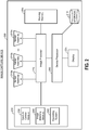
- Figure 2 depicts a high-level block diagram of a device 200 having a set of components including an image processor 220 linked to one or more cameras 215a-n.
- the image processor 220 is also in communication with a working memory 205, memory component 230, and device processor 250, which in turn is in communication with storage 210 and electronic display 225.
- Device 200 may be a cell phone, digital camera, tablet computer, personal digital assistant, or the like. There are many portable computing devices in which a reduced thickness imaging system such as is described herein would provide advantages. Device 200 may also be a stationary computing device or any device in which a thin imaging system would be advantageous. A plurality of applications may be available to the user on device 200. These applications may include traditional photographic and video applications, high dynamic range imaging, panoramic photo and video, or stereoscopic imaging such as 3D images or 3D video.
- the image capture device 200 includes the cameras 215a-n for capturing external images.
- the cameras 215a-n may each comprise a sensor, lens assembly, and a primary and secondary reflective or refractive surface for redirecting a portion of a target image to each sensor, as discussed above with respect to Figure 1 .
- N cameras 215a-n may be used, where N ⁇ 2.
- the target image may be split into N portions in which each sensor of the N cameras captures one portion of the target image according to that sensor's field of view.
- cameras 215a-n may comprise any number of cameras suitable for an implementation of the folded optic imaging device described herein.
- the number of sensors may be increased to achieve lower z-heights of the system, as discussed in more detail below with respect to Figure 4 , or to meet the needs of other purposes, such as having overlapping fields of view similar to that of a plenoptic camera, which may enable the ability to adjust the focus of the image after post-processing.
- Other embodiments may have a FOV overlap configuration suitable for high dynamic range cameras enabling the ability to capture two simultaneous images and then merge them together.
- the cameras 215a-n may be coupled to the image processor 220 to communicate captured images to the working memory 205, the device processor 250, to the electronic display 225 and to the storage (memory) 210.
- the image processor 220 may be configured to perform various processing operations on received image data comprising N portions of the target image in order to output a high quality stitched image, as will be described in more detail below.
- Image processor 220 may be a general purpose processing unit or a processor specially designed for imaging applications. Examples of image processing operations include cropping, scaling (e.g., to a different resolution), image stitching, image format conversion, color interpolation, color processing, image filtering (for example, spatial image filtering), lens artifact or defect correction, etc.
- Image processor 220 may, in some embodiments, comprise a plurality of processors. Certain embodiments may have a processor dedicated to each image sensor.
- Image processor 220 may be one or more dedicated image signal processors (ISPs) or a software implementation of a processor.
- ISPs dedicated image signal processors
- the image processor 220 is connected to a memory 230 and a working memory 205.
- the memory 230 stores capture control module 235, image stitching module 240, and operating system 245. These modules include instructions that configure the image processor 220 of device processor 250 to perform various image processing and device management tasks.
- Working memory 205 may be used by image processor 220 to store a working set of processor instructions contained in the modules of memory component 230. Alternatively, working memory 205 may also be used by image processor 220 to store dynamic data created during the operation of device 200.
- the capture control module 235 may include instructions that configure the image processor 220 to adjust the focus position of cameras 215a-n. Capture control module 235 may further include instructions that control the overall image capture functions of the device 200. For example, capture control module 235 may include instructions that call subroutines to configure the image processor 220 to capture raw image data of a target image scene using the cameras 215a-n. Capture control module 235 may then call the image stitching module 240 to perform a stitching technique on the N partial images captured by the cameras 215a-n and output a stitched and cropped target image to imaging processor 220.
- Capture control module 235 may also call the image stitching module 240 to perform a stitching operation on raw image data in order to output a preview image of a scene to be captured, and to update the preview image at certain time intervals or when the scene in the raw image data changes.
- Image stitching module 240 may comprise instructions that configure the image processor 220 to perform stitching and cropping techniques on captured image data. For example, each of the N sensors 215a-n may capture a partial image comprising a portion of the target image according to each sensor's field of view. The fields of view may share areas of overlap, as described above and below. In order to output a single target image, image stitching module 240 may configure the image processor 220 to combine the multiple N partial images to produce a high-resolution target image. Target image generation may occur through known image stitching techniques.
- image stitching module 240 may include instructions to compare the areas of overlap along the edges of the N partial images for matching features in order to determine rotation and alignment of the N partial images relative to one another. Due to rotation of partial images and/or the shape of the FOV of each sensor, the combined image may form an irregular shape. Therefore, after aligning and combining the N partial images, the image stitching module 240 may call subroutines which configure image processor 220 to crop the combined image to a desired shape and aspect ratio, for example a 4:3 rectangle or 1:1 square. The cropped image may be sent to the device processor 250 for display on the display 225 or for saving in the storage 210.
- Operating system module 245 configures the image processor 220 to manage the working memory 205 and the processing resources of device 200.
- operating system module 245 may include device drivers to manage hardware resources such as the cameras 215a-n. Therefore, in some embodiments, instructions contained in the image processing modules discussed above may not interact with these hardware resources directly, but instead interact through standard subroutines or APIs located in operating system component 270. Instructions within operating system 245 may then interact directly with these hardware components. Operating system module 245 may further configure the image processor 220 to share information with device processor 250.
- Device processor 250 may be configured to control the display 225 to display the captured image, or a preview of the captured image, to a user.
- the display 225 may be external to the imaging device 200 or may be part of the imaging device 200.
- the display 225 may also be configured to provide a view finder displaying a preview image for a use prior to capturing an image, or may be configured to display a captured image stored in memory or recently captured by the user.
- the display 225 may comprise an LCD or LED screen, and may implement touch sensitive technologies.
- Device processor 250 may write data to storage module 210, for example data representing captured images. While storage module 210 is represented graphically as a traditional disk device, those with skill in the art would understand that the storage module 210 may be configured as any storage media device.
- the storage module 210 may include a disk drive, such as a floppy disk drive, hard disk drive, optical disk drive or magneto-optical disk drive, or a solid state memory such as a FLASH memory, RAM, ROM, and/or EEPROM.
- the storage module 210 can also include multiple memory units, and any one of the memory units may be configured to be within the image capture device 200, or may be external to the image capture device 200.
- the storage module 210 may include a ROM memory containing system program instructions stored within the image capture device 200.
- the storage module 210 may also include memory cards or high speed memories configured to store captured images which may be removable from the camera.
- Figure 2 depicts a device having separate components to include a processor, imaging sensor, and memory
- processor imaging sensor
- memory memory components
- Figure 2 illustrates two memory components, including memory component 230 comprising several modules and a separate memory 205 comprising a working memory
- memory component 230 comprising several modules
- a separate memory 205 comprising a working memory
- a design may utilize ROM or static RAM memory for the storage of processor instructions implementing the modules contained in memory component 230.
- the processor instructions may be loaded into RAM to facilitate execution by the image processor 220.
- working memory 205 may comprise RAM memory, with instructions loaded into working memory 205 before execution by the processor 220.
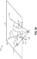
- Figure 3A is a schematic illustrating camera 310A, 310B, 310C and mirror plane 312A, 312B, 312C locations in a parallax free array camera 300A, according to some embodiments.
- a sensor of the array and its corresponding lens (and possible additional light folding surface or surfaces) is referred to herein as a "camera,” and the cooperation of all cameras in the array is referred to herein as a "virtual camera.”
- a camera can be modelled as a point, that is a center of projection of its associated lens assembly, which center of projection can be located anywhere in xyz space.
- An array of cameras is modelled by an array of such centers of projection.
- a virtual camera is the location from which an image captured by a camera, for example the image captured by 310A, appears to have been captured if no optical folding (e.g., reflection using mirrors) had been used.
- all virtual cameras are merged into one single virtual camera having the same center of projection, shown in Figures 3A and 3B as point V.
- Each individual camera of the array may have potentially different direction of gaze, that is a direction or alignment of the optical axis of the camera, which is sometimes referred to as tilt.
- a main point of the spatial relationships described herein for forming parallax free array cameras is that the effective tilt of each virtual camera (for example, the appearance of tilt in the corresponding image) can be changed computationally by application of a projective transform to the captured image data. Stitching the images together after application of proper projective transforms and cropping produces a single image- a composite image of the target scene using data received from the multiple cameras of the array. This single image appears as if it was captured by a single virtual camera with a center of projection at point V, referred to herein as the virtual camera. Accordingly, the virtual camera of the parallax-free arrays as described herein is actually a compound virtual camera and a composition of the multiple virtual cameras merging into a single point.
- the virtual camera as used herein can also be the result of computational synthesis by transforming, cropping, and stitching the individual images each captured by one of the multiple cameras of the array.
- the cameras 310B, 310C, 310E, and 310F are each modeled as a point representing the center of projection for that camera in xyz space.
- a real camera has an entrance pupil having a certain position in space.
- the center of the pupil is referred to herein as the center of projection of the camera and is determined at least partly by the optics of the lens assembly.
- the center of projection may not be where the physical aperture of the camera is located due to optics of the lens assembly, and the real position where the optical center of projection is located is where the center of the pupil is located.
- the captured image transforms as with application of a computational projective transform.
- FIGS. 3A and 3B are an abstraction: the direction of gaze and focal length of a camera are not essential for parallax-free imaging because such aspects can be corrected by projective transform at a later stage (for example, computationally).
- the abstraction of cameras 310B, 310C, 310E, and 310F are illustrated only by a center of projection in this general treatment.
- Use of the center of projection for representing the camera serves the purpose of enabling designing of the array of cameras to form parallax free images.
- Real gaze and focal length of the cameras are important for other aspects of imaging, but the specifics of these aspects can be varied according to the needs of various embodiments of a parallax free array camera.
- Virtual camera V and cameras 310A, 310D are illustrated as a block diagram centered on the point representing the center of projection for each of virtual camera V and cameras 310A, 310D, respectively.
- the array of cameras are positioned in (or at least approximately positioned in) the horizontal plane 305 of the thin camera.
- the term "horizontal" is chosen arbitrarily for the purpose of this discussion, for example, in reference to Figures 3A and 3B .
- the mirror planes 312A-312E are illustrated with boundaries, however the planes extend infinitely and the actual mirror locations could be anywhere within the planes represented by 312A-312E.
- the mirrored surface could connect at angles to form a reflective element having an apex, for example located at or approximately at point P along the optical axis 321 of virtual camera V.
- the apex could be located at other points along the optical axis 321 of the virtual camera V in other examples.
- the planes 312A, 312B, 312C can also be used to position light directing facets of a refractive prism in some embodiments.
- FIG 3A illustrates three cameras 310A, 310B, 310C in the horizontal plane 305 of an array camera and Figure 3B illustrates three cameras 310D, 310E, 310F in the horizontal plane 305.
- each camera 310A, 310B, 310C in Figure 3A may be positioned so the center of the FOV is pointing towards (or approximately pointing towards) a central location P as illustrated by the optical axis 311A of camera 310A.
- the cameras 310D, 310E, and 310F are depicted as pointing horizontally towards central location P.
- Each camera 310D, 310E, 310F can be positioned to be approximately "looking" (as illustrated by optical axis 311B of camera 310D) toward a mirror 330 (illustrated only in reference to camera 310D and mirror plan 312D) positioned in the mirror plane 312D, 312E, 312F corresponding to the camera 310D, 310E, 310F.
- each camera 310D, 310E, 310F can have an optical axis of its projected FOV positioned toward a mirror.
- each camera 310A-F may have a central axis of its projected FOV along the virtual optical axis 321 to receive light propagating from a target scene.
- the direction in which a camera is looking - the alignment of its optical axis - can be a design parameter that may be varied while still complying with the parallax free spatial relationships described herein.
- This generality of the parallax free design principles of Figures 3A and 3B allows for great freedom of design and captures all sorts of array camera configurations.
- optical axis 311A of Figure 3A is illustrated as "looking at" or aligned with point P, the optical axis of a camera is not required to look at point P.
- the optical axis in other examples can look at any point on the line 321 between P and Z or, in other examples, could look in some other direction.
- optical axis 311B of Figure3B shown pointing approximately at the center mirror 330, can be pointed in other directions, for example at an apex of a mirror reflective element formed by the multiple mirrors of the camera.
- Cameras in the arrays 300A having an optical axis aligned with point P, as with illustrated axis 311A, can be rotated around their center of projection to look a little bit below point P along line 321 without physically rotating the actual camera, for instance through computation by taking the original image data from the camera, applying a projective transform, and then cropping the image.
- Such computational rotation can be easily handled digitally (within certain practical limits, for example approximately 10 degrees).
- the general model for parallax-free imaging described herein therefore considers a camera without any specific direction of view, and example optical axes 311A and 311B are provided just for example.
- the parallax-free design principle as illustrated in Figures 3A and 3B is configured such that, after reflection from mirrors located somewhere within the mirror planes 312A-312C and 312D-312F all centers of projection of the cameras 310A-310C and 310D-310F appear as being projected from one (or a single) virtual center V.
- the virtual camera center of projection V is located below the horizontal plane 305 such that the cameras 310A, 310B, 310C cooperate to capture an image as if looking upward along optical axis 321 into an image space above the horizontal plane 305, where below and upward are terms chosen arbitrarily to refer to the relative positions of the cameras 310A, 310B, 310C, virtual camera center of projection V, and image space, and are not intended to constrain the positioning or orientation of the actual camera in real space.
- the actual mirrors located within planes 312A, 312B, 312C can intersect to form a reflective element with its apex positioned above its base.
- the apex can be located at point P and the base of the reflective element can be located somewhere along the optical axis 321 towards the virtual camera V.
- the embodiment 300B of Figure 3B represents a wide FOV array camera.
- the virtual camera center of projection V is located above the horizontal plane 305 such that the cameras 310D, 310E, 310F cooperate to capture a wide FOV image as if looking outward away from optical axis 321 into an image space around the horizontal plane 305, where below and upward are terms chosen arbitrarily to refer to the relative positions of the cameras 310D, 310E, 310F, virtual camera center of projection V, and image space, and are not intended to constrain the positioning or orientation of the actual camera in real space.
- the actual mirrors located within planes 312D, 312E, 312F can intersect to form a reflective element with its apex positioned below its base.
- the apex can be located at point P and the base of the reflective element can be located somewhere along the optical axis 321 towards the virtual camera V.
- a reflecting reflective element for the wide FOV embodiment 300B is inverted in comparison with a reflecting reflective element for the embodiment 300A.
- the array 300A "sees” an image located along optical axis 321
- the array 300B "sees” a 180 degree panoramic image of a space located circumferentially around axis 321 but does not see the central image scene that is seen by array 300A.
- the designs 300A and 300B can be combined to form a camera that captures a full hemispheric field of view.
- the designer or manufacturer can locate the middle 314A, 314B, 314C of each segment 313A, 313B, 313C and place the plane 312A, 312B, 312C of a mirror at the middle or substantially at the middle 314A, 314B, 314C and orthogonal or substantially orthogonal to that segment.
- a designer or manufacturer can locate point V (the center of projection for the virtual camera) anywhere above the horizontal plane 305 of the array camera 300B. The designer or manufacturer can then set or identify the locations of cameras 310D, 310E, 310F and then create lines 313D, 313E, 313F connecting the center of projection of each camera with the center of projection of the virtual camera.
- the designer or manufacturer can locate the middle 314D, 314E, 314F of each segment 313D, 313E, 313F and place the plane 312D, 312E, 312F of a mirror at the middle 314D, 314E, 314F and orthogonal to that segment.
- a mirror 330 can be placed anywhere in its corresponding plane 312D.
- each plane 312A-312F is illustrated with a boundary, in theory a plane is infinite, and the designer can choose the appropriate size and location of a mirror within its corresponding plane according to the needs of the particular camera construction, for example to prevent overlapping mirrors, obstruction of a camera's field of view, etc. Reflections from those mirrors send each center of projection (in this case of cameras 310A-310F) to the same virtual center of projection V of the thin camera 300A, 300B. This ensures no or substantially no parallax in the resulting stitched image between the fields of view of the cameras.
- the mirrors located within planes 312A-312C and 312D-312F can be arranged to form a reflective element.
- planes 312A-312C can be extended outward from the illustrated boundaries until they intersect to form a reflective element with an apex at or near point P having mirrored facets sloping downward and outward.
- planes 312D-312F can be extended outward from the illustrated boundaries until they intersect to form a reflective element with an apex at or near point P having mirrored facets sloping upward and outward.
- a reflecting reflective element for the embodiment 300B is inverted in comparison with a reflecting reflective element for the embodiment 300A.
- mirrors do not have to be positioned in the locations shown for planes 312A-312F and the actual mirrors do not have to be located along the lines 313A-313F or containing midpoints 314A-314F, but rather can be located anywhere in the infinitely extended plane.
- FIGS. 3A and 3B include three cameras, however the parallax-free design principle works for any number of cameras.
- the exact viewing direction of the individual cameras is not related to the issue of parallax, but is related to efficiency and artifacts of tilt, etc.
- Such distortions in the images resulting from different viewing direction of cameras can be undone digitally with the well-known projective transform, applied after the fact.
- This correction is exact for infinitely small apertures and approximately exact for small finite apertures, for example, apertures that may typically be used in imaging systems of mobile device (for example, cell phone, tablets, etc.).
- Projective transform correction can be remove all or substantially all tilt artifacts by applying an appropriate projective transform (which is actually predefined given the positioning of the mirror plane and the camera).
- all cameras of the array may be positioned in the horizontal plane of (or physically inside the) thin camera module or camera housing. However, in other embodiments the cameras do not have to be positioned in the horizontal plane 305. For example, the cameras do not have to be positioned in the horizontal plane for a spherical camera, or for a free "3D cloud of centers" camera arrangement. In some array camera embodiments, the arrangement of the cameras may be symmetric, or substantially symmetric, so that all mirror planes have one common point of intersection. If such point exists, it is denoted P in the figures, as in Figures 3A and 3B . The plurality of mirrors can form a reflective element with apex P.
- pyramid or reflective element can refer to any three-dimensional shape having a number of facets each extending upwardly at angle from a base with some or all facets meeting at apex P. In other cases there may be no point common to all mirrors.. In the described embodiments, however the design is free (or substantially free) of parallax artifacts because all virtual cameras (the images of real cameras after folding) see the world from a common virtual center of projection V, regardless of orientation.
- the virtual center of projection refers to the center projection of the virtual camera location from which the projected field-of-view (FOV) cones of all of the cameras in the array appear to originate, even after re-directing or folding of the incoming light (for example by mirrors or refractive prisms).
- FOV field-of-view
- a defocus blur kernel can be created, in order to compensate at least partially for the defocus blur, from the common aperture that is synthesized from all camera apertures/mirrors. If there are gaps and irregularities at certain locations or directions in the view from the location of V, blur will appear unnatural. This is due to the fact that real individual cameras are not really points, but apertures each representing an area of a surface with orientation in 3D space. However, designs with insufficient symmetry may still be used for capturing good quality images of scenes that are almost completely in focus, or if there are no objects particularly close to the array camera, for example, from approximately 20 cm to approximately 50 cm from the camera, in some implementations.
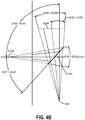
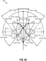
- Figures 4A through 4C illustrate an embodiment of an array camera 400 designed according to the parallax-free design principle illustrated in Figures 3A and 3B .
- Figure 4A illustrates an array with two-cameras 410A, 410B.
- the cameras 410A, 410B each have a viewing angle of approximately 20 degrees, resulting in an effective viewing angle of approximately 26 degrees for the combined array camera 400.
- the cameras 410A, 410B appear to capture image data from the same apparent origin 450.
- the view 420A, 420B that is observed by each cameras 410A, 410 is highlighted in blue dashed lines. For purposes of clarity lens assemblies and secondary reflecting or refracting surfaces are not illustrated in cameras 410A, 410B.
- sensors of cameras 410A, 410B may be aligned with light following initial reflection or refraction, however in other embodiments secondary reflective or refractive surface may be used, for example to reduce the overall height of the array by placing the sensors of cameras 410A, 410B within or substantially within a common plane.
- Figure 4B illustrates one example of design parameters for viewing angle 420Aand mirror surface 415Afor the camera 410Aof Figure 4A .
- the individual cameras 410A, 410B each should have a FOV having a viewing angle 420A, 420B of at least approximately 48 degrees.
- Figure 4C illustrates an example of design parameters for both viewing angle 420A, 420B and mirror surfaces 415A, 415B for the cameras 410A, 410B of Figure 4A to achieve a 60 degree viewing angle.
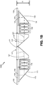
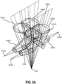
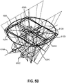
- Figures 5A and 5B illustrate an embodiment of a four-camera 610A-610D array camera 600 designed according to the parallax-free design principle illustrated in Figures 3A and 3B .
- Figure 5A illustrates an isometric view of the four-camera 610A-610D array camera 600 created by mirroring of the FOV of a single camera about two planes. For purposes of clarity lens assemblies and secondary reflecting or refracting surfaces are not illustrated in cameras 610A-610D.
- sensors of cameras 610A-610D may be aligned with light following initial reflection or refraction, however in other embodiments secondary reflective or refractive surface may be used, for example to reduce the overall height of the array by placing the sensors of cameras 610A-610D within or substantially within a common plane.
- Cones 625A-625D are the cones of the FOV as seen by the lens of the cameras 610A-610D.
- the cones 630A, 630C, 630D (note: cone 630B not illustrated for clarity of the figure) are the cones of the FOV as seen by the sensor of the cameras 610A-610D.
- the location of the mirror planes 312D-312F (illustrated in Figure 3B and generally as mirror plans 615 in Figure 5B ) as specified by the parallax-free design parameters described above with respect to Figures 3A and 3B determines in part the shape of the final image and the amount of overlap between images captured by the cameras 610A-610D (the angle of the reflective surface positioned within mirror planes 615 is also a factor).
- the location of the mirror planes 312D-312F (illustrated in Figure 3B and illustrated generally as mirror planes 615 in Figure 5A ) as specified by the parallax-free design parameters described above with respect to Figures 3A and 3B determines in part the shape of the final image and the amount of overlap between images captured by the cameras 610A-610D (the angle of the reflective surface positioned within mirror planes 615 is also a factor).
- the illustrated four-camera array camera 600 was designed without significant overlap between the FOV of the cameras, however this can be achieved in one embodiment by rotating adjacent cameras about their optical axis, as the optical axes of the cameras reside in the same plane.
- overlap can be created between adjacent cameras by rotating them toward the virtual optical axis until they are back in an un-rotated position.
- placing the cameras parallel to each other can cause overlap to increase with increasing object distance while the non-overlapping area will not increase at increasing object distance (the percentage overlap will approach 100%), and therefore may not be a workable solution in certain embodiments.
- Rotating the cameras slightly toward the centerline to create some overlap can result in an overlap of approximately 10 degrees in each direction.
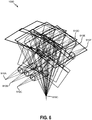
- Figure 6 illustrates an embodiment of an array camera 1000 designed according to the parallax-free design principle illustrated in Figures 3A and 3B .
- the camera of Figure 6 is a six-camera 910A-910F array camera constructed by extending the four-camera array camera to include an additional two cameras and two mirrored surfaces.
- the cameras 910A-910F in this embodiment can be rotated due to space constraints.
- FIG. 7 illustrates an embodiment of a folded optic image capture process 900.
- the process 900 begins at block 905, in which a plurality of imaging sensor assemblies are provided.
- This block includes any of the sensor array configurations discussed above with respect to the previous images, wherein the sensors and associated light folding surfaces are arranged according to the parallax free design concepts disclosed herein.
- the sensor assemblies may include, as discussed above, a sensor, lens system, and a refractive or reflective surface positioned to redirect light from the lens system onto the sensor.
- the process 900 then moves to block 910, in which at least one refractive or reflective surface is mounted proximate to the plurality of image sensors.
- this block could comprise mounting a central mirror reflective element between two rows of sensor arrays, wherein the central mirror reflective element comprises a surface associated with each sensor in the arrays.
- the process 900 then transitions to block 915, in which light comprising a target image of a scene is reflected off of the at least one reflective surface toward the imaging sensors. For example, a portion of the light may be refracted by or reflected off of each of a plurality of surfaces toward each of the plurality of sensors.
- This block may further comprise passing the light through a lens assembly associated with each sensor, and may also include reflecting the light off of a second surface onto a sensor.
- Block 915 may further comprise focusing the light using the lens assembly or through movement of any of the reflective surfaces.
- the process 900 may then move to block 920, in which the sensors capture a plurality of images of the target image scene.
- each sensor may capture an image of a portion of the scene corresponding to that sensor's field of view.
- the fields of view of the plurality of sensors cover at least the target image in the object space.
- projective transforms can be applied to some or all of the captured images in order to digitally rotate the optical axis of the camera used to capture the image.
- the process 900 then may transition to block 925 in which an image stitching method is performed to generate a single image from the plurality of images.
- the image stitching module 240 of Figure 2 may perform this block. This may include known image stitching techniques. Further, any areas of overlap in the fields of view may generate overlap in the plurality of images, which may be used in aligning the images in the stitching process.
- block 925 may further include identifying common features in the overlapping area of adjacent images and use the common features to align the images.
- the process 900 transitions to block 930 in which the stitched image is cropped to a specified aspect ratio, for example 4:3 or 1:1.
- the process ends after storing the cropped image at block 935.
- the image may be stored in storage 210 of Figure 2 , or may be stored in working memory 205 of Figure 2 for display as a preview image of the target scene.
- Implementations disclosed herein provide systems, methods and apparatus for multiple aperture array cameras free from parallax and tilt artifacts.
- One skilled in the art will recognize that these embodiments may be implemented in hardware, software, firmware, or any combination thereof.
- the circuits, processes, and systems discussed above may be utilized in a wireless communication device.
- the wireless communication device may be a kind of electronic device used to wirelessly communicate with other electronic devices. Examples of wireless communication devices include cellular telephones, smart phones, Personal Digital Assistants (PDAs), e-readers, gaming systems, music players, netbooks, wireless modems, laptop computers, tablet devices, etc.
- the wireless communication device may include one or more image sensors, two or more image signal processors, a memory including instructions or modules for carrying out the processes discussed above.
- the device may also have data, a processor loading instructions and/or data from memory, one or more communication interfaces, one or more input devices, one or more output devices such as a display device and a power source/interface.
- the wireless communication device may additionally include a transmitter and a receiver.
- the transmitter and receiver may be jointly referred to as a transceiver.
- the transceiver may be coupled to one or more antennas for transmitting and/or receiving wireless signals.
- the wireless communication device may wirelessly connect to another electronic device (e.g., base station).
- a wireless communication device may alternatively be referred to as a mobile device, a mobile station, a subscriber station, a user equipment (UE), a remote station, an access terminal, a mobile terminal, a terminal, a user terminal, a subscriber unit, etc.
- Examples of wireless communication devices include laptop or desktop computers, cellular phones, smart phones, wireless modems, e-readers, tablet devices, gaming systems, etc.
- Wireless communication devices may operate in accordance with one or more industry standards such as the 3rd Generation Partnership Project (3GPP).
- 3GPP 3rd Generation Partnership Project
- the general term "wireless communication device” may include wireless communication devices described with varying nomenclatures according to industry standards (e.g., access terminal, user equipment (UE), remote terminal, etc.).
- Disk and disc includes compact disc (CD), laser disc, optical disc, digital versatile disc (DVD), floppy disk and Blu-ray® disc where disks usually reproduce data magnetically, while discs reproduce data optically with lasers.
- a computer-readable medium may be tangible and non-transitory.
- computer-program product refers to a computing device or processor in combination with code or instructions (e.g., a "program”) that may be executed, processed or computed by the computing device or processor.
- code may refer to software, instructions, code or data that is/are executable by a computing device or processor.
- Software or instructions may also be transmitted over a transmission medium.
- a transmission medium For example, if the software is transmitted from a website, server, or other remote source using a coaxial cable, fiber optic cable, twisted pair, digital subscriber line (DSL), or wireless technologies such as infrared, radio, and microwave, then the coaxial cable, fiber optic cable, twisted pair, DSL, or wireless technologies such as infrared, radio, and microwave are included in the definition of transmission medium.
- DSL digital subscriber line
- the methods disclosed herein comprise one or more steps or actions for achieving the described method.
- the method steps and/or actions may be interchanged with one another without departing from the scope of the claims.
- the order and/or use of specific steps and/or actions may be modified without departing from the scope of the claims.
- Couple may indicate either an indirect connection or a direct connection.
- first component may be either indirectly connected to the second component or directly connected to the second component.
- plurality denotes two or more. For example, a plurality of components indicates two or more components.
- determining encompasses a wide variety of actions and, therefore, “determining” can include calculating, computing, processing, deriving, investigating, looking up (e.g., looking up in a table, a database or another data structure), ascertaining and the like. Also, “determining” can include receiving (e.g., receiving information), accessing (e.g., accessing data in a memory) and the like. Also, “determining” can include resolving, selecting, choosing, establishing and the like.
- examples may be described as a process, which is depicted as a flowchart, a flow diagram, a finite state diagram, a structure diagram, or a block diagram.
- a flowchart may describe the operations as a sequential process, many of the operations can be performed in parallel, or concurrently, and the process can be repeated. In addition, the order of the operations may be rearranged.
- a process is terminated when its operations are completed.
- a process may correspond to a method, a function, a procedure, a subroutine, a subprogram, etc.
- a process corresponds to a software function
- its termination corresponds to a return of the function to the calling function or the main function.
Description
- The present disclosure relates to imaging systems and methods that include a multi-camera array. In particular, the disclosure relates to systems and methods that enable low-profile imaging systems of mobile devices while maintaining or improving image quality.
- Many mobile devices, such as mobile phones and tablet computing devices, include cameras that may be operated by a user to capture still and/or video images. Because the mobile devices are typically designed to be relatively small, it can be important to design the cameras or imaging systems to be as thin as possible in order to maintain a low-profile mobile device. Folded optic image sensor arrays ("array cameras") allow for the creation of low-profile image capture devices without shortening the focal length or decreasing the resolution of the image across the sensor array's field of view. By redirecting light toward each sensor in the array using a primary and secondary surface, and by positioning the lens assemblies used to focus the incoming light between the primary and secondary surfaces, the sensor array may be positioned on a flat substrate perpendicular to the lens assemblies. The longer focal length makes it possible to implement features such as optical zoom and to incorporate more complicated optics that require more space than commonly afforded by the traditional mobile camera, such as adding more optical elements.
- Some array cameras employ a central mirror or prism with multiple facets to split incoming light comprising the target image into multiple portions for capture by the sensors in the array, wherein each facet directs a portion of the light from the target image toward a sensor in the array. Each portion of the split light may be passed through a lens assembly and reflected off of an additional surface positioned directly above or below a sensor, such that each sensor captures a portion of the image. The sensor fields of view can overlap to assist in stitching together the captured portions into a complete image. Examples of conventional array cameras are disclosed in
WO 2012/136388 ,US 20033214575 ,US 2004021767 ,EP 0751416 ,US 2014111650 andUS 2006023106 . - The folded optic sensor arrays and image capture techniques described herein allow for the creation of low-profile image capture devices without shortening the focal length or decreasing the resolution of the image across the sensor array's field of view, and the captured images are free (or nearly so) of parallax artifacts. A challenge of array cameras is the quality degradation due to parallax between different views of same object as seen from different cameras of the array. Parallax prevents seamless stitching of the images captured by each camera into a final image completely free of artifacts. Camera views can partially overlap (for example by approximately 20%). Depending on the depth of the scene of in an image (e.g., distance from lens to object(s)) the image from one camera can be shifted relative to the image from another camera. The resulting parallax and tilt can cause "double image" ghosting in the image area corresponding to the overlapping fields of view when the images are stitched or fused together. Even if the array is structured such that there is no overlap in sensor fields of view, parallax results in discontinuous features in the image, such as lines and edges, when such features cross over the borders between sensor fields of view.
- The above-described problems, among others, are addressed in various embodiments by the array cameras free of parallax and tilt artifacts as described herein. Some of the embodiments may employ a central mirror or prism, for example with multiple surfaces or facets, to split incoming light comprising the target image into multiple portions for capture by the sensors in the array. The mirror surfaces and sensors can be configured to avoid causing parallax and tilt artifacts in a captured image. For example, the planes of the central mirror surfaces of the array camera can be located at a midpoint along, and orthogonal to, a line between the corresponding camera location and the virtual camera location. Accordingly, the projected field-of-view (FOV) cones of all of the cameras in the array appear as if coming from the virtual camera location after folding of the incoming light by the mirrors.
- Each portion of the split light may be passed through a lens assembly and reflected off of an optionally additional reflective surface positioned directly above or below a sensor, such that each sensor captures a portion of the image. In some circumstances, each sensor in the array may capture a portion of the image which overlaps slightly with the portions captured by neighboring sensors in the array, and these portions may be assembled into the target image, for example by linear blending or other image stitching techniques.
- One innovation includes a system, as defined in independent claim 1, for capturing a target image of a scene, the system including an array of a plurality of cameras having a virtual center of projection, each of the plurality of cameras configured to capture one of a plurality of portions of a target image of a scene, and each of the plurality of cameras including an image sensor, a lens assembly including at least one lens, the lens assembly having a center of projection, the lens assembly positioned to focus light on the image sensor, the center of projection of the lens assembly located along a line passing through the virtual center of projection, and a mirror located with respect to the lens assembly to provide light to the lens assembly, the mirror further positioned on (or within) a mirror plane, (sometime referred herein as a "mirror plane"), the mirror plane positioned to intersect a point (for example, a midpoint) long the line passing through the virtual center of projection. The mirror plan may be positioned an angle orthogonal to the line. Various embodiments may include additional features.
- The following are non-limiting examples of some features and embodiments of such systems. For example, the system may further include a central reflective element (for example, a pyramid-shaped reflective component) including a plurality of primary light re-directing surfaces configured to split light representing the target image of the scene into the plurality of portions, the mirror of each of the plurality of cameras forming one of the primary light folding surfaces. The central reflective element may include an apex formed by an intersection of each of the plurality of primary light re-directing surfaces. An optical axis of each of the plurality of cameras may pass through the apex. The apex and the virtual center of projection are located on a virtual optical axis passing through the apex and the virtual center of projection such that the virtual optical axis forms an optical axis of the array of the plurality of cameras. The system may further include a camera housing comprising at least an upper surface having an aperture positioned to allow light representing the scene to pass through the aperture to the central reflective element. The upper surface may be positioned orthogonal to the virtual optical axis at or above the apex of the central reflective element. The housing may further include a lower surface positioned substantially parallel to the upper surface and positioned at or below a lower surface of the central reflective element. Each of the plurality of cameras may be positioned between the upper surface and the lower surface of the camera housing. The system may further include a processor configured to receive image data comprising an image of a portion of the scene from each of the plurality of cameras and to perform a stitching operation to generate the target image. The system may further (for example, to correct tilt artifacts in the image data) include a processor that is further configured to perform a projective transform on the image data based at least partly a geometric relationship between the virtual center of projection and the center of projection of the lens assembly of each of the plurality of cameras and the location of the mirror for each of the plurality of cameras within a corresponding mirror plane. The system may further include a secondary light re-directing surface associated with each of the plurality of cameras, the secondary light re-directing surface positioned to direct light received from the lens assembly onto the image sensor. The system may further include a substrate having at least one aperture, the at least one aperture positioned to allow light representing the scene to pass through the at least one aperture to the mirror of each of the plurality of cameras, wherein the image sensor for each of the plurality of cameras is positioned on or within the substrate.
- Another innovation includes a method, as defined in independent claim 10 of manufacturing an array camera substantially free of parallax artifacts in a captured image. In various embodiments, the method includes positioning a plurality of cameras in an array, each of the plurality of cameras configured to capture one of a plurality of portions of a target image scene, the plurality of cameras positioned to each capture image data from a location of a virtual camera having a virtual center of projection, each of the plurality of cameras including a lens assembly having at least one lens, a camera center of projection having a location determined at least partly by optics of the lens assembly, and a sensor positioned to receive light from the lens assembly. The method may further include providing, for each of the plurality of cameras, a mirror positioned on a mirror plane, the mirror plane positioned to intersect a point (for example, a midpoint) along a line connecting a center of projection of the camera and captured virtual center of projection. The mirror plane may be positioned orthogonally to the line.
- The following are non-limiting examples of some features and embodiments of such method. For example, the method may further include providing the mirror for each of the plurality of cameras as a facet of a central reflective element, the plurality of cameras positioned around the central reflective element or reflective component. The method may include providing the central reflective element such that the mirror for each of the plurality of cameras intersects at an apex of the central reflective element. The method may include positioning each of the plurality of cameras such that an optical axis of each of the plurality of cameras intersects with the apex. The method may include providing a secondary light folding surface for each of the plurality of cameras. The method may include positioning the secondary light folding surface between the lens assembly and the sensor to direct light received from the lens assembly onto the sensor. The method may include providing a substrate having at least one aperture positioned to allow light representing the scene to pass through the aperture to the mirror for each of the plurality of cameras. The method may include mounting the sensor for each of the plurality of cameras on or within the substrate such that all sensors are positioned on (or within) the same plane. The method may include providing a processor in electronic communication with the sensor of each of the plurality of cameras, the processor configured to receive the plurality of portions of a target image scene and generate a complete image of the target image scene.
- The disclosed aspects will hereinafter be described in conjunction with the appended drawings, provided to illustrate and not to limit the disclosed aspects, wherein like designations denote like elements.
-
Figure 1A illustrates a cross-sectional side view of an embodiment of a folded optic sensor assembly. -
Figure 1B illustrates a cross-sectional side view of another embodiment of a folded optic sensor assembly. -
Figure 2 illustrates a block diagram of one embodiment of an image capture device. -
Figures 3A and3B illustrate two embodiments of camera center of projection and mirror plane locations in a parallax free array camera. -
Figures 4A through 4C illustrate an embodiment of an array camera free of parallax artifacts. -
Figure 5A illustrates an embodiment of an array camera free of parallax artifacts. -
Figure 5B illustrates an alternate embodiment of the camera ofFigure 5A that is not free of parallax artifacts. -
Figure 6 illustrates an embodiment of a parallax free array camera. -
Figure 7 illustrates an embodiment of a folded optic image capture process. - Implementations disclosed herein provide systems, methods and apparatus for generating images substantially free of parallax artifacts using an array camera with folded optics. Aspects of the present disclosure relate to an array camera exhibiting little or no parallax artifacts in the captured images. For example, the planes of the central mirror surfaces of the array camera can be located at a midpoint along, and orthogonally to, a line between the corresponding camera location and the virtual camera location. Accordingly, the cones of all of the cameras in the array appear as if coming from the virtual camera location after folding by the mirrors. Each sensor in the array "sees" a portion of the image scene using a corresponding facet of the central mirror prism, and accordingly each individual sensor/mirror pair represents only a sub-aperture of the total array camera. The complete array camera has a synthetic aperture generated based on the sum of all individual aperture rays, that is, based on stitching together the images generated by the sub-apertures.
- In the following description, specific details are given to provide a thorough understanding of the examples. However, the examples may be practiced without these specific details.
- Referring now to
Figures 1A and1B , examples of a folded opticmulti-sensor assembly Figure 1A illustrates a cross-sectional side view of an example of a folded opticmulti-sensor assembly 100A includingimage sensors lens assemblies reflective surface 120 which may all be mounted to asubstrate 150.Figure 1B illustrates a cross-sectional side view of an embodiment of a folded optic multi-sensor assembly includingcentral prisms prisms - Referring to
Figure 1A , theimage sensors sensor Image sensors Sensors - The
sensors substrate 150 as shown inFigure 1A . In some embodiments, all sensors may be on one plane by being mounted to theflat substrate 150.Substrate 150 may be any suitable substantially flat material. The centralreflective surface 120 andlens assemblies substrate 150 as well. Multiple configurations are possible for mounting a sensor array or arrays, a plurality of lens assemblies, and a plurality of primary and secondary reflective or refractive surfaces. - In some embodiments, a central
reflective surface 120 may be used to redirect light from a target image scene toward thesensors reflective surface 120 may be a mirror or a plurality of mirrors, and may be flat or shaped as needed to properly redirect incoming light to theimage sensors reflective surface 120 may be a mirror sized and shaped to reflect incoming light rays through thelens assemblies sensors reflective surface 120 may split light comprising the target image into multiple portions and direct each portion at a different sensor. For example, afirst side 122 of the central reflective surface 120 (also referred to as a primary light folding surface, as other embodiments may implement a refractive prism rather than a reflective surface) may send a portion of the light corresponding to a first field of view (FOV) 140 toward theleft sensor 105 while asecond side 124 sends a second portion of the light corresponding to asecond FOV 145 toward theright sensor 125. It should be appreciated that together the fields ofview - In some embodiments in which the receiving sensors are each an array of a plurality of sensors, the central reflective surface may be made of multiple reflective surfaces angled relative to one another in order to send a different portion of the target image scene toward each of the sensors. Each sensor in the array may have a substantially different field of view, and in some embodiments the fields of view may overlap. Certain embodiments of the central reflective surface may have complicated non-planar surfaces to increase the degrees of freedom when designing the lens system. Further, although the central surface is discussed as being a reflective surface, in other embodiments the central surface may be refractive. For example, the central surface may be a prism configured with a plurality of facets, where each facet directs a portion of the light comprising the scene toward one of the sensors.
- After being reflected off the central
reflective surface 120, at least a portion of incoming light may propagate through each of thelens assemblies more lens assemblies reflective surface 120 and thesensors reflective surfaces lens assemblies - In some embodiments, each lens assembly may comprise one or more lenses and an actuator for moving the lens among a plurality of different lens positions through a housing. The actuator may, for example, be a voice coil motor (VCM), micro-electronic mechanical system (MEMS), or a shape memory alloy (SMA). The lens assembly may further comprise a lens driver for controlling the actuator.
- In some embodiments, traditional auto focus techniques may be implemented by changing the focal length between the
lens corresponding sensor - Multiple side reflective surfaces, for example,
reflective surfaces central mirror 120 opposite the sensors. After passing through the lens assemblies, the sidereflective surfaces 110, 135 (also referred to as a secondary light folding surface, as other embodiments may implement a refractive prism rather than a reflective surface) can reflect the light (downward, as depicted in the orientation ofFigure 1A ) onto thesensors sensor 105 may be positioned beneathreflective surface 110 andsensor 125 may be positioned beneathreflective surface 135. However, in other embodiments, the sensors may be above the side reflectedsurfaces Figure 1B ). Other suitable configurations of the side reflective surfaces and the sensors are possible in which the light from each lens assembly is redirected toward the sensors. Certain embodiments may enable movement of the sidereflective surfaces - Each sensor's
FOV central mirror 120 associated with that sensor. Mechanical methods may be employed to tilt the mirrors and/or move the prisms in the array so that the FOV of each camera can be steered to different locations on the object field. This may be used, for example, to implement a high dynamic range camera, to increase the resolution of the camera system, or to implement a plenoptic camera system. Each sensor's (or each 3x1 array's) FOV may be projected into the object space, and each sensor may capture a partial image comprising a portion of the target scene according to that sensor's field of view. As illustrated inFigure 1A , in some embodiments, the fields ofview sensor arrays sensor arrays Figure 1A , images may be combined from multiple sensors and sensors may not necessarily be opposing, for example, be symmetrically or asymmetrically arranged. Certain embodiments of the stitching process may employ theoverlap 150 for identifying common features in stitching the partial images together. After stitching the overlapping images together, the stitched image may be cropped to a desired aspect ratio, for example 4:3 or 1:1, to form the final image. In some embodiments, the alignment of the optical elements relating to each FOV are arranged to minimize theoverlap 150 so that the multiple images are formed into a single image with minimal or no image processing required in joining the images. -
Figure 1B illustrates a cross-sectional side view of another embodiment of a foldedoptic array camera 100B. As shown inFigure 1B , asensor assembly 100B includes a pair ofimage sensors substrate 150,lens assemblies sensors light folding surface cover glass image sensors light folding surface 122 ofrefractive prism 141 directs a portion of light from the target image scene alongoptical axis 121 through thelens assembly 115, is redirected off of the secondarylight folding surface 110, passes through thecover glass 106, and is incident upon thesensor 105. The primarylight folding surface 124 ofrefractive prism 146 directs a portion of light from the target image scene along optical axis 123 through thelens assembly 130, is redirected off of the secondarylight folding surface 135, passes through thecover glass 126, and is incident upon thesensor 125. The foldedoptic array camera 100B is illustrative of one array camera embodiment implementing refractive prisms instead of the reflective surfaces of thearray camera 100A ofFigure 1A . Each of therefractive prisms substrate 150 such that the primarylight directing surfaces - The
sensors substrate 150 as shown inFigure 1B . In some embodiments, all sensors may be on one plane by being mounted to theflat substrate 150.Substrate 150 may be any suitable substantially flat material. Thesubstrate 150 can include an aperture as described above to allow incoming light to pass through thesubstrate 150 to the primary light folding surfaces 122, 124. Multiple configurations are possible for mounting a sensor array or arrays, as well as the other camera components illustrated, to thesubstrate 150. - Primary light folding surfaces 122, 124 may be prism surfaces as illustrated, or may be a mirror or a plurality of mirrors, and may be flat or shaped as needed to properly redirect incoming light to the
image sensors Figure 1A . The central reflective element may be, for example, an arrangement of a plurality of mirrors or reflective surfaces, or a prism. The reflective element may be pyramid-shaped. The central mirror reflective element, prism, or other reflective surface may split light representing the target image into multiple portions and direct each portion at a different sensor. For example, a primarylight folding surface 122 may send a portion of the light corresponding to a first FOV toward theleft sensor 105 while primarylight folding surface 124 sends a second portion of the light corresponding to a second FOV toward theright sensor 125. In some embodiments in which the receiving sensors are each an array of a plurality of sensors, the light folding surfaces may be made of multiple reflective surfaces angled relative to one another in order to send a different portion of the target image scene toward each of the sensors. It should be appreciated that together the fields of view of the cameras cover at least the target image, and can be aligned and stitched together after capture to form a final image captured by the synthetic aperture of the array. Each sensor in the array may have a substantially different field of view, and in some embodiments the fields of view may overlap. - Other embodiments may combine the reflective and refractive elements illustrated by
Figures 1A and1B . For example, in some embodiments the primary light folding surface may be reflective while the secondary light folding service is refractive, and vice-versa. - As illustrated by
Figures 1A and1B , each array camera has a total height H. In some embodiments, the total height H can be approximately 4.5 mm or less. In other embodiments, the total height H can be approximately 4.0 mm or less. Though not illustrated, theentire array camera - As used herein, the term "camera" refers to an image sensor, lens system, and a number of corresponding light folding surfaces, for example the primary
light folding surface 124,lens assembly 130, secondarylight folding surface 135, andsensor 125 as illustrated inFigure 1 . A folded-optic multi-sensor array, referred to as an "array" or "array camera," can include a plurality of such cameras in various configurations. Some embodiments of array configurations are disclosed inU.S. Application Pub. No. 2014/0111650, filed March 15, 2013 and titled "MULTI-CAMERA SYSTEM USING FOLDED OPTICS". Other array camera configurations that would benefit from the autofocus systems and techniques described herein are possible. -
Figure 2 depicts a high-level block diagram of adevice 200 having a set of components including animage processor 220 linked to one ormore cameras 215a-n. Theimage processor 220 is also in communication with a workingmemory 205,memory component 230, anddevice processor 250, which in turn is in communication withstorage 210 andelectronic display 225. -
Device 200 may be a cell phone, digital camera, tablet computer, personal digital assistant, or the like. There are many portable computing devices in which a reduced thickness imaging system such as is described herein would provide advantages.Device 200 may also be a stationary computing device or any device in which a thin imaging system would be advantageous. A plurality of applications may be available to the user ondevice 200. These applications may include traditional photographic and video applications, high dynamic range imaging, panoramic photo and video, or stereoscopic imaging such as 3D images or 3D video. - The
image capture device 200 includes thecameras 215a-n for capturing external images. Thecameras 215a-n may each comprise a sensor, lens assembly, and a primary and secondary reflective or refractive surface for redirecting a portion of a target image to each sensor, as discussed above with respect toFigure 1 . In general,N cameras 215a-n may be used, where N ≥ 2. Thus, the target image may be split into N portions in which each sensor of the N cameras captures one portion of the target image according to that sensor's field of view. It will be understood thatcameras 215a-n may comprise any number of cameras suitable for an implementation of the folded optic imaging device described herein. The number of sensors may be increased to achieve lower z-heights of the system, as discussed in more detail below with respect toFigure 4 , or to meet the needs of other purposes, such as having overlapping fields of view similar to that of a plenoptic camera, which may enable the ability to adjust the focus of the image after post-processing. Other embodiments may have a FOV overlap configuration suitable for high dynamic range cameras enabling the ability to capture two simultaneous images and then merge them together. Thecameras 215a-n may be coupled to theimage processor 220 to communicate captured images to the workingmemory 205, thedevice processor 250, to theelectronic display 225 and to the storage (memory) 210. - The
image processor 220 may be configured to perform various processing operations on received image data comprising N portions of the target image in order to output a high quality stitched image, as will be described in more detail below.Image processor 220 may be a general purpose processing unit or a processor specially designed for imaging applications. Examples of image processing operations include cropping, scaling (e.g., to a different resolution), image stitching, image format conversion, color interpolation, color processing, image filtering (for example, spatial image filtering), lens artifact or defect correction, etc.Image processor 220 may, in some embodiments, comprise a plurality of processors. Certain embodiments may have a processor dedicated to each image sensor.Image processor 220 may be one or more dedicated image signal processors (ISPs) or a software implementation of a processor. - As shown, the
image processor 220 is connected to amemory 230 and a workingmemory 205. In the illustrated embodiment, thememory 230 stores capturecontrol module 235,image stitching module 240, andoperating system 245. These modules include instructions that configure theimage processor 220 ofdevice processor 250 to perform various image processing and device management tasks. Workingmemory 205 may be used byimage processor 220 to store a working set of processor instructions contained in the modules ofmemory component 230. Alternatively, workingmemory 205 may also be used byimage processor 220 to store dynamic data created during the operation ofdevice 200. - As mentioned above, the
image processor 220 is configured by several modules stored in the memories. Thecapture control module 235 may include instructions that configure theimage processor 220 to adjust the focus position ofcameras 215a-n.Capture control module 235 may further include instructions that control the overall image capture functions of thedevice 200. For example,capture control module 235 may include instructions that call subroutines to configure theimage processor 220 to capture raw image data of a target image scene using thecameras 215a-n.Capture control module 235 may then call theimage stitching module 240 to perform a stitching technique on the N partial images captured by thecameras 215a-n and output a stitched and cropped target image toimaging processor 220.Capture control module 235 may also call theimage stitching module 240 to perform a stitching operation on raw image data in order to output a preview image of a scene to be captured, and to update the preview image at certain time intervals or when the scene in the raw image data changes. -
Image stitching module 240 may comprise instructions that configure theimage processor 220 to perform stitching and cropping techniques on captured image data. For example, each of theN sensors 215a-n may capture a partial image comprising a portion of the target image according to each sensor's field of view. The fields of view may share areas of overlap, as described above and below. In order to output a single target image,image stitching module 240 may configure theimage processor 220 to combine the multiple N partial images to produce a high-resolution target image. Target image generation may occur through known image stitching techniques. - For instance,
image stitching module 240 may include instructions to compare the areas of overlap along the edges of the N partial images for matching features in order to determine rotation and alignment of the N partial images relative to one another. Due to rotation of partial images and/or the shape of the FOV of each sensor, the combined image may form an irregular shape. Therefore, after aligning and combining the N partial images, theimage stitching module 240 may call subroutines which configureimage processor 220 to crop the combined image to a desired shape and aspect ratio, for example a 4:3 rectangle or 1:1 square. The cropped image may be sent to thedevice processor 250 for display on thedisplay 225 or for saving in thestorage 210. -
Operating system module 245 configures theimage processor 220 to manage the workingmemory 205 and the processing resources ofdevice 200. For example,operating system module 245 may include device drivers to manage hardware resources such as thecameras 215a-n. Therefore, in some embodiments, instructions contained in the image processing modules discussed above may not interact with these hardware resources directly, but instead interact through standard subroutines or APIs located in operating system component 270. Instructions withinoperating system 245 may then interact directly with these hardware components.Operating system module 245 may further configure theimage processor 220 to share information withdevice processor 250. -
Device processor 250 may be configured to control thedisplay 225 to display the captured image, or a preview of the captured image, to a user. Thedisplay 225 may be external to theimaging device 200 or may be part of theimaging device 200. Thedisplay 225 may also be configured to provide a view finder displaying a preview image for a use prior to capturing an image, or may be configured to display a captured image stored in memory or recently captured by the user. Thedisplay 225 may comprise an LCD or LED screen, and may implement touch sensitive technologies. -
Device processor 250 may write data tostorage module 210, for example data representing captured images. Whilestorage module 210 is represented graphically as a traditional disk device, those with skill in the art would understand that thestorage module 210 may be configured as any storage media device. For example, thestorage module 210 may include a disk drive, such as a floppy disk drive, hard disk drive, optical disk drive or magneto-optical disk drive, or a solid state memory such as a FLASH memory, RAM, ROM, and/or EEPROM. Thestorage module 210 can also include multiple memory units, and any one of the memory units may be configured to be within theimage capture device 200, or may be external to theimage capture device 200. For example, thestorage module 210 may include a ROM memory containing system program instructions stored within theimage capture device 200. Thestorage module 210 may also include memory cards or high speed memories configured to store captured images which may be removable from the camera. - Although
Figure 2 depicts a device having separate components to include a processor, imaging sensor, and memory, one skilled in the art would recognize that these separate components may be combined in a variety of ways to achieve particular design objectives. For example, in an alternative embodiment, the memory components may be combined with processor components to save cost and improve performance. - Additionally, although
Figure 2 illustrates two memory components, includingmemory component 230 comprising several modules and aseparate memory 205 comprising a working memory, one with skill in the art would recognize several embodiments utilizing different memory architectures. For example, a design may utilize ROM or static RAM memory for the storage of processor instructions implementing the modules contained inmemory component 230. The processor instructions may be loaded into RAM to facilitate execution by theimage processor 220. For example, workingmemory 205 may comprise RAM memory, with instructions loaded into workingmemory 205 before execution by theprocessor 220. -
Figure 3A is aschematic illustrating camera mirror plane free array camera 300A, according to some embodiments. A sensor of the array and its corresponding lens (and possible additional light folding surface or surfaces) is referred to herein as a "camera," and the cooperation of all cameras in the array is referred to herein as a "virtual camera." In the following description of parallax free array camera design principles, a camera can be modelled as a point, that is a center of projection of its associated lens assembly, which center of projection can be located anywhere in xyz space. An array of cameras is modelled by an array of such centers of projection. - A virtual camera is the location from which an image captured by a camera, for example the image captured by 310A, appears to have been captured if no optical folding (e.g., reflection using mirrors) had been used. In a parallax free array physically formed by multiple folded optic cameras, all virtual cameras are merged into one single virtual camera having the same center of projection, shown in
Figures 3A and3B as point V. Each individual camera of the array may have potentially different direction of gaze, that is a direction or alignment of the optical axis of the camera, which is sometimes referred to as tilt. A main point of the spatial relationships described herein for forming parallax free array cameras is that the effective tilt of each virtual camera (for example, the appearance of tilt in the corresponding image) can be changed computationally by application of a projective transform to the captured image data. Stitching the images together after application of proper projective transforms and cropping produces a single image- a composite image of the target scene using data received from the multiple cameras of the array. This single image appears as if it was captured by a single virtual camera with a center of projection at point V, referred to herein as the virtual camera. Accordingly, the virtual camera of the parallax-free arrays as described herein is actually a compound virtual camera and a composition of the multiple virtual cameras merging into a single point. The virtual camera as used herein can also be the result of computational synthesis by transforming, cropping, and stitching the individual images each captured by one of the multiple cameras of the array. - In
Figures 3A and3B , thecameras Figures 3A and3B are an abstraction: the direction of gaze and focal length of a camera are not essential for parallax-free imaging because such aspects can be corrected by projective transform at a later stage (for example, computationally). As such, the abstraction ofcameras - Virtual camera V and
cameras cameras Figure 3A , for a thin camera, as described above, the array of cameras are positioned in (or at least approximately positioned in) thehorizontal plane 305 of the thin camera. The term "horizontal" is chosen arbitrarily for the purpose of this discussion, for example, in reference toFigures 3A and3B . The mirror planes 312A-312E are illustrated with boundaries, however the planes extend infinitely and the actual mirror locations could be anywhere within the planes represented by 312A-312E. In some embodiments the mirrored surface could connect at angles to form a reflective element having an apex, for example located at or approximately at point P along theoptical axis 321 of virtual camera V. The apex could be located at other points along theoptical axis 321 of the virtual camera V in other examples. Though discussed primarily in terms of mirror planes and corresponding mirrored surfaces, theplanes -
Figure 3A illustrates threecameras horizontal plane 305 of an array camera andFigure 3B illustrates threecameras horizontal plane 305. In shown in the illustrated embodiment, eachcamera Figure 3A may be positioned so the center of the FOV is pointing towards (or approximately pointing towards) a central location P as illustrated by theoptical axis 311A ofcamera 310A. InFigure 3B thecameras camera optical axis 311B ofcamera 310D) toward a mirror 330 (illustrated only in reference tocamera 310D andmirror plan 312D) positioned in themirror plane camera camera configurations camera 310A-F and accordingly the light (or cone of rays) received by the camera so that allcameras 310A-F optically look (considering the folding of the light) in a direction (or substantially in a direction) along the virtualoptical axis 321, normal to theplane 305. In other words, eachcamera 310A-F may have a central axis of its projected FOV along the virtualoptical axis 321 to receive light propagating from a target scene. - However, the direction in which a camera is looking - the alignment of its optical axis - can be a design parameter that may be varied while still complying with the parallax free spatial relationships described herein. There are tradeoffs that will be considered in specific designs, for example the direction of gaze of each camera and the location of each camera's center of projection (for example, its distance from the central point P and), each camera's focal length, number of cameras in the array, and whether the array should be symmetric. This generality of the parallax free design principles of
Figures 3A and3B allows for great freedom of design and captures all sorts of array camera configurations. Accordingly, depending on the specific implementation of these parallax free principles, not all light from a mirror positioned in theplane 312A-312F may be incident upon an associatedcamera 310A-310F, however the benefit of this design is that it provides parallax-free images. - Accordingly, though
optical axis 311A ofFigure 3A is illustrated as "looking at" or aligned with point P, the optical axis of a camera is not required to look at point P. The optical axis in other examples can look at any point on theline 321 between P and Z or, in other examples, could look in some other direction. Similarly,optical axis 311B ofFigure3B , shown pointing approximately at thecenter mirror 330, can be pointed in other directions, for example at an apex of a mirror reflective element formed by the multiple mirrors of the camera. Cameras in thearrays 300A having an optical axis aligned with point P, as withillustrated axis 311A, can be rotated around their center of projection to look a little bit below point P alongline 321 without physically rotating the actual camera, for instance through computation by taking the original image data from the camera, applying a projective transform, and then cropping the image. Such computational rotation can be easily handled digitally (within certain practical limits, for example approximately 10 degrees). The general model for parallax-free imaging described herein therefore considers a camera without any specific direction of view, and exampleoptical axes - The parallax-free design principle as illustrated in
Figures 3A and3B is configured such that, after reflection from mirrors located somewhere within the mirror planes 312A-312C and 312D-312F all centers of projection of thecameras 310A-310C and 310D-310F appear as being projected from one (or a single) virtual center V. - In the
embodiment 300A ofFigure 3A , the virtual camera center of projection V is located below thehorizontal plane 305 such that thecameras optical axis 321 into an image space above thehorizontal plane 305, where below and upward are terms chosen arbitrarily to refer to the relative positions of thecameras Figure 3A , the actual mirrors located withinplanes optical axis 321 towards the virtual camera V. - The
embodiment 300B ofFigure 3B represents a wide FOV array camera. The virtual camera center of projection V is located above thehorizontal plane 305 such that thecameras optical axis 321 into an image space around thehorizontal plane 305, where below and upward are terms chosen arbitrarily to refer to the relative positions of thecameras Figure 3B , the actual mirrors located withinplanes mirror 330 inplane 312D) can intersect to form a reflective element with its apex positioned below its base. For example, the apex can be located at point P and the base of the reflective element can be located somewhere along theoptical axis 321 towards the virtual camera V. - As such, a reflecting reflective element for the
wide FOV embodiment 300B is inverted in comparison with a reflecting reflective element for theembodiment 300A. Further, while thearray 300A "sees" an image located alongoptical axis 321, thearray 300B "sees" a 180 degree panoramic image of a space located circumferentially aroundaxis 321 but does not see the central image scene that is seen byarray 300A. In some embodiments, thedesigns - In order to design or construct an array camera free of parallax according to the parallax-free design principle illustrated in
Figure 3A , one can locate point V (the center of projection for the virtual camera) anywhere below thehorizontal plane 305 of thearray camera 300A. The designer or manufacturer can then set or identify the locations ofcameras lines segment plane - In order to design or construct an array camera free of parallax according to the parallax-free design principle illustrated in
Figure 3B , a designer or manufacturer can locate point V (the center of projection for the virtual camera) anywhere above thehorizontal plane 305 of thearray camera 300B. The designer or manufacturer can then set or identify the locations ofcameras lines segment plane Figure 3B , amirror 330 can be placed anywhere in its correspondingplane 312D. - Although each
plane 312A-312F is illustrated with a boundary, in theory a plane is infinite, and the designer can choose the appropriate size and location of a mirror within its corresponding plane according to the needs of the particular camera construction, for example to prevent overlapping mirrors, obstruction of a camera's field of view, etc. Reflections from those mirrors send each center of projection (in this case ofcameras 310A-310F) to the same virtual center of projection V of thethin camera - In some embodiments, the mirrors located within
planes 312A-312C and 312D-312F can be arranged to form a reflective element. For example, planes 312A-312C can be extended outward from the illustrated boundaries until they intersect to form a reflective element with an apex at or near point P having mirrored facets sloping downward and outward. As another example, planes 312D-312F can be extended outward from the illustrated boundaries until they intersect to form a reflective element with an apex at or near point P having mirrored facets sloping upward and outward. As such, a reflecting reflective element for theembodiment 300B is inverted in comparison with a reflecting reflective element for theembodiment 300A. Accordingly, mirrors do not have to be positioned in the locations shown forplanes 312A-312F and the actual mirrors do not have to be located along thelines 313A-313F or containingmidpoints 314A-314F, but rather can be located anywhere in the infinitely extended plane. - The examples illustrated in
Figures 3A and3B include three cameras, however the parallax-free design principle works for any number of cameras. The exact viewing direction of the individual cameras is not related to the issue of parallax, but is related to efficiency and artifacts of tilt, etc. Such distortions in the images resulting from different viewing direction of cameras can be undone digitally with the well-known projective transform, applied after the fact. This correction is exact for infinitely small apertures and approximately exact for small finite apertures, for example, apertures that may typically be used in imaging systems of mobile device (for example, cell phone, tablets, etc.). Projective transform correction can be remove all or substantially all tilt artifacts by applying an appropriate projective transform (which is actually predefined given the positioning of the mirror plane and the camera). - In some thin camera implementations, all cameras of the array may be positioned in the horizontal plane of (or physically inside the) thin camera module or camera housing. However, in other embodiments the cameras do not have to be positioned in the
horizontal plane 305. For example, the cameras do not have to be positioned in the horizontal plane for a spherical camera, or for a free "3D cloud of centers" camera arrangement. In some array camera embodiments, the arrangement of the cameras may be symmetric, or substantially symmetric, so that all mirror planes have one common point of intersection. If such point exists, it is denoted P in the figures, as inFigures 3A and3B . The plurality of mirrors can form a reflective element with apex P. As used herein, the term pyramid or reflective element can refer to any three-dimensional shape having a number of facets each extending upwardly at angle from a base with some or all facets meeting at apex P. In other cases there may be no point common to all mirrors.. In the described embodiments, however the design is free (or substantially free) of parallax artifacts because all virtual cameras (the images of real cameras after folding) see the world from a common virtual center of projection V, regardless of orientation. As used herein, the virtual center of projection refers to the center projection of the virtual camera location from which the projected field-of-view (FOV) cones of all of the cameras in the array appear to originate, even after re-directing or folding of the incoming light (for example by mirrors or refractive prisms). - If symmetry is not sufficient, the array camera design, while producing parallax free images, may still show incorrect defocus blur artifacts. A defocus blur kernel can be created, in order to compensate at least partially for the defocus blur, from the common aperture that is synthesized from all camera apertures/mirrors. If there are gaps and irregularities at certain locations or directions in the view from the location of V, blur will appear unnatural. This is due to the fact that real individual cameras are not really points, but apertures each representing an area of a surface with orientation in 3D space. However, designs with insufficient symmetry may still be used for capturing good quality images of scenes that are almost completely in focus, or if there are no objects particularly close to the array camera, for example, from approximately 20 cm to approximately 50 cm from the camera, in some implementations.
-
Figures 4A through 4C illustrate an embodiment of anarray camera 400 designed according to the parallax-free design principle illustrated inFigures 3A and3B .Figure 4A illustrates an array with two-cameras cameras array camera 400. Thecameras apparent origin 450. Theview cameras 410A, 410 is highlighted in blue dashed lines. For purposes of clarity lens assemblies and secondary reflecting or refracting surfaces are not illustrated incameras cameras cameras -
Figure 4B illustrates one example of design parameters for viewing angle 420Aand mirror surface 415Afor the camera 410AofFigure 4A . To achieve an effective viewing angle of 60 degrees for the synthetic aperture (the sum of all views of thecameras individual cameras viewing angle Figure 4C illustrates an example of design parameters for bothviewing angle mirror surfaces cameras Figure 4A to achieve a 60 degree viewing angle. -
Figures 5A and5B illustrate an embodiment of a four-camera 610A-610D array camera 600 designed according to the parallax-free design principle illustrated inFigures 3A and3B .Figure 5A illustrates an isometric view of the four-camera 610A-610D array camera 600 created by mirroring of the FOV of a single camera about two planes. For purposes of clarity lens assemblies and secondary reflecting or refracting surfaces are not illustrated incameras 610A-610D. In some embodiments, sensors ofcameras 610A-610D may be aligned with light following initial reflection or refraction, however in other embodiments secondary reflective or refractive surface may be used, for example to reduce the overall height of the array by placing the sensors ofcameras 610A-610D within or substantially within a common plane.Cones 625A-625D are the cones of the FOV as seen by the lens of thecameras 610A-610D. Thecones cameras 610A-610D. - The location of the mirror planes 312D-312F (illustrated in
Figure 3B and generally as mirror plans 615 inFigure 5B ) as specified by the parallax-free design parameters described above with respect toFigures 3A and3B determines in part the shape of the final image and the amount of overlap between images captured by thecameras 610A-610D (the angle of the reflective surface positioned within mirror planes 615 is also a factor). - The location of the mirror planes 312D-312F (illustrated in
Figure 3B and illustrated generally as mirror planes 615 inFigure 5A ) as specified by the parallax-free design parameters described above with respect toFigures 3A and3B determines in part the shape of the final image and the amount of overlap between images captured by thecameras 610A-610D (the angle of the reflective surface positioned within mirror planes 615 is also a factor). - As illustrated, there is overlap between the
viewing areas 620A-620D due to skewing of the FOV of eachcamera 610A-610D. The illustrated four-camera array camera 600 was designed without significant overlap between the FOV of the cameras, however this can be achieved in one embodiment by rotating adjacent cameras about their optical axis, as the optical axes of the cameras reside in the same plane. For the adjacent cameras overlap exists in part due to skewing of the FOV of the cameras. This overlap can be larger than shown and can be skewed, as the overlapping area of the left camera is actually reflected from the mirror surface of the right camera and vice versa. - In some embodiments, overlap can be created between adjacent cameras by rotating them toward the virtual optical axis until they are back in an un-rotated position. However, placing the cameras parallel to each other can cause overlap to increase with increasing object distance while the non-overlapping area will not increase at increasing object distance (the percentage overlap will approach 100%), and therefore may not be a workable solution in certain embodiments. Rotating the cameras slightly toward the centerline to create some overlap can result in an overlap of approximately 10 degrees in each direction. However, depending on the size and relative positioning of each camera as well as the height constraints of the array, there may not be enough space available to place two rotated cameras side by side.
-
Figure 6 illustrates an embodiment of anarray camera 1000 designed according to the parallax-free design principle illustrated inFigures 3A and3B . The camera ofFigure 6 is a six-camera 910A-910F array camera constructed by extending the four-camera array camera to include an additional two cameras and two mirrored surfaces. Thecameras 910A-910F in this embodiment can be rotated due to space constraints. -
Figure 7 illustrates an embodiment of a folded opticimage capture process 900. Theprocess 900 begins atblock 905, in which a plurality of imaging sensor assemblies are provided. This block includes any of the sensor array configurations discussed above with respect to the previous images, wherein the sensors and associated light folding surfaces are arranged according to the parallax free design concepts disclosed herein. The sensor assemblies may include, as discussed above, a sensor, lens system, and a refractive or reflective surface positioned to redirect light from the lens system onto the sensor. Theprocess 900 then moves to block 910, in which at least one refractive or reflective surface is mounted proximate to the plurality of image sensors. For example, this block could comprise mounting a central mirror reflective element between two rows of sensor arrays, wherein the central mirror reflective element comprises a surface associated with each sensor in the arrays. - The
process 900 then transitions to block 915, in which light comprising a target image of a scene is reflected off of the at least one reflective surface toward the imaging sensors. For example, a portion of the light may be refracted by or reflected off of each of a plurality of surfaces toward each of the plurality of sensors. This block may further comprise passing the light through a lens assembly associated with each sensor, and may also include reflecting the light off of a second surface onto a sensor.Block 915 may further comprise focusing the light using the lens assembly or through movement of any of the reflective surfaces. - The
process 900 may then move to block 920, in which the sensors capture a plurality of images of the target image scene. For example, each sensor may capture an image of a portion of the scene corresponding to that sensor's field of view. Together, the fields of view of the plurality of sensors cover at least the target image in the object space. Though not illustrated, projective transforms can be applied to some or all of the captured images in order to digitally rotate the optical axis of the camera used to capture the image. - The
process 900 then may transition to block 925 in which an image stitching method is performed to generate a single image from the plurality of images. In some embodiments, theimage stitching module 240 ofFigure 2 may perform this block. This may include known image stitching techniques. Further, any areas of overlap in the fields of view may generate overlap in the plurality of images, which may be used in aligning the images in the stitching process. For example, block 925 may further include identifying common features in the overlapping area of adjacent images and use the common features to align the images. - Next, the
process 900 transitions to block 930 in which the stitched image is cropped to a specified aspect ratio, for example 4:3 or 1:1. Finally, the process ends after storing the cropped image atblock 935. For example, the image may be stored instorage 210 ofFigure 2 , or may be stored in workingmemory 205 ofFigure 2 for display as a preview image of the target scene. - Implementations disclosed herein provide systems, methods and apparatus for multiple aperture array cameras free from parallax and tilt artifacts. One skilled in the art will recognize that these embodiments may be implemented in hardware, software, firmware, or any combination thereof.
- In some embodiments, the circuits, processes, and systems discussed above may be utilized in a wireless communication device. The wireless communication device may be a kind of electronic device used to wirelessly communicate with other electronic devices. Examples of wireless communication devices include cellular telephones, smart phones, Personal Digital Assistants (PDAs), e-readers, gaming systems, music players, netbooks, wireless modems, laptop computers, tablet devices, etc.
- The wireless communication device may include one or more image sensors, two or more image signal processors, a memory including instructions or modules for carrying out the processes discussed above. The device may also have data, a processor loading instructions and/or data from memory, one or more communication interfaces, one or more input devices, one or more output devices such as a display device and a power source/interface. The wireless communication device may additionally include a transmitter and a receiver. The transmitter and receiver may be jointly referred to as a transceiver. The transceiver may be coupled to one or more antennas for transmitting and/or receiving wireless signals.
- The wireless communication device may wirelessly connect to another electronic device (e.g., base station). A wireless communication device may alternatively be referred to as a mobile device, a mobile station, a subscriber station, a user equipment (UE), a remote station, an access terminal, a mobile terminal, a terminal, a user terminal, a subscriber unit, etc. Examples of wireless communication devices include laptop or desktop computers, cellular phones, smart phones, wireless modems, e-readers, tablet devices, gaming systems, etc. Wireless communication devices may operate in accordance with one or more industry standards such as the 3rd Generation Partnership Project (3GPP). Thus, the general term "wireless communication device" may include wireless communication devices described with varying nomenclatures according to industry standards (e.g., access terminal, user equipment (UE), remote terminal, etc.).
- The functions described herein may be stored as one or more instructions on a processor-readable or computer-readable medium. The term "computer-readable medium" refers to any available medium that can be accessed by a computer or processor. By way of example, and not limitation, such a medium may comprise RAM, ROM, EEPROM, flash memory, CD-ROM or other optical disk storage, magnetic disk storage or other magnetic storage devices, or any other medium that can be used to store desired program code in the form of instructions or data structures and that can be accessed by a computer. Disk and disc, as used herein, includes compact disc (CD), laser disc, optical disc, digital versatile disc (DVD), floppy disk and Blu-ray® disc where disks usually reproduce data magnetically, while discs reproduce data optically with lasers. It should be noted that a computer-readable medium may be tangible and non-transitory. The term "computer-program product" refers to a computing device or processor in combination with code or instructions (e.g., a "program") that may be executed, processed or computed by the computing device or processor. As used herein, the term "code" may refer to software, instructions, code or data that is/are executable by a computing device or processor.
- Software or instructions may also be transmitted over a transmission medium. For example, if the software is transmitted from a website, server, or other remote source using a coaxial cable, fiber optic cable, twisted pair, digital subscriber line (DSL), or wireless technologies such as infrared, radio, and microwave, then the coaxial cable, fiber optic cable, twisted pair, DSL, or wireless technologies such as infrared, radio, and microwave are included in the definition of transmission medium.
- The methods disclosed herein comprise one or more steps or actions for achieving the described method. The method steps and/or actions may be interchanged with one another without departing from the scope of the claims. In other words, unless a specific order of steps or actions is required for proper operation of the method that is being described, the order and/or use of specific steps and/or actions may be modified without departing from the scope of the claims.
- It should be noted that the terms "couple," "coupling," "coupled" or other variations of the word couple as used herein may indicate either an indirect connection or a direct connection. For example, if a first component is "coupled" to a second component, the first component may be either indirectly connected to the second component or directly connected to the second component. As used herein, the term "plurality" denotes two or more. For example, a plurality of components indicates two or more components.
- The term "determining" encompasses a wide variety of actions and, therefore, "determining" can include calculating, computing, processing, deriving, investigating, looking up (e.g., looking up in a table, a database or another data structure), ascertaining and the like. Also, "determining" can include receiving (e.g., receiving information), accessing (e.g., accessing data in a memory) and the like. Also, "determining" can include resolving, selecting, choosing, establishing and the like.
- The phrase "based on" does not mean "based only on," unless expressly specified otherwise. In other words, the phrase "based on" describes both "based only on" and "based at least on."
- In the foregoing description, specific details are given to provide a thorough understanding of the examples. However, it will be understood by one of ordinary skill in the art that the examples may be practiced without these specific details. For example, electrical components/devices may be shown in block diagrams in order not to obscure the examples in unnecessary detail. In other instances, such components, other structures and techniques may be shown in detail to further explain the examples.
- Headings are included herein for reference and to aid in locating various sections. These headings are not intended to limit the scope of the concepts described with respect thereto. Such concepts may have applicability throughout the entire specification.
- It is also noted that the examples may be described as a process, which is depicted as a flowchart, a flow diagram, a finite state diagram, a structure diagram, or a block diagram. Although a flowchart may describe the operations as a sequential process, many of the operations can be performed in parallel, or concurrently, and the process can be repeated. In addition, the order of the operations may be rearranged. A process is terminated when its operations are completed. A process may correspond to a method, a function, a procedure, a subroutine, a subprogram, etc. When a process corresponds to a software function, its termination corresponds to a return of the function to the calling function or the main function.
- The previous description of the disclosed implementations is provided to enable any person skilled in the art to make or use the present disclosure. Various modifications to these implementations will be readily apparent to those skilled in the art, and the generic principles defined herein may be applied to other implementations without departing from the scope of the claims.
Claims (15)
- A system (200) for capturing a target image of a scene, the system comprising:an array of a plurality of cameras, the plurality of cameras (215a-215h) in cooperation forming a virtual camera with a virtual center of projection at a point V, each of the plurality of cameras configured to capture one of a plurality of portions of a target image of a scene, andeach of the plurality of cameras comprising:an image sensor;a lens assembly comprising at least one lens, each of the plurality of cameras and its associated lens assembly having a point representing a center of projection of the camera with its associated lens assembly having a location determined at least partly by optics of the lens assembly, the lens assembly positioned to focus light on the image sensor, wherein the point representing the center of projection of the camera with its associated lens assembly, and the virtual center of projection of the virtual camera point V, are located along a line; anda mirror positioned to reflect the light to the lens assembly, the mirror further positioned on a mirror plane to intersect a midpoint along the line passing through the virtual center of projection of the virtual camera point V and the point representing the center of projection of the camera with its associated lens assembly, the mirror plane further positioned at an angle orthogonal to the line.
- The system of claim 1, further comprising a central reflective element having a plurality of primary light re-directing surfaces configured to split the light into the plurality of portions, the mirror of each of the plurality of cameras forming one of the primary light re-directing surfaces.
- The system of claim 1, wherein the central reflective element comprises an apex formed by an intersection of each of the plurality of primary light re-directing surfaces, and wherein an optical axis of each of the plurality of cameras passes through the apex.
- The system of claim 3, wherein the apex and the virtual center of projection are located on a virtual optical axis passing through the apex and the virtual center of projection such that the virtual optical axis forms an optical axis of the array of the plurality of cameras.
- The system of claim 1, further comprising a camera housing comprising the surface having an aperture as an upper surface thereof, wherein the aperture is positioned to allow the light representing the scene to pass through the aperture to the central reflective element.
- The system of claim 3, wherein the surface is positioned orthogonal to the virtual optical axis at or above the apex of the central reflective element, the system further comprising a lower surface positioned substantially parallel to the upper surface and positioned at or below a lower surface of the central reflective element.
- The system of claim 6, wherein each of the plurality of cameras is positioned between the upper surface and the lower surface, preferably, wherein a distance between the upper surface and the lower surface is approximately 4.5 mm or less.
- The system of claim 1, further comprising a processor (220, 250) configured to receive image data comprising an image of a portion of the scene from each of the plurality of cameras and to perform a stitching operation to generate the target image, preferably wherein the processor is further configured to perform a projective transform on the image data based at least partly a geometric relationship between the virtual center of projection and the center of projection of the lens assembly of each of the plurality of cameras and the location of the mirror for each of the plurality of cameras within a corresponding mirror plane.
- The system of claim 2, further comprising a secondary light re-directing surface associated with each of the plurality of cameras, the secondary light re-directing surface positioned to direct light from the lens assembly onto the image sensor, the system preferably further comprising a substrate wherein the image sensor for each of the plurality of cameras is positioned on or within the substrate.
- A method of manufacturing an array camera (200) substantially free of parallax artifacts in a captured image, comprising:positioning a plurality of cameras (215a-215h) in an array, the plurality of cameras in cooperation forming a virtual camera with a virtual center of projection at a point V, each of the plurality of cameras configured to capture one of a plurality of portions of a target image scene,each of the plurality of cameras comprising:a lens assembly comprising at least one lens,a camera center of projection having a location determined at least partly by optics of the lens assembly, anda sensor positioned to receive light from the lens assembly,wherein the lens assembly is positioned to focus light on an image sensor, andwherein the point representing the center of projection of the camera, and the virtual center of projection of the virtual camera point V, are located along a line, ; andproviding, for each of the plurality of cameras, a mirror positioned on a mirror plane, the mirror plane positioned to intersect a midpoint along the line passing through the virtual center of projection the camera center of projection, the mirror plane further positioned at an angle orthogonal to the line.
- The method of claim 10,
wherein the method further comprising providing the mirror for each of the plurality of cameras as a facet of a central reflective element, the plurality of cameras positioned around the central reflective element; or
wherein the mirror for each of the plurality of cameras intersects at an apex of the central reflective element, and wherein the method further comprises positioning each of the plurality of cameras such that an optical axis of each of the plurality of cameras intersects with the apex. - The method of claim 10, further comprising providing a secondary light re-directing surface for each of the plurality of cameras.
- The method of claim 12, further comprising positioning the secondary light re-directing surface between the lens assembly and the sensor to direct light received from the lens assembly onto the sensor.
- The method of claim 13, further comprising providing a substrate having at least one aperture positioned to allow the light to pass through the aperture to the mirror for each of the plurality of cameras, the method preferably further comprising mounting the sensor for each of the plurality of cameras on or within the substrate such that all sensors are positioned within the same plane.
- The method of claim 10, further comprising providing a processor (220, 250) in electronic communication with the sensor of each of the plurality of cameras, the processor configured to receive the plurality of portions of a target image scene and generate a complete image of the target image scene.
Applications Claiming Priority (3)
| Application Number | Priority Date | Filing Date | Title |
|---|---|---|---|
| US201462015316P | 2014-06-20 | 2014-06-20 | |
| US14/611,045 US9386222B2 (en) | 2014-06-20 | 2015-01-30 | Multi-camera system using folded optics free from parallax artifacts |
| PCT/US2015/033176 WO2015195296A2 (en) | 2014-06-20 | 2015-05-29 | Multi-camera system using folded optics free from parallax artifacts |
Publications (2)
| Publication Number | Publication Date |
|---|---|
| EP3158394A2 EP3158394A2 (en) | 2017-04-26 |
| EP3158394B1 true EP3158394B1 (en) | 2020-09-23 |
Family
ID=54870825
Family Applications (1)
| Application Number | Title | Priority Date | Filing Date |
|---|---|---|---|
| EP15731757.9A Active EP3158394B1 (en) | 2014-06-20 | 2015-05-29 | Multi-camera system using folded optics free from parallax artifacts |
Country Status (9)
| Country | Link |
|---|---|
| US (2) | US9386222B2 (en) |
| EP (1) | EP3158394B1 (en) |
| JP (1) | JP2017524968A (en) |
| KR (1) | KR20170022998A (en) |
| CN (2) | CN110647000B (en) |
| BR (1) | BR112016029625A2 (en) |
| CA (1) | CA2951263A1 (en) |
| ES (1) | ES2841402T3 (en) |
| WO (1) | WO2015195296A2 (en) |
Families Citing this family (59)
| Publication number | Priority date | Publication date | Assignee | Title |
|---|---|---|---|---|
| US9485495B2 (en) | 2010-08-09 | 2016-11-01 | Qualcomm Incorporated | Autofocus for stereo images |
| US10924668B2 (en) * | 2011-09-19 | 2021-02-16 | Epilog Imaging Systems | Method and apparatus for obtaining enhanced resolution images |
| US9438889B2 (en) | 2011-09-21 | 2016-09-06 | Qualcomm Incorporated | System and method for improving methods of manufacturing stereoscopic image sensors |
| US9398264B2 (en) | 2012-10-19 | 2016-07-19 | Qualcomm Incorporated | Multi-camera system using folded optics |
| US9185291B1 (en) | 2013-06-13 | 2015-11-10 | Corephotonics Ltd. | Dual aperture zoom digital camera |
| KR101757101B1 (en) | 2013-07-04 | 2017-07-12 | 코어포토닉스 리미티드 | Miniature telephoto lens assembly |
| US9857568B2 (en) | 2013-07-04 | 2018-01-02 | Corephotonics Ltd. | Miniature telephoto lens assembly |
| US10178373B2 (en) | 2013-08-16 | 2019-01-08 | Qualcomm Incorporated | Stereo yaw correction using autofocus feedback |
| US9374516B2 (en) | 2014-04-04 | 2016-06-21 | Qualcomm Incorporated | Auto-focus in low-profile folded optics multi-camera system |
| US9383550B2 (en) | 2014-04-04 | 2016-07-05 | Qualcomm Incorporated | Auto-focus in low-profile folded optics multi-camera system |
| US10013764B2 (en) | 2014-06-19 | 2018-07-03 | Qualcomm Incorporated | Local adaptive histogram equalization |
| US9541740B2 (en) | 2014-06-20 | 2017-01-10 | Qualcomm Incorporated | Folded optic array camera using refractive prisms |
| US9294672B2 (en) * | 2014-06-20 | 2016-03-22 | Qualcomm Incorporated | Multi-camera system using folded optics free from parallax and tilt artifacts |
| US9549107B2 (en) | 2014-06-20 | 2017-01-17 | Qualcomm Incorporated | Autofocus for folded optic array cameras |
| US9819863B2 (en) | 2014-06-20 | 2017-11-14 | Qualcomm Incorporated | Wide field of view array camera for hemispheric and spherical imaging |
| US9386222B2 (en) | 2014-06-20 | 2016-07-05 | Qualcomm Incorporated | Multi-camera system using folded optics free from parallax artifacts |
| US9392188B2 (en) | 2014-08-10 | 2016-07-12 | Corephotonics Ltd. | Zoom dual-aperture camera with folded lens |
| US9832381B2 (en) | 2014-10-31 | 2017-11-28 | Qualcomm Incorporated | Optical image stabilization for thin cameras |
| CN107209404B (en) | 2015-01-03 | 2021-01-15 | 核心光电有限公司 | Miniature telephoto lens module and camera using the same |
| DE102016200285A1 (en) | 2016-01-13 | 2017-07-13 | Fraunhofer-Gesellschaft zur Förderung der angewandten Forschung e.V. | Multi-aperture imaging apparatus, imaging system and method for detecting an object area |
| DE102016200287A1 (en) * | 2016-01-13 | 2017-07-13 | Fraunhofer-Gesellschaft zur Förderung der angewandten Forschung e.V. | Multi-aperture imaging devices, methods of making same, and imaging system |
| DE102016204148A1 (en) * | 2016-03-14 | 2017-09-14 | Fraunhofer-Gesellschaft zur Förderung der angewandten Forschung e.V. | Multi-aperture imaging apparatus, imaging system and method for detecting an object area |
| US9967547B2 (en) | 2016-06-08 | 2018-05-08 | Qualcomm Incorporated | Wafer level optics for folded optic passive depth sensing system |
| US9986223B2 (en) | 2016-06-08 | 2018-05-29 | Qualcomm Incorporated | Folded optic passive depth sensing system |
| WO2018053486A1 (en) * | 2016-09-19 | 2018-03-22 | Radlink, Inc. | Composite radiographic image that corrects effects of parallax distortion |
| US10748319B1 (en) | 2016-09-19 | 2020-08-18 | Radlink, Inc. | Composite radiographic image that corrects effects of parallax distortion |
| US10178026B2 (en) | 2016-09-27 | 2019-01-08 | Gigamon Inc. | Flexible inline arrangements for guiding traffic through network tools |
| KR102558474B1 (en) * | 2016-09-30 | 2023-07-25 | 삼성전자주식회사 | Method for displaying an image and an electronic device thereof |
| IL290630B2 (en) | 2017-02-23 | 2023-10-01 | Corephotonics Ltd | Folded camera lens designs |
| US10748333B2 (en) * | 2017-03-23 | 2020-08-18 | Nvidia Corporation | Finite aperture omni-directional stereo light transport |
| KR20190022522A (en) | 2017-07-07 | 2019-03-06 | 코어포토닉스 리미티드 | Folding camera prism design to prevent stray light |
| KR102193668B1 (en) | 2017-07-23 | 2020-12-22 | 코어포토닉스 리미티드 | Compact folded lenses with large apertures |
| CN107870411A (en) * | 2017-11-15 | 2018-04-03 | 东莞市骏智机电科技有限公司 | A kind of point gum machine two-way device for visual identification of view-based access control model location technology |
| US10969652B2 (en) | 2018-01-10 | 2021-04-06 | Apple Inc. | Camera with folded optics having moveable lens |
| KR102391155B1 (en) | 2018-01-26 | 2022-04-29 | 애플 인크. | Foldable camera with actuator for moving optics |
| JP2019128517A (en) * | 2018-01-26 | 2019-08-01 | ソニーセミコンダクタソリューションズ株式会社 | Imaging device and electronic device |
| US11061213B2 (en) | 2018-02-07 | 2021-07-13 | Apple Inc. | Folded camera |
| US11333845B2 (en) | 2018-03-02 | 2022-05-17 | Corephotonics Ltd. | Spacer design for mitigating stray light |
| US11314147B1 (en) | 2018-05-31 | 2022-04-26 | Apple Inc. | Folded camera with actuator for moving optics |
| CN111615822B (en) | 2019-01-03 | 2022-02-08 | 核心光电有限公司 | Dual camera |
| US11357593B2 (en) | 2019-01-10 | 2022-06-14 | Covidien Lp | Endoscopic imaging with augmented parallax |
| CN113167986B (en) | 2019-02-25 | 2023-09-01 | 核心光电有限公司 | Multi-aperture camera with at least one two-state zoom camera |
| CN110233914A (en) * | 2019-04-25 | 2019-09-13 | 维沃移动通信有限公司 | A kind of terminal device and its control method |
| CN110196232B (en) * | 2019-06-03 | 2021-11-26 | 中北大学 | Confocal imaging device and confocal imaging method |
| JP7240261B2 (en) * | 2019-06-05 | 2023-03-15 | キヤノン株式会社 | IMAGING DEVICE AND CONTROL METHOD THEREOF, PROGRAM, STORAGE MEDIUM |
| US11668910B2 (en) | 2019-08-21 | 2023-06-06 | Corephotonics Ltd. | Low total track length for large sensor format including seven lenses of +−+−++− refractive powers |
| US11656538B2 (en) | 2019-11-25 | 2023-05-23 | Corephotonics Ltd. | Folded zoom camera module with adaptive aperture |
| KR20210088960A (en) * | 2020-01-07 | 2021-07-15 | 삼성전자주식회사 | Image artifacts processing method and apparatus |
| KR102494753B1 (en) | 2020-01-08 | 2023-01-31 | 코어포토닉스 리미티드 | Multi-aperture zoom digital camera and method of use thereof |
| CN111416948A (en) * | 2020-03-25 | 2020-07-14 | 维沃移动通信有限公司 | Image processing method and electronic equipment |
| US11875544B2 (en) | 2020-04-30 | 2024-01-16 | Teledyne Flir Commercial Systems, Inc. | Annotation of infrared images for machine learning using beamsplitter-based camera system and methods |
| WO2021245488A1 (en) | 2020-05-30 | 2021-12-09 | Corephotonics Ltd. | Systems and methods for obtaining a super macro image |
| US11516391B2 (en) * | 2020-06-18 | 2022-11-29 | Qualcomm Incorporated | Multiple camera system for wide angle imaging |
| CN114270240A (en) | 2020-07-31 | 2022-04-01 | 核心光电有限公司 | Folding digital camera lens design |
| EP4066036A4 (en) | 2020-12-01 | 2023-01-25 | Corephotonics Ltd. | Folded camera with continuously adaptive zoom factor |
| KR102474934B1 (en) | 2021-01-25 | 2022-12-05 | 코어포토닉스 리미티드 | Slim pop-out wide camera lens |
| US20230025380A1 (en) * | 2021-07-16 | 2023-01-26 | Qualcomm Incorporated | Multiple camera system |
| US20230326091A1 (en) * | 2022-04-07 | 2023-10-12 | GM Global Technology Operations LLC | Systems and methods for testing vehicle systems |
| US11785323B1 (en) * | 2022-05-27 | 2023-10-10 | Samsung Electronics Co., Ltd. | Camera module including refractive member and electronic device including refractive member |
Citations (1)
| Publication number | Priority date | Publication date | Assignee | Title |
|---|---|---|---|---|
| WO2012136388A1 (en) * | 2011-04-08 | 2012-10-11 | Fraunhofer-Gesellschaft zur Förderung der angewandten Forschung e.V. | Capturing panoramic or semi-panoramic 3d scenes |
Family Cites Families (286)
| Publication number | Priority date | Publication date | Assignee | Title |
|---|---|---|---|---|
| DE2112428A1 (en) | 1970-09-09 | 1972-06-08 | Midori Kai Co Ltd | Camera for recording hemispherical cinema images |
| US4114171A (en) | 1976-04-06 | 1978-09-12 | Vivitar Corporation | Reflex camera with internal zoom lens |
| US4437745A (en) | 1982-09-30 | 1984-03-20 | Stephen Hajnal | Three dimensional camera system |
| GB8430980D0 (en) | 1984-12-07 | 1985-01-16 | Robinson M | Generation of apparently three-dimensional images |
| US4639586A (en) | 1985-02-06 | 1987-01-27 | The United States Of America As Represented By The Secretary Of The Air Force | Optically phased laser transmitter |
| US4740780A (en) | 1985-06-24 | 1988-04-26 | Gec Avionics, Inc. | Head-up display for automobile |
| US5214462A (en) | 1986-05-12 | 1993-05-25 | Asahi Kogaku Kogyo Kabushiki Kaisha | Lens shutter camera including zoom lens and barrier mechanisms |
| US6031892A (en) | 1989-12-05 | 2000-02-29 | University Of Massachusetts Medical Center | System for quantitative radiographic imaging |
| US5194959A (en) | 1989-12-21 | 1993-03-16 | Ricoh Company, Ltd. and Nippon Telegraph and Telephone Corporation | Image forming apparatus for forming image corresponding to subject, by dividing optical image corresponding to the subject into plural adjacent optical image parts |
| JPH04114574A (en) * | 1990-09-04 | 1992-04-15 | Ricoh Co Ltd | Image pickup device |
| US5016109A (en) | 1990-07-02 | 1991-05-14 | Bell South Corporation | Apparatus and method for segmenting a field of view into contiguous, non-overlapping, vertical and horizontal sub-fields |
| US5063441A (en) | 1990-10-11 | 1991-11-05 | Stereographics Corporation | Stereoscopic video cameras with image sensors having variable effective position |
| US5142357A (en) | 1990-10-11 | 1992-08-25 | Stereographics Corp. | Stereoscopic video camera with image sensors having variable effective position |
| US5207000A (en) | 1991-06-14 | 1993-05-04 | Industrial Technology Research Institute | Method and apparatus useful for determining an angle between a virtual optical axis and a planar surface |
| US5231461A (en) | 1991-12-09 | 1993-07-27 | Hughes Danbury Optical Systems, Inc. | Solar monochromator for filter calibration |
| US5926411A (en) | 1991-12-30 | 1999-07-20 | Ioptics Incorporated | Optical random access memory |
| US5686960A (en) | 1992-01-14 | 1997-11-11 | Michael Sussman | Image input device having optical deflection elements for capturing multiple sub-images |
| US5235656A (en) * | 1992-01-24 | 1993-08-10 | Grumman Aerospace Corporation | Variable spatial resolution focal plane |
| DE4212271C1 (en) | 1992-04-11 | 1993-07-08 | Deutsche Forschungsanstalt Fuer Luft- Und Raumfahrt E.V., 5300 Bonn, De | |
| US5243413A (en) | 1992-09-02 | 1993-09-07 | At&T Bell Laboratories | Color parallax-free camera and display |
| US5313542A (en) | 1992-11-30 | 1994-05-17 | Breault Research Organization, Inc. | Apparatus and method of rapidly measuring hemispherical scattered or radiated light |
| EP0610605B1 (en) | 1993-02-11 | 1997-07-16 | Agfa-Gevaert N.V. | Method of recognising an irradiation field |
| US5586063A (en) | 1993-09-01 | 1996-12-17 | Hardin; Larry C. | Optical range and speed detection system |
| US5614941A (en) | 1993-11-24 | 1997-03-25 | Hines; Stephen P. | Multi-image autostereoscopic imaging system |
| GB2284273B (en) | 1993-11-29 | 1997-01-08 | Hadland Photonics Limited | Electronic high speed camera incorporating a beam splitter |
| JPH089424A (en) | 1994-06-20 | 1996-01-12 | Sanyo Electric Co Ltd | Stereoscopic image pickup controller |
| JP3186448B2 (en) | 1994-08-01 | 2001-07-11 | ミノルタ株式会社 | 3D TV camera |
| JP3458486B2 (en) | 1994-10-25 | 2003-10-20 | 松下電器産業株式会社 | Omnidirectional imaging device and omnidirectional image synthesis device |
| KR100235343B1 (en) | 1994-12-29 | 1999-12-15 | 전주범 | Apparatus for calculating motion vector in encoder using segmentation method |
| JPH08194274A (en) | 1995-01-13 | 1996-07-30 | Olympus Optical Co Ltd | Stereoscopic image pickup device |
| US5606627A (en) | 1995-01-24 | 1997-02-25 | Eotek Inc. | Automated analytic stereo comparator |
| US5990934A (en) | 1995-04-28 | 1999-11-23 | Lucent Technologies, Inc. | Method and system for panoramic viewing |
| US5745305A (en) | 1995-04-28 | 1998-04-28 | Lucent Technologies Inc. | Panoramic viewing apparatus |
| US5539483A (en) | 1995-06-30 | 1996-07-23 | At&T Corp. | Panoramic projection apparatus |
| US5793527A (en) * | 1995-06-30 | 1998-08-11 | Lucent Technologies Inc. | High resolution viewing system |
| US5903306A (en) | 1995-08-16 | 1999-05-11 | Westinghouse Savannah River Company | Constrained space camera assembly |
| US6111702A (en) | 1995-11-30 | 2000-08-29 | Lucent Technologies Inc. | Panoramic viewing system with offset virtual optical centers |
| US6115176A (en) | 1995-11-30 | 2000-09-05 | Lucent Technologies Inc. | Spherical viewing/projection apparatus |
| US6141034A (en) | 1995-12-15 | 2000-10-31 | Immersive Media Co. | Immersive imaging method and apparatus |
| US5640222A (en) | 1996-03-15 | 1997-06-17 | Paul; Eddie | Method and apparatus for producing stereoscopic images |
| US6850279B1 (en) | 1996-06-18 | 2005-02-01 | Sony Corporation | Optical image recording system, and associated processing system |
| US5721585A (en) | 1996-08-08 | 1998-02-24 | Keast; Jeffrey D. | Digital video panoramic image capture and display system |
| AU6515798A (en) | 1997-04-16 | 1998-11-11 | Isight Ltd. | Video teleconferencing |
| US7028899B2 (en) | 1999-06-07 | 2006-04-18 | Metrologic Instruments, Inc. | Method of speckle-noise pattern reduction and apparatus therefore based on reducing the temporal-coherence of the planar laser illumination beam before it illuminates the target object by applying temporal phase modulation techniques during the transmission of the plib towards the target |
| DE19903807A1 (en) | 1998-05-05 | 1999-11-11 | Zeiss Carl Fa | EUV illumination system especially for microlithography in the production of electronic components with sub-micron structure widths |
| US6144501A (en) | 1998-08-28 | 2000-11-07 | Lucent Technologies Inc. | Split mirrored panoramic image display |
| US6128143A (en) | 1998-08-28 | 2000-10-03 | Lucent Technologies Inc. | Panoramic viewing system with support stand |
| US6285365B1 (en) | 1998-08-28 | 2001-09-04 | Fullview, Inc. | Icon referenced panoramic image display |
| US6141145A (en) | 1998-08-28 | 2000-10-31 | Lucent Technologies | Stereo panoramic viewing system |
| US6195204B1 (en) | 1998-08-28 | 2001-02-27 | Lucent Technologies Inc. | Compact high resolution panoramic viewing system |
| US6992700B1 (en) | 1998-09-08 | 2006-01-31 | Ricoh Company, Ltd. | Apparatus for correction based upon detecting a camera shaking |
| US7271803B2 (en) | 1999-01-08 | 2007-09-18 | Ricoh Company, Ltd. | Method and system for simulating stereographic vision |
| US6611289B1 (en) | 1999-01-15 | 2003-08-26 | Yanbin Yu | Digital cameras using multiple sensors with multiple lenses |
| US7015954B1 (en) | 1999-08-09 | 2006-03-21 | Fuji Xerox Co., Ltd. | Automatic video system using multiple cameras |
| GB2354389A (en) | 1999-09-15 | 2001-03-21 | Sharp Kk | Stereo images with comfortable perceived depth |
| GB2354390A (en) | 1999-09-16 | 2001-03-21 | Ibm | Wide-angle image capture apparatus |
| US6650774B1 (en) | 1999-10-01 | 2003-11-18 | Microsoft Corporation | Locally adapted histogram equalization |
| US6862364B1 (en) | 1999-10-27 | 2005-03-01 | Canon Kabushiki Kaisha | Stereo image processing for radiography |
| US6782137B1 (en) | 1999-11-24 | 2004-08-24 | General Electric Company | Digital image display improvement system and method |
| JP2001194114A (en) | 2000-01-14 | 2001-07-19 | Sony Corp | Image processing apparatus and method and program providing medium |
| JP2001209037A (en) | 2000-01-26 | 2001-08-03 | Olympus Optical Co Ltd | Variable hologram element and optical device using the same |
| US6823021B1 (en) | 2000-10-27 | 2004-11-23 | Greenwich Technologies Associates | Method and apparatus for space division multiple access receiver |
| US6701081B1 (en) | 2000-06-06 | 2004-03-02 | Air Controls, Inc. | Dual camera mount for stereo imaging |
| US6768509B1 (en) | 2000-06-12 | 2004-07-27 | Intel Corporation | Method and apparatus for determining points of interest on an image of a camera calibration object |
| AU2002226873A1 (en) | 2000-07-14 | 2002-04-08 | Applied Wdm, Inc. | Optical waveguide transmission devices |
| JP2002040584A (en) | 2000-07-28 | 2002-02-06 | Hamamatsu Photonics Kk | High-speed image pickup camera |
| IL139995A (en) | 2000-11-29 | 2007-07-24 | Rvc Llc | System and method for spherical stereoscopic photographing |
| EP1231780A3 (en) | 2001-02-07 | 2004-01-14 | Sony Corporation | Image pickup apparatus |
| JP2002277736A (en) | 2001-03-21 | 2002-09-25 | Olympus Optical Co Ltd | Image pickup device |
| US6421185B1 (en) | 2001-04-16 | 2002-07-16 | The United States Of America As Represented By The Secretary Of The Air Force | Wide field-of-view imaging system using a spatial light modulator |
| US6628897B2 (en) | 2001-06-20 | 2003-09-30 | Sony Corporation | Camera system |
| WO2003017646A1 (en) | 2001-08-17 | 2003-02-27 | Sony Corporation | Imaging device |
| US20030038814A1 (en) | 2001-08-27 | 2003-02-27 | Blume Leo R. | Virtual camera system for environment capture |
| US7116351B2 (en) | 2001-10-29 | 2006-10-03 | Sony Corporation | Imaging device |
| JP4198449B2 (en) | 2002-02-22 | 2008-12-17 | 富士フイルム株式会社 | Digital camera |
| JP2003260025A (en) | 2002-03-08 | 2003-09-16 | Olympus Optical Co Ltd | Capsule endoscope |
| US6768598B2 (en) | 2002-04-02 | 2004-07-27 | Sony Corporation | Image pickup system |
| US6861633B2 (en) | 2002-06-20 | 2005-03-01 | The Aerospace Corporation | Microelectromechanical system optical sensor providing bit image data of a viewed image |
| US7298392B2 (en) * | 2003-06-26 | 2007-11-20 | Microsoft Corp. | Omni-directional camera design for video conferencing |
| US7209161B2 (en) | 2002-07-15 | 2007-04-24 | The Boeing Company | Method and apparatus for aligning a pair of digital cameras forming a three dimensional image to compensate for a physical misalignment of cameras |
| JP2004072349A (en) | 2002-08-05 | 2004-03-04 | Canon Inc | Image pickup device and its control method |
| US7893957B2 (en) | 2002-08-28 | 2011-02-22 | Visual Intelligence, LP | Retinal array compound camera system |
| JP2004260787A (en) * | 2002-09-09 | 2004-09-16 | Rohm Co Ltd | Image sensor module |
| US7084904B2 (en) | 2002-09-30 | 2006-08-01 | Microsoft Corporation | Foveated wide-angle imaging system and method for capturing and viewing wide-angle images in real time |
| JP2004170479A (en) * | 2002-11-18 | 2004-06-17 | Olympus Corp | Imaging unit and control method therefor |
| WO2004061485A2 (en) | 2003-01-02 | 2004-07-22 | Covi Technologies, Inc. | Optical block assembly |
| JP2004239989A (en) * | 2003-02-04 | 2004-08-26 | Hitachi Ltd | Wide visibility angleimage photographing device |
| US6933493B2 (en) | 2003-04-07 | 2005-08-23 | Kingpak Technology Inc. | Image sensor having a photosensitive chip mounted to a metal sheet |
| IL155525A0 (en) | 2003-04-21 | 2009-02-11 | Yaron Mayer | System and method for 3d photography and/or analysis of 3d images and/or display of 3d images |
| JP3709879B2 (en) | 2003-05-01 | 2005-10-26 | 日産自動車株式会社 | Stereo image processing device |
| US7463280B2 (en) | 2003-06-03 | 2008-12-09 | Steuart Iii Leonard P | Digital 3D/360 degree camera system |
| JP4642659B2 (en) | 2003-06-09 | 2011-03-02 | オリンパス株式会社 | Variable mirror |
| JP2005003385A (en) * | 2003-06-09 | 2005-01-06 | Mitsutoyo Corp | Image measuring method and image measuring apparatus |
| US6809887B1 (en) | 2003-06-13 | 2004-10-26 | Vision Technologies, Inc | Apparatus and method for acquiring uniform-resolution panoramic images |
| JP4233394B2 (en) * | 2003-06-17 | 2009-03-04 | オリンパス株式会社 | Lens device and digital camera using the same |
| US7495694B2 (en) * | 2004-07-28 | 2009-02-24 | Microsoft Corp. | Omni-directional camera with calibration and up look angle improvements |
| US7336299B2 (en) | 2003-07-03 | 2008-02-26 | Physical Optics Corporation | Panoramic video system with real-time distortion-free imaging |
| KR100541028B1 (en) | 2003-07-21 | 2006-01-11 | 주식회사 옵토메카 | Image sensor and method for fabricating the same |
| US20050057659A1 (en) | 2003-09-16 | 2005-03-17 | Takami Hasegawa | Camera image shake correcting device |
| US7028546B2 (en) | 2003-10-21 | 2006-04-18 | Instrumented Sensor Technology, Inc. | Data recorder |
| US20050111106A1 (en) | 2003-10-31 | 2005-05-26 | Kazuhiro Matsumoto | Optical element assembly formed of multiple optical elements such as prisms, and image pickup apparatus using the same in image pickup function section |
| EP1720045A4 (en) | 2004-02-19 | 2009-11-11 | Canon Kk | Optical device and beam splitter |
| US20050185711A1 (en) | 2004-02-20 | 2005-08-25 | Hanspeter Pfister | 3D television system and method |
| GB0406730D0 (en) | 2004-03-25 | 2004-04-28 | 1 Ltd | Focussing method |
| US7593057B2 (en) | 2004-07-28 | 2009-09-22 | Microsoft Corp. | Multi-view integrated camera system with housing |
| KR20070064319A (en) | 2004-08-06 | 2007-06-20 | 유니버시티 오브 워싱톤 | Variable fixation viewing distance scanned light displays |
| CN101427372B (en) | 2004-08-25 | 2012-12-12 | 普罗塔里斯菲洛有限责任公司 | Apparatus for multiple camera devices and method of operating same |
| US7039292B1 (en) | 2004-09-09 | 2006-05-02 | Rockwell Collins, Inc. | Optical system for vehicle flight control |
| DE102004045430A1 (en) | 2004-09-18 | 2006-05-18 | Deutsche Telekom Ag | Device for image stabilization |
| JP3791847B1 (en) | 2005-08-10 | 2006-06-28 | 京セラ株式会社 | Camera module and information terminal equipped with the camera module |
| EP2357527B1 (en) | 2004-11-15 | 2012-10-17 | Hitachi Ltd. | Stereo camera having two imaging elements mounted on a common stay |
| US7372996B2 (en) | 2004-12-27 | 2008-05-13 | Trw Automotive U.S. Llc | Method and apparatus for determining the position of a vehicle seat |
| WO2006075528A1 (en) | 2005-01-13 | 2006-07-20 | National University Corporation NARA Institute of Science and Technology | Three-dimensional object measuring device |
| US7512262B2 (en) | 2005-02-25 | 2009-03-31 | Microsoft Corporation | Stereo-based image processing |
| JP4177826B2 (en) | 2005-03-23 | 2008-11-05 | 株式会社東芝 | Image processing apparatus and image processing method |
| US20060215054A1 (en) | 2005-03-23 | 2006-09-28 | Eastman Kodak Company | Wide angle camera with prism array |
| JP2006279538A (en) | 2005-03-29 | 2006-10-12 | Sony Corp | Imaging apparatus |
| US20060238441A1 (en) | 2005-04-25 | 2006-10-26 | The Boeing Company | Method and apparatus for displaying a stereoscopic image |
| US20070102622A1 (en) | 2005-07-01 | 2007-05-10 | Olsen Richard I | Apparatus for multiple camera devices and method of operating same |
| WO2007014293A1 (en) | 2005-07-25 | 2007-02-01 | The Regents Of The University Of California | Digital imaging system and method to produce mosaic images |
| JP5364965B2 (en) | 2005-07-26 | 2013-12-11 | コニカミノルタ株式会社 | Imaging optical system, imaging lens device, and digital device |
| JP2007081473A (en) | 2005-09-09 | 2007-03-29 | Eastman Kodak Co | Imaging apparatus having plural optical system |
| US20070085903A1 (en) | 2005-10-17 | 2007-04-19 | Via Technologies, Inc. | 3-d stereoscopic image display system |
| US20070164202A1 (en) | 2005-11-16 | 2007-07-19 | Wurz David A | Large depth of field line scan camera |
| JP4979928B2 (en) | 2005-11-28 | 2012-07-18 | 株式会社トプコン | Three-dimensional shape calculation device and three-dimensional shape calculation method |
| US7215479B1 (en) | 2006-02-10 | 2007-05-08 | Micron Technology, Inc. | Integrated lens system for image sensor and method for manufacturing the same |
| GB2435360B (en) | 2006-02-16 | 2009-09-23 | Imagination Tech Ltd | Method and apparatus for determining motion between video images |
| JP4844177B2 (en) | 2006-03-07 | 2011-12-28 | 株式会社ニコン | Blur correction device and camera |
| JP2007274542A (en) | 2006-03-31 | 2007-10-18 | Sony Corp | Imaging apparatus, and portable telephone set |
| CN101055342A (en) | 2006-04-12 | 2007-10-17 | 鸿富锦精密工业(深圳)有限公司 | Automatic focusing lens module group |
| US8433157B2 (en) | 2006-05-04 | 2013-04-30 | Thomson Licensing | System and method for three-dimensional object reconstruction from two-dimensional images |
| JP2009536485A (en) | 2006-05-05 | 2009-10-08 | ノキア コーポレイション | Optical image recording device with low height and high resolution |
| JP4972779B2 (en) | 2006-05-30 | 2012-07-11 | コニカミノルタアドバンストレイヤー株式会社 | Optical unit and imaging device |
| JP5067021B2 (en) | 2006-06-01 | 2012-11-07 | 富士ゼロックス株式会社 | Image forming apparatus, assembling method and disassembling method of image forming apparatus, and temporary fixing member used in image forming apparatus |
| JP4851239B2 (en) | 2006-06-05 | 2012-01-11 | 株式会社トプコン | Image processing apparatus and processing method thereof |
| JP2008048293A (en) | 2006-08-18 | 2008-02-28 | Kyocera Corp | Imaging device and method for manufacturing same |
| US20080058629A1 (en) | 2006-08-21 | 2008-03-06 | University Of Washington | Optical fiber scope with both non-resonant illumination and resonant collection/imaging for multiple modes of operation |
| DE102006044786A1 (en) | 2006-09-14 | 2008-03-27 | Schefenacker Vision Systems Germany Gmbh | Camera system, method for operating a camera system and sensor device of a camera system |
| EP1912098B1 (en) | 2006-10-12 | 2012-04-25 | Carl Zeiss SMT GmbH | Unit magnification projection objective |
| US7817354B2 (en) | 2006-10-25 | 2010-10-19 | Capsovision Inc. | Panoramic imaging system |
| JP5040493B2 (en) | 2006-12-04 | 2012-10-03 | ソニー株式会社 | Imaging apparatus and imaging method |
| JP4917060B2 (en) | 2007-02-26 | 2012-04-18 | Hoya株式会社 | Imaging unit and portable electronic device |
| US7683962B2 (en) | 2007-03-09 | 2010-03-23 | Eastman Kodak Company | Camera using multiple lenses and image sensors in a rangefinder configuration to provide a range map |
| US8356035B1 (en) | 2007-04-10 | 2013-01-15 | Google Inc. | Association of terms with images using image similarity |
| JP4582423B2 (en) | 2007-04-20 | 2010-11-17 | 富士フイルム株式会社 | Imaging apparatus, image processing apparatus, imaging method, and image processing method |
| JP5013078B2 (en) | 2007-04-24 | 2012-08-29 | コニカミノルタアドバンストレイヤー株式会社 | Lens barrel and imaging device |
| US20080290435A1 (en) | 2007-05-21 | 2008-11-27 | Micron Technology, Inc. | Wafer level lens arrays for image sensor packages and the like, image sensor packages, and related methods |
| JP2008294819A (en) | 2007-05-25 | 2008-12-04 | Sony Corp | Image pick-up device |
| US20090003646A1 (en) | 2007-06-29 | 2009-01-01 | The Hong Kong University Of Science And Technology | Lossless visible watermarking |
| US20090005112A1 (en) | 2007-06-29 | 2009-01-01 | Samsung Electronics Co., Ltd. | Optical imaging system configurations for handheld devices |
| WO2009011153A1 (en) | 2007-07-13 | 2009-01-22 | Mitsubishi Electric Corporation | Image-scanning device |
| JP4900118B2 (en) | 2007-07-31 | 2012-03-21 | コニカミノルタオプト株式会社 | Camera module and electronic equipment |
| TWI383666B (en) | 2007-08-21 | 2013-01-21 | Sony Taiwan Ltd | An advanced dynamic stitching method for multi-lens camera system |
| JP5000428B2 (en) | 2007-08-22 | 2012-08-15 | Hoya株式会社 | Imaging device |
| US7973834B2 (en) | 2007-09-24 | 2011-07-05 | Jianwen Yang | Electro-optical foveated imaging and tracking system |
| KR20090032261A (en) | 2007-09-27 | 2009-04-01 | 삼성전자주식회사 | Image processing device and method performing motion compensation using motion estimation |
| JP5152483B2 (en) | 2007-10-05 | 2013-02-27 | ソニー株式会社 | Imaging device |
| EP2208354A4 (en) | 2007-10-10 | 2010-12-22 | Gerard Dirk Smits | Image projector with reflected light tracking |
| KR101484487B1 (en) | 2007-10-11 | 2015-01-28 | 코닌클리케 필립스 엔.브이. | Method and device for processing a depth-map |
| US20100259655A1 (en) | 2007-11-01 | 2010-10-14 | Konica Minolta Holdings, Inc. | Imaging device |
| KR100927347B1 (en) | 2007-11-13 | 2009-11-24 | 파워옵틱스 주식회사 | Zoom lens optical system |
| US8791984B2 (en) | 2007-11-16 | 2014-07-29 | Scallop Imaging, Llc | Digital security camera |
| CN100465699C (en) | 2007-12-05 | 2009-03-04 | 浙江大学 | Electro-optical system for implementing multiple CCD seamless concatenation using prismatic decomposition vignetting compensation |
| KR101349589B1 (en) | 2007-12-13 | 2014-01-10 | 엘지이노텍 주식회사 | Camera module |
| US8300086B2 (en) | 2007-12-20 | 2012-10-30 | Nokia Corporation | Image processing for supporting a stereoscopic presentation |
| US20090185067A1 (en) | 2007-12-21 | 2009-07-23 | Stereo Display, Inc. | Compact automatic focusing camera |
| WO2009088930A2 (en) | 2008-01-02 | 2009-07-16 | The Regents Of The University Of California | High numerical aperture telemicroscopy apparatus |
| US7978222B2 (en) | 2008-03-01 | 2011-07-12 | Avago Technologies Ecbu Ip (Singapore) Pte. Ltd. | Systems and methods for image stabilization |
| US7961398B2 (en) | 2008-03-05 | 2011-06-14 | Contrast Optical Design & Engineering, Inc. | Multiple image camera and lens system |
| US20110043623A1 (en) | 2008-03-26 | 2011-02-24 | Konica Minolta Opto, Inc. | Imaging device |
| EP2263373B1 (en) | 2008-03-28 | 2014-08-13 | The Trustees of Columbia University in the City of New York | Generalized assorted pixel camera systems and methods |
| CN101571666A (en) | 2008-04-28 | 2009-11-04 | 鸿富锦精密工业(深圳)有限公司 | Imaging equipment |
| US8280194B2 (en) | 2008-04-29 | 2012-10-02 | Sony Corporation | Reduced hardware implementation for a two-picture depth map algorithm |
| US9001187B2 (en) | 2009-05-11 | 2015-04-07 | CapsoVision, Inc. | Capsule imaging system having a folded optical axis |
| US9171221B2 (en) | 2010-07-18 | 2015-10-27 | Spatial Cam Llc | Camera to track an object |
| WO2009147814A1 (en) | 2008-06-02 | 2009-12-10 | パナソニック株式会社 | Image processing device, method, and computer program for generating normal (line) information, and viewpoint-converted image generation device |
| JP5223486B2 (en) | 2008-06-18 | 2013-06-26 | ソニー株式会社 | Electronic binoculars |
| CN101772730B (en) | 2008-07-24 | 2014-12-03 | 松下电器(美国)知识产权公司 | Camera driver |
| JP2010041381A (en) | 2008-08-05 | 2010-02-18 | Nikon Corp | Electronic camera, stereo image generation method, and stereo image generation system |
| KR100942925B1 (en) | 2008-08-11 | 2010-02-22 | 한국전자통신연구원 | Stereo vision system and control method thereof |
| KR20110068994A (en) * | 2008-08-14 | 2011-06-22 | 리모트리얼리티 코포레이션 | Three-mirror panoramic camera |
| TWI419551B (en) | 2008-08-22 | 2013-12-11 | Solid-state panoramic image capture apparatus | |
| JP2010067014A (en) | 2008-09-11 | 2010-03-25 | Ricoh Co Ltd | Image classification device and image classification method |
| US10043304B2 (en) | 2008-09-25 | 2018-08-07 | Koninklijke Philips N.V. | Three dimensional image data processing |
| US8571399B2 (en) | 2008-10-14 | 2013-10-29 | Nidec Sankyo Corporation | Photographic optical device |
| US8267601B2 (en) | 2008-11-04 | 2012-09-18 | James Cameron | Platform for stereoscopy for hand-held film/video camera stabilizers |
| JP4852591B2 (en) | 2008-11-27 | 2012-01-11 | 富士フイルム株式会社 | Stereoscopic image processing apparatus, method, recording medium, and stereoscopic imaging apparatus |
| CN101770059B (en) | 2008-12-27 | 2012-06-20 | 鸿富锦精密工业(深圳)有限公司 | Camera module |
| US9395617B2 (en) | 2009-01-05 | 2016-07-19 | Applied Quantum Technologies, Inc. | Panoramic multi-scale imager and method therefor |
| US8326036B2 (en) | 2009-02-20 | 2012-12-04 | Qylur Security Systems, Inc. | Automated image separation method |
| GB0903689D0 (en) | 2009-03-03 | 2009-04-15 | Sigmavision Ltd | Vehicle tyre measurement |
| JP5316118B2 (en) | 2009-03-12 | 2013-10-16 | オムロン株式会社 | 3D visual sensor |
| JP2010230879A (en) * | 2009-03-26 | 2010-10-14 | Fujifilm Corp | Double eye camera device |
| US20100265313A1 (en) | 2009-04-17 | 2010-10-21 | Sony Corporation | In-camera generation of high quality composite panoramic images |
| US20100278423A1 (en) | 2009-04-30 | 2010-11-04 | Yuji Itoh | Methods and systems for contrast enhancement |
| US8503778B2 (en) | 2009-05-14 | 2013-08-06 | National University Of Singapore | Enhancing photograph visual quality using texture and contrast data from near infra-red images |
| US8170408B2 (en) | 2009-05-18 | 2012-05-01 | Invensense, Inc. | Optical image stabilization in a digital still camera or handset |
| US8194170B2 (en) | 2009-06-02 | 2012-06-05 | Algonquin College | Axicon lens array |
| US9124874B2 (en) | 2009-06-05 | 2015-09-01 | Qualcomm Incorporated | Encoding of three-dimensional conversion information with two-dimensional video sequence |
| US8405750B2 (en) | 2009-06-08 | 2013-03-26 | Aptina Imaging Corporation | Image sensors and image reconstruction methods for capturing high dynamic range images |
| US9479768B2 (en) | 2009-06-09 | 2016-10-25 | Bartholomew Garibaldi Yukich | Systems and methods for creating three-dimensional image media |
| CN101581828B (en) | 2009-06-09 | 2011-06-22 | 苏州大学 | Annular aperture ultrathin optical imaging system |
| JP5293463B2 (en) | 2009-07-09 | 2013-09-18 | ソニー株式会社 | Image processing apparatus, image processing method, and program |
| US8228417B1 (en) | 2009-07-15 | 2012-07-24 | Adobe Systems Incorporated | Focused plenoptic camera employing different apertures or filtering at different microlenses |
| JP5450200B2 (en) | 2009-07-17 | 2014-03-26 | 富士フイルム株式会社 | Imaging apparatus, method and program |
| CN101646022B (en) * | 2009-09-04 | 2011-11-16 | 华为终端有限公司 | Image splicing method and system thereof |
| US8294073B1 (en) | 2009-10-01 | 2012-10-23 | Raytheon Company | High angular rate imaging system and related techniques |
| US9063345B2 (en) | 2009-10-19 | 2015-06-23 | Pixar | Super light-field lens with doublet lenslet array element |
| JP5539818B2 (en) | 2009-10-20 | 2014-07-02 | 富士フイルム株式会社 | Imaging lens and imaging apparatus |
| US8325187B2 (en) | 2009-10-22 | 2012-12-04 | Samsung Electronics Co., Ltd. | Method and device for real time 3D navigation in panoramic images and cylindrical spaces |
| US8457398B2 (en) | 2009-10-27 | 2013-06-04 | Himax Media Solutions, Inc. | Image enhancement method and apparatuses utilizing the same |
| EP2502115A4 (en) | 2009-11-20 | 2013-11-06 | Pelican Imaging Corp | Capturing and processing of images using monolithic camera array with heterogeneous imagers |
| US8497934B2 (en) | 2009-11-25 | 2013-07-30 | Massachusetts Institute Of Technology | Actively addressable aperture light field camera |
| US8400555B1 (en) | 2009-12-01 | 2013-03-19 | Adobe Systems Incorporated | Focused plenoptic camera employing microlenses with different focal lengths |
| WO2011081646A1 (en) | 2009-12-15 | 2011-07-07 | Thomson Licensing | Stereo-image quality and disparity/depth indications |
| US8442392B2 (en) | 2009-12-22 | 2013-05-14 | Nokia Corporation | Method and apparatus for operating the automatic focus or the optical imaging stabilizing system |
| US9128281B2 (en) | 2010-09-14 | 2015-09-08 | Microsoft Technology Licensing, Llc | Eyepiece with uniformly illuminated reflective display |
| US20110213664A1 (en) | 2010-02-28 | 2011-09-01 | Osterhout Group, Inc. | Local advertising content on an interactive head-mounted eyepiece |
| WO2011132364A1 (en) | 2010-04-19 | 2011-10-27 | パナソニック株式会社 | Three-dimensional imaging device and three-dimensional imaging method |
| JP5593118B2 (en) | 2010-04-30 | 2014-09-17 | 日本電産サンキョー株式会社 | Optical unit with shake correction function |
| JP5622443B2 (en) | 2010-06-08 | 2014-11-12 | 日本電産サンキョー株式会社 | Optical unit with shake correction function |
| CN102934020B (en) | 2010-06-08 | 2016-01-27 | 日本电产三协株式会社 | Jitter correction device, optical devices for shooting and lens driver |
| JP5138734B2 (en) | 2010-06-15 | 2013-02-06 | シャープ株式会社 | Imaging lens and imaging module |
| US9485495B2 (en) | 2010-08-09 | 2016-11-01 | Qualcomm Incorporated | Autofocus for stereo images |
| TWI409577B (en) | 2010-08-20 | 2013-09-21 | Primax Electronics Ltd | Optical image system |
| US20120056987A1 (en) | 2010-09-03 | 2012-03-08 | Luke Fedoroff | 3d camera system and method |
| JP5392415B2 (en) * | 2010-09-22 | 2014-01-22 | 富士通株式会社 | Stereo image generation apparatus, stereo image generation method, and computer program for stereo image generation |
| US9237252B2 (en) | 2010-10-01 | 2016-01-12 | Contex A/S | Signal intensity matching of image sensors |
| SG190730A1 (en) | 2010-12-09 | 2013-07-31 | Univ Nanyang Tech | Method and an apparatus for determining vein patterns from a colour image |
| JP5716465B2 (en) | 2011-03-09 | 2015-05-13 | ソニー株式会社 | Imaging device |
| US9030550B2 (en) | 2011-03-25 | 2015-05-12 | Adobe Systems Incorporated | Thin plenoptic cameras using solid immersion lenses |
| US9172856B2 (en) | 2011-03-29 | 2015-10-27 | Microsoft Technology Licensing, Llc | Folded imaging path camera |
| US8928988B1 (en) | 2011-04-01 | 2015-01-06 | The Regents Of The University Of California | Monocentric imaging |
| US20120293607A1 (en) | 2011-05-17 | 2012-11-22 | Apple Inc. | Panorama Processing |
| EP2716033B1 (en) | 2011-05-27 | 2019-06-26 | Nokia Technologies Oy | Image stitching |
| CN103609102B (en) | 2011-06-15 | 2016-09-28 | 微软技术许可有限责任公司 | High resolution multispectral image capture |
| TWI507807B (en) | 2011-06-24 | 2015-11-11 | Mstar Semiconductor Inc | Auto focusing mthod and apparatus |
| US20130265459A1 (en) | 2011-06-28 | 2013-10-10 | Pelican Imaging Corporation | Optical arrangements for use with an array camera |
| US8896890B2 (en) | 2011-06-30 | 2014-11-25 | Lexmark International, Inc. | Image capture system having a folded optical path |
| JP5848052B2 (en) | 2011-07-21 | 2016-01-27 | 日本電産サンキョー株式会社 | Optical unit with shake correction function |
| US8784301B2 (en) | 2011-08-12 | 2014-07-22 | Intuitive Surgical Operations, Inc. | Image capture unit and method with an extended depth of field |
| US8988564B2 (en) | 2011-09-09 | 2015-03-24 | Apple Inc. | Digital camera with light splitter |
| US9438889B2 (en) | 2011-09-21 | 2016-09-06 | Qualcomm Incorporated | System and method for improving methods of manufacturing stereoscopic image sensors |
| US8855476B2 (en) | 2011-09-28 | 2014-10-07 | DigitalOptics Corporation MEMS | MEMS-based optical image stabilization |
| WO2013059399A1 (en) | 2011-10-20 | 2013-04-25 | Monsanto Technology Llc | Plant stand counter |
| US9692991B2 (en) | 2011-11-04 | 2017-06-27 | Qualcomm Incorporated | Multispectral imaging system |
| CN102523382B (en) * | 2011-11-29 | 2014-12-31 | 苏州生物医学工程技术研究所 | Method of improving tracking accuracy for target tracking system |
| US8582220B2 (en) | 2011-12-05 | 2013-11-12 | Himax Technologies Limited | Lens module |
| CN202405984U (en) | 2011-12-10 | 2012-08-29 | 东莞市旭业光电科技有限公司 | Gasket for voice coil motor |
| KR101975893B1 (en) | 2012-03-21 | 2019-09-10 | 엘지이노텍 주식회사 | Camera Module |
| US9210405B2 (en) | 2012-03-22 | 2015-12-08 | Qualcomm Technologies, Inc. | System and method for real time 2D to 3D conversion of video in a digital camera |
| KR101818778B1 (en) | 2012-03-23 | 2018-01-16 | 한국전자통신연구원 | Apparatus and method of generating and consuming 3d data format for generation of realized panorama image |
| US20130260823A1 (en) | 2012-03-31 | 2013-10-03 | Ashutosh Y. Shukla | Compact Portable Electronic Device Having Augmented Back Volume for Speaker |
| NL2008639C2 (en) | 2012-04-13 | 2013-10-16 | Cyclomedia Technology B V | Device, system and vehicle for recording panoramic images, and a device and method for panoramic projection thereof. |
| JP2013238848A (en) | 2012-04-20 | 2013-11-28 | Hoya Corp | Imaging apparatus |
| CN103428521A (en) * | 2012-05-25 | 2013-12-04 | 北京新岸线移动多媒体技术有限公司 | 3D pick-up attachment lens and 3D camera |
| EP2677734A3 (en) | 2012-06-18 | 2016-01-13 | Sony Mobile Communications AB | Array camera imaging system and method |
| EP2677733A3 (en) | 2012-06-18 | 2015-12-09 | Sony Mobile Communications AB | Array camera imaging system and method |
| US9134503B2 (en) | 2012-07-06 | 2015-09-15 | Apple Inc. | VCM OIS actuator module |
| WO2014012603A1 (en) | 2012-07-17 | 2014-01-23 | Heptagon Micro Optics Pte. Ltd. | Optical devices, in particular computational cameras, and methods for manufacturing the same |
| CN105787908B (en) | 2012-08-08 | 2019-05-14 | 杜比实验室特许公司 | Image processing method, device and storage medium for high dynamic range images |
| US9398264B2 (en) | 2012-10-19 | 2016-07-19 | Qualcomm Incorporated | Multi-camera system using folded optics |
| JP2014112302A (en) | 2012-12-05 | 2014-06-19 | Ricoh Co Ltd | Prescribed area management system, communication method, and program |
| US9857470B2 (en) | 2012-12-28 | 2018-01-02 | Microsoft Technology Licensing, Llc | Using photometric stereo for 3D environment modeling |
| US9270876B2 (en) | 2013-01-05 | 2016-02-23 | The Lightco Inc. | Methods and apparatus for using multiple optical chains in parallel with multiple different exposure times |
| US9171355B2 (en) | 2013-04-12 | 2015-10-27 | Qualcomm Incorporated | Near infrared guided image denoising |
| JP2015036716A (en) | 2013-08-12 | 2015-02-23 | ソニー株式会社 | Image blur correction device and imaging device |
| US10178373B2 (en) | 2013-08-16 | 2019-01-08 | Qualcomm Incorporated | Stereo yaw correction using autofocus feedback |
| US9223118B2 (en) | 2013-10-31 | 2015-12-29 | Apple Inc. | Small form factor telephoto camera |
| CN203745777U (en) | 2014-01-10 | 2014-07-30 | 瑞声声学科技(深圳)有限公司 | Array type lens device |
| US10015391B2 (en) | 2014-02-13 | 2018-07-03 | Sony Mobile Communications Inc. | Method and system for adjusting camera settings using corneal reflection |
| US9557627B2 (en) | 2014-03-07 | 2017-01-31 | Apple Inc. | Folded camera lens systems |
| US9316810B2 (en) | 2014-03-07 | 2016-04-19 | Apple Inc. | Folded telephoto camera lens system |
| US9374516B2 (en) | 2014-04-04 | 2016-06-21 | Qualcomm Incorporated | Auto-focus in low-profile folded optics multi-camera system |
| US9383550B2 (en) | 2014-04-04 | 2016-07-05 | Qualcomm Incorporated | Auto-focus in low-profile folded optics multi-camera system |
| US10013764B2 (en) | 2014-06-19 | 2018-07-03 | Qualcomm Incorporated | Local adaptive histogram equalization |
| US9386222B2 (en) | 2014-06-20 | 2016-07-05 | Qualcomm Incorporated | Multi-camera system using folded optics free from parallax artifacts |
| US9819863B2 (en) | 2014-06-20 | 2017-11-14 | Qualcomm Incorporated | Wide field of view array camera for hemispheric and spherical imaging |
| US9549107B2 (en) | 2014-06-20 | 2017-01-17 | Qualcomm Incorporated | Autofocus for folded optic array cameras |
| US9294672B2 (en) | 2014-06-20 | 2016-03-22 | Qualcomm Incorporated | Multi-camera system using folded optics free from parallax and tilt artifacts |
| US20150373269A1 (en) | 2014-06-20 | 2015-12-24 | Qualcomm Incorporated | Parallax free thin multi-camera system capable of capturing full wide field of view images |
| US9541740B2 (en) | 2014-06-20 | 2017-01-10 | Qualcomm Incorporated | Folded optic array camera using refractive prisms |
| US9832381B2 (en) | 2014-10-31 | 2017-11-28 | Qualcomm Incorporated | Optical image stabilization for thin cameras |
| US10334158B2 (en) | 2014-11-03 | 2019-06-25 | Robert John Gove | Autonomous media capturing |
| US10070055B2 (en) | 2015-03-25 | 2018-09-04 | Massachusetts Institute Of Technology | Devices and methods for optically multiplexed imaging |
| US20170038502A1 (en) | 2015-08-06 | 2017-02-09 | Qualcomm Incorporated | Methods and apparatus having a two-surface microlens array for low f-number plenoptic cameras |
-
2015
- 2015-01-30 US US14/611,045 patent/US9386222B2/en active Active
- 2015-05-29 EP EP15731757.9A patent/EP3158394B1/en active Active
- 2015-05-29 CN CN201911017210.0A patent/CN110647000B/en active Active
- 2015-05-29 CA CA2951263A patent/CA2951263A1/en not_active Abandoned
- 2015-05-29 BR BR112016029625A patent/BR112016029625A2/en not_active Application Discontinuation
- 2015-05-29 WO PCT/US2015/033176 patent/WO2015195296A2/en active Application Filing
- 2015-05-29 ES ES15731757T patent/ES2841402T3/en active Active
- 2015-05-29 KR KR1020167035417A patent/KR20170022998A/en unknown
- 2015-05-29 JP JP2016572632A patent/JP2017524968A/en active Pending
- 2015-05-29 CN CN201580029826.3A patent/CN106462036B/en active Active
-
2016
- 2016-05-24 US US15/163,091 patent/US9733458B2/en active Active
Patent Citations (1)
| Publication number | Priority date | Publication date | Assignee | Title |
|---|---|---|---|---|
| WO2012136388A1 (en) * | 2011-04-08 | 2012-10-11 | Fraunhofer-Gesellschaft zur Förderung der angewandten Forschung e.V. | Capturing panoramic or semi-panoramic 3d scenes |
Also Published As
| Publication number | Publication date |
|---|---|
| US20150373263A1 (en) | 2015-12-24 |
| CA2951263A1 (en) | 2015-12-23 |
| ES2841402T3 (en) | 2021-07-08 |
| WO2015195296A3 (en) | 2016-02-18 |
| US20160286121A1 (en) | 2016-09-29 |
| US9733458B2 (en) | 2017-08-15 |
| CN110647000B (en) | 2021-06-01 |
| JP2017524968A (en) | 2017-08-31 |
| US9386222B2 (en) | 2016-07-05 |
| BR112016029625A2 (en) | 2017-08-22 |
| CN106462036A (en) | 2017-02-22 |
| CN106462036B (en) | 2019-11-12 |
| EP3158394A2 (en) | 2017-04-26 |
| WO2015195296A2 (en) | 2015-12-23 |
| KR20170022998A (en) | 2017-03-02 |
| CN110647000A (en) | 2020-01-03 |
Similar Documents
| Publication | Publication Date | Title |
|---|---|---|
| EP3158394B1 (en) | Multi-camera system using folded optics free from parallax artifacts | |
| US10084958B2 (en) | Multi-camera system using folded optics free from parallax and tilt artifacts | |
| US9854182B2 (en) | Folded optic array camera using refractive prisms | |
| US9843723B2 (en) | Parallax free multi-camera system capable of capturing full spherical images | |
| US20150373269A1 (en) | Parallax free thin multi-camera system capable of capturing full wide field of view images | |
| JP2017525208A (en) | Thin multi-camera system without parallax that can capture full wide-field images |
Legal Events
| Date | Code | Title | Description |
|---|---|---|---|
| STAA | Information on the status of an ep patent application or granted ep patent |
Free format text: STATUS: THE INTERNATIONAL PUBLICATION HAS BEEN MADE |
|
| PUAI | Public reference made under article 153(3) epc to a published international application that has entered the european phase |
Free format text: ORIGINAL CODE: 0009012 |
|
| STAA | Information on the status of an ep patent application or granted ep patent |
Free format text: STATUS: REQUEST FOR EXAMINATION WAS MADE |
|
| 17P | Request for examination filed |
Effective date: 20170116 |
|
| AK | Designated contracting states |
Kind code of ref document: A2 Designated state(s): AL AT BE BG CH CY CZ DE DK EE ES FI FR GB GR HR HU IE IS IT LI LT LU LV MC MK MT NL NO PL PT RO RS SE SI SK SM TR |
|
| AX | Request for extension of the european patent |
Extension state: BA ME |
|
| DAV | Request for validation of the european patent (deleted) | ||
| DAX | Request for extension of the european patent (deleted) | ||
| STAA | Information on the status of an ep patent application or granted ep patent |
Free format text: STATUS: EXAMINATION IS IN PROGRESS |
|
| 17Q | First examination report despatched |
Effective date: 20190806 |
|
| GRAP | Despatch of communication of intention to grant a patent |
Free format text: ORIGINAL CODE: EPIDOSNIGR1 |
|
| STAA | Information on the status of an ep patent application or granted ep patent |
Free format text: STATUS: GRANT OF PATENT IS INTENDED |
|
| INTG | Intention to grant announced |
Effective date: 20200407 |
|
| GRAS | Grant fee paid |
Free format text: ORIGINAL CODE: EPIDOSNIGR3 |
|
| GRAA | (expected) grant |
Free format text: ORIGINAL CODE: 0009210 |
|
| STAA | Information on the status of an ep patent application or granted ep patent |
Free format text: STATUS: THE PATENT HAS BEEN GRANTED |
|
| AK | Designated contracting states |
Kind code of ref document: B1 Designated state(s): AL AT BE BG CH CY CZ DE DK EE ES FI FR GB GR HR HU IE IS IT LI LT LU LV MC MK MT NL NO PL PT RO RS SE SI SK SM TR |
|
| REG | Reference to a national code |
Ref country code: GB Ref legal event code: FG4D |
|
| REG | Reference to a national code |
Ref country code: CH Ref legal event code: EP Ref country code: CH Ref legal event code: NV Representative=s name: MAUCHER JENKINS PATENTANWAELTE AND RECHTSANWAE, DE |
|
| REG | Reference to a national code |
Ref country code: DE Ref legal event code: R096 Ref document number: 602015059497 Country of ref document: DE |
|
| REG | Reference to a national code |
Ref country code: IE Ref legal event code: FG4D |
|
| REG | Reference to a national code |
Ref country code: AT Ref legal event code: REF Ref document number: 1316997 Country of ref document: AT Kind code of ref document: T Effective date: 20201015 |
|
| REG | Reference to a national code |
Ref country code: SE Ref legal event code: TRGR |
|
| REG | Reference to a national code |
Ref country code: NL Ref legal event code: FP |
|
| PG25 | Lapsed in a contracting state [announced via postgrant information from national office to epo] |
Ref country code: HR Free format text: LAPSE BECAUSE OF FAILURE TO SUBMIT A TRANSLATION OF THE DESCRIPTION OR TO PAY THE FEE WITHIN THE PRESCRIBED TIME-LIMIT Effective date: 20200923 Ref country code: FI Free format text: LAPSE BECAUSE OF FAILURE TO SUBMIT A TRANSLATION OF THE DESCRIPTION OR TO PAY THE FEE WITHIN THE PRESCRIBED TIME-LIMIT Effective date: 20200923 Ref country code: BG Free format text: LAPSE BECAUSE OF FAILURE TO SUBMIT A TRANSLATION OF THE DESCRIPTION OR TO PAY THE FEE WITHIN THE PRESCRIBED TIME-LIMIT Effective date: 20201223 Ref country code: NO Free format text: LAPSE BECAUSE OF FAILURE TO SUBMIT A TRANSLATION OF THE DESCRIPTION OR TO PAY THE FEE WITHIN THE PRESCRIBED TIME-LIMIT Effective date: 20201223 Ref country code: GR Free format text: LAPSE BECAUSE OF FAILURE TO SUBMIT A TRANSLATION OF THE DESCRIPTION OR TO PAY THE FEE WITHIN THE PRESCRIBED TIME-LIMIT Effective date: 20201224 |
|
| REG | Reference to a national code |
Ref country code: AT Ref legal event code: MK05 Ref document number: 1316997 Country of ref document: AT Kind code of ref document: T Effective date: 20200923 |
|
| PG25 | Lapsed in a contracting state [announced via postgrant information from national office to epo] |
Ref country code: RS Free format text: LAPSE BECAUSE OF FAILURE TO SUBMIT A TRANSLATION OF THE DESCRIPTION OR TO PAY THE FEE WITHIN THE PRESCRIBED TIME-LIMIT Effective date: 20200923 Ref country code: LV Free format text: LAPSE BECAUSE OF FAILURE TO SUBMIT A TRANSLATION OF THE DESCRIPTION OR TO PAY THE FEE WITHIN THE PRESCRIBED TIME-LIMIT Effective date: 20200923 |
|
| REG | Reference to a national code |
Ref country code: LT Ref legal event code: MG4D |
|
| PG25 | Lapsed in a contracting state [announced via postgrant information from national office to epo] |
Ref country code: CZ Free format text: LAPSE BECAUSE OF FAILURE TO SUBMIT A TRANSLATION OF THE DESCRIPTION OR TO PAY THE FEE WITHIN THE PRESCRIBED TIME-LIMIT Effective date: 20200923 Ref country code: EE Free format text: LAPSE BECAUSE OF FAILURE TO SUBMIT A TRANSLATION OF THE DESCRIPTION OR TO PAY THE FEE WITHIN THE PRESCRIBED TIME-LIMIT Effective date: 20200923 Ref country code: RO Free format text: LAPSE BECAUSE OF FAILURE TO SUBMIT A TRANSLATION OF THE DESCRIPTION OR TO PAY THE FEE WITHIN THE PRESCRIBED TIME-LIMIT Effective date: 20200923 Ref country code: SM Free format text: LAPSE BECAUSE OF FAILURE TO SUBMIT A TRANSLATION OF THE DESCRIPTION OR TO PAY THE FEE WITHIN THE PRESCRIBED TIME-LIMIT Effective date: 20200923 Ref country code: PT Free format text: LAPSE BECAUSE OF FAILURE TO SUBMIT A TRANSLATION OF THE DESCRIPTION OR TO PAY THE FEE WITHIN THE PRESCRIBED TIME-LIMIT Effective date: 20210125 Ref country code: LT Free format text: LAPSE BECAUSE OF FAILURE TO SUBMIT A TRANSLATION OF THE DESCRIPTION OR TO PAY THE FEE WITHIN THE PRESCRIBED TIME-LIMIT Effective date: 20200923 |
|
| PG25 | Lapsed in a contracting state [announced via postgrant information from national office to epo] |
Ref country code: AL Free format text: LAPSE BECAUSE OF FAILURE TO SUBMIT A TRANSLATION OF THE DESCRIPTION OR TO PAY THE FEE WITHIN THE PRESCRIBED TIME-LIMIT Effective date: 20200923 Ref country code: AT Free format text: LAPSE BECAUSE OF FAILURE TO SUBMIT A TRANSLATION OF THE DESCRIPTION OR TO PAY THE FEE WITHIN THE PRESCRIBED TIME-LIMIT Effective date: 20200923 Ref country code: PL Free format text: LAPSE BECAUSE OF FAILURE TO SUBMIT A TRANSLATION OF THE DESCRIPTION OR TO PAY THE FEE WITHIN THE PRESCRIBED TIME-LIMIT Effective date: 20200923 Ref country code: IS Free format text: LAPSE BECAUSE OF FAILURE TO SUBMIT A TRANSLATION OF THE DESCRIPTION OR TO PAY THE FEE WITHIN THE PRESCRIBED TIME-LIMIT Effective date: 20210123 |
|
| REG | Reference to a national code |
Ref country code: DE Ref legal event code: R097 Ref document number: 602015059497 Country of ref document: DE |
|
| PG25 | Lapsed in a contracting state [announced via postgrant information from national office to epo] |
Ref country code: SK Free format text: LAPSE BECAUSE OF FAILURE TO SUBMIT A TRANSLATION OF THE DESCRIPTION OR TO PAY THE FEE WITHIN THE PRESCRIBED TIME-LIMIT Effective date: 20200923 |
|
| REG | Reference to a national code |
Ref country code: ES Ref legal event code: FG2A Ref document number: 2841402 Country of ref document: ES Kind code of ref document: T3 Effective date: 20210708 |
|
| PLBE | No opposition filed within time limit |
Free format text: ORIGINAL CODE: 0009261 |
|
| STAA | Information on the status of an ep patent application or granted ep patent |
Free format text: STATUS: NO OPPOSITION FILED WITHIN TIME LIMIT |
|
| PG25 | Lapsed in a contracting state [announced via postgrant information from national office to epo] |
Ref country code: DK Free format text: LAPSE BECAUSE OF FAILURE TO SUBMIT A TRANSLATION OF THE DESCRIPTION OR TO PAY THE FEE WITHIN THE PRESCRIBED TIME-LIMIT Effective date: 20200923 Ref country code: SI Free format text: LAPSE BECAUSE OF FAILURE TO SUBMIT A TRANSLATION OF THE DESCRIPTION OR TO PAY THE FEE WITHIN THE PRESCRIBED TIME-LIMIT Effective date: 20200923 |
|
| 26N | No opposition filed |
Effective date: 20210624 |
|
| PG25 | Lapsed in a contracting state [announced via postgrant information from national office to epo] |
Ref country code: MC Free format text: LAPSE BECAUSE OF FAILURE TO SUBMIT A TRANSLATION OF THE DESCRIPTION OR TO PAY THE FEE WITHIN THE PRESCRIBED TIME-LIMIT Effective date: 20200923 Ref country code: LU Free format text: LAPSE BECAUSE OF NON-PAYMENT OF DUE FEES Effective date: 20210529 |
|
| REG | Reference to a national code |
Ref country code: BE Ref legal event code: MM Effective date: 20210531 |
|
| PG25 | Lapsed in a contracting state [announced via postgrant information from national office to epo] |
Ref country code: IE Free format text: LAPSE BECAUSE OF NON-PAYMENT OF DUE FEES Effective date: 20210529 |
|
| PG25 | Lapsed in a contracting state [announced via postgrant information from national office to epo] |
Ref country code: BE Free format text: LAPSE BECAUSE OF NON-PAYMENT OF DUE FEES Effective date: 20210531 |
|
| REG | Reference to a national code |
Ref country code: FR Ref legal event code: PLFP Year of fee payment: 9 |
|
| PG25 | Lapsed in a contracting state [announced via postgrant information from national office to epo] |
Ref country code: HU Free format text: LAPSE BECAUSE OF FAILURE TO SUBMIT A TRANSLATION OF THE DESCRIPTION OR TO PAY THE FEE WITHIN THE PRESCRIBED TIME-LIMIT; INVALID AB INITIO Effective date: 20150529 |
|
| PGFP | Annual fee paid to national office [announced via postgrant information from national office to epo] |
Ref country code: SE Payment date: 20230315 Year of fee payment: 9 |
|
| PG25 | Lapsed in a contracting state [announced via postgrant information from national office to epo] |
Ref country code: CY Free format text: LAPSE BECAUSE OF FAILURE TO SUBMIT A TRANSLATION OF THE DESCRIPTION OR TO PAY THE FEE WITHIN THE PRESCRIBED TIME-LIMIT Effective date: 20200923 |
|
| PGFP | Annual fee paid to national office [announced via postgrant information from national office to epo] |
Ref country code: NL Payment date: 20230417 Year of fee payment: 9 |
|
| PGFP | Annual fee paid to national office [announced via postgrant information from national office to epo] |
Ref country code: IT Payment date: 20230515 Year of fee payment: 9 Ref country code: FR Payment date: 20230412 Year of fee payment: 9 Ref country code: ES Payment date: 20230608 Year of fee payment: 9 Ref country code: DE Payment date: 20230412 Year of fee payment: 9 Ref country code: CH Payment date: 20230602 Year of fee payment: 9 |
|
| PGFP | Annual fee paid to national office [announced via postgrant information from national office to epo] |
Ref country code: GB Payment date: 20230412 Year of fee payment: 9 |