EP3158290B1 - Luftbildkamerasysteme für grosse höhen - Google Patents
Luftbildkamerasysteme für grosse höhen Download PDFInfo
- Publication number
- EP3158290B1 EP3158290B1 EP14894991.0A EP14894991A EP3158290B1 EP 3158290 B1 EP3158290 B1 EP 3158290B1 EP 14894991 A EP14894991 A EP 14894991A EP 3158290 B1 EP3158290 B1 EP 3158290B1
- Authority
- EP
- European Patent Office
- Prior art keywords
- camera
- detail
- cameras
- aircraft
- view
- Prior art date
- Legal status (The legal status is an assumption and is not a legal conclusion. Google has not performed a legal analysis and makes no representation as to the accuracy of the status listed.)
- Active
Links
- 230000007246 mechanism Effects 0.000 claims description 5
- 238000005259 measurement Methods 0.000 claims description 4
- 238000000034 method Methods 0.000 description 8
- 238000010304 firing Methods 0.000 description 6
- 238000012545 processing Methods 0.000 description 4
- 238000009434 installation Methods 0.000 description 3
- WYTGDNHDOZPMIW-RCBQFDQVSA-N alstonine Natural products C1=CC2=C3C=CC=CC3=NC2=C2N1C[C@H]1[C@H](C)OC=C(C(=O)OC)[C@H]1C2 WYTGDNHDOZPMIW-RCBQFDQVSA-N 0.000 description 2
- 230000003190 augmentative effect Effects 0.000 description 2
- 238000013461 design Methods 0.000 description 2
- 238000010586 diagram Methods 0.000 description 2
- 239000000203 mixture Substances 0.000 description 2
- 238000005070 sampling Methods 0.000 description 2
- 229910000831 Steel Inorganic materials 0.000 description 1
- XAGFODPZIPBFFR-UHFFFAOYSA-N aluminium Chemical compound [Al] XAGFODPZIPBFFR-UHFFFAOYSA-N 0.000 description 1
- 229910052782 aluminium Inorganic materials 0.000 description 1
- 239000004411 aluminium Substances 0.000 description 1
- 238000004458 analytical method Methods 0.000 description 1
- 230000015572 biosynthetic process Effects 0.000 description 1
- 238000004891 communication Methods 0.000 description 1
- 230000001419 dependent effect Effects 0.000 description 1
- 230000007717 exclusion Effects 0.000 description 1
- 238000001914 filtration Methods 0.000 description 1
- 238000003384 imaging method Methods 0.000 description 1
- 230000013011 mating Effects 0.000 description 1
- 238000012986 modification Methods 0.000 description 1
- 230000004048 modification Effects 0.000 description 1
- 238000012634 optical imaging Methods 0.000 description 1
- 239000007787 solid Substances 0.000 description 1
- 239000010959 steel Substances 0.000 description 1
- 238000003786 synthesis reaction Methods 0.000 description 1
- 230000009897 systematic effect Effects 0.000 description 1
- 238000012360 testing method Methods 0.000 description 1
Images


Classifications
-
- G—PHYSICS
- G03—PHOTOGRAPHY; CINEMATOGRAPHY; ANALOGOUS TECHNIQUES USING WAVES OTHER THAN OPTICAL WAVES; ELECTROGRAPHY; HOLOGRAPHY
- G03B—APPARATUS OR ARRANGEMENTS FOR TAKING PHOTOGRAPHS OR FOR PROJECTING OR VIEWING THEM; APPARATUS OR ARRANGEMENTS EMPLOYING ANALOGOUS TECHNIQUES USING WAVES OTHER THAN OPTICAL WAVES; ACCESSORIES THEREFOR
- G03B15/00—Special procedures for taking photographs; Apparatus therefor
- G03B15/006—Apparatus mounted on flying objects
-
- G—PHYSICS
- G03—PHOTOGRAPHY; CINEMATOGRAPHY; ANALOGOUS TECHNIQUES USING WAVES OTHER THAN OPTICAL WAVES; ELECTROGRAPHY; HOLOGRAPHY
- G03B—APPARATUS OR ARRANGEMENTS FOR TAKING PHOTOGRAPHS OR FOR PROJECTING OR VIEWING THEM; APPARATUS OR ARRANGEMENTS EMPLOYING ANALOGOUS TECHNIQUES USING WAVES OTHER THAN OPTICAL WAVES; ACCESSORIES THEREFOR
- G03B37/00—Panoramic or wide-screen photography; Photographing extended surfaces, e.g. for surveying; Photographing internal surfaces, e.g. of pipe
- G03B37/04—Panoramic or wide-screen photography; Photographing extended surfaces, e.g. for surveying; Photographing internal surfaces, e.g. of pipe with cameras or projectors providing touching or overlapping fields of view
Definitions
- the present invention relates to aerial camera systems and efficient methods for creating photomosaics from aerial photos.
- the creation of a photomosaic requires the systematic capture of overlapping aerial photos of the area of interest, both to ensure complete coverage of the area of interest, and to ensure that there is sufficient redundancy in the imagery to allow accurate bundle adjustment, orthorectification and alignment of the photos.
- Bundle adjustment is the process by which redundant estimates of ground points and camera poses are refined. Modern bundle adjustment is described in detail in “ Bundle Adjustment - A Modern Synthesis” (Triggs et al.).
- Bundle adjustment may operate on the positions of manually-identified ground points, or, increasingly, on the positions of automatically-identified ground features which are automatically matched between overlapping photos.
- Overlapping aerial photos are typically captured by navigating a survey aircraft in a serpentine pattern over the area of interest.
- the survey aircraft carries an aerial camera system, and the serpentine flight pattern ensures that the photos captured by the camera system overlap both along flight lines within the flight pattern and between adjacent flight lines.
- Sufficient redundancy for accurate bundle adjustment typically dictates the choice a longitudinal (forward) overlap of at least 60%, i.e. between successive photos along a flight line, and a lateral (side) overlap of at least 40%, i.e. between photos on adjacent flight lines. This is often referred to as 60/40 overlap.
- the chosen overlap determines both the required flying time and the number of photos captured (and subsequently processed). High overlap is therefore expensive, both in terms of flying time and processing time, and practical choices of overlap represent a compromise between cost and photomosaic accuracy.
- Multi-resolution sets of photos allow photomosaic accuracy to be derived from the overlap between lower-resolution overview photos, while photomosaic detail is derived from higher-resolution detail photos.
- US Patent Nos. 8,497,905 and 8,675,068 describe an external camera pod attachable to a small aircraft.
- An external pod has two key disadvantages: the pod is highly aircraft-specific, and space within the pod is constrained.
- An aircraft-specific pod limits the choice of aircraft and therefore limits operational parameters such as altitude range, and, conversely, requires significant design, testing and certification effort to adapt to different aircraft.
- Constrained space within the pod limits the size and therefore the focal length of camera lenses, which in turn limits the range of operating altitudes for a particular target image resolution.
- US Patent No. 5,625,409 describes the use of a multi-resolution camera system.
- 2012/0200703 describes a system for providing a stabilized video image with continuously scrollable and automatically controllable Line-Of-Site and adjustable Field-Of-View for use in an Unmanned Aerial Vehicle.
- US patent application, Publication No. 2009/0015674 describes an optical imaging system for an unmanned aerial vehicle.
- the HyperCameraTM is a compact multi-resolution aerial camera system suitable for easy deployment in a wide range of aircraft, large and small. It is designed to be installed above a standard 20-inch camera hole, as is often provided through the floor of a survey aircraft or airborne pod.
- the HyperCamera comprises a camera unit 100 incorporating five detail cameras 110 and a relatively wider-angle overview camera 112.
- Each detail camera 110 has a detail lens 114
- the overview camera 112 has a overview lens 116.
- the overview lens 116 is characterised by having a significantly wider angle than the detail lens 114. While it may be a true wide-angle lens, it may also be a normal lens or even a telephoto lens so long as it is significantly wider than the detail lens 114. Likewise, while the detail lens 114 may be a true telephoto lens, it may also be a normal lens or even a wide-angle lens so long as it is significantly narrower than the overview lens 116.
- the cameras 110 and 112 are commercial off-the-shelf (COTS) digital SLR (DSLR) cameras.
- COTS commercial off-the-shelf
- DSLR digital SLR
- High-resolution COTS cameras are available with typical pixel counts ranging from 24Mpixels to 36Mpixels, from vendors such as Nikon and Canon.
- the 36Mpixel Nikon D800 DSLR camera is a particularly good choice for the present system.
- DSLR cameras offer a wide range of high-quality lenses, allowing the system to be readily configured to operate at different altitudes and resolutions.
- the system is readily adapted to a mixture of cameras.
- a relatively more expensive camera with a higher pixel count may be employed as the overview camera.
- 70Mpixel DSLR cameras are expected to be available in the near future, and a 70Mpixel camera would be a good choice for the overview camera.
- the detail lenses 114 of the detail cameras 110 all have the same focal length, and the detail cameras 110 all have the same pixel size.
- the camera unit 100 embodies two distinct camera resolutions - overview and detail. This is readily extended to multiple resolutions greater than two through the use detail lenses 114 with different focal lengths, and/or the use of detail cameras 110 with different pixel sizes.
- the camera unit 100 may also incorporate multiple overview cameras with different resolutions.
- Each detail lens 114 and overview lens 116 may be a fixed-focus lens focused at infinity or a variable-focus lens. In the latter case the corresponding camera 110 and/or 112 incorporates an auto-focus mechanism.
- Each detail camera 110 is bolted to a camera mount 140, which in turn is bolted to a center support 122.
- Each detail camera lens 114 is further secured by a clamp 144 which is bolted to the detail camera mount 140.
- the overview camera is bolted to a camera mount 142, which in turn is bolted to the center support 122.
- the overview camera lens 116 is further secured by a clamp 146 which is bolted to the overview camera mount 142.
- the camera mounts 140 and 142 isolate much of the structure of camera unit 100 from the specifics of individual camera models and lens sizes.
- the center support 122 is attached to a pair of side supports 124a and 124b, and each side support 124 is in turn attached to a rear support 126 and a front support 128 to form a rigid frame 120.
- Each side support 124 is attached to mount point block 130 via a set of four bolts, and the mount point block 130 is in turn attached to the rear support 126 or front support 128, as appropriate, via a further set of four bolts.
- the mount point blocks 130 thereby provide the attachment mechanism between the side supports 124 and the rear and front supports 126 and 128.
- Each of the side supports 124 and the rear and front supports 126 and 128 has a C-shaped cross-sectional profile to minimise weight while maximising rigidity, while the center support 122 is pocketed to minimise weight while maximising rigidity.
- Each mount point block 130 is solid, and serves the additional purpose of providing a point of attachment between the camera unit 100 and a survey aircraft, as described below.
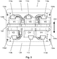
- the rear support 126 and the front support 128 hold three power and control distribution boxes 150. Each box 150 distributes power and control signals to a pair of cameras. For clarity, the power and control cabling between the boxes 150 and the cameras 110 and 112 is omitted in the figures.
- each detail camera 110 has a lens 114 with a focal length of 300mm suitable for high-resolution imaging at relatively high altitudes.
- a 300mm lens allows a ground sampling distance (GSD) of 10cm at 20,000 feet, 8cm at 16,000 feet, 6cm at 12,000 feet, 4cm at 8,000 feet, 2cm at 4,000 feet, and so on.
- the overview camera 112 ideally has a lens 116 with a focal length that is between 4 and 8 times shorter than the focal length of the detail lens 114, as discussed further below. I.e. for a 300mm detail lens 114, suitable focal lengths for the overview lens 116 range from about 40mm to 75mm. For illustrative purposes the present system utilises a 50mm overview lens 116.
- Fig. 6 shows the 6.90-degree lateral field of view 162 of each of the five detail cameras 110 with 300mm lenses 114, and the 39.60-degree lateral field of the overview camera 112 with a 50mm lens 116.
- the lateral direction is the direction perpendicular to the direction of flight 220
- the longitudinal direction is the direction parallel to the direction of flight 220.
- the detail cameras are angled 6 degrees apart laterally, i.e. slightly less than their 6.90-degree fields of view 162, so that the fields of view 162 overlap slightly.
- the five detail cameras 110 have an aggregate field of view with a pixel count of approximately 160Mpixels, i.e. excluding overlap.
- Stock telephoto lenses suitable for use as detail lenses 114 are available in a variety of focal lengths, typically including 85mm, 105mm, 135mm, 180mm, 200mm, 300mm, 400mm, 500mm, 600mm, 700mm, and 800mm.
- a 400mm lens on a Nikon D800 camera allows a GSD of 7.4cm, a 600mm lens a GSD of 5.0cm, and an 800mm lens a GSD of 3.7cm.
- Stock normal and wide-angle lenses suitable for use as an overview lens 116 are available in a variety of focal lengths, typically including 10.5mm, 14mm, 16mm, 18mm, 20mm, 21mm, 24mm, 28mm, 35mm, 40mm, 45mm, 50mm, 55mm, 60mm and 70mm.
- the camera unit 100 is readily adapted for different models and sizes of cameras 110 (and 112) and lenses 114 (and 116) via different camera mounts 140 (and 142) and clamps 144 (and 146). For extremely long lenses a taller center support 122 can be used.
- the detail cameras are angled inwards so that their fields of view 162 cross over directly below the camera unit 100, creating a waist of minimum diameter where the fields of view pass through the camera hole 212.
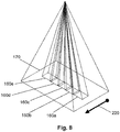
- Fig. 8 shows the projection of the three-dimensional fields of view 160 and 170 of the detail cameras 110 and overview camera 112 onto a ground plane. It shows how the detail field of views 160 overlap in a direction perpendicular to the direction of flight 220.
- Fig. 9 shows an adapter plate 200 that attaches to the seat tracks 214 of an aircraft, a Cessna 208 in this case, via standard seat track fasteners 202.
- the adapter plate has an aperture 216 which exposes a camera hole 212 through the floor 210 of the aircraft.
- Fig. 10 shows an exploded view of the camera unit 100, adapter plate 200, and the aircraft floor 210.
- the adapter plate 200 is designed to attach the camera unit 100 to a particular aircraft, and isolates the design of the camera unit 100 from aircraft specifics.
- a different adapter plate is designed for each aircraft attachment variation, e.g. due to different seat track spacings, or because the aircraft's camera hole installation includes its own mounting points.
- mount points 132 are bolted to the adapter plate, with each mount point 132 mating with a recess in the base of its corresponding mount point block 134.
- a mount bolt 143 securely attaches each mount point block 134 to its corresponding mount point 132, thus attaching the camera unit 100 to the adapter plate 200.
- the adapter plate 200 allows the camera unit 100 to be easily installed in and subsequently removed from an aircraft via installation and removal of the four mount bolts 143.
- the adapter plate 200 is itself generally easily installed in and removed from an aircraft, requiring no modification to the aircraft (assuming a suitable camera hole is already installed).
- the installation of external camera pod is generally a much more complicated operation.
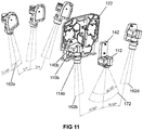
- Fig. 11 shows a variant of the camera unit 100 that utilises shorter 180mm lenses 114 for the detail cameras 110, and a matching 28mm lens 116 for the overview camera 112.
- a 180mm lens allows a ground sampling distance (GSD) of 9.9cm at 12,000 feet, 8.3cm at 10,000 feet, 6.6cm at 8,000 feet, 5cm at 6,000 feet, 3.3cm at 4,000 feet, and so on.
- GSD ground sampling distance
- Fig. 11 shows the 11.40-degree lateral field of view 162 of each of the five detail cameras 110 with 180mm lenses 114, and the 65.50-degree lateral field of the overview camera 112 with a 28mm lens 116.
- the detail cameras are angled 10.50 degrees apart laterally, i.e. slightly less than their 11.40-degree fields of view 162, so that the fields of view 162 overlap slightly.
- Fig. 12 shows the projection of the three-dimensional fields of view 160 and 170 of the detail cameras 110 and overview camera 112 of Fig. 10 onto a ground plane. It shows how the detail field of views 160 overlap in a direction perpendicular to the direction of flight 220, and how the wider fields of view associated with the shorter lenses leads to a lower operational altitude for the same footprint on the ground, i.e. in comparison to Fig. 8 .
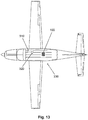
- Fig. 13 and Fig. 14 show plan views of a Cessna 208 survey aircraft 230 carrying a camera unit 100 installed centrally over a camera hole.
- the figures also show a camera control unit 310 (CCU) and battery unit 320 used to control and power the camera unit 100. These are described in more detail below. For clarity, the cabling connecting the CCU 310, battery unit 320 and camera unit 100 is omitted.
- Fig. 15 shows a front elevation of the Cessna 208 survey aircraft 230 carrying a HyperCamera, and shows the lateral overview field of view 172 of the camera unit 100, and the aggregate lateral detail field of view 182 of the camera unit 100.
- the aggregate lateral detail field of view 182 is the aggregate of the five individual overlapping lateral detail fields of view 162.
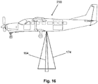
- Fig. 16 shows a side elevation of the Cessna 208 survey aircraft 230 carrying a HyperCamera, and shows the longitudinal overview field of view 174 of the camera unit 100, and the longitudinal detail field of view 164 of the camera unit 100.
- Fig. 17 shows the overlapping overview fields of view 170 and aggregate detail fields of view 180 of three successive shots in the direction of flight 220.
- the aggregate detail field of view 180 is the aggregate of the five individual overlapping detail fields of view 160.
- the aggregate detail fields of view 180 overlap by about 20% longitudinally, while the overview fields of view 170 overlap by about 85% longitudinally.
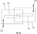
- Fig. 18 shows the overlapping overview fields of view 170 and aggregate detail fields of view 180 of two shots from adjacent flight lines, i.e. flown in opposite directions 220.
- the aggregate detail fields of view 180 overlap by between 20% and 25% laterally, while the overview fields of view 170 overlap by about 40% laterally.
- the size of the lateral overview field of view 172 and the size of the lateral aggregate detail field of view 182 are similar when the ratio of the focal length of the detail camera lens 114 to the focal length of the overview camera lens 116 is about 6, and useful lens combinations can be chosen with focal length ratios between about 4 and 8.
- Fig. 19 shows the overlapping aggregate detail fields of view 180 of a succession of shots along three adjacent flight lines that are part of a typical serpentine flight path 222, i.e. a subset of the flight lines that would make up a typical large-area survey. For clarity the corresponding overview fields of view 170 are omitted. The figure also shows the shot position 224 corresponding to each aggregate detail field of view 180, i.e. the position of the survey aircraft 230.
- the HyperCamera Compared with a traditional single-resolution aerial camera system and a comparable aggregate detail pixel count (e.g. 160Mpixel), the HyperCamera is between 2 and 3 times more efficient, as detailed below, with respect to both reduced survey flying time and fewer photos to process.
- the HyperCamera also has a higher efficiency than many aerial camera systems due to its high (detail) pixel count alone.
- the HyperCamera can be used to capture detail photos only, with higher overlap (e.g. 60/40 rather than 20/20), to allow the creation of a photomosaic with higher spatial accuracy, but at greater capture and processing cost.
- the overview camera 112 can be omitted.
- Fig. 20 shows a block diagram of a power and control system for the camera unit 100.
- the detail cameras 110 and overview camera 112 are controlled by a computer 300 via a set of analog-to-digital converters 308 (ADCs).
- ADCs analog-to-digital converters
- the computer 300 uses one or more Global Navigation Satellite System (GNSS) receiver 304 to monitor the position and speed of the survey aircraft 230 in real time.
- GNSS Global Navigation Satellite System
- the GNSS receiver(s) may be compatible with a variety of space-based satellite navigation systems, including the Global Positioning System (GPS), GLONASS, Galileo and BeiDou.
- GPS Global Positioning System
- GLONASS Global Positioning System
- Galileo Galileo
- BeiDou BeiDou.
- the computer 300 provides precisely-timed firing signals to the cameras 110 and 112 via the ADCs 308, to trigger camera exposure, according to a stored flight plan and the real-time position and speed of the aircraft. If a camera 110 and/or 112 incorporates an auto-focus mechanism then the computer 300 also provides a focus signal to each such camera to trigger auto-focus prior to exposure.
- the computer 300 fires the overview camera 112 and the detail cameras 110 at the same rate.
- the computer 300 may fire the overview camera 112 at a different rate to the detail cameras 110, i.e. either a higher rate or lower rate, to achieve a different overlap between successive overview photos, i.e. either a higher overlap or a lower overlap, independent of the overlap between successive detail photos.
- the computer 300 may fire the cameras simultaneously, or it may stagger the timing of the firing, e.g. to achieve a different alignment of photos longitudinally, or to reduce peak power consumption.
- the flight plan describes each flight line making up the survey, and the nominal camera firing rate along each flight line required to ensure that the necessary overlap is maintained between successive shots.
- the firing rate is sensitive to the elevation of the terrain below the aircraft, i.e. the higher the terrain the higher the firing rate needs to be. It is adjusted by the computer 300 according to the actual ground speed of the aircraft, which may vary from its nominal speed due to wind and the pilot's operation of the aircraft.
- the computer 300 also uses the flight plan and real-time GNSS position to guide the pilot along each flight line via a pilot display 302.
- the position data from the GNSS receiver is optionally augmented with orientation information from an inertial measurement unit 306 (IMU).
- IMU inertial measurement unit
- the computer stores the GNSS position (and optionally IMU orientation, if the IMU 306 is present) of each shot. This is used during subsequent processing of the photos to produce an accurate photomosaic.
- Each camera 110 and 112 stores its shots locally, e.g. in removable flash memory. This eliminates the need for centralised storage in the HyperCamera system, and the need for a high-bandwidth data communication channel between the cameras and the centralised storage.
- the GNSS position of each shot may be delivered to each camera 110 and 112, to allow the camera to tag each photo with its GNSS position.
- the cameras 110 and 112 are powered by a battery unit 320.
- the battery unit 320 provides a voltage higher than the voltage required by all connected components, e.g. between 24V and 28V, and the voltage requirement of each connected component is provided via a DC-DC converter 326.
- a Nikon D800 camera requires less than 10V.
- Additional DC-DC converters 326 also provide appropriate voltages to power the computer 300, the pilot display 302, the GNSS receiver 304, and the IMU 306. For clarity these power connections are omitted in Fig. 20 .
- the battery unit 320 contains two 12V or 14V batteries or a single 24V or 28V battery. It contains a charging circuit that allows it to be trickle-charged from an aircraft with a suitable auxiliary power source 322, allowing it to remain charged at all times. It may also be charged on the ground from a ground power unit 324 (GPU).
- GPU ground power unit
- the ADCs 308 and DC-DC converters 326 may be housed in a camera control unit 310 (CCU). This may additionally include a USB interface to allow the computer 300 to control the ADCs.
- CCU camera control unit
- the DC-DC converters 326 that provide power to the cameras 110 and 112 may be located in the CCU 310 or closer to the cameras in the distribution boxes 150.
- Fig. 21 shows a photogrammetric process flow for efficiently creating a photomosaic from multi-resolution HyperCamera photos. The process operates on detail photos 400 captured by the detail cameras 110, and overview photos 402 captured by the overview cameras 112.
- the process consists of four main steps: (1) features are automatically detected in each of the photos 400 and 402 and matched between photos (step 410); bundle adjustment is used to iteratively refine initial estimates of the real-world three-dimensional position of each feature, as well as the camera pose (three-dimensional position and orientation) and camera calibration (focal length and radial distortion) associated with each photo (at step 412); each detail photo 400 is orthorectified according to its camera pose and terrain elevation data (at step 414); and the orthorectified photos (orthophotos) are blended to form the final photomosaic 404 (at step 416).
- the accuracy of the photomosaic 404 derives from the high overlap between lower-resolution overview photos 402, while detail in the photomosaic 404 derives from the higher-resolution detail photos 400.
- a survey may be flown with higher overlap between the detail photos 400, and the photomosaic may be created from the detail photos 400 only.
- the photomosaic is typically stored as an image pyramid, i.e. within which different (binary) zoom levels are pre-computed for fast access at any zoom level.
- Lower zoom levels in the pyramid are generated from higher zoom levels by low-pass filtering and subsampling, thus the entire pyramid may be generated from the detail-resolution photomosaic.
- lower zoom levels may be generated from a photomosaic created from the overview photos 402, in which case the overview photos 402 are also orthorectified and blended as described above for the detail photos 400.
- An initial estimate of the camera pose of each photo, subsequently refined by the bundle adjustment process (at step 412), is derived from the GNSS position of each photo, as well as its IMU-derived orientation, if available.
- the terrain data used to orthorectify (at step 414) the detail photos 400 may be based on 3D feature positions obtained from bundle adjustment (at step 412), or may be terrain data sourced from elsewhere (such as from a LiDAR aerial survey).
- Automatically detected ground features may be augmented with manually-identified ground points, each of which may have an accurate surveyed real-world position (and is then referred to as a ground control point),
Claims (18)
- System zum Erfassen von Luftbildern, wobei das System ein Flugzeug (230) und mindestens eine Übersichtskamera (112) aufweist und es gekennzeichnet ist durch:(a) eine Vielzahl an Detailkameras (110) und einen Rahmen zum Halten der Kameras, wobei jede Detailkamera (110) eine längere Brennweite als die mindestens eine Übersichtskamera (112) aufweist,(b) wobei die Detailkameras (110) auf eine solche Weise angebracht sind, dass ihre Sichtfelder (160) sich ungeachtet einer Bewegung des Flugzeugs (230) teilweise überlappen, um ein Gesamtblickfeld zu bilden, das in der Richtung im Wesentlichen horizontal und senkrecht zur Flugrichtung (220) des Flugzeugs (230) verlängert ist,(c) wobei der Rahmen an dem Boden (210) des Flugzeugs (230) über einer Kameraöffnung (212) angebracht werden kann, wodurch die Kameras (110, 112) mit einer Sicht auf den Boden unter dem Flugzeug (230) durch die Kameraöffnung (212) versehen werden, und(d) die Detailkameras (110) auf eine solche Weise angebracht sind, dass ihre Sichtfelder (160) nahe und unter den Detailkameras (110) konvergieren und sich kreuzen, wodurch eine Einschnürung in dem Gesamtblickfeld (160) ausreichend klein gemacht wird, um zu ermöglichen, dass die Sichtfelder (160) ungehindert durch das Kameraloch (212) hindurchgehen können.
- System nach Anspruch 1, welches ferner eine Adapterplatte (200) aufweist, die an dem Boden (210) des Flugzeugs (230) angebracht werden kann, wobei der Rahmen an der Adapterplatte (200) befestigt werden kann.
- System nach Anspruch 2, bei dem die Adapterplatte (200) an dem Boden (210) durch ein Verschrauben an Montagepunkten angebracht ist, die in den Boden (210) eingesetzt sind.
- System nach Anspruch 2, bei dem die Adapterplatte (200) an dem Boden (210) durch ein Verschrauben mit Sitzschienen (214) angebracht ist, die an dem Boden (210) befestigt sind.
- System nach einem der Ansprüche 1 bis 4, wobei die Verhältnisse der Brennweiten der Detailkameras (110) zu der Brennweite der mindestens einen Übersichtskamera (112) zwischen 4 und 8 liegen.
- System nach einem der Ansprüche 1 bis 5, bei dem die Brennweiten der Detailkameras (110) zwischen 85 mm und 800 mm liegen.
- System nach einem der Ansprüche 1 bis 5, bei dem die Brennweiten der Detailkameras (110) aus der Gruppe ausgewählt worden sind, die 85 mm, 105 mm, 135 mm, 180 mm, 200 mm, 300 mm, 400 mm, 500 mm, 600 mm, 700 mm und 800 mm umfasst.
- System nach einem der Ansprüche 1 bis 7, bei dem die Brennweite der wenigstens einen Übersichtskamera (112) zwischen 10 mm und 200 mm beträgt.
- System nach einem der Ansprüche 1 bis 7, bei dem die Brennweite der mindestens einen Übersichtskamera (112) aus der Gruppe ausgewählt worden ist, die 10,5 mm, 14 mm, 16 mm, 18 mm, 20 mm, 21 mm, 24 mm, 28 mm, 35 mm, 40 mm, 45 mm, 50 mm, 55 mm und 60 mm umfasst.
- System nach einem der Ansprüche 1 bis 9, bei dem fünf Detailkameras (110) vorhanden sind.
- System nach einem der Ansprüche 1 bis 10, bei dem die Detailkameras (110) Linsen (114) mit einem festen Fokus aufweisen, die auf Unendlich fokussiert sind.
- System nach einem der Ansprüche 1 bis 10, bei dem die Detailkameras (110) Linsen (114) mit variablem Brennpunkt und Autofokusmechanismen aufweisen.
- System nach einem der Ansprüche 1 bis 12, bei dem die mindestens eine Übersichtskamera (112) eine Linse (116) mit einem festen Fokus aufweist, die auf Unendlich fokussiert ist.
- System nach einem der Ansprüche 1 bis 12, bei dem die mindestens eine Übersichtskamera (112) eine Linse (116) mit einem variablen Brennpunkt und einen Autofokusmechanismus aufweist.
- System nach einem der Ansprüche 1 bis 14, das ferner ein Computersystem (300) umfasst, das ausgestaltet ist, um die Detailkameras (110) während des Flugs automatisch auszulösen, so dass aufeinanderfolgende Detailfotos sich in Längsrichtung überlappen.
- System nach Anspruch 15, das ferner mindestens einen GNSS-Empfänger (304) aufweist, wobei der Computer (300) ausgestaltet ist, Positionsdaten von dem mindestens einen GNSS-Empfänger (304) in Echtzeit zu empfangen und zu speichern.
- System nach Anspruch 16, das ferner eine Trägheitsmesseinheit (306) aufweist, wobei der Computer (300) ausgestaltet ist, um Ausrichtungsdaten von der Trägheitsmesseinheit (306) in Echtzeit zu empfangen und zu speichern.
- System nach einem der Ansprüche 15 bis 17, das ferner einen gespeicherten Flugplan aufweist, wobei der Computer (300) ausgestaltet ist, um die Kameras (110, 112) mit einer aus dem Flugplan ermittelten Rate der Echtzeit-Position des Flugzeuges (230) und der Echtzeitgeschwindigkeit des Flugzeugs (230) auszulösen.
Applications Claiming Priority (2)
| Application Number | Priority Date | Filing Date | Title |
|---|---|---|---|
| US14/310,523 US9046759B1 (en) | 2014-06-20 | 2014-06-20 | Compact multi-resolution aerial camera system |
| PCT/AU2014/050401 WO2015192163A1 (en) | 2014-06-20 | 2014-12-08 | High-altitude aerial camera systems |
Publications (3)
| Publication Number | Publication Date |
|---|---|
| EP3158290A1 EP3158290A1 (de) | 2017-04-26 |
| EP3158290A4 EP3158290A4 (de) | 2017-12-13 |
| EP3158290B1 true EP3158290B1 (de) | 2019-01-30 |
Family
ID=53190618
Family Applications (1)
| Application Number | Title | Priority Date | Filing Date |
|---|---|---|---|
| EP14894991.0A Active EP3158290B1 (de) | 2014-06-20 | 2014-12-08 | Luftbildkamerasysteme für grosse höhen |
Country Status (8)
| Country | Link |
|---|---|
| US (2) | US9046759B1 (de) |
| EP (1) | EP3158290B1 (de) |
| JP (1) | JP6339245B2 (de) |
| CN (1) | CN106574835B (de) |
| AU (1) | AU2014274497B2 (de) |
| CA (1) | CA2952866C (de) |
| ES (1) | ES2720751T3 (de) |
| WO (1) | WO2015192163A1 (de) |
Families Citing this family (21)
| Publication number | Priority date | Publication date | Assignee | Title |
|---|---|---|---|---|
| US9641736B2 (en) | 2014-06-20 | 2017-05-02 | nearmap australia pty ltd. | Wide-area aerial camera systems |
| US9185290B1 (en) * | 2014-06-20 | 2015-11-10 | Nearmap Australia Pty Ltd | Wide-area aerial camera systems |
| US9052571B1 (en) * | 2014-06-20 | 2015-06-09 | nearmap australia pty ltd. | Wide-area aerial camera systems |
| US9046759B1 (en) * | 2014-06-20 | 2015-06-02 | nearmap australia pty ltd. | Compact multi-resolution aerial camera system |
| US9440750B2 (en) * | 2014-06-20 | 2016-09-13 | nearmap australia pty ltd. | Wide-area aerial camera systems |
| WO2016054681A1 (en) | 2014-10-08 | 2016-04-14 | Spookfish Innovations Pty Ltd | An aerial camera system |
| FR3038482B1 (fr) * | 2015-06-30 | 2017-08-11 | Parrot | Bloc camera apte a etre embarque dans un drone pour cartographier un terrain et procede de gestion de capture d'images par un bloc camera |
| US9945828B1 (en) | 2015-10-23 | 2018-04-17 | Sentek Systems Llc | Airborne multispectral imaging system with integrated navigation sensors and automatic image stitching |
| IL242790B (en) | 2015-11-26 | 2018-11-29 | Israel Aerospace Ind Ltd | Aerial photography system |
| CN109076173A (zh) * | 2017-11-21 | 2018-12-21 | 深圳市大疆创新科技有限公司 | 输出影像生成方法、设备及无人机 |
| CN107867407A (zh) * | 2017-11-24 | 2018-04-03 | 杭州时光坐标影视传媒股份有限公司 | 一种自稳定的航拍全景拍摄云台 |
| CN108313317A (zh) * | 2018-01-26 | 2018-07-24 | 广州市红鹏直升机遥感科技有限公司 | 一种拼接式高速航空摄影云台 |
| CN108528743A (zh) * | 2018-06-04 | 2018-09-14 | 济南赛尔无人机科技有限公司 | 一种可调角度的无人机照相装置及照相方法 |
| CN108846084B (zh) * | 2018-06-11 | 2021-06-29 | 成都山河空间信息技术有限公司 | 一种实景地图的生成系统和方法 |
| WO2020065719A1 (ja) * | 2018-09-25 | 2020-04-02 | 株式会社エアロネクスト | 飛行体 |
| JP7220785B2 (ja) * | 2018-11-21 | 2023-02-10 | 広州極飛科技股▲ふん▼有限公司 | 測量用サンプリング点の計画方法、装置、制御端末及び記憶媒体 |
| US20200210676A1 (en) * | 2018-12-27 | 2020-07-02 | Simplex Mapping Solutions Sb Ltd. | Compact interval sweeping imaging system and method |
| JP6681105B2 (ja) * | 2019-11-28 | 2020-04-15 | 株式会社エアロネクスト | 飛行体 |
| CN112470071B (zh) * | 2020-02-28 | 2021-12-21 | 深圳市大疆创新科技有限公司 | 三光相机、云台结构及移动平台 |
| CN111595301B (zh) * | 2020-05-20 | 2021-11-23 | 福建省伟志地理信息科学研究院 | 一种地理信息系统用航空测量装置及其测量方法 |
| US20220417396A1 (en) | 2021-06-28 | 2022-12-29 | nearmap australia pty ltd. | Hyper camera with shared mirror |
Family Cites Families (18)
| Publication number | Priority date | Publication date | Assignee | Title |
|---|---|---|---|---|
| US1797849A (en) * | 1926-12-16 | 1931-03-24 | Firm Photogrammetrie G M B H | Multiple chamber for taking photographs from aeroplanes |
| US1735109A (en) * | 1927-02-08 | 1929-11-12 | Leon T Eliel | Process of and apparatus for making aerial photographs |
| GB671674A (en) * | 1949-04-26 | 1952-05-07 | Stuart Williamson | Improvements in mountings for aerial survey cameras |
| US2665481A (en) * | 1951-03-02 | 1954-01-12 | James E Henry | Method of aerial mapping |
| FR2696843B1 (fr) * | 1992-10-14 | 1994-12-09 | Matra Sep Imagerie Inf | Appareil de prise de vues à distance, à haute résolution, pour porteur aérien. |
| US5894323A (en) * | 1996-03-22 | 1999-04-13 | Tasc, Inc, | Airborne imaging system using global positioning system (GPS) and inertial measurement unit (IMU) data |
| DE10034601B4 (de) * | 2000-07-14 | 2013-05-23 | Leica Geosystems Ag | Kamerasystem mit mindestens zwei ersten und zweiten Kameras |
| US20070188610A1 (en) * | 2006-02-13 | 2007-08-16 | The Boeing Company | Synoptic broad-area remote-sensing via multiple telescopes |
| US8581981B2 (en) * | 2006-04-28 | 2013-11-12 | Southwest Research Institute | Optical imaging system for unmanned aerial vehicle |
| US9262818B2 (en) * | 2007-05-01 | 2016-02-16 | Pictometry International Corp. | System for detecting image abnormalities |
| US8675068B2 (en) * | 2008-04-11 | 2014-03-18 | Nearmap Australia Pty Ltd | Systems and methods of capturing large area images in detail including cascaded cameras and/or calibration features |
| US8497905B2 (en) * | 2008-04-11 | 2013-07-30 | nearmap australia pty ltd. | Systems and methods of capturing large area images in detail including cascaded cameras and/or calibration features |
| US7899311B1 (en) * | 2008-04-29 | 2011-03-01 | Optech International, Inc. | Removable shutter for a camera |
| IL201682A0 (en) * | 2009-10-22 | 2010-11-30 | Bluebird Aero Systems Ltd | Imaging system for uav |
| US8687062B1 (en) * | 2011-08-31 | 2014-04-01 | Google Inc. | Step-stare oblique aerial camera system |
| US8559802B1 (en) * | 2012-05-25 | 2013-10-15 | Google Inc. | System and method for isolating camera movement |
| US9052571B1 (en) * | 2014-06-20 | 2015-06-09 | nearmap australia pty ltd. | Wide-area aerial camera systems |
| US9046759B1 (en) * | 2014-06-20 | 2015-06-02 | nearmap australia pty ltd. | Compact multi-resolution aerial camera system |
-
2014
- 2014-06-20 US US14/310,523 patent/US9046759B1/en active Active
- 2014-12-08 ES ES14894991T patent/ES2720751T3/es active Active
- 2014-12-08 CN CN201480080029.3A patent/CN106574835B/zh active Active
- 2014-12-08 AU AU2014274497A patent/AU2014274497B2/en active Active
- 2014-12-08 CA CA2952866A patent/CA2952866C/en active Active
- 2014-12-08 WO PCT/AU2014/050401 patent/WO2015192163A1/en active Application Filing
- 2014-12-08 JP JP2016576098A patent/JP6339245B2/ja active Active
- 2014-12-08 EP EP14894991.0A patent/EP3158290B1/de active Active
-
2015
- 2015-05-21 US US14/718,472 patent/US9188838B1/en active Active
Non-Patent Citations (1)
| Title |
|---|
| None * |
Also Published As
| Publication number | Publication date |
|---|---|
| EP3158290A1 (de) | 2017-04-26 |
| CN106574835B (zh) | 2018-03-23 |
| CN106574835A (zh) | 2017-04-19 |
| JP2017521658A (ja) | 2017-08-03 |
| ES2720751T3 (es) | 2019-07-24 |
| WO2015192163A1 (en) | 2015-12-23 |
| AU2014274497B2 (en) | 2017-03-02 |
| JP6339245B2 (ja) | 2018-06-06 |
| CA2952866A1 (en) | 2015-12-23 |
| CA2952866C (en) | 2018-03-06 |
| EP3158290A4 (de) | 2017-12-13 |
| CN106574835A8 (zh) | 2017-06-16 |
| AU2014274497A1 (en) | 2016-01-21 |
| US9046759B1 (en) | 2015-06-02 |
| US9188838B1 (en) | 2015-11-17 |
Similar Documents
| Publication | Publication Date | Title |
|---|---|---|
| EP3158290B1 (de) | Luftbildkamerasysteme für grosse höhen | |
| EP3158291B1 (de) | Luftbildkamerasysteme mit grosser abdeckung | |
| EP3158396B1 (de) | Luftbildkamerasysteme mit grosser abdeckung | |
| US9440750B2 (en) | Wide-area aerial camera systems | |
| US9641736B2 (en) | Wide-area aerial camera systems | |
| RU2562707C2 (ru) | Системы и способы захвата изображений большой площади по частям, включающие в себя каскадные камеры и/или калибровочные признаки | |
| CA2975758C (en) | Corridor capture |
Legal Events
| Date | Code | Title | Description |
|---|---|---|---|
| STAA | Information on the status of an ep patent application or granted ep patent |
Free format text: STATUS: THE INTERNATIONAL PUBLICATION HAS BEEN MADE |
|
| PUAI | Public reference made under article 153(3) epc to a published international application that has entered the european phase |
Free format text: ORIGINAL CODE: 0009012 |
|
| STAA | Information on the status of an ep patent application or granted ep patent |
Free format text: STATUS: REQUEST FOR EXAMINATION WAS MADE |
|
| 17P | Request for examination filed |
Effective date: 20161220 |
|
| AK | Designated contracting states |
Kind code of ref document: A1 Designated state(s): AL AT BE BG CH CY CZ DE DK EE ES FI FR GB GR HR HU IE IS IT LI LT LU LV MC MK MT NL NO PL PT RO RS SE SI SK SM TR |
|
| AX | Request for extension of the european patent |
Extension state: BA ME |
|
| DAX | Request for extension of the european patent (deleted) | ||
| REG | Reference to a national code |
Ref country code: DE Ref legal event code: R079 Ref document number: 602014040630 Country of ref document: DE Free format text: PREVIOUS MAIN CLASS: G01C0011020000 Ipc: G03B0037000000 |
|
| A4 | Supplementary search report drawn up and despatched |
Effective date: 20171115 |
|
| RIC1 | Information provided on ipc code assigned before grant |
Ipc: B64D 47/08 20060101ALI20171109BHEP Ipc: G03B 37/00 20060101AFI20171109BHEP Ipc: G03B 37/04 20060101ALI20171109BHEP Ipc: G01C 11/02 20060101ALI20171109BHEP |
|
| RAP1 | Party data changed (applicant data changed or rights of an application transferred) |
Owner name: NEARMAP AUSTRALIA PTY LTD |
|
| GRAP | Despatch of communication of intention to grant a patent |
Free format text: ORIGINAL CODE: EPIDOSNIGR1 |
|
| STAA | Information on the status of an ep patent application or granted ep patent |
Free format text: STATUS: GRANT OF PATENT IS INTENDED |
|
| INTG | Intention to grant announced |
Effective date: 20180801 |
|
| GRAS | Grant fee paid |
Free format text: ORIGINAL CODE: EPIDOSNIGR3 |
|
| RAP1 | Party data changed (applicant data changed or rights of an application transferred) |
Owner name: NEARMAP AUSTRALIA PTY LTD |
|
| GRAA | (expected) grant |
Free format text: ORIGINAL CODE: 0009210 |
|
| STAA | Information on the status of an ep patent application or granted ep patent |
Free format text: STATUS: THE PATENT HAS BEEN GRANTED |
|
| AK | Designated contracting states |
Kind code of ref document: B1 Designated state(s): AL AT BE BG CH CY CZ DE DK EE ES FI FR GB GR HR HU IE IS IT LI LT LU LV MC MK MT NL NO PL PT RO RS SE SI SK SM TR |
|
| REG | Reference to a national code |
Ref country code: GB Ref legal event code: FG4D |
|
| REG | Reference to a national code |
Ref country code: CH Ref legal event code: EP |
|
| REG | Reference to a national code |
Ref country code: AT Ref legal event code: REF Ref document number: 1093736 Country of ref document: AT Kind code of ref document: T Effective date: 20190215 |
|
| REG | Reference to a national code |
Ref country code: IE Ref legal event code: FG4D |
|
| REG | Reference to a national code |
Ref country code: DE Ref legal event code: R096 Ref document number: 602014040630 Country of ref document: DE |
|
| REG | Reference to a national code |
Ref country code: NL Ref legal event code: FP |
|
| REG | Reference to a national code |
Ref country code: LT Ref legal event code: MG4D |
|
| REG | Reference to a national code |
Ref country code: ES Ref legal event code: FG2A Ref document number: 2720751 Country of ref document: ES Kind code of ref document: T3 Effective date: 20190724 |
|
| PG25 | Lapsed in a contracting state [announced via postgrant information from national office to epo] |
Ref country code: SE Free format text: LAPSE BECAUSE OF FAILURE TO SUBMIT A TRANSLATION OF THE DESCRIPTION OR TO PAY THE FEE WITHIN THE PRESCRIBED TIME-LIMIT Effective date: 20190130 Ref country code: PL Free format text: LAPSE BECAUSE OF FAILURE TO SUBMIT A TRANSLATION OF THE DESCRIPTION OR TO PAY THE FEE WITHIN THE PRESCRIBED TIME-LIMIT Effective date: 20190130 Ref country code: LT Free format text: LAPSE BECAUSE OF FAILURE TO SUBMIT A TRANSLATION OF THE DESCRIPTION OR TO PAY THE FEE WITHIN THE PRESCRIBED TIME-LIMIT Effective date: 20190130 Ref country code: FI Free format text: LAPSE BECAUSE OF FAILURE TO SUBMIT A TRANSLATION OF THE DESCRIPTION OR TO PAY THE FEE WITHIN THE PRESCRIBED TIME-LIMIT Effective date: 20190130 Ref country code: PT Free format text: LAPSE BECAUSE OF FAILURE TO SUBMIT A TRANSLATION OF THE DESCRIPTION OR TO PAY THE FEE WITHIN THE PRESCRIBED TIME-LIMIT Effective date: 20190530 Ref country code: NO Free format text: LAPSE BECAUSE OF FAILURE TO SUBMIT A TRANSLATION OF THE DESCRIPTION OR TO PAY THE FEE WITHIN THE PRESCRIBED TIME-LIMIT Effective date: 20190430 |
|
| REG | Reference to a national code |
Ref country code: AT Ref legal event code: MK05 Ref document number: 1093736 Country of ref document: AT Kind code of ref document: T Effective date: 20190130 |
|
| PG25 | Lapsed in a contracting state [announced via postgrant information from national office to epo] |
Ref country code: BG Free format text: LAPSE BECAUSE OF FAILURE TO SUBMIT A TRANSLATION OF THE DESCRIPTION OR TO PAY THE FEE WITHIN THE PRESCRIBED TIME-LIMIT Effective date: 20190430 Ref country code: LV Free format text: LAPSE BECAUSE OF FAILURE TO SUBMIT A TRANSLATION OF THE DESCRIPTION OR TO PAY THE FEE WITHIN THE PRESCRIBED TIME-LIMIT Effective date: 20190130 Ref country code: IS Free format text: LAPSE BECAUSE OF FAILURE TO SUBMIT A TRANSLATION OF THE DESCRIPTION OR TO PAY THE FEE WITHIN THE PRESCRIBED TIME-LIMIT Effective date: 20190530 Ref country code: HR Free format text: LAPSE BECAUSE OF FAILURE TO SUBMIT A TRANSLATION OF THE DESCRIPTION OR TO PAY THE FEE WITHIN THE PRESCRIBED TIME-LIMIT Effective date: 20190130 Ref country code: RS Free format text: LAPSE BECAUSE OF FAILURE TO SUBMIT A TRANSLATION OF THE DESCRIPTION OR TO PAY THE FEE WITHIN THE PRESCRIBED TIME-LIMIT Effective date: 20190130 Ref country code: GR Free format text: LAPSE BECAUSE OF FAILURE TO SUBMIT A TRANSLATION OF THE DESCRIPTION OR TO PAY THE FEE WITHIN THE PRESCRIBED TIME-LIMIT Effective date: 20190501 |
|
| PG25 | Lapsed in a contracting state [announced via postgrant information from national office to epo] |
Ref country code: AL Free format text: LAPSE BECAUSE OF FAILURE TO SUBMIT A TRANSLATION OF THE DESCRIPTION OR TO PAY THE FEE WITHIN THE PRESCRIBED TIME-LIMIT Effective date: 20190130 Ref country code: CZ Free format text: LAPSE BECAUSE OF FAILURE TO SUBMIT A TRANSLATION OF THE DESCRIPTION OR TO PAY THE FEE WITHIN THE PRESCRIBED TIME-LIMIT Effective date: 20190130 Ref country code: RO Free format text: LAPSE BECAUSE OF FAILURE TO SUBMIT A TRANSLATION OF THE DESCRIPTION OR TO PAY THE FEE WITHIN THE PRESCRIBED TIME-LIMIT Effective date: 20190130 Ref country code: SK Free format text: LAPSE BECAUSE OF FAILURE TO SUBMIT A TRANSLATION OF THE DESCRIPTION OR TO PAY THE FEE WITHIN THE PRESCRIBED TIME-LIMIT Effective date: 20190130 Ref country code: EE Free format text: LAPSE BECAUSE OF FAILURE TO SUBMIT A TRANSLATION OF THE DESCRIPTION OR TO PAY THE FEE WITHIN THE PRESCRIBED TIME-LIMIT Effective date: 20190130 Ref country code: DK Free format text: LAPSE BECAUSE OF FAILURE TO SUBMIT A TRANSLATION OF THE DESCRIPTION OR TO PAY THE FEE WITHIN THE PRESCRIBED TIME-LIMIT Effective date: 20190130 |
|
| REG | Reference to a national code |
Ref country code: DE Ref legal event code: R097 Ref document number: 602014040630 Country of ref document: DE |
|
| PG25 | Lapsed in a contracting state [announced via postgrant information from national office to epo] |
Ref country code: SM Free format text: LAPSE BECAUSE OF FAILURE TO SUBMIT A TRANSLATION OF THE DESCRIPTION OR TO PAY THE FEE WITHIN THE PRESCRIBED TIME-LIMIT Effective date: 20190130 |
|
| PLBE | No opposition filed within time limit |
Free format text: ORIGINAL CODE: 0009261 |
|
| STAA | Information on the status of an ep patent application or granted ep patent |
Free format text: STATUS: NO OPPOSITION FILED WITHIN TIME LIMIT |
|
| PG25 | Lapsed in a contracting state [announced via postgrant information from national office to epo] |
Ref country code: AT Free format text: LAPSE BECAUSE OF FAILURE TO SUBMIT A TRANSLATION OF THE DESCRIPTION OR TO PAY THE FEE WITHIN THE PRESCRIBED TIME-LIMIT Effective date: 20190130 |
|
| 26N | No opposition filed |
Effective date: 20191031 |
|
| PG25 | Lapsed in a contracting state [announced via postgrant information from national office to epo] |
Ref country code: SI Free format text: LAPSE BECAUSE OF FAILURE TO SUBMIT A TRANSLATION OF THE DESCRIPTION OR TO PAY THE FEE WITHIN THE PRESCRIBED TIME-LIMIT Effective date: 20190130 |
|
| PG25 | Lapsed in a contracting state [announced via postgrant information from national office to epo] |
Ref country code: TR Free format text: LAPSE BECAUSE OF FAILURE TO SUBMIT A TRANSLATION OF THE DESCRIPTION OR TO PAY THE FEE WITHIN THE PRESCRIBED TIME-LIMIT Effective date: 20190130 |
|
| REG | Reference to a national code |
Ref country code: CH Ref legal event code: PL |
|
| REG | Reference to a national code |
Ref country code: BE Ref legal event code: MM Effective date: 20191231 |
|
| PG25 | Lapsed in a contracting state [announced via postgrant information from national office to epo] |
Ref country code: MC Free format text: LAPSE BECAUSE OF FAILURE TO SUBMIT A TRANSLATION OF THE DESCRIPTION OR TO PAY THE FEE WITHIN THE PRESCRIBED TIME-LIMIT Effective date: 20190130 |
|
| PG25 | Lapsed in a contracting state [announced via postgrant information from national office to epo] |
Ref country code: IE Free format text: LAPSE BECAUSE OF NON-PAYMENT OF DUE FEES Effective date: 20191208 Ref country code: LU Free format text: LAPSE BECAUSE OF NON-PAYMENT OF DUE FEES Effective date: 20191208 |
|
| PG25 | Lapsed in a contracting state [announced via postgrant information from national office to epo] |
Ref country code: LI Free format text: LAPSE BECAUSE OF NON-PAYMENT OF DUE FEES Effective date: 20191231 Ref country code: BE Free format text: LAPSE BECAUSE OF NON-PAYMENT OF DUE FEES Effective date: 20191231 Ref country code: CH Free format text: LAPSE BECAUSE OF NON-PAYMENT OF DUE FEES Effective date: 20191231 |
|
| PG25 | Lapsed in a contracting state [announced via postgrant information from national office to epo] |
Ref country code: CY Free format text: LAPSE BECAUSE OF FAILURE TO SUBMIT A TRANSLATION OF THE DESCRIPTION OR TO PAY THE FEE WITHIN THE PRESCRIBED TIME-LIMIT Effective date: 20190130 |
|
| PG25 | Lapsed in a contracting state [announced via postgrant information from national office to epo] |
Ref country code: MT Free format text: LAPSE BECAUSE OF FAILURE TO SUBMIT A TRANSLATION OF THE DESCRIPTION OR TO PAY THE FEE WITHIN THE PRESCRIBED TIME-LIMIT Effective date: 20190130 Ref country code: HU Free format text: LAPSE BECAUSE OF FAILURE TO SUBMIT A TRANSLATION OF THE DESCRIPTION OR TO PAY THE FEE WITHIN THE PRESCRIBED TIME-LIMIT; INVALID AB INITIO Effective date: 20141208 |
|
| PG25 | Lapsed in a contracting state [announced via postgrant information from national office to epo] |
Ref country code: MK Free format text: LAPSE BECAUSE OF FAILURE TO SUBMIT A TRANSLATION OF THE DESCRIPTION OR TO PAY THE FEE WITHIN THE PRESCRIBED TIME-LIMIT Effective date: 20190130 |
|
| PGFP | Annual fee paid to national office [announced via postgrant information from national office to epo] |
Ref country code: ES Payment date: 20230112 Year of fee payment: 9 |
|
| P01 | Opt-out of the competence of the unified patent court (upc) registered |
Effective date: 20230515 |
|
| PGFP | Annual fee paid to national office [announced via postgrant information from national office to epo] |
Ref country code: NL Payment date: 20231116 Year of fee payment: 10 |
|
| PGFP | Annual fee paid to national office [announced via postgrant information from national office to epo] |
Ref country code: GB Payment date: 20231102 Year of fee payment: 10 |
|
| PGFP | Annual fee paid to national office [announced via postgrant information from national office to epo] |
Ref country code: IT Payment date: 20231110 Year of fee payment: 10 Ref country code: FR Payment date: 20231108 Year of fee payment: 10 Ref country code: DE Payment date: 20231031 Year of fee payment: 10 |
|
| PGFP | Annual fee paid to national office [announced via postgrant information from national office to epo] |
Ref country code: ES Payment date: 20240118 Year of fee payment: 10 |