EP3157686B1 - Methods and apparatus for applying protective films - Google Patents
Methods and apparatus for applying protective films Download PDFInfo
- Publication number
- EP3157686B1 EP3157686B1 EP15734513.3A EP15734513A EP3157686B1 EP 3157686 B1 EP3157686 B1 EP 3157686B1 EP 15734513 A EP15734513 A EP 15734513A EP 3157686 B1 EP3157686 B1 EP 3157686B1
- Authority
- EP
- European Patent Office
- Prior art keywords
- die
- ribbon
- film
- applicator
- spacer
- Prior art date
- Legal status (The legal status is an assumption and is not a legal conclusion. Google has not performed a legal analysis and makes no representation as to the accuracy of the status listed.)
- Active
Links
- 238000000034 method Methods 0.000 title claims description 32
- 230000001681 protective effect Effects 0.000 title claims description 9
- 239000000463 material Substances 0.000 claims description 57
- 239000000839 emulsion Substances 0.000 claims description 15
- 125000006850 spacer group Chemical group 0.000 claims description 15
- 238000000576 coating method Methods 0.000 claims description 13
- 239000011248 coating agent Substances 0.000 claims description 12
- 229920000642 polymer Polymers 0.000 claims description 9
- 239000011118 polyvinyl acetate Substances 0.000 claims description 8
- 238000001125 extrusion Methods 0.000 claims description 6
- 238000004519 manufacturing process Methods 0.000 claims description 6
- 229920002689 polyvinyl acetate Polymers 0.000 claims description 6
- 238000001035 drying Methods 0.000 claims description 5
- 239000003973 paint Substances 0.000 claims description 5
- 230000005855 radiation Effects 0.000 claims description 3
- 238000010438 heat treatment Methods 0.000 claims 1
- 239000010408 film Substances 0.000 description 28
- 239000004800 polyvinyl chloride Substances 0.000 description 9
- 229920000915 polyvinyl chloride Polymers 0.000 description 8
- 238000010586 diagram Methods 0.000 description 6
- 238000005507 spraying Methods 0.000 description 5
- 230000000873 masking effect Effects 0.000 description 4
- XLYOFNOQVPJJNP-UHFFFAOYSA-N water Substances O XLYOFNOQVPJJNP-UHFFFAOYSA-N 0.000 description 4
- 238000004140 cleaning Methods 0.000 description 3
- 239000012530 fluid Substances 0.000 description 3
- 239000002904 solvent Substances 0.000 description 3
- 239000007921 spray Substances 0.000 description 3
- 239000007864 aqueous solution Substances 0.000 description 2
- 238000000889 atomisation Methods 0.000 description 2
- 239000003599 detergent Substances 0.000 description 2
- 239000007788 liquid Substances 0.000 description 2
- 239000002985 plastic film Substances 0.000 description 2
- 229920006255 plastic film Polymers 0.000 description 2
- 239000011253 protective coating Substances 0.000 description 2
- 238000003860 storage Methods 0.000 description 2
- 229910001369 Brass Inorganic materials 0.000 description 1
- 244000208734 Pisonia aculeata Species 0.000 description 1
- 238000010420 art technique Methods 0.000 description 1
- 239000010951 brass Substances 0.000 description 1
- 239000002826 coolant Substances 0.000 description 1
- 230000001627 detrimental effect Effects 0.000 description 1
- 238000010030 laminating Methods 0.000 description 1
- 239000002184 metal Substances 0.000 description 1
- 239000003960 organic solvent Substances 0.000 description 1
- 238000010422 painting Methods 0.000 description 1
- 239000002245 particle Substances 0.000 description 1
- 229920003023 plastic Polymers 0.000 description 1
- 239000004033 plastic Substances 0.000 description 1
- 238000009417 prefabrication Methods 0.000 description 1
- 239000003380 propellant Substances 0.000 description 1
- 239000011241 protective layer Substances 0.000 description 1
- 238000010926 purge Methods 0.000 description 1
- 239000007787 solid Substances 0.000 description 1
- 239000000243 solution Substances 0.000 description 1
- 229910001220 stainless steel Inorganic materials 0.000 description 1
- 239000010935 stainless steel Substances 0.000 description 1
- 239000010409 thin film Substances 0.000 description 1
- 239000013585 weight reducing agent Substances 0.000 description 1
Images


Classifications
-
- B—PERFORMING OPERATIONS; TRANSPORTING
- B32—LAYERED PRODUCTS
- B32B—LAYERED PRODUCTS, i.e. PRODUCTS BUILT-UP OF STRATA OF FLAT OR NON-FLAT, e.g. CELLULAR OR HONEYCOMB, FORM
- B32B37/00—Methods or apparatus for laminating, e.g. by curing or by ultrasonic bonding
- B32B37/14—Methods or apparatus for laminating, e.g. by curing or by ultrasonic bonding characterised by the properties of the layers
- B32B37/15—Methods or apparatus for laminating, e.g. by curing or by ultrasonic bonding characterised by the properties of the layers with at least one layer being manufactured and immediately laminated before reaching its stable state, e.g. in which a layer is extruded and laminated while in semi-molten state
- B32B37/153—Methods or apparatus for laminating, e.g. by curing or by ultrasonic bonding characterised by the properties of the layers with at least one layer being manufactured and immediately laminated before reaching its stable state, e.g. in which a layer is extruded and laminated while in semi-molten state at least one layer is extruded and immediately laminated while in semi-molten state
-
- B—PERFORMING OPERATIONS; TRANSPORTING
- B05—SPRAYING OR ATOMISING IN GENERAL; APPLYING FLUENT MATERIALS TO SURFACES, IN GENERAL
- B05C—APPARATUS FOR APPLYING FLUENT MATERIALS TO SURFACES, IN GENERAL
- B05C5/00—Apparatus in which liquid or other fluent material is projected, poured or allowed to flow on to the surface of the work
- B05C5/02—Apparatus in which liquid or other fluent material is projected, poured or allowed to flow on to the surface of the work the liquid or other fluent material being discharged through an outlet orifice by pressure, e.g. from an outlet device in contact or almost in contact, with the work
- B05C5/0208—Apparatus in which liquid or other fluent material is projected, poured or allowed to flow on to the surface of the work the liquid or other fluent material being discharged through an outlet orifice by pressure, e.g. from an outlet device in contact or almost in contact, with the work for applying liquid or other fluent material to separate articles
- B05C5/0212—Apparatus in which liquid or other fluent material is projected, poured or allowed to flow on to the surface of the work the liquid or other fluent material being discharged through an outlet orifice by pressure, e.g. from an outlet device in contact or almost in contact, with the work for applying liquid or other fluent material to separate articles only at particular parts of the articles
- B05C5/0216—Apparatus in which liquid or other fluent material is projected, poured or allowed to flow on to the surface of the work the liquid or other fluent material being discharged through an outlet orifice by pressure, e.g. from an outlet device in contact or almost in contact, with the work for applying liquid or other fluent material to separate articles only at particular parts of the articles by relative movement of article and outlet according to a predetermined path
-
- B—PERFORMING OPERATIONS; TRANSPORTING
- B05—SPRAYING OR ATOMISING IN GENERAL; APPLYING FLUENT MATERIALS TO SURFACES, IN GENERAL
- B05C—APPARATUS FOR APPLYING FLUENT MATERIALS TO SURFACES, IN GENERAL
- B05C5/00—Apparatus in which liquid or other fluent material is projected, poured or allowed to flow on to the surface of the work
- B05C5/02—Apparatus in which liquid or other fluent material is projected, poured or allowed to flow on to the surface of the work the liquid or other fluent material being discharged through an outlet orifice by pressure, e.g. from an outlet device in contact or almost in contact, with the work
- B05C5/0254—Coating heads with slot-shaped outlet
-
- B—PERFORMING OPERATIONS; TRANSPORTING
- B05—SPRAYING OR ATOMISING IN GENERAL; APPLYING FLUENT MATERIALS TO SURFACES, IN GENERAL
- B05C—APPARATUS FOR APPLYING FLUENT MATERIALS TO SURFACES, IN GENERAL
- B05C5/00—Apparatus in which liquid or other fluent material is projected, poured or allowed to flow on to the surface of the work
- B05C5/02—Apparatus in which liquid or other fluent material is projected, poured or allowed to flow on to the surface of the work the liquid or other fluent material being discharged through an outlet orifice by pressure, e.g. from an outlet device in contact or almost in contact, with the work
- B05C5/0283—Flat jet coaters, i.e. apparatus in which the liquid or other fluent material is projected from the outlet as a cohesive flat jet in direction of the work
-
- B—PERFORMING OPERATIONS; TRANSPORTING
- B05—SPRAYING OR ATOMISING IN GENERAL; APPLYING FLUENT MATERIALS TO SURFACES, IN GENERAL
- B05D—PROCESSES FOR APPLYING FLUENT MATERIALS TO SURFACES, IN GENERAL
- B05D1/00—Processes for applying liquids or other fluent materials
- B05D1/26—Processes for applying liquids or other fluent materials performed by applying the liquid or other fluent material from an outlet device in contact with, or almost in contact with, the surface
-
- B—PERFORMING OPERATIONS; TRANSPORTING
- B05—SPRAYING OR ATOMISING IN GENERAL; APPLYING FLUENT MATERIALS TO SURFACES, IN GENERAL
- B05D—PROCESSES FOR APPLYING FLUENT MATERIALS TO SURFACES, IN GENERAL
- B05D1/00—Processes for applying liquids or other fluent materials
- B05D1/40—Distributing applied liquids or other fluent materials by members moving relatively to surface
- B05D1/42—Distributing applied liquids or other fluent materials by members moving relatively to surface by non-rotary members
-
- B—PERFORMING OPERATIONS; TRANSPORTING
- B05—SPRAYING OR ATOMISING IN GENERAL; APPLYING FLUENT MATERIALS TO SURFACES, IN GENERAL
- B05D—PROCESSES FOR APPLYING FLUENT MATERIALS TO SURFACES, IN GENERAL
- B05D5/00—Processes for applying liquids or other fluent materials to surfaces to obtain special surface effects, finishes or structures
-
- B—PERFORMING OPERATIONS; TRANSPORTING
- B29—WORKING OF PLASTICS; WORKING OF SUBSTANCES IN A PLASTIC STATE IN GENERAL
- B29C—SHAPING OR JOINING OF PLASTICS; SHAPING OF MATERIAL IN A PLASTIC STATE, NOT OTHERWISE PROVIDED FOR; AFTER-TREATMENT OF THE SHAPED PRODUCTS, e.g. REPAIRING
- B29C48/00—Extrusion moulding, i.e. expressing the moulding material through a die or nozzle which imparts the desired form; Apparatus therefor
- B29C48/03—Extrusion moulding, i.e. expressing the moulding material through a die or nozzle which imparts the desired form; Apparatus therefor characterised by the shape of the extruded material at extrusion
- B29C48/07—Flat, e.g. panels
-
- B—PERFORMING OPERATIONS; TRANSPORTING
- B29—WORKING OF PLASTICS; WORKING OF SUBSTANCES IN A PLASTIC STATE IN GENERAL
- B29C—SHAPING OR JOINING OF PLASTICS; SHAPING OF MATERIAL IN A PLASTIC STATE, NOT OTHERWISE PROVIDED FOR; AFTER-TREATMENT OF THE SHAPED PRODUCTS, e.g. REPAIRING
- B29C48/00—Extrusion moulding, i.e. expressing the moulding material through a die or nozzle which imparts the desired form; Apparatus therefor
- B29C48/15—Extrusion moulding, i.e. expressing the moulding material through a die or nozzle which imparts the desired form; Apparatus therefor incorporating preformed parts or layers, e.g. extrusion moulding around inserts
- B29C48/154—Coating solid articles, i.e. non-hollow articles
-
- B—PERFORMING OPERATIONS; TRANSPORTING
- B29—WORKING OF PLASTICS; WORKING OF SUBSTANCES IN A PLASTIC STATE IN GENERAL
- B29C—SHAPING OR JOINING OF PLASTICS; SHAPING OF MATERIAL IN A PLASTIC STATE, NOT OTHERWISE PROVIDED FOR; AFTER-TREATMENT OF THE SHAPED PRODUCTS, e.g. REPAIRING
- B29C48/00—Extrusion moulding, i.e. expressing the moulding material through a die or nozzle which imparts the desired form; Apparatus therefor
- B29C48/25—Component parts, details or accessories; Auxiliary operations
- B29C48/30—Extrusion nozzles or dies
- B29C48/305—Extrusion nozzles or dies having a wide opening, e.g. for forming sheets
-
- B—PERFORMING OPERATIONS; TRANSPORTING
- B32—LAYERED PRODUCTS
- B32B—LAYERED PRODUCTS, i.e. PRODUCTS BUILT-UP OF STRATA OF FLAT OR NON-FLAT, e.g. CELLULAR OR HONEYCOMB, FORM
- B32B37/00—Methods or apparatus for laminating, e.g. by curing or by ultrasonic bonding
- B32B37/0046—Methods or apparatus for laminating, e.g. by curing or by ultrasonic bonding characterised by constructional aspects of the apparatus
-
- C—CHEMISTRY; METALLURGY
- C09—DYES; PAINTS; POLISHES; NATURAL RESINS; ADHESIVES; COMPOSITIONS NOT OTHERWISE PROVIDED FOR; APPLICATIONS OF MATERIALS NOT OTHERWISE PROVIDED FOR
- C09D—COATING COMPOSITIONS, e.g. PAINTS, VARNISHES OR LACQUERS; FILLING PASTES; CHEMICAL PAINT OR INK REMOVERS; INKS; CORRECTING FLUIDS; WOODSTAINS; PASTES OR SOLIDS FOR COLOURING OR PRINTING; USE OF MATERIALS THEREFOR
- C09D129/00—Coating compositions based on homopolymers or copolymers of compounds having one or more unsaturated aliphatic radicals, each having only one carbon-to-carbon double bond, and at least one being terminated by an alcohol, ether, aldehydo, ketonic, acetal, or ketal radical; Coating compositions based on hydrolysed polymers of esters of unsaturated alcohols with saturated carboxylic acids; Coating compositions based on derivatives of such polymers
- C09D129/02—Homopolymers or copolymers of unsaturated alcohols
- C09D129/04—Polyvinyl alcohol; Partially hydrolysed homopolymers or copolymers of esters of unsaturated alcohols with saturated carboxylic acids
-
- B—PERFORMING OPERATIONS; TRANSPORTING
- B05—SPRAYING OR ATOMISING IN GENERAL; APPLYING FLUENT MATERIALS TO SURFACES, IN GENERAL
- B05D—PROCESSES FOR APPLYING FLUENT MATERIALS TO SURFACES, IN GENERAL
- B05D1/00—Processes for applying liquids or other fluent materials
- B05D1/32—Processes for applying liquids or other fluent materials using means for protecting parts of a surface not to be coated, e.g. using stencils, resists
- B05D1/322—Removable films used as masks
- B05D1/325—Masking layer made of peelable film
Definitions
- a first aspect of the subject matter described herein is an applicator die according to claim 1, for producing through a process of laminarized extrusion, a ribbon of fluidized polymeric material in close proximity to a surface to be coated without atomization of the material.
- the applicator die can be designed and robotically guided to dynamically and consistently lay down a polymeric film of the desired width, length, thickness and edge characteristics in a precise fashion, at low labor cost.
- the examples described herein involve fairly flat surfaces, the applicator can be configured to conform to curved or complex surfaces.
- the applicator described herein may be said to "hydraulically extrude" laminarized, emulsified polymeric material in a ribbon with well controlled edge-to-edge consistency and thickness.
- Another aspect of the subject matter described herein is a method according to claim 8, using the applicator die described above to apply a protective film of a polymeric material, such as an aqueous solution of polyvinyl acetate (PVA), to the finished surfaces of an automobile body or component part therefor, which protective coating, after curing, is readily and easily peelable without the use of solvents of detergents.
- a polymeric material such as an aqueous solution of polyvinyl acetate (PVA)
- PVA polyvinyl acetate
- This process is highly efficient due in part to the fact that the application of overlapping polymeric ribbons, applied in a back and forth fashion, can be carried out simply by indexing the applicator and without the need to rotate the applicator 180° between parallel runs.
- the applicator can essentially be moved relative to the application surface at the speed at which the applied material is emitted from the applicator die. Speeds of about 1500 mm/second have been achieved. However, translation speed will vary from application to application.
- ribbon overlap areas When thinner at the edges, ribbon overlap areas may be no more than about equal to the thickness of the ribbon center, thus equalizing drying or curing times for all parts of the final applied film area.
- the process requirements may vary from job to job, thus calling for configuration variations using the teachings herein.
- the material being applied can be an undirected; i.e., unatomized, laminar-flowing ribbon of emulsified polyvinyl chloride (PVC).
- PVC polyvinyl chloride
- the PVC ribbon is applied over primer previously applied on the rocker panel but before the application of the base and clear coat.
- an applicator die 10 is shown mounted on the end of an arm 12 of a numerically controlled multi-axis robot 14 capable of moving the applicator die in three-dimensional space as well as rotating the applicator die about multiple axes.
- the robot itself is conventional.
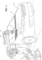
- the applicator die 10 is shown engaged in a process of applying 80 mm wide ribbons 16, 17 of polymeric film to the hood of an automotive vehicle which has been painted and essentially fully assembled, ready for shipment to dealer.
- a first ribbon 16 has been applied across the rearmost portion of the hood 18; i.e., the portion closest to the windshield of the automobile, by moving the robot from right to left along a slightly curved path as shown in Fig. 1 .
- Material is supplied to applicator die 10 under close temperature and flow rate control via supply conduit 20; temperature-controlled liquid is supplied via conduit 21.
- the rate of flow of material from the applicator can, for example, be as much as about 2000 mm/second and the robot 14 moves the applicator die 10 relative to the surface of the hood 18 at about that same rate.
- the spacing between the material outlet of the applicator die 10 and the surface of the hood 18 is about 15 mm, a spacing that, in the die embodiment hereinafter described, causes the ribbon to contact the target surface at the ribbon's maximum width.
- the ratio of polymer to water in the applied material in an illustrative case is approximately 50/50 but will vary with the application. These figures are given by way of example. Robot speed, extrusion rate, spacing and emulsion ratios can all vary according to need.
- the ribbon velocity may, for example, be less than half the robot speed or double the robot speed.
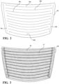
- the material is applied to the surface of the hood in back-and-forth, overlapping ribbons until the forward-most ribbon 16d is applied at which time the applicator is rotated 90° and moved along the ribbon 16e to cover the left edge of the hood and the lateral ribbon ends, as shown in Fig. 2 .
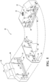
- the applicator is then moved to the top right portion of the hood, as shown in Fig. 3 to apply the final ribbon 16f.
- material is not applied across vehicle body seams.
- the pattern of ribbons in Figs. 2 and 3 is illustrative only.
- the applicator die 10 is referred to as the "applicator die” because the ribbons issued from it are essentially hydraulically laminarized as opposed to atomized or aerated to create a "spray” of particles or droplets.
- the term “hydraulic extrusion” is used herein to mean a laminarized flow or non-atomized fluid propelled by hydraulic pressure rather than by air or other compressible propellant. There are no droplets or spray characteristics in the flow.
- the applicator die 10 is shown to comprise blocks 23 and 28 which are machined out of solid stainless steel, about 31 ⁇ 2" long by 2" high with bottom rounded corners and mitered top corners for weight reduction.
- a shim or metal spacer 26 made of a softer material such as brass, having locator holes 42 so that it may be precisely located on guide pins 40 which are inserted into precisely located holes in the interior surface 41 of the block 23.
- the fourth major element of the applicator die combination is a valve 30 which helps to produce sharper cutoffs as hereinafter explained.
- Block 23 is shown to include a threaded material entry port 22 which extends downwardly to approximately in the center of the block where is communicates with a forwardly directed passage 32 which, in turn, feeds material into a gallery of shallow machined grooves comprising diverging legs 34, 36 and a horizontal cross-leg of groove 38, all of which are of the same depth.
- a horizontal groove 50 is formed in the inside surface 31 of block 28 in full registry with groove 38 in block 23.
- the material applied is polyvinyl acetate in an emulsion containing, in one example, about 50% water and 50% polymer.
- the material is emitted from the applicator die 10 at a width of about 80 mm; i.e., slightly wider than the width of the grooves 38, 50. This is due to the fact that the material fans out slightly. Thereafter, it has been found that the material begins to converge due to surface tension. Accordingly, the spacing between the outlet 58 of the applicator die 10 and the surface upon which the ribbons are being applied is preferably held such that the material is applied at or near the point of maximum thickness; see Fig. 7 .
Landscapes
- Engineering & Computer Science (AREA)
- Mechanical Engineering (AREA)
- Chemical & Material Sciences (AREA)
- Life Sciences & Earth Sciences (AREA)
- Materials Engineering (AREA)
- Wood Science & Technology (AREA)
- Organic Chemistry (AREA)
- Manufacturing & Machinery (AREA)
- Coating Apparatus (AREA)
- Application Of Or Painting With Fluid Materials (AREA)
- Extrusion Moulding Of Plastics Or The Like (AREA)
Description
- This application claims priority to
U.S. Patent Application No. 14/311,533, filed June 23 2014 - Disclosed herein are methods and apparatus for producing and applying polymeric film to the surfaces of an article of manufacture, such as but not limited to an automobile body or a portion thereof, wherein the apparatus includes an applicator configured to hydraulically deliver a laminarized ribbon of polymer-based film with controlled width, thickness and edge characteristics.
- It is known to protect the painted exterior surfaces of automobiles and parts for automobiles with prefabricated and sprayed-on polymeric films to reduce the likelihood of damage during shipment, storage and use. There have been numerous problems associated with the application of such films. Spraying invokes the need to deal with overspray, both in the air and on parts of the article which are not to be coated. Further, it is often necessary to use solvents to remove the film. Prefabrication involves, first, the extrusion of a thin film of plastic in sheet form and, second, the step of laminating the plastic film to a paper backing so it can be rolled up for shipment or storage. When the time comes to apply the film to, for example, an automobile, several laborers are required to unroll the paper-backed film, lay the film over the automobile, remove the paper backing, and smooth the film. The result is a peelable film requiring no solvents or detergents for removal but the manufacturing and application process is labor intensive and, therefore, involves substantial expense.
- It is also known to apply a film or coating of resilient protective polymeric material such as PVC to the rocker panels of automobile bodies thereby to serve as an anti-chip coating. The coating is typically sprayed onto the vehicle rocker panel during the painting phase and dried or cured using, for example, infrared radiation. This sprayed-on method of application requires carefully masking of the body of the vehicle for overspray protection, which is labor-intensive. The masking must also be removed and disposed of, adding further cost to the process.
- In general, this document discloses a manner in which large and small areas of polymer-based film can be applied directly to a component, such as an automobile body component, by the controlled hydraulic emission or "extrusion" of a laminarized ribbon of polymer-based material without atomization and with controlled width, thickness and edge characteristics. This virtually eliminates the problems associated with the prior art spray methods.
- A first aspect of the subject matter described herein is an applicator die according to
claim 1, for producing through a process of laminarized extrusion, a ribbon of fluidized polymeric material in close proximity to a surface to be coated without atomization of the material. The applicator die can be designed and robotically guided to dynamically and consistently lay down a polymeric film of the desired width, length, thickness and edge characteristics in a precise fashion, at low labor cost. Although the examples described herein involve fairly flat surfaces, the applicator can be configured to conform to curved or complex surfaces. The applicator described herein may be said to "hydraulically extrude" laminarized, emulsified polymeric material in a ribbon with well controlled edge-to-edge consistency and thickness. When used to produce a protective layer for an automobile body, the prior art steps of pre-extruding a film and applying the film to a paper backing are eliminated because the robotic arm guiding the applicator can be indexed to produce multiple overlapping ribbons that together cover large uninterrupted areas. Moreover, the applicator hereinafter described in detail can be "ambidextrous" in that it is capable of producing adjacent parallel ribbons of plastic film without indexed rotation for reversal; i.e., the applicator can be reversed in its direction of travel. In addition, the applicator can be used to apply different materials for different purposes to horizontal, vertical and inverted surfaces, whether flat, concave or convex. The resulting film is readily peelable and easily disposed of or recycled. - Another aspect of the subject matter described herein is a robotic system according to claim 4, which includes a die as mentioned here above.
- Another aspect of the subject matter described herein is a method according to claim 8, using the applicator die described above to apply a protective film of a polymeric material, such as an aqueous solution of polyvinyl acetate (PVA), to the finished surfaces of an automobile body or component part therefor, which protective coating, after curing, is readily and easily peelable without the use of solvents of detergents. For the reasons described above, this process is highly efficient due in part to the fact that the application of overlapping polymeric ribbons, applied in a back and forth fashion, can be carried out simply by indexing the applicator and without the need to rotate the applicator 180° between parallel runs. The applicator can essentially be moved relative to the application surface at the speed at which the applied material is emitted from the applicator die. Speeds of about 1500 mm/second have been achieved. However, translation speed will vary from application to application.
- As further described herein, the applicator die comprises a body with an inlet, a long-narrow, slot-like outlet, and a gallery for distributing material from the inlet to the outlet. The outlet configuration can be determined in substantial part by shim or spacer as shown in the illustrative embodiment. The die creates an hydraulic laminarized ribbon of continuous; i.e., non-atomized, material that diverges briefly after emerging from the slot, and then converges or narrows, thus providing latitude in the usable distance between the applicator outlet and the target surface. Die to target spacing is preferably selected to apply the film at its maximum ribbon width. The die can also be configured to control thickness across the ribbon such that it is thinner or thicker near the outside edges than in the middle. When thinner at the edges, ribbon overlap areas may be no more than about equal to the thickness of the ribbon center, thus equalizing drying or curing times for all parts of the final applied film area. The process requirements may vary from job to job, thus calling for configuration variations using the teachings herein.
- Another aspect of the subject matter disclosed herein is a method according to
claim 14, using the aforementioned applicator die in applying an anti-chip coating to, for example, the rocker panels of an automobile body. In this case, the material being applied can be an undirected; i.e., unatomized, laminar-flowing ribbon of emulsified polyvinyl chloride (PVC). In the preferred embodiment, the PVC ribbon is applied over primer previously applied on the rocker panel but before the application of the base and clear coat. It has been determined that it is not necessary to wait for the PVC ribbon to completely dry before the paint or clear coating is applied; i.e., final coatings can be applied "wet-on-wet", greatly reducing production time and totally eliminating the need for masking and spraying as are required in the prior art techniques. - Other advantages, features and characteristics of the subject matter disclosed herein, as well as methods of operation and functions of the related elements of the structure, and the combination of parts and economies of manufacture, will become more apparent upon consideration of the following detailed description and the appended claims with reference to the accompanying drawings, the latter being briefly described hereinafter.
- The description herein makes reference to the accompanying drawings wherein like reference numerals refer to like parts throughout the several views and wherein:
-
Fig. 1 is a perspective view of an applicator die as described herein mounted on a robot arm and used to apply a protective film to the hood of an automobile; -
Fig. 2 is a schematic view of a representative pattern of runs of the robotically moved applicator die in fully covering an automobile hood; -
Fig. 3 is a plan view of the ribbons laid down by the run pattern ofFig. 2 ; -
Fig. 4 is a perspective view of another application of the teachings herein as applied to the use of permanent protective films on rocker panels; -
Fig. 5 is an exploded view of an applicator as described in the following specification; -
Fig. 6 is a sectional view through the application ofFig. 4 ; -
Fig. 7 is a diagram of a material ribbon emerging from the applicator die showing how it converges but allows substantial latitude in the distance from die outlet to target surface; -
Fig. 8 is a block diagram of one of the methods described herein; -
Fig. 9 is a block diagram of another method; and -
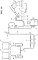
Fig. 10 is a schematic diagram of a complete system. - Referring to
Fig. 1 , an applicator die 10 is shown mounted on the end of anarm 12 of a numerically controlledmulti-axis robot 14 capable of moving the applicator die in three-dimensional space as well as rotating the applicator die about multiple axes. The robot itself is conventional. The applicator die 10 is shown engaged in a process of applying 80 mmwide ribbons Fig. 1 , afirst ribbon 16 has been applied across the rearmost portion of thehood 18; i.e., the portion closest to the windshield of the automobile, by moving the robot from right to left along a slightly curved path as shown inFig. 1 . The robot then indexed thearm 12 toward the front of the vehicle and is shown in the process of applying asecond ribbon 17 moving from left to right across thehood 18 as seen inFig. 1 . Each ribbon is approximately 80 mm wide, is of slightly varying thickness from edge to edge and has an overlap with the adjacent ribbon or ribbons of about 1-7 mm. The preferred thickness profile for this particular application is thinner at the edges than in the center of a ribbon, such that overlap areas are about equal in total thickness to the ribbon thickness at the center. The material being applied is an aqueous solution of polyvinyl acetate (PVA) at a temperature between about 70° and 120° F. and with a viscosity of about 12,000 centipoise. Material is supplied to applicator die 10 under close temperature and flow rate control viasupply conduit 20; temperature-controlled liquid is supplied viaconduit 21. The rate of flow of material from the applicator can, for example, be as much as about 2000 mm/second and therobot 14 moves the applicator die 10 relative to the surface of thehood 18 at about that same rate. The spacing between the material outlet of the applicator die 10 and the surface of thehood 18 is about 15 mm, a spacing that, in the die embodiment hereinafter described, causes the ribbon to contact the target surface at the ribbon's maximum width. The ratio of polymer to water in the applied material in an illustrative case is approximately 50/50 but will vary with the application. These figures are given by way of example. Robot speed, extrusion rate, spacing and emulsion ratios can all vary according to need. The ribbon velocity may, for example, be less than half the robot speed or double the robot speed. - Referring now to
Figs. 2 and 3 , the complete coverage of thehood 18 is achieved using crosswise movements to produceribbons - As shown in
Figs. 2 and 3 , the material is applied to the surface of the hood in back-and-forth, overlapping ribbons until theforward-most ribbon 16d is applied at which time the applicator is rotated 90° and moved along theribbon 16e to cover the left edge of the hood and the lateral ribbon ends, as shown inFig. 2 . The applicator is then moved to the top right portion of the hood, as shown inFig. 3 to apply thefinal ribbon 16f. It will be noted that material is not applied across vehicle body seams. The pattern of ribbons inFigs. 2 and 3 is illustrative only. - Looking now to
Figs. 5 and6 , the applicator die 10 is referred to as the "applicator die" because the ribbons issued from it are essentially hydraulically laminarized as opposed to atomized or aerated to create a "spray" of particles or droplets. The term "hydraulic extrusion" is used herein to mean a laminarized flow or non-atomized fluid propelled by hydraulic pressure rather than by air or other compressible propellant. There are no droplets or spray characteristics in the flow. The applicator die 10 is shown to compriseblocks blocks metal spacer 26 made of a softer material such as brass, having locator holes 42 so that it may be precisely located on guide pins 40 which are inserted into precisely located holes in theinterior surface 41 of theblock 23. The fourth major element of the applicator die combination is avalve 30 which helps to produce sharper cutoffs as hereinafter explained. -
Block 23 is shown to include a threadedmaterial entry port 22 which extends downwardly to approximately in the center of the block where is communicates with a forwardly directedpassage 32 which, in turn, feeds material into a gallery of shallow machined grooves comprising diverginglegs groove 38, all of which are of the same depth. Ahorizontal groove 50 is formed in theinside surface 31 ofblock 28 in full registry withgroove 38 inblock 23. Thespacer 26 fits flush against theinside surface 41 of theblock 23 to cover most of thelegs lower cutout 44 with slightly flaredlegs blocks horizontal grooves bottom outlet 58 of the applicator, as shown inFig. 5 . The flaring of the outlet edges 49 and therounded corners 51 produce aribbon 53 shown inFig. 7 which diverges or broadens immediately after exiting the applicator die 10, but then converges in on itself as a result of surface tension. As shown inFig. 7 , this combination of phenomenon increases the usable distance between the outlet of the applicator die 10 and the target surface. The ribbon preferably meets the target surface at its point of greatest width. -
Block 28 has locator holes 52 which receive the guide pins 40 and locate the block relative to theface 42 of the opposingblock 23, as well as the hidden face of thespacer 26.Block 28 has a singlehorizontal groove 50 which is opposite but coextensive with thegroove 38 within thecutout 44 of thespacer 26 to allow the horizontal fluid chamber created by the twogrooves inside surface 41 of theblock 23. Anaperture 56 cooperates with thevalve 30 to pull thepin 61 out of the flow chamber when cutoff is desired. This rapidly increases chamber volume and correspondingly reduces chamber pressure, resulting in a slight negative pressure with material pull-back, giving rise to a cleaner cutoff. - When applied to a painted surface for protective reasons, the material applied is polyvinyl acetate in an emulsion containing, in one example, about 50% water and 50% polymer. When dispensed, the material is emitted from the applicator die 10 at a width of about 80 mm; i.e., slightly wider than the width of the
grooves outlet 58 of the applicator die 10 and the surface upon which the ribbons are being applied is preferably held such that the material is applied at or near the point of maximum thickness; seeFig. 7 . - As indicated above, the applicator die 10 can be moved at the selected rate over the target surfaces while material is dispersed or extruded therefrom. This gives rise to a short drying time in view of the fact that the thickness of the overlap area is not double that of the overall thickness of the ribbon. When placed in an infrared oven, drying time of about 15 minutes has been shown to be possible at a temperature of 180°. Convective drying can also be used.
- It will be noted that the applicator die 10 is operated in a position which is orthogonal to the target surface rather than angled or tipped in the direction of flow as is the case with typical spray-type, deflective applicators. It will also be noted that the extruded ribbon of material being applied is not particled or atomized; rather, it is a full, continuous ribbon of material moving outwardly and downwardly in laminar form and at a desired rate. Because the applicator is ambidextrous, it does not have to be turned around by rotation between parallel passes in opposite directions and this too, increases the rate at which an automobile body part, for example, a hood, can be covered. After coating, the component goes to an oven for faster curing.
Fig. 7 shows how the film behaves as it leaves the applicator die 10. Because of the diverging shape of the die exit slot, the ribbon diverges at 53 and then converges due to surface tension. The die-to-target spacing is preferably such as to apply the ribbon to the target surface at the point of maximum ribbon width. -
Fig. 8 is a schematic diagram of a method of applying a protective film of an automobile. Thefirst step 100 as indicated by the legend is to apply the emulsion in overlapping and alternating strokes. Thesecond step 102 is to dry the emulsion with infrared radiation. Thethird step 104, in the case of a manufactured automobile, is to ship the protected vehicle and thefinal step 106, typically performed by the dealer, is to peel the coating off of the vehicle and dispose of it in an environmentally appropriate fashion. It peels in one piece and the material can be recycled. - An alternative or additional method of using the applicator die 10 is shown in
Figs. 4 and9 . This method comprises afirst step 200 of applying primer to a rocker panel of anautomotive body 300 in conventional fashion. Thereafter, arobot 302 carrying an applicator die 10 essentially as shown inFigs. 5 and6 and described above is used instep 202 to apply a PVC emulsion to the primed rocker panel as an anti-chip coating. It will be understood that the applicator die 10 has material and coolant supply lines running to it as is the case for the film applicator inFig. 1 . In this case, the polyvinyl chloride solution or emulsion comprises a polymer in an organic solvent applied in a ribbon of the appropriate thickness while the rocker panel is essentially vertical. Temperatures, spacing and application rates are empirically determined in view of the fact that the material has a viscosity of about 50,000 centipoise. It has been found that additional body color paint can be applied over the PVC ribbon instep 204 before it is dried; i.e., paint can be applied "wet-on-wet." The PVC surface produced by the applicator is glossy and uniform in thickness. In this embodiment, only one pass along the rocker panel is required. - There are numerous advantages to the use of this process for the anti-chip coating relative to the prior art process of spraying the coating on the car. Spraying requires the entire vehicle to be masked to protect it against overspray which is highly detrimental to paint finishes. Therefore, this method eliminates the need to mask the vehicle and to remove and dispose of the masking materials. In addition, the laminarized ribbon offers a smooth, glossy appearance as compared to the rough appearance caused by spraying.
-
Fig. 10 is a schematic diagram of a representative system, in this case, for the application of the PVA film as a protective coating. However, the essentials of the system are the same for all applications. As shown in the drawing, material is supplied fromdrums 60, 62 throughlines 64 and 66 which are connected into aY conduit 68 and from there throughparallel legs Conduit 74 flows from theleg 72 through afilter 76 and from there into aheat exchanger 78 which is controlled by atemperature controller 82. Finally, the material flows into the conduits 80 which supply the applicator die 10. Adjacent the applicator die 10 in a standby position is a liquid-filledcleaning standby station 84 with an interior brush which can be activated as necessary. The fluid in the case of the aqueous PVA emulsion is water. Next to thecleaning standby station 84 is a cleaning station 86 where the applicator can be blow-dried. A purge station 90 may be used where desired. - Summarizing, the applicator die 10 uniquely dispenses a ribbon of material of uniform thickness at a high rate of speed and with improved edge control. PVA in a water emulsion is used in the protective film application process of
Fig. 8 . PVC in an organic emulsion is used for the anti-chip coating. The two examples demonstrate that the film ribbons can be applied to horizontal as well as vertical surfaces. They can also be applied to inverted and curved surfaces. - While the invention has been described in connection with what is presently considered to be the most practical and preferred embodiment, it is to be understood that the invention is not to be limited to the disclosed embodiments. The invention is defined according to the appended claims.
Claims (15)
- A die (10) for hydraulically extruding a laminarized polymeric ribbon (16, 17) of film onto the painted surface (18) of an article of manufacture, comprising:a first die block (23) having an interior surface (41) with a straight, elongate gallery groove (38) formed therein adjacent and parallel to the bottom edge;a second die block (28) having an interior surface (31) with a bottom edge and a straight, elongate gallery groove (50) formed therein adjacent and parallel to the bottom edge;a spacer (26) disposed between the first and second die blocks (23, 28); said spacer having a cutout (44);the first and second blocks being joined with gallery grooves therein in registry and the spacer disposed between said interior surfaces;said spacer cutout being located relative to said gallery grooves (38, 50) to create an open volume between the registered gallery grooves to receive film-forming material from an inlet, said spacer cutout defining a slot-like material discharge outlet (58) through which an undivided ribbon (16, 17) of film-forming material can be hydraulically discharged at a predetermined rate; anda material inlet (22) for admitting film-forming polymeric material in emulsion form to said open volume formed by said spacer cutout (44) and gallery grooves (38, 50),wherein the edge surface of the spacer cutout (44) is flared at the opposite sides thereof and has rounded corners (51) to cause the extruded film to flare slightly outwardly during emission, andwherein the elongated gallery groove (38) in the first die block (23) is made of a cross-leg fed with material coming from the material inlet (22) via diverging legs (34, 36), the cross-leg and the diverging legs being machined in the first die block, all with the same depth.
- A die as defined in claim 1 further including a shut-off valve (30) carried by said die (10) for abruptly stopping and starting the flow of said material from said inlet to the open volume formed by said spacer cutout (44) and gallery grooves (38, 50).
- A die as defined in claim 1 wherein the spacer (26) covers most of the diverging legs (34, 36).
- A robotic system for hydraulically applying a laminarized, peelable polymeric protective film to the finished surface of an automobile body part comprising a die (10) as set forth in claim 1 ; said system further comprising a programmable robot (14) adapted to carry said die and cause said die to be translated over the painted surface of an automobile body part.
- The system defined in claim 4 wherein the robot (14) is programmed to move the die (10) relative to the painted surface of the automobile body part in overlapping strokes and at a speed that is equal to the speed at which the polymeric material is emitted from the die.
- A system as defined in claim 5 further including a shut-off valve (30) carried by the die for abruptly starting and stopping the flow of material from the inlet to the galleries (34, 36) of the die (10).
- A system as defined in claim 5 wherein the die further includes means for controlling a temperature of the applicator die.
- A method for hydraulically creating and applying a laminarized film of polymer to the surface of an article of manufacture by hydraulic extrusion comprising wherein the method comprises the steps of:a. supplying a polymer based emulsified material in non-aerated, non-atomized, form to an applicator die (10) according to claim 1;b. causing a non-atomized undivided ribbon of said polymeric emulsion to issue from said die so as to diverge in overall width for a predetermined distance and then begin to converge to a lesser width, due to surface tension and to the shape of the cutout (44) which has flared outlet edges (49) and rounded corners (51);c. using a robot (14) to place the applicator die at a about said predetermined distance from said surface such that the issued ribbon is caused to contact said surface at about a point of maximum width; andd. displacing the applicator die (10) to distribute said ribbon over said surface.
- The method described in claim 8 wherein the die (10) is displaced relative to said surface at a speed equal to the speed at which the emulsified polymeric material issues from said outlet slot.
- The method described in claim 8 comprising the further steps of:a. drying the material applied to said surface by application of infrared radiation or by convection heating and, thereafter;b. removing the dried material by peeling.
- The method defined in claim 8 wherein multiple overlapping ribbons are applied in back and forth fashion.
- The method defined in claim 8 wherein the material is an aqueous emulsion of polyvinyl acetate with a viscosity of about 12,000 centipoise.
- The method defined in claim 9 wherein the spacing between the die (10) and an automobile body part (18) surface onto which the laminarized layer of film is deposited is about 15 mm.
- A method applying an anti-chip coating to a primed surface of an automobile body part comprising the steps of:a. supplying an undirected, polymer based material in un-atomized emulsion form of PVC to an applicator die (10) according to claim 1,;b. using a robot (302) to apply a ribbon of un-atomized emulsion of PVC.
- The method defined in claim 14 further including the step of applying additional body color paint over the applied ribbon polymeric emulsion while at least partial wet.
Applications Claiming Priority (2)
| Application Number | Priority Date | Filing Date | Title |
|---|---|---|---|
| US14/311,533 US10000049B2 (en) | 2014-06-23 | 2014-06-23 | Methods and apparatus for applying protective films |
| PCT/US2015/037130 WO2015200291A2 (en) | 2014-06-23 | 2015-06-23 | Methods and apparatus for applying protective films |
Publications (2)
| Publication Number | Publication Date |
|---|---|
| EP3157686A2 EP3157686A2 (en) | 2017-04-26 |
| EP3157686B1 true EP3157686B1 (en) | 2024-07-03 |
Family
ID=53514414
Family Applications (1)
| Application Number | Title | Priority Date | Filing Date |
|---|---|---|---|
| EP15734513.3A Active EP3157686B1 (en) | 2014-06-23 | 2015-06-23 | Methods and apparatus for applying protective films |
Country Status (7)
| Country | Link |
|---|---|
| US (3) | US10000049B2 (en) |
| EP (1) | EP3157686B1 (en) |
| JP (1) | JP6741601B2 (en) |
| KR (1) | KR102354930B1 (en) |
| CN (1) | CN106660069B (en) |
| BR (1) | BR112016030344A2 (en) |
| WO (1) | WO2015200291A2 (en) |
Families Citing this family (16)
| Publication number | Priority date | Publication date | Assignee | Title |
|---|---|---|---|---|
| US9555441B2 (en) * | 2013-05-03 | 2017-01-31 | Abb Schweiz Ag | Dynamic synchronized masking and coating |
| US10000049B2 (en) | 2014-06-23 | 2018-06-19 | Exel Industries | Methods and apparatus for applying protective films |
| US10315405B2 (en) | 2014-06-23 | 2019-06-11 | Exel Industries | Methods and apparatus for applying protective films |
| CN105751492B (en) * | 2014-12-15 | 2018-05-18 | 广州光宝移动电子部件有限公司 | Three dimensional object and its manufacturing method |
| ES2872623T3 (en) * | 2016-10-06 | 2021-11-02 | Exel Ind | Procedure and Installation for Painting a Component Surface with a Pattern |
| DE102016014944A1 (en) * | 2016-12-14 | 2018-06-14 | Dürr Systems Ag | Coating method and corresponding coating device |
| KR102429007B1 (en) * | 2016-12-14 | 2022-08-03 | 현대자동차 주식회사 | Sealer embrocatioin system |
| CN106944626B (en) * | 2017-04-14 | 2019-10-18 | 华南理工大学 | A kind of complicated flow tube and manufacturing method for the thin Hermetic coating PVC material of automobile |
| CN106914375A (en) * | 2017-05-15 | 2017-07-04 | 惠州市忠邦电子有限公司 | Intelligent bull dispenser system |
| JP7025291B2 (en) * | 2018-06-19 | 2022-02-24 | 株式会社ヒラノテクシード | Coating equipment and how to disassemble the die in the coating equipment |
| DE102018210215B4 (en) | 2018-06-22 | 2022-02-03 | Magna Exteriors Gmbh | Process for producing a plastic component, and plastic component and processing system |
| US20220379337A1 (en) * | 2019-08-30 | 2022-12-01 | Kyocera Corporation | Coating device, coating film, and coating method |
| BR112022016747A2 (en) * | 2020-03-11 | 2022-12-20 | Musashi Eng Inc | FLAT LIQUID FILM FORMING METHOD AND APPARATUS |
| CN112588474B (en) * | 2020-12-04 | 2022-04-15 | 恒大新能源汽车投资控股集团有限公司 | Spraying method for improving appearance of automobile body paint surface |
| KR20240046580A (en) * | 2021-09-02 | 2024-04-09 | 피알시-데소토 인터내쇼날, 인코포레이티드 | Applicator for high viscosity materials |
| CN114516444B (en) * | 2022-03-04 | 2023-11-14 | 江苏创源电子有限公司 | Film pasting device and film pasting method |
Family Cites Families (73)
| Publication number | Priority date | Publication date | Assignee | Title |
|---|---|---|---|---|
| GB1054584A (en) * | 1963-07-02 | |||
| GB1260486A (en) * | 1968-05-20 | 1972-01-19 | Grace W R & Co | Improvements relating to protective coatings |
| GB2145640A (en) | 1983-08-26 | 1985-04-03 | Ucb Sa | Protecting vitreous articles with peelable polymers |
| US5212215A (en) * | 1985-10-29 | 1993-05-18 | Nihon Tokushu Toryo Co., Ltd. | Light anti-chipping coating |
| JPS62154794A (en) * | 1985-12-27 | 1987-07-09 | ノードソン株式会社 | Method of covering mounting circuit board with moisture-proof insulating film |
| US5169900A (en) | 1988-08-05 | 1992-12-08 | Du Pont Canada Inc. | Polyolefin coatings and films having release characteristics |
| AU5107390A (en) * | 1989-01-23 | 1990-08-13 | Robert Howard Boyd | Polymeric aqueous composition for protective coatings |
| US5143949A (en) * | 1989-01-23 | 1992-09-01 | Groco Specialty Coatings Company | Aqueous based, strippable coating composition and method |
| US5244957A (en) * | 1989-08-17 | 1993-09-14 | Exxon Chemical Patents Inc. | Metal protecting compositions |
| US5010131A (en) | 1989-10-20 | 1991-04-23 | Texo Corporation | Barrier coating |
| US5186978B1 (en) | 1990-11-16 | 1999-11-02 | Cal West Equip Co | Protective coating and method of using such coating |
| US5224967A (en) | 1991-01-09 | 1993-07-06 | Lec Tec Corporation | Protective wrap for preventing damage to girdled trees and other plants and method |
| US5330795A (en) | 1991-02-01 | 1994-07-19 | H. B. Fuller Licensing & Financing | Emulsion based coatings and a method using an emulsion based coating to seal asbestos containing soils |
| CA2065092A1 (en) | 1991-04-05 | 1992-10-06 | Masayoshi Kurisu | Curable coating resin composition and information recording medium using the same |
| US5275340A (en) | 1991-06-14 | 1994-01-04 | Spraying Systems Co. | Spray nozzle with recessed deflector surface |
| DE4123588A1 (en) * | 1991-07-17 | 1993-01-21 | Ver Glaswerke Gmbh | METHOD AND DEVICE FOR PRODUCING A VEHICLE WINDOW |
| DE4201800A1 (en) | 1992-01-23 | 1993-07-29 | Wacker Chemie Gmbh | COATING OF SUBSTRATE SURFACES |
| US5281436A (en) | 1992-06-09 | 1994-01-25 | Cal-West Automotive Products | Protective coating composition and method of using such composition |
| US5421897A (en) | 1992-07-17 | 1995-06-06 | Grawe; John | Abatement process for contaminants |
| DE4232554C1 (en) * | 1992-09-29 | 1994-01-05 | Ver Glaswerke Gmbh | Method for producing a glass pane provided with a molded frame made of a thermoplastic polymer and device for carrying out the method |
| DE4315469A1 (en) * | 1993-05-10 | 1994-11-17 | Ver Glaswerke Gmbh | Method and device for extruding a calibrated profile strand from a thermoplastic polymer onto objects |
| US5358397A (en) * | 1993-05-10 | 1994-10-25 | L&L Products, Inc. | Apparatus for extruding flowable materials |
| US5382395A (en) * | 1993-05-14 | 1995-01-17 | Admiral Equipment Co. | Profile extrusion apparatus and method for extruding a profile |
| US7018943B2 (en) | 1994-10-27 | 2006-03-28 | Asml Holding N.V. | Method of uniformly coating a substrate |
| CA2205833C (en) * | 1994-11-23 | 2001-01-23 | Alcan International Limited | Coating strip material with protective/decorative layers while avoiding use of solvents |
| DE4442670C1 (en) * | 1994-11-30 | 1996-05-30 | Atlas Vertriebs Gmbh | Application of self adhesive film to vehicles |
| JP2764557B2 (en) * | 1995-01-27 | 1998-06-11 | 井上金属工業株式会社 | Coating method and coating device |
| US5505995A (en) * | 1995-02-02 | 1996-04-09 | Minnesota Mining And Manufacturing Company | Method and apparatus for coating substrates using an air knife |
| AU4283396A (en) * | 1995-02-02 | 1996-08-21 | Minnesota Mining And Manufacturing Company | Method and apparatus for applying thin fluid coatings |
| US5548017A (en) | 1995-04-04 | 1996-08-20 | Air Products And Chemicals, Inc. | Release coating for pressure sensitive adhesives |
| JPH08276152A (en) * | 1995-04-05 | 1996-10-22 | Kansai Paint Co Ltd | Coating method for paint film of automobile exterior body panel with temporarily protective paint |
| US6254712B1 (en) | 1998-12-08 | 2001-07-03 | Avery Dennison Corporation | Extrusion coating process for making high transparency protective and decorative films |
| JPH0992134A (en) * | 1995-09-22 | 1997-04-04 | Dainippon Printing Co Ltd | Nozzle application method and device |
| US6124044A (en) | 1995-10-27 | 2000-09-26 | Cal-West Equipment Company, Inc. | Polymeric peel-off coating compositions and methods of use thereof |
| US6187377B1 (en) * | 1996-05-29 | 2001-02-13 | Honda Giken Kogyo Kabushiki Kaisha | Process for forming protective film on coated surface of automobile |
| US5736470A (en) | 1996-06-25 | 1998-04-07 | Omega Research, Inc. | Pressure sensitive adhesive article and method of making |
| US5824734A (en) | 1996-07-10 | 1998-10-20 | Air Products And Chemicals, Inc. | Waterborne coating compositions |
| US5979794A (en) | 1997-05-13 | 1999-11-09 | Ingersoll-Rand Company | Two-part stream dispensing for high viscosity materials |
| AT409638B (en) * | 1998-11-17 | 2002-09-25 | Solutia Austria Gmbh | ADHESIVE IMPROVEMENT FOR PAINT COATINGS |
| JP4324998B2 (en) * | 1998-11-24 | 2009-09-02 | 東レ株式会社 | Coating apparatus and coating method, and plasma display manufacturing method and manufacturing apparatus |
| JP4240641B2 (en) * | 1999-03-05 | 2009-03-18 | 東レ株式会社 | Plasma display manufacturing method and paste coating apparatus |
| AU4986300A (en) | 1999-05-07 | 2000-11-21 | Designetics | Automated priming station |
| DE19936790A1 (en) * | 1999-08-10 | 2001-02-15 | Nordson Corp Westlake | Method and device for producing a removable protective layer for surfaces, in particular for painted surfaces of motor vehicle bodies |
| DE19956335A1 (en) * | 1999-11-23 | 2001-05-31 | Sca Schucker Gmbh & Co | Method for producing motor vehicle bodywork components with a strip of insulating material consists of applying such a material in a viscous state and providing the resultant strip with a cover layer |
| DE10031258A1 (en) | 2000-06-27 | 2002-01-10 | Basf Ag | Curable aqueous polyurethane dispersions |
| WO2002024346A1 (en) * | 2000-09-25 | 2002-03-28 | Cal-West Specialty Coatings, Inc. | Polymeric peel-off coating compositions and method of use thereof |
| JP2002239436A (en) * | 2001-02-15 | 2002-08-27 | Toray Ind Inc | Coating apparatus |
| KR20040017271A (en) | 2001-07-03 | 2004-02-26 | 동경 엘렉트론 주식회사 | Coating device and coating method |
| US7043815B2 (en) * | 2002-01-25 | 2006-05-16 | L & L Products, Inc. | Method for applying flowable materials |
| JP3957640B2 (en) * | 2002-02-21 | 2007-08-15 | アイシン化工株式会社 | Wide slit nozzle and coating method with wide slit nozzle |
| CN100400181C (en) * | 2002-12-27 | 2008-07-09 | 本田技研工业株式会社 | Protective layer forming material application system, object to be treated, strippable protective layer and method for protecting surface of object to be treated |
| DE10318836A1 (en) * | 2003-04-25 | 2004-11-11 | Voith Paper Patent Gmbh | Process for coating a cylindrical body |
| JP2005116553A (en) * | 2003-10-02 | 2005-04-28 | Tokyo Electron Ltd | Device and method for forming coating film |
| EP1550703A1 (en) * | 2004-01-05 | 2005-07-06 | Sika Technology AG | Protective film from hot melt adhesive, process and apparatus for its application |
| US7291362B2 (en) * | 2004-01-20 | 2007-11-06 | 3M Innovative Properties Company | Method and apparatus for controlling coating width |
| DE102004042541A1 (en) * | 2004-01-29 | 2006-03-23 | Gunter Prediger | Apparatus for the production of resin coatings |
| US7871669B2 (en) * | 2004-08-30 | 2011-01-18 | E.I. Du Pont De Nemours And Company | Method for achieving a durable two-tone finish on a vehicle |
| EP1861209A1 (en) * | 2005-03-11 | 2007-12-05 | Ryco Book Protection Services Limited | Method and apparatus for indirectly coating a substrate with a hot flowable viscous adhesive |
| JP2006334512A (en) * | 2005-06-02 | 2006-12-14 | Honda Motor Co Ltd | Coating method of coating film protective layer, and its coating nozzle |
| JP4185084B2 (en) * | 2005-09-26 | 2008-11-19 | 本田技研工業株式会社 | Water-based paint application method and application nozzle |
| DE102006060398A1 (en) * | 2006-12-20 | 2008-06-26 | Mankiewicz Gebr. & Co (Gmbh & Co Kg) | Fluid coating e.g. finish paint, applying device for surface of body of e.g. passenger car, has nozzle applying fluid on surface by air flow, and unit producing air flow, which deflects fluid between nozzle and surface |
| EP2089222A4 (en) * | 2006-11-10 | 2010-12-01 | Cal West Specialty Coatings In | Peel-off coating compositions |
| JP2008253966A (en) * | 2007-04-09 | 2008-10-23 | Toyota Motor Corp | Die for paste application |
| JP5007168B2 (en) * | 2007-07-10 | 2012-08-22 | 日東電工株式会社 | Die coater adjusting method and optical film manufacturing method |
| DE102010011095A1 (en) * | 2010-03-11 | 2010-10-28 | Daimler Ag | Nozzle for applying liquid, particularly high-viscous materials, particularly seamed sealing materials for motor vehicle body components, on component, has base body with slit-shaped channel |
| JP5060599B2 (en) * | 2010-06-29 | 2012-10-31 | トヨタ自動車株式会社 | High viscosity paint application nozzle |
| US8752501B2 (en) * | 2010-07-29 | 2014-06-17 | Corning Incorporated | Systems and methods for dispensing a fluid |
| US20120135194A1 (en) * | 2010-11-24 | 2012-05-31 | Honda Motor Co., Ltd. | High-viscosity material application device, high-viscosity material application method, and high-viscosity material coating |
| JP5880151B2 (en) * | 2012-03-07 | 2016-03-08 | 三菱マテリアル株式会社 | Application tool |
| CN202762603U (en) * | 2012-08-13 | 2013-03-06 | 广东生益科技股份有限公司 | Slit type coating head |
| JP5892017B2 (en) | 2012-09-19 | 2016-03-23 | マツダ株式会社 | Coating method and coating apparatus |
| US10000049B2 (en) | 2014-06-23 | 2018-06-19 | Exel Industries | Methods and apparatus for applying protective films |
| US10315405B2 (en) * | 2014-06-23 | 2019-06-11 | Exel Industries | Methods and apparatus for applying protective films |
-
2014
- 2014-06-23 US US14/311,533 patent/US10000049B2/en active Active
-
2015
- 2015-06-23 EP EP15734513.3A patent/EP3157686B1/en active Active
- 2015-06-23 KR KR1020167036028A patent/KR102354930B1/en active IP Right Grant
- 2015-06-23 CN CN201580033845.3A patent/CN106660069B/en active Active
- 2015-06-23 JP JP2016574375A patent/JP6741601B2/en active Active
- 2015-06-23 BR BR112016030344A patent/BR112016030344A2/en not_active IP Right Cessation
- 2015-06-23 WO PCT/US2015/037130 patent/WO2015200291A2/en active Application Filing
-
2018
- 2018-03-02 US US15/910,367 patent/US10696033B2/en not_active Expired - Fee Related
-
2020
- 2020-04-24 US US16/857,324 patent/US20200254745A1/en not_active Abandoned
Also Published As
| Publication number | Publication date |
|---|---|
| US20180186143A1 (en) | 2018-07-05 |
| BR112016030344A2 (en) | 2017-08-22 |
| EP3157686A2 (en) | 2017-04-26 |
| KR20170021257A (en) | 2017-02-27 |
| CN106660069B (en) | 2021-02-19 |
| WO2015200291A2 (en) | 2015-12-30 |
| KR102354930B1 (en) | 2022-01-24 |
| US10696033B2 (en) | 2020-06-30 |
| WO2015200291A3 (en) | 2016-06-02 |
| JP2017522178A (en) | 2017-08-10 |
| WO2015200291A4 (en) | 2016-07-21 |
| US20200254745A1 (en) | 2020-08-13 |
| JP6741601B2 (en) | 2020-08-19 |
| CN106660069A (en) | 2017-05-10 |
| US10000049B2 (en) | 2018-06-19 |
| US20150367620A1 (en) | 2015-12-24 |
Similar Documents
| Publication | Publication Date | Title |
|---|---|---|
| EP3157686B1 (en) | Methods and apparatus for applying protective films | |
| US10315405B2 (en) | Methods and apparatus for applying protective films | |
| JP2017522178A5 (en) | ||
| IL272882B (en) | Automated wall finishing system and method | |
| KR102452463B1 (en) | Method and installation for painting a surface of a component with a pattern | |
| CA2839925C (en) | Coating nozzle for high-viscosity paint | |
| WO2001066266A1 (en) | Method and apparatus for extruding a coating upon a substrate surface | |
| JP2003506210A (en) | Method and apparatus for forming a peelable protective layer for surfaces, in particular lacquered surfaces of motor vehicle bodies | |
| US20040217202A1 (en) | Airless conformal coating apparatus and method | |
| US4946715A (en) | Method for producing faux finishes on non-porous surfaces | |
| JP2003135998A (en) | Equipment and method for multicolor pattern coating | |
| JP2001025701A (en) | Coating method and spray gun | |
| JP3225631B2 (en) | Painting equipment | |
| JP3478523B2 (en) | Thick-coating spray nozzle device, coating method, and automobile body | |
| US20190247882A1 (en) | Methods and apparatus for applying protective films | |
| JPS5822262B2 (en) | Electrostatic painting method | |
| JP2831288B2 (en) | Apparatus for applying strippable paint to painted surfaces of automobiles | |
| JP3058313B2 (en) | How to apply strippable paint to painted surfaces of automobiles | |
| JP2000070841A (en) | Coating of alc corner panel | |
| JP2000044365A (en) | Coating of surface of aerated lightweight concrete | |
| JPH06226196A (en) | Coating method | |
| JPH0236304B2 (en) | ||
| JPH0234667B2 (en) | ||
| JPS6345865B2 (en) | ||
| JPS59127676A (en) | Coater for long article |
Legal Events
| Date | Code | Title | Description |
|---|---|---|---|
| STAA | Information on the status of an ep patent application or granted ep patent |
Free format text: STATUS: THE INTERNATIONAL PUBLICATION HAS BEEN MADE |
|
| PUAI | Public reference made under article 153(3) epc to a published international application that has entered the european phase |
Free format text: ORIGINAL CODE: 0009012 |
|
| STAA | Information on the status of an ep patent application or granted ep patent |
Free format text: STATUS: REQUEST FOR EXAMINATION WAS MADE |
|
| 17P | Request for examination filed |
Effective date: 20161221 |
|
| AK | Designated contracting states |
Kind code of ref document: A2 Designated state(s): AL AT BE BG CH CY CZ DE DK EE ES FI FR GB GR HR HU IE IS IT LI LT LU LV MC MK MT NL NO PL PT RO RS SE SI SK SM TR |
|
| AX | Request for extension of the european patent |
Extension state: BA ME |
|
| DAV | Request for validation of the european patent (deleted) | ||
| DAX | Request for extension of the european patent (deleted) | ||
| STAA | Information on the status of an ep patent application or granted ep patent |
Free format text: STATUS: EXAMINATION IS IN PROGRESS |
|
| 17Q | First examination report despatched |
Effective date: 20180705 |
|
| STAA | Information on the status of an ep patent application or granted ep patent |
Free format text: STATUS: EXAMINATION IS IN PROGRESS |
|
| STAA | Information on the status of an ep patent application or granted ep patent |
Free format text: STATUS: EXAMINATION IS IN PROGRESS |
|
| GRAP | Despatch of communication of intention to grant a patent |
Free format text: ORIGINAL CODE: EPIDOSNIGR1 |
|
| STAA | Information on the status of an ep patent application or granted ep patent |
Free format text: STATUS: GRANT OF PATENT IS INTENDED |
|
| RIC1 | Information provided on ipc code assigned before grant |
Ipc: B05D 1/32 20060101ALN20240131BHEP Ipc: B05C 5/02 20060101ALI20240131BHEP Ipc: B05D 1/26 20060101ALI20240131BHEP Ipc: B05D 5/00 20060101AFI20240131BHEP |
|
| RIC1 | Information provided on ipc code assigned before grant |
Ipc: B05D 1/32 20060101ALN20240206BHEP Ipc: B05C 5/02 20060101ALI20240206BHEP Ipc: B05D 1/26 20060101ALI20240206BHEP Ipc: B05D 5/00 20060101AFI20240206BHEP |
|
| INTG | Intention to grant announced |
Effective date: 20240223 |
|
| GRAS | Grant fee paid |
Free format text: ORIGINAL CODE: EPIDOSNIGR3 |
|
| GRAA | (expected) grant |
Free format text: ORIGINAL CODE: 0009210 |
|
| STAA | Information on the status of an ep patent application or granted ep patent |
Free format text: STATUS: THE PATENT HAS BEEN GRANTED |
|
| AK | Designated contracting states |
Kind code of ref document: B1 Designated state(s): AL AT BE BG CH CY CZ DE DK EE ES FI FR GB GR HR HU IE IS IT LI LT LU LV MC MK MT NL NO PL PT RO RS SE SI SK SM TR |
|
| REG | Reference to a national code |
Ref country code: CH Ref legal event code: EP |
|
| REG | Reference to a national code |
Ref country code: DE Ref legal event code: R096 Ref document number: 602015089103 Country of ref document: DE |