EP3157683B1 - Générateur d'aérosol et dispositif de distribution d'aérosol comprenant le générateur - Google Patents
Générateur d'aérosol et dispositif de distribution d'aérosol comprenant le générateur Download PDFInfo
- Publication number
- EP3157683B1 EP3157683B1 EP15733654.6A EP15733654A EP3157683B1 EP 3157683 B1 EP3157683 B1 EP 3157683B1 EP 15733654 A EP15733654 A EP 15733654A EP 3157683 B1 EP3157683 B1 EP 3157683B1
- Authority
- EP
- European Patent Office
- Prior art keywords
- aerosol
- aerosol generator
- fluid
- vibratable
- vibratable element
- Prior art date
- Legal status (The legal status is an assumption and is not a legal conclusion. Google has not performed a legal analysis and makes no representation as to the accuracy of the status listed.)
- Active
Links
- 239000000443 aerosol Substances 0.000 title claims description 128
- 239000012530 fluid Substances 0.000 claims description 75
- 239000012528 membrane Substances 0.000 claims description 32
- 239000000463 material Substances 0.000 claims description 12
- 239000007788 liquid Substances 0.000 description 39
- -1 polypropylene Polymers 0.000 description 24
- 150000001875 compounds Chemical class 0.000 description 19
- 238000007789 sealing Methods 0.000 description 12
- 239000004020 conductor Substances 0.000 description 11
- 239000004033 plastic Substances 0.000 description 9
- 229920003023 plastic Polymers 0.000 description 9
- 239000000126 substance Substances 0.000 description 7
- 229920002725 thermoplastic elastomer Polymers 0.000 description 7
- 239000003814 drug Substances 0.000 description 6
- 229910052751 metal Inorganic materials 0.000 description 6
- 239000002184 metal Substances 0.000 description 6
- 238000003466 welding Methods 0.000 description 6
- 229920001971 elastomer Polymers 0.000 description 5
- 230000033001 locomotion Effects 0.000 description 5
- 239000000203 mixture Substances 0.000 description 5
- LRFVTYWOQMYALW-UHFFFAOYSA-N 9H-xanthine Chemical compound O=C1NC(=O)NC2=C1NC=N2 LRFVTYWOQMYALW-UHFFFAOYSA-N 0.000 description 4
- 229930182555 Penicillin Natural products 0.000 description 4
- 239000003242 anti bacterial agent Substances 0.000 description 4
- 230000002421 anti-septic effect Effects 0.000 description 4
- 229940088710 antibiotic agent Drugs 0.000 description 4
- 239000004599 antimicrobial Substances 0.000 description 4
- 229940064004 antiseptic throat preparations Drugs 0.000 description 4
- 239000003795 chemical substances by application Substances 0.000 description 4
- 238000000034 method Methods 0.000 description 4
- 230000010355 oscillation Effects 0.000 description 4
- 239000000419 plant extract Substances 0.000 description 4
- 230000008569 process Effects 0.000 description 4
- 102000004196 processed proteins & peptides Human genes 0.000 description 4
- 108090000765 processed proteins & peptides Proteins 0.000 description 4
- 108090000623 proteins and genes Proteins 0.000 description 4
- 102000004169 proteins and genes Human genes 0.000 description 4
- 239000004094 surface-active agent Substances 0.000 description 4
- 108091034117 Oligonucleotide Proteins 0.000 description 3
- JGSARLDLIJGVTE-MBNYWOFBSA-N Penicillin G Chemical compound N([C@H]1[C@H]2SC([C@@H](N2C1=O)C(O)=O)(C)C)C(=O)CC1=CC=CC=C1 JGSARLDLIJGVTE-MBNYWOFBSA-N 0.000 description 3
- JLCPHMBAVCMARE-UHFFFAOYSA-N [3-[[3-[[3-[[3-[[3-[[3-[[3-[[3-[[3-[[3-[[3-[[5-(2-amino-6-oxo-1H-purin-9-yl)-3-[[3-[[3-[[3-[[3-[[3-[[5-(2-amino-6-oxo-1H-purin-9-yl)-3-[[5-(2-amino-6-oxo-1H-purin-9-yl)-3-hydroxyoxolan-2-yl]methoxy-hydroxyphosphoryl]oxyoxolan-2-yl]methoxy-hydroxyphosphoryl]oxy-5-(5-methyl-2,4-dioxopyrimidin-1-yl)oxolan-2-yl]methoxy-hydroxyphosphoryl]oxy-5-(6-aminopurin-9-yl)oxolan-2-yl]methoxy-hydroxyphosphoryl]oxy-5-(6-aminopurin-9-yl)oxolan-2-yl]methoxy-hydroxyphosphoryl]oxy-5-(6-aminopurin-9-yl)oxolan-2-yl]methoxy-hydroxyphosphoryl]oxy-5-(6-aminopurin-9-yl)oxolan-2-yl]methoxy-hydroxyphosphoryl]oxyoxolan-2-yl]methoxy-hydroxyphosphoryl]oxy-5-(5-methyl-2,4-dioxopyrimidin-1-yl)oxolan-2-yl]methoxy-hydroxyphosphoryl]oxy-5-(4-amino-2-oxopyrimidin-1-yl)oxolan-2-yl]methoxy-hydroxyphosphoryl]oxy-5-(5-methyl-2,4-dioxopyrimidin-1-yl)oxolan-2-yl]methoxy-hydroxyphosphoryl]oxy-5-(5-methyl-2,4-dioxopyrimidin-1-yl)oxolan-2-yl]methoxy-hydroxyphosphoryl]oxy-5-(6-aminopurin-9-yl)oxolan-2-yl]methoxy-hydroxyphosphoryl]oxy-5-(6-aminopurin-9-yl)oxolan-2-yl]methoxy-hydroxyphosphoryl]oxy-5-(4-amino-2-oxopyrimidin-1-yl)oxolan-2-yl]methoxy-hydroxyphosphoryl]oxy-5-(4-amino-2-oxopyrimidin-1-yl)oxolan-2-yl]methoxy-hydroxyphosphoryl]oxy-5-(4-amino-2-oxopyrimidin-1-yl)oxolan-2-yl]methoxy-hydroxyphosphoryl]oxy-5-(6-aminopurin-9-yl)oxolan-2-yl]methoxy-hydroxyphosphoryl]oxy-5-(4-amino-2-oxopyrimidin-1-yl)oxolan-2-yl]methyl [5-(6-aminopurin-9-yl)-2-(hydroxymethyl)oxolan-3-yl] hydrogen phosphate Polymers Cc1cn(C2CC(OP(O)(=O)OCC3OC(CC3OP(O)(=O)OCC3OC(CC3O)n3cnc4c3nc(N)[nH]c4=O)n3cnc4c3nc(N)[nH]c4=O)C(COP(O)(=O)OC3CC(OC3COP(O)(=O)OC3CC(OC3COP(O)(=O)OC3CC(OC3COP(O)(=O)OC3CC(OC3COP(O)(=O)OC3CC(OC3COP(O)(=O)OC3CC(OC3COP(O)(=O)OC3CC(OC3COP(O)(=O)OC3CC(OC3COP(O)(=O)OC3CC(OC3COP(O)(=O)OC3CC(OC3COP(O)(=O)OC3CC(OC3COP(O)(=O)OC3CC(OC3COP(O)(=O)OC3CC(OC3COP(O)(=O)OC3CC(OC3COP(O)(=O)OC3CC(OC3COP(O)(=O)OC3CC(OC3COP(O)(=O)OC3CC(OC3CO)n3cnc4c(N)ncnc34)n3ccc(N)nc3=O)n3cnc4c(N)ncnc34)n3ccc(N)nc3=O)n3ccc(N)nc3=O)n3ccc(N)nc3=O)n3cnc4c(N)ncnc34)n3cnc4c(N)ncnc34)n3cc(C)c(=O)[nH]c3=O)n3cc(C)c(=O)[nH]c3=O)n3ccc(N)nc3=O)n3cc(C)c(=O)[nH]c3=O)n3cnc4c3nc(N)[nH]c4=O)n3cnc4c(N)ncnc34)n3cnc4c(N)ncnc34)n3cnc4c(N)ncnc34)n3cnc4c(N)ncnc34)O2)c(=O)[nH]c1=O JLCPHMBAVCMARE-UHFFFAOYSA-N 0.000 description 3
- 239000008186 active pharmaceutical agent Substances 0.000 description 3
- 239000000853 adhesive Substances 0.000 description 3
- 230000001070 adhesive effect Effects 0.000 description 3
- 239000012080 ambient air Substances 0.000 description 3
- 239000000043 antiallergic agent Substances 0.000 description 3
- 229940121375 antifungal agent Drugs 0.000 description 3
- 229960005475 antiinfective agent Drugs 0.000 description 3
- 239000003443 antiviral agent Substances 0.000 description 3
- 229940121357 antivirals Drugs 0.000 description 3
- 239000000919 ceramic Substances 0.000 description 3
- 239000000850 decongestant Substances 0.000 description 3
- 229940124581 decongestants Drugs 0.000 description 3
- 201000010099 disease Diseases 0.000 description 3
- 208000037265 diseases, disorders, signs and symptoms Diseases 0.000 description 3
- 229940079593 drug Drugs 0.000 description 3
- 239000003172 expectorant agent Substances 0.000 description 3
- 239000003862 glucocorticoid Substances 0.000 description 3
- PCHJSUWPFVWCPO-UHFFFAOYSA-N gold Chemical compound [Au] PCHJSUWPFVWCPO-UHFFFAOYSA-N 0.000 description 3
- 229910052737 gold Inorganic materials 0.000 description 3
- 239000010931 gold Substances 0.000 description 3
- 238000001746 injection moulding Methods 0.000 description 3
- 229960005015 local anesthetics Drugs 0.000 description 3
- 230000000510 mucolytic effect Effects 0.000 description 3
- 229940066491 mucolytics Drugs 0.000 description 3
- 229940021182 non-steroidal anti-inflammatory drug Drugs 0.000 description 3
- 229920001296 polysiloxane Polymers 0.000 description 3
- 239000005060 rubber Substances 0.000 description 3
- 229910001220 stainless steel Inorganic materials 0.000 description 3
- 239000010935 stainless steel Substances 0.000 description 3
- 229940037128 systemic glucocorticoids Drugs 0.000 description 3
- 230000001225 therapeutic effect Effects 0.000 description 3
- 238000011282 treatment Methods 0.000 description 3
- 239000011782 vitamin Substances 0.000 description 3
- 229940088594 vitamin Drugs 0.000 description 3
- 229930003231 vitamin Natural products 0.000 description 3
- 235000013343 vitamin Nutrition 0.000 description 3
- JWZZKOKVBUJMES-UHFFFAOYSA-N (+-)-Isoprenaline Chemical compound CC(C)NCC(O)C1=CC=C(O)C(O)=C1 JWZZKOKVBUJMES-UHFFFAOYSA-N 0.000 description 2
- KWGRBVOPPLSCSI-WPRPVWTQSA-N (-)-ephedrine Chemical compound CN[C@@H](C)[C@H](O)C1=CC=CC=C1 KWGRBVOPPLSCSI-WPRPVWTQSA-N 0.000 description 2
- CNIIGCLFLJGOGP-UHFFFAOYSA-N 2-(1-naphthalenylmethyl)-4,5-dihydro-1H-imidazole Chemical compound C=1C=CC2=CC=CC=C2C=1CC1=NCCN1 CNIIGCLFLJGOGP-UHFFFAOYSA-N 0.000 description 2
- HZZVJAQRINQKSD-UHFFFAOYSA-N Clavulanic acid Natural products OC(=O)C1C(=CCO)OC2CC(=O)N21 HZZVJAQRINQKSD-UHFFFAOYSA-N 0.000 description 2
- AOJJSUZBOXZQNB-TZSSRYMLSA-N Doxorubicin Chemical compound O([C@H]1C[C@@](O)(CC=2C(O)=C3C(=O)C=4C=CC=C(C=4C(=O)C3=C(O)C=21)OC)C(=O)CO)[C@H]1C[C@H](N)[C@H](O)[C@H](C)O1 AOJJSUZBOXZQNB-TZSSRYMLSA-N 0.000 description 2
- ULGZDMOVFRHVEP-RWJQBGPGSA-N Erythromycin Chemical compound O([C@@H]1[C@@H](C)C(=O)O[C@@H]([C@@]([C@H](O)[C@@H](C)C(=O)[C@H](C)C[C@@](C)(O)[C@H](O[C@H]2[C@@H]([C@H](C[C@@H](C)O2)N(C)C)O)[C@H]1C)(C)O)CC)[C@H]1C[C@@](C)(OC)[C@@H](O)[C@H](C)O1 ULGZDMOVFRHVEP-RWJQBGPGSA-N 0.000 description 2
- 229920001499 Heparinoid Polymers 0.000 description 2
- FBOZXECLQNJBKD-ZDUSSCGKSA-N L-methotrexate Chemical compound C=1N=C2N=C(N)N=C(N)C2=NC=1CN(C)C1=CC=C(C(=O)N[C@@H](CCC(O)=O)C(O)=O)C=C1 FBOZXECLQNJBKD-ZDUSSCGKSA-N 0.000 description 2
- MVTQIFVKRXBCHS-SMMNFGSLSA-N N-[(3S,6S,12R,15S,16R,19S,22S)-3-benzyl-12-ethyl-4,16-dimethyl-2,5,11,14,18,21,24-heptaoxo-19-phenyl-17-oxa-1,4,10,13,20-pentazatricyclo[20.4.0.06,10]hexacosan-15-yl]-3-hydroxypyridine-2-carboxamide (10R,11R,12E,17E,19E,21S)-21-hydroxy-11,19-dimethyl-10-propan-2-yl-9,26-dioxa-3,15,28-triazatricyclo[23.2.1.03,7]octacosa-1(27),6,12,17,19,25(28)-hexaene-2,8,14,23-tetrone Chemical compound CC(C)[C@H]1OC(=O)C2=CCCN2C(=O)c2coc(CC(=O)C[C@H](O)\C=C(/C)\C=C\CNC(=O)\C=C\[C@H]1C)n2.CC[C@H]1NC(=O)[C@@H](NC(=O)c2ncccc2O)[C@@H](C)OC(=O)[C@@H](NC(=O)[C@@H]2CC(=O)CCN2C(=O)[C@H](Cc2ccccc2)N(C)C(=O)[C@@H]2CCCN2C1=O)c1ccccc1 MVTQIFVKRXBCHS-SMMNFGSLSA-N 0.000 description 2
- 229930193140 Neomycin Natural products 0.000 description 2
- CZWCKYRVOZZJNM-UHFFFAOYSA-N Prasterone sodium sulfate Natural products C1C(OS(O)(=O)=O)CCC2(C)C3CCC(C)(C(CC4)=O)C4C3CC=C21 CZWCKYRVOZZJNM-UHFFFAOYSA-N 0.000 description 2
- 239000004365 Protease Substances 0.000 description 2
- KGZHFKDNSAEOJX-WIFQYKSHSA-N Ramoplanin Chemical compound C([C@H]1C(=O)N[C@H](CCCN)C(=O)N[C@H](C(=O)N[C@@H](C(=O)N[C@H](C(=O)NCC(=O)N[C@@H](CC(C)C)C(=O)N[C@H](C)C(=O)N[C@H](C(=O)O[C@@H]([C@@H](C(N[C@@H](C(=O)N[C@H](CCCN)C(=O)N[C@@H](C(=O)N[C@H](C(=O)N[C@@H](C(=O)N[C@H](C(=O)N1)[C@H](C)O)C=1C=CC(O)=CC=1)C=1C=CC(O)=CC=1)[C@@H](C)O)C=1C=CC(O)=CC=1)=O)NC(=O)[C@H](CC(N)=O)NC(=O)\C=C/C=C/CC(C)C)C(N)=O)C=1C=C(Cl)C(O)=CC=1)C=1C=CC(O)=CC=1)[C@@H](C)O)C=1C=CC(O[C@@H]2[C@H]([C@@H](O)[C@H](O)[C@@H](CO)O2)O[C@@H]2[C@H]([C@@H](O)[C@H](O)[C@@H](CO)O2)O)=CC=1)C1=CC=CC=C1 KGZHFKDNSAEOJX-WIFQYKSHSA-N 0.000 description 2
- HUCJFAOMUPXHDK-UHFFFAOYSA-N Xylometazoline Chemical compound CC1=CC(C(C)(C)C)=CC(C)=C1CC1=NCCN1 HUCJFAOMUPXHDK-UHFFFAOYSA-N 0.000 description 2
- 230000002411 adverse Effects 0.000 description 2
- 239000003570 air Substances 0.000 description 2
- POJWUDADGALRAB-UHFFFAOYSA-N allantoin Chemical compound NC(=O)NC1NC(=O)NC1=O POJWUDADGALRAB-UHFFFAOYSA-N 0.000 description 2
- 229960003022 amoxicillin Drugs 0.000 description 2
- LSQZJLSUYDQPKJ-NJBDSQKTSA-N amoxicillin Chemical compound C1([C@@H](N)C(=O)N[C@H]2[C@H]3SC([C@@H](N3C2=O)C(O)=O)(C)C)=CC=C(O)C=C1 LSQZJLSUYDQPKJ-NJBDSQKTSA-N 0.000 description 2
- 230000003110 anti-inflammatory effect Effects 0.000 description 2
- 239000003963 antioxidant agent Substances 0.000 description 2
- 208000006673 asthma Diseases 0.000 description 2
- BLFLLBZGZJTVJG-UHFFFAOYSA-N benzocaine Chemical compound CCOC(=O)C1=CC=C(N)C=C1 BLFLLBZGZJTVJG-UHFFFAOYSA-N 0.000 description 2
- RYYVLZVUVIJVGH-UHFFFAOYSA-N caffeine Chemical compound CN1C(=O)N(C)C(=O)C2=C1N=CN2C RYYVLZVUVIJVGH-UHFFFAOYSA-N 0.000 description 2
- 239000000812 cholinergic antagonist Substances 0.000 description 2
- MYSWGUAQZAJSOK-UHFFFAOYSA-N ciprofloxacin Chemical compound C12=CC(N3CCNCC3)=C(F)C=C2C(=O)C(C(=O)O)=CN1C1CC1 MYSWGUAQZAJSOK-UHFFFAOYSA-N 0.000 description 2
- 229960003324 clavulanic acid Drugs 0.000 description 2
- HZZVJAQRINQKSD-PBFISZAISA-N clavulanic acid Chemical compound OC(=O)[C@H]1C(=C/CO)/O[C@@H]2CC(=O)N21 HZZVJAQRINQKSD-PBFISZAISA-N 0.000 description 2
- LKJYEAJRWPUOGW-UHFFFAOYSA-N clerocidin Chemical compound CC1CCC(C(=CCC2)C=O)(C)C2C1(C)CC(C1(OC1)C1(O)O2)OC1OC1(O)C2OC(CC2(C)C3C(C(=CCC3)C=O)(C)CCC2C)C11CO1 LKJYEAJRWPUOGW-UHFFFAOYSA-N 0.000 description 2
- 239000013078 crystal Substances 0.000 description 2
- 239000000824 cytostatic agent Substances 0.000 description 2
- 230000001085 cytostatic effect Effects 0.000 description 2
- 229960002488 dalbavancin Drugs 0.000 description 2
- 108700009376 dalbavancin Proteins 0.000 description 2
- CZWCKYRVOZZJNM-USOAJAOKSA-N dehydroepiandrosterone sulfate Chemical compound C1[C@@H](OS(O)(=O)=O)CC[C@]2(C)[C@H]3CC[C@](C)(C(CC4)=O)[C@@H]4[C@@H]3CC=C21 CZWCKYRVOZZJNM-USOAJAOKSA-N 0.000 description 2
- 230000001419 dependent effect Effects 0.000 description 2
- 238000003745 diagnosis Methods 0.000 description 2
- 229940088679 drug related substance Drugs 0.000 description 2
- 239000000806 elastomer Substances 0.000 description 2
- AEUTYOVWOVBAKS-UWVGGRQHSA-N ethambutol Chemical compound CC[C@@H](CO)NCCN[C@@H](CC)CO AEUTYOVWOVBAKS-UWVGGRQHSA-N 0.000 description 2
- XRECTZIEBJDKEO-UHFFFAOYSA-N flucytosine Chemical compound NC1=NC(=O)NC=C1F XRECTZIEBJDKEO-UHFFFAOYSA-N 0.000 description 2
- 238000009472 formulation Methods 0.000 description 2
- 239000003365 glass fiber Substances 0.000 description 2
- 239000003292 glue Substances 0.000 description 2
- 239000002554 heparinoid Substances 0.000 description 2
- 229940025770 heparinoids Drugs 0.000 description 2
- JYGXADMDTFJGBT-VWUMJDOOSA-N hydrocortisone Chemical compound O=C1CC[C@]2(C)[C@H]3[C@@H](O)C[C@](C)([C@@](CC4)(O)C(=O)CO)[C@@H]4[C@@H]3CCC2=C1 JYGXADMDTFJGBT-VWUMJDOOSA-N 0.000 description 2
- 239000002955 immunomodulating agent Substances 0.000 description 2
- 229940121354 immunomodulator Drugs 0.000 description 2
- 229960000318 kanamycin Drugs 0.000 description 2
- 229930027917 kanamycin Natural products 0.000 description 2
- SBUJHOSQTJFQJX-NOAMYHISSA-N kanamycin Chemical compound O[C@@H]1[C@@H](O)[C@H](O)[C@@H](CN)O[C@@H]1O[C@H]1[C@H](O)[C@@H](O[C@@H]2[C@@H]([C@@H](N)[C@H](O)[C@@H](CO)O2)O)[C@H](N)C[C@@H]1N SBUJHOSQTJFQJX-NOAMYHISSA-N 0.000 description 2
- 229930182823 kanamycin A Natural products 0.000 description 2
- 229960001977 loracarbef Drugs 0.000 description 2
- JAPHQRWPEGVNBT-UTUOFQBUSA-N loracarbef Chemical compound C1([C@H](C(=O)N[C@@H]2C(N3C(=C(Cl)CC[C@@H]32)C([O-])=O)=O)[NH3+])=CC=CC=C1 JAPHQRWPEGVNBT-UTUOFQBUSA-N 0.000 description 2
- 238000007726 management method Methods 0.000 description 2
- 238000000465 moulding Methods 0.000 description 2
- 229940040493 myrtol Drugs 0.000 description 2
- 229960004927 neomycin Drugs 0.000 description 2
- 108010006945 oritavancin Proteins 0.000 description 2
- 229960001607 oritavancin Drugs 0.000 description 2
- VHFGEBVPHAGQPI-MYYQHNLBSA-N oritavancin Chemical compound O([C@@H]1C2=CC=C(C(=C2)Cl)OC=2C=C3C=C(C=2O[C@H]2[C@@H]([C@@H](O)[C@H](O)[C@@H](CO)O2)O[C@@H]2O[C@@H](C)[C@H](O)[C@@](C)(NCC=4C=CC(=CC=4)C=4C=CC(Cl)=CC=4)C2)OC2=CC=C(C=C2Cl)[C@@H](O)[C@H](C(N[C@@H](CC(N)=O)C(=O)N[C@H]3C(=O)N[C@H]2C(=O)N[C@@H]1C(N[C@H](C1=CC(O)=CC(O)=C1C=1C(O)=CC=C2C=1)C(O)=O)=O)=O)NC(=O)[C@@H](CC(C)C)NC)[C@H]1C[C@](C)(N)[C@@H](O)[C@H](C)O1 VHFGEBVPHAGQPI-MYYQHNLBSA-N 0.000 description 2
- WYWIFABBXFUGLM-UHFFFAOYSA-N oxymetazoline Chemical compound CC1=CC(C(C)(C)C)=C(O)C(C)=C1CC1=NCCN1 WYWIFABBXFUGLM-UHFFFAOYSA-N 0.000 description 2
- LSQZJLSUYDQPKJ-UHFFFAOYSA-N p-Hydroxyampicillin Natural products O=C1N2C(C(O)=O)C(C)(C)SC2C1NC(=O)C(N)C1=CC=C(O)C=C1 LSQZJLSUYDQPKJ-UHFFFAOYSA-N 0.000 description 2
- 235000019371 penicillin G benzathine Nutrition 0.000 description 2
- 150000002960 penicillins Chemical class 0.000 description 2
- ZJAOAACCNHFJAH-UHFFFAOYSA-N phosphonoformic acid Chemical compound OC(=O)P(O)(O)=O ZJAOAACCNHFJAH-UHFFFAOYSA-N 0.000 description 2
- 230000019612 pigmentation Effects 0.000 description 2
- 229910052697 platinum Inorganic materials 0.000 description 2
- BASFCYQUMIYNBI-UHFFFAOYSA-N platinum Substances [Pt] BASFCYQUMIYNBI-UHFFFAOYSA-N 0.000 description 2
- 229950009829 prasterone sulfate Drugs 0.000 description 2
- 230000002265 prevention Effects 0.000 description 2
- 150000003180 prostaglandins Chemical class 0.000 description 2
- 229950003551 ramoplanin Drugs 0.000 description 2
- 108010076689 ramoplanin Proteins 0.000 description 2
- ZAHRKKWIAAJSAO-UHFFFAOYSA-N rapamycin Natural products COCC(O)C(=C/C(C)C(=O)CC(OC(=O)C1CCCCN1C(=O)C(=O)C2(O)OC(CC(OC)C(=CC=CC=CC(C)CC(C)C(=O)C)C)CCC2C)C(C)CC3CCC(O)C(C3)OC)C ZAHRKKWIAAJSAO-UHFFFAOYSA-N 0.000 description 2
- 230000002829 reductive effect Effects 0.000 description 2
- 230000000284 resting effect Effects 0.000 description 2
- 150000003839 salts Chemical class 0.000 description 2
- 229960002930 sirolimus Drugs 0.000 description 2
- QFJCIRLUMZQUOT-HPLJOQBZSA-N sirolimus Chemical compound C1C[C@@H](O)[C@H](OC)C[C@@H]1C[C@@H](C)[C@H]1OC(=O)[C@@H]2CCCCN2C(=O)C(=O)[C@](O)(O2)[C@H](C)CC[C@H]2C[C@H](OC)/C(C)=C/C=C/C=C/[C@@H](C)C[C@@H](C)C(=O)[C@H](OC)[C@H](O)/C(C)=C/[C@@H](C)C(=O)C1 QFJCIRLUMZQUOT-HPLJOQBZSA-N 0.000 description 2
- 239000000243 solution Substances 0.000 description 2
- UCSJYZPVAKXKNQ-HZYVHMACSA-N streptomycin Chemical compound CN[C@H]1[C@H](O)[C@@H](O)[C@H](CO)O[C@H]1O[C@@H]1[C@](C=O)(O)[C@H](C)O[C@H]1O[C@@H]1[C@@H](NC(N)=N)[C@H](O)[C@@H](NC(N)=N)[C@H](O)[C@H]1O UCSJYZPVAKXKNQ-HZYVHMACSA-N 0.000 description 2
- 239000000725 suspension Substances 0.000 description 2
- 208000024891 symptom Diseases 0.000 description 2
- ODKYYBOHSVLGNU-IAGONARPSA-N terizidone Chemical compound O=C1NOCC1\N=C\C(C=C1)=CC=C1\C=N\C1C(=O)NOC1 ODKYYBOHSVLGNU-IAGONARPSA-N 0.000 description 2
- 229960003457 terizidone Drugs 0.000 description 2
- BYJAVTDNIXVSPW-UHFFFAOYSA-N tetryzoline Chemical compound N1CCN=C1C1C2=CC=CC=C2CCC1 BYJAVTDNIXVSPW-UHFFFAOYSA-N 0.000 description 2
- YAPQBXQYLJRXSA-UHFFFAOYSA-N theobromine Chemical compound CN1C(=O)NC(=O)C2=C1N=CN2C YAPQBXQYLJRXSA-UHFFFAOYSA-N 0.000 description 2
- ZFXYFBGIUFBOJW-UHFFFAOYSA-N theophylline Chemical compound O=C1N(C)C(=O)N(C)C2=C1NC=N2 ZFXYFBGIUFBOJW-UHFFFAOYSA-N 0.000 description 2
- MGSRCZKZVOBKFT-UHFFFAOYSA-N thymol Chemical compound CC(C)C1=CC=C(C)C=C1O MGSRCZKZVOBKFT-UHFFFAOYSA-N 0.000 description 2
- WYWHKKSPHMUBEB-UHFFFAOYSA-N tioguanine Chemical compound N1C(N)=NC(=S)C2=C1N=CN2 WYWHKKSPHMUBEB-UHFFFAOYSA-N 0.000 description 2
- 229960005486 vaccine Drugs 0.000 description 2
- 239000005526 vasoconstrictor agent Substances 0.000 description 2
- 239000003357 wound healing promoting agent Substances 0.000 description 2
- KGPGQDLTDHGEGT-JCIKCJKQSA-N zeven Chemical compound C=1C([C@@H]2C(=O)N[C@H](C(N[C@H](C3=CC(O)=C4)C(=O)NCCCN(C)C)=O)[C@H](O)C5=CC=C(C(=C5)Cl)OC=5C=C6C=C(C=5O[C@H]5[C@@H]([C@@H](O)[C@H](O)[C@H](O5)C(O)=O)NC(=O)CCCCCCCCC(C)C)OC5=CC=C(C=C5)C[C@@H]5C(=O)N[C@H](C(N[C@H]6C(=O)N2)=O)C=2C(Cl)=C(O)C=C(C=2)OC=2C(O)=CC=C(C=2)[C@H](C(N5)=O)NC)=CC=C(O)C=1C3=C4O[C@H]1O[C@H](CO)[C@@H](O)[C@H](O)[C@@H]1O KGPGQDLTDHGEGT-JCIKCJKQSA-N 0.000 description 2
- WTVHAMTYZJGJLJ-UHFFFAOYSA-N (+)-(4S,8R)-8-epi-beta-bisabolol Natural products CC(C)=CCCC(C)C1(O)CCC(C)=CC1 WTVHAMTYZJGJLJ-UHFFFAOYSA-N 0.000 description 1
- XWTYSIMOBUGWOL-UHFFFAOYSA-N (+-)-Terbutaline Chemical compound CC(C)(C)NCC(O)C1=CC(O)=CC(O)=C1 XWTYSIMOBUGWOL-UHFFFAOYSA-N 0.000 description 1
- RGZSQWQPBWRIAQ-CABCVRRESA-N (-)-alpha-Bisabolol Chemical compound CC(C)=CCC[C@](C)(O)[C@H]1CCC(C)=CC1 RGZSQWQPBWRIAQ-CABCVRRESA-N 0.000 description 1
- XMAYWYJOQHXEEK-OZXSUGGESA-N (2R,4S)-ketoconazole Chemical compound C1CN(C(=O)C)CCN1C(C=C1)=CC=C1OC[C@@H]1O[C@@](CN2C=NC=C2)(C=2C(=CC(Cl)=CC=2)Cl)OC1 XMAYWYJOQHXEEK-OZXSUGGESA-N 0.000 description 1
- KIUKXJAPPMFGSW-DNGZLQJQSA-N (2S,3S,4S,5R,6R)-6-[(2S,3R,4R,5S,6R)-3-Acetamido-2-[(2S,3S,4R,5R,6R)-6-[(2R,3R,4R,5S,6R)-3-acetamido-2,5-dihydroxy-6-(hydroxymethyl)oxan-4-yl]oxy-2-carboxy-4,5-dihydroxyoxan-3-yl]oxy-5-hydroxy-6-(hydroxymethyl)oxan-4-yl]oxy-3,4,5-trihydroxyoxane-2-carboxylic acid Chemical compound CC(=O)N[C@H]1[C@H](O)O[C@H](CO)[C@@H](O)[C@@H]1O[C@H]1[C@H](O)[C@@H](O)[C@H](O[C@H]2[C@@H]([C@@H](O[C@H]3[C@@H]([C@@H](O)[C@H](O)[C@H](O3)C(O)=O)O)[C@H](O)[C@@H](CO)O2)NC(C)=O)[C@@H](C(O)=O)O1 KIUKXJAPPMFGSW-DNGZLQJQSA-N 0.000 description 1
- XTYSXGHMTNTKFH-BDEHJDMKSA-N (2s)-1-[(2s,4r)-4-benzyl-2-hydroxy-5-[[(1s,2r)-2-hydroxy-2,3-dihydro-1h-inden-1-yl]amino]-5-oxopentyl]-n-tert-butyl-4-(pyridin-3-ylmethyl)piperazine-2-carboxamide;hydrate Chemical compound O.C([C@H](N(CC1)C[C@@H](O)C[C@@H](CC=2C=CC=CC=2)C(=O)N[C@H]2C3=CC=CC=C3C[C@H]2O)C(=O)NC(C)(C)C)N1CC1=CC=CN=C1 XTYSXGHMTNTKFH-BDEHJDMKSA-N 0.000 description 1
- VZQHRKZCAZCACO-PYJNHQTQSA-N (2s)-2-[[(2s)-2-[2-[[(2s)-2-[[(2s)-2-amino-5-(diaminomethylideneamino)pentanoyl]amino]propanoyl]amino]prop-2-enoylamino]-3-methylbutanoyl]amino]propanoic acid Chemical compound OC(=O)[C@H](C)NC(=O)[C@H](C(C)C)NC(=O)C(=C)NC(=O)[C@H](C)NC(=O)[C@@H](N)CCCNC(N)=N VZQHRKZCAZCACO-PYJNHQTQSA-N 0.000 description 1
- NOOLISFMXDJSKH-ZDGBYWQASA-N (2s,5r)-5-methyl-2-propan-2-ylcyclohexan-1-ol Chemical compound CC(C)[C@@H]1CC[C@@H](C)CC1O NOOLISFMXDJSKH-ZDGBYWQASA-N 0.000 description 1
- VCOPTHOUUNAYKQ-WBTCAYNUSA-N (3s)-3,6-diamino-n-[[(2s,5s,8e,11s,15s)-15-amino-11-[(6r)-2-amino-1,4,5,6-tetrahydropyrimidin-6-yl]-8-[(carbamoylamino)methylidene]-2-(hydroxymethyl)-3,6,9,12,16-pentaoxo-1,4,7,10,13-pentazacyclohexadec-5-yl]methyl]hexanamide;(3s)-3,6-diamino-n-[[(2s,5s,8 Chemical compound N1C(=O)\C(=C/NC(N)=O)NC(=O)[C@H](CNC(=O)C[C@@H](N)CCCN)NC(=O)[C@H](C)NC(=O)[C@@H](N)CNC(=O)[C@@H]1[C@@H]1NC(N)=NCC1.N1C(=O)\C(=C/NC(N)=O)NC(=O)[C@H](CNC(=O)C[C@@H](N)CCCN)NC(=O)[C@H](CO)NC(=O)[C@@H](N)CNC(=O)[C@@H]1[C@@H]1NC(N)=NCC1 VCOPTHOUUNAYKQ-WBTCAYNUSA-N 0.000 description 1
- FFTVPQUHLQBXQZ-KVUCHLLUSA-N (4s,4as,5ar,12ar)-4,7-bis(dimethylamino)-1,10,11,12a-tetrahydroxy-3,12-dioxo-4a,5,5a,6-tetrahydro-4h-tetracene-2-carboxamide Chemical compound C1C2=C(N(C)C)C=CC(O)=C2C(O)=C2[C@@H]1C[C@H]1[C@H](N(C)C)C(=O)C(C(N)=O)=C(O)[C@@]1(O)C2=O FFTVPQUHLQBXQZ-KVUCHLLUSA-N 0.000 description 1
- GRWFGVWFFZKLTI-YGPZHTELSA-N (5r)-4,6,6-trimethylbicyclo[3.1.1]hept-3-ene Chemical compound C1C2CC=C(C)[C@]1([H])C2(C)C GRWFGVWFFZKLTI-YGPZHTELSA-N 0.000 description 1
- NYEPHMYJRNWPLA-UHFFFAOYSA-N (6-amino-2-ethoxyacridin-9-yl)azanium;2-hydroxypropanoate;hydrate Chemical compound O.CC(O)C([O-])=O.C1=C(N)C=CC2=C(N)C3=CC(OCC)=CC=C3[NH+]=C21 NYEPHMYJRNWPLA-UHFFFAOYSA-N 0.000 description 1
- WDLWHQDACQUCJR-ZAMMOSSLSA-N (6r,7r)-7-[[(2r)-2-azaniumyl-2-(4-hydroxyphenyl)acetyl]amino]-8-oxo-3-[(e)-prop-1-enyl]-5-thia-1-azabicyclo[4.2.0]oct-2-ene-2-carboxylate Chemical compound C1([C@@H](N)C(=O)N[C@H]2[C@@H]3N(C2=O)C(=C(CS3)/C=C/C)C(O)=O)=CC=C(O)C=C1 WDLWHQDACQUCJR-ZAMMOSSLSA-N 0.000 description 1
- IPYWNMVPZOAFOQ-NABDTECSSA-N (6r,7r)-7-[[(2z)-2-(2-amino-1,3-thiazol-4-yl)-2-(carboxymethoxyimino)acetyl]amino]-3-ethenyl-8-oxo-5-thia-1-azabicyclo[4.2.0]oct-2-ene-2-carboxylic acid;trihydrate Chemical compound O.O.O.S1C(N)=NC(C(=N\OCC(O)=O)\C(=O)N[C@@H]2C(N3C(=C(C=C)CS[C@@H]32)C(O)=O)=O)=C1 IPYWNMVPZOAFOQ-NABDTECSSA-N 0.000 description 1
- MMRINLZOZVAPDZ-LSGRDSQZSA-N (6r,7r)-7-[[(2z)-2-(2-amino-1,3-thiazol-4-yl)-2-methoxyiminoacetyl]amino]-3-[(1-methylpyrrolidin-1-ium-1-yl)methyl]-8-oxo-5-thia-1-azabicyclo[4.2.0]oct-2-ene-2-carboxylic acid;chloride Chemical compound Cl.S([C@@H]1[C@@H](C(N1C=1C([O-])=O)=O)NC(=O)\C(=N/OC)C=2N=C(N)SC=2)CC=1C[N+]1(C)CCCC1 MMRINLZOZVAPDZ-LSGRDSQZSA-N 0.000 description 1
- NBMKJKDGKREAPL-CXSFZGCWSA-N (8s,9r,10s,11s,13s,14s,16r,17r)-9-chloro-11,17-dihydroxy-17-(2-hydroxyacetyl)-10,13,16-trimethyl-6,7,8,11,12,14,15,16-octahydrocyclopenta[a]phenanthren-3-one Chemical compound C1CC2=CC(=O)C=C[C@]2(C)[C@]2(Cl)[C@@H]1[C@@H]1C[C@@H](C)[C@@](C(=O)CO)(O)[C@@]1(C)C[C@@H]2O NBMKJKDGKREAPL-CXSFZGCWSA-N 0.000 description 1
- MINDHVHHQZYEEK-UHFFFAOYSA-N (E)-(2S,3R,4R,5S)-5-[(2S,3S,4S,5S)-2,3-epoxy-5-hydroxy-4-methylhexyl]tetrahydro-3,4-dihydroxy-(beta)-methyl-2H-pyran-2-crotonic acid ester with 9-hydroxynonanoic acid Natural products CC(O)C(C)C1OC1CC1C(O)C(O)C(CC(C)=CC(=O)OCCCCCCCCC(O)=O)OC1 MINDHVHHQZYEEK-UHFFFAOYSA-N 0.000 description 1
- FDKXTQMXEQVLRF-ZHACJKMWSA-N (E)-dacarbazine Chemical compound CN(C)\N=N\c1[nH]cnc1C(N)=O FDKXTQMXEQVLRF-ZHACJKMWSA-N 0.000 description 1
- RXZBMPWDPOLZGW-XMRMVWPWSA-N (E)-roxithromycin Chemical compound O([C@@H]1[C@@H](C)C(=O)O[C@@H]([C@@]([C@H](O)[C@@H](C)C(=N/OCOCCOC)/[C@H](C)C[C@@](C)(O)[C@H](O[C@H]2[C@@H]([C@H](C[C@@H](C)O2)N(C)C)O)[C@H]1C)(C)O)CC)[C@H]1C[C@@](C)(OC)[C@@H](O)[C@H](C)O1 RXZBMPWDPOLZGW-XMRMVWPWSA-N 0.000 description 1
- UCTWMZQNUQWSLP-VIFPVBQESA-N (R)-adrenaline Chemical compound CNC[C@H](O)C1=CC=C(O)C(O)=C1 UCTWMZQNUQWSLP-VIFPVBQESA-N 0.000 description 1
- 229930182837 (R)-adrenaline Natural products 0.000 description 1
- DSSYKIVIOFKYAU-XCBNKYQSSA-N (R)-camphor Chemical compound C1C[C@@]2(C)C(=O)C[C@@H]1C2(C)C DSSYKIVIOFKYAU-XCBNKYQSSA-N 0.000 description 1
- XUBOMFCQGDBHNK-JTQLQIEISA-N (S)-gatifloxacin Chemical compound FC1=CC(C(C(C(O)=O)=CN2C3CC3)=O)=C2C(OC)=C1N1CCN[C@@H](C)C1 XUBOMFCQGDBHNK-JTQLQIEISA-N 0.000 description 1
- 108091032973 (ribonucleotides)n+m Proteins 0.000 description 1
- OCAPBUJLXMYKEJ-UHFFFAOYSA-N 1-[biphenyl-4-yl(phenyl)methyl]imidazole Chemical compound C1=NC=CN1C(C=1C=CC(=CC=1)C=1C=CC=CC=1)C1=CC=CC=C1 OCAPBUJLXMYKEJ-UHFFFAOYSA-N 0.000 description 1
- LEBVLXFERQHONN-UHFFFAOYSA-N 1-butyl-N-(2,6-dimethylphenyl)piperidine-2-carboxamide Chemical compound CCCCN1CCCCC1C(=O)NC1=C(C)C=CC=C1C LEBVLXFERQHONN-UHFFFAOYSA-N 0.000 description 1
- QBDBUKJBJJWZMG-UHFFFAOYSA-N 1-cyclopropyl-8-(difluoromethoxy)-6-fluoro-7-(3-methylpiperazin-1-yl)-4-oxoquinoline-3-carboxylic acid Chemical compound C1CNC(C)CN1C1=C(F)C=C2C(=O)C(C(O)=O)=CN(C3CC3)C2=C1OC(F)F QBDBUKJBJJWZMG-UHFFFAOYSA-N 0.000 description 1
- IZXIZTKNFFYFOF-UHFFFAOYSA-N 2-Oxazolidone Chemical class O=C1NCCO1 IZXIZTKNFFYFOF-UHFFFAOYSA-N 0.000 description 1
- VHVPQPYKVGDNFY-DFMJLFEVSA-N 2-[(2r)-butan-2-yl]-4-[4-[4-[4-[[(2r,4s)-2-(2,4-dichlorophenyl)-2-(1,2,4-triazol-1-ylmethyl)-1,3-dioxolan-4-yl]methoxy]phenyl]piperazin-1-yl]phenyl]-1,2,4-triazol-3-one Chemical compound O=C1N([C@H](C)CC)N=CN1C1=CC=C(N2CCN(CC2)C=2C=CC(OC[C@@H]3O[C@](CN4N=CN=C4)(OC3)C=3C(=CC(Cl)=CC=3)Cl)=CC=2)C=C1 VHVPQPYKVGDNFY-DFMJLFEVSA-N 0.000 description 1
- ACTOXUHEUCPTEW-BWHGAVFKSA-N 2-[(4r,5s,6s,7r,9r,10r,11e,13e,16r)-6-[(2s,3r,4r,5s,6r)-5-[(2s,4r,5s,6s)-4,5-dihydroxy-4,6-dimethyloxan-2-yl]oxy-4-(dimethylamino)-3-hydroxy-6-methyloxan-2-yl]oxy-10-[(2s,5s,6r)-5-(dimethylamino)-6-methyloxan-2-yl]oxy-4-hydroxy-5-methoxy-9,16-dimethyl-2-o Chemical compound O([C@H]1/C=C/C=C/C[C@@H](C)OC(=O)C[C@@H](O)[C@@H]([C@H]([C@@H](CC=O)C[C@H]1C)O[C@H]1[C@@H]([C@H]([C@H](O[C@@H]2O[C@@H](C)[C@H](O)[C@](C)(O)C2)[C@@H](C)O1)N(C)C)O)OC)[C@@H]1CC[C@H](N(C)C)[C@@H](C)O1 ACTOXUHEUCPTEW-BWHGAVFKSA-N 0.000 description 1
- YZBAXVICWUUHGG-UHFFFAOYSA-N 2-[[4-[2-[dimethyl(oxido)azaniumyl]ethylamino]-5,8-dihydroxy-9,10-dioxoanthracen-1-yl]amino]-n,n-dimethylethanamine oxide Chemical compound O=C1C2=C(O)C=CC(O)=C2C(=O)C2=C1C(NCC[N+](C)(C)[O-])=CC=C2NCC[N+](C)([O-])C YZBAXVICWUUHGG-UHFFFAOYSA-N 0.000 description 1
- MBRHNTMUYWQHMR-UHFFFAOYSA-N 2-aminoethanol;6-cyclohexyl-1-hydroxy-4-methylpyridin-2-one Chemical compound NCCO.ON1C(=O)C=C(C)C=C1C1CCCCC1 MBRHNTMUYWQHMR-UHFFFAOYSA-N 0.000 description 1
- NCKMMSIFQUPKCK-UHFFFAOYSA-N 2-benzyl-4-chlorophenol Chemical compound OC1=CC=C(Cl)C=C1CC1=CC=CC=C1 NCKMMSIFQUPKCK-UHFFFAOYSA-N 0.000 description 1
- FUBFWTUFPGFHOJ-UHFFFAOYSA-N 2-nitrofuran Chemical class [O-][N+](=O)C1=CC=CO1 FUBFWTUFPGFHOJ-UHFFFAOYSA-N 0.000 description 1
- NDMPLJNOPCLANR-UHFFFAOYSA-N 3,4-dihydroxy-15-(4-hydroxy-18-methoxycarbonyl-5,18-seco-ibogamin-18-yl)-16-methoxy-1-methyl-6,7-didehydro-aspidospermidine-3-carboxylic acid methyl ester Natural products C1C(CC)(O)CC(CC2(C(=O)OC)C=3C(=CC4=C(C56C(C(C(O)C7(CC)C=CCN(C67)CC5)(O)C(=O)OC)N4C)C=3)OC)CN1CCC1=C2NC2=CC=CC=C12 NDMPLJNOPCLANR-UHFFFAOYSA-N 0.000 description 1
- AJBZENLMTKDAEK-UHFFFAOYSA-N 3a,5a,5b,8,8,11a-hexamethyl-1-prop-1-en-2-yl-1,2,3,4,5,6,7,7a,9,10,11,11b,12,13,13a,13b-hexadecahydrocyclopenta[a]chrysene-4,9-diol Chemical compound CC12CCC(O)C(C)(C)C1CCC(C1(C)CC3O)(C)C2CCC1C1C3(C)CCC1C(=C)C AJBZENLMTKDAEK-UHFFFAOYSA-N 0.000 description 1
- AOJJSUZBOXZQNB-VTZDEGQISA-N 4'-epidoxorubicin Chemical compound O([C@H]1C[C@@](O)(CC=2C(O)=C3C(=O)C=4C=CC=C(C=4C(=O)C3=C(O)C=21)OC)C(=O)CO)[C@H]1C[C@H](N)[C@@H](O)[C@H](C)O1 AOJJSUZBOXZQNB-VTZDEGQISA-N 0.000 description 1
- WZRJTRPJURQBRM-UHFFFAOYSA-N 4-amino-n-(5-methyl-1,2-oxazol-3-yl)benzenesulfonamide;5-[(3,4,5-trimethoxyphenyl)methyl]pyrimidine-2,4-diamine Chemical compound O1C(C)=CC(NS(=O)(=O)C=2C=CC(N)=CC=2)=N1.COC1=C(OC)C(OC)=CC(CC=2C(=NC(N)=NC=2)N)=C1 WZRJTRPJURQBRM-UHFFFAOYSA-N 0.000 description 1
- WNWVKZTYMQWFHE-UHFFFAOYSA-N 4-ethylmorpholine Chemical compound [CH2]CN1CCOCC1 WNWVKZTYMQWFHE-UHFFFAOYSA-N 0.000 description 1
- LSLYOANBFKQKPT-DIFFPNOSSA-N 5-[(1r)-1-hydroxy-2-[[(2r)-1-(4-hydroxyphenyl)propan-2-yl]amino]ethyl]benzene-1,3-diol Chemical compound C([C@@H](C)NC[C@H](O)C=1C=C(O)C=C(O)C=1)C1=CC=C(O)C=C1 LSLYOANBFKQKPT-DIFFPNOSSA-N 0.000 description 1
- HWJPWWYTGBZDEG-UHFFFAOYSA-N 5-[(2-cyclopropyl-7,8-dimethoxy-2H-chromen-5-yl)methyl]pyrimidine-2,4-diamine Chemical compound C=12C=CC(C3CC3)OC2=C(OC)C(OC)=CC=1CC1=CN=C(N)N=C1N HWJPWWYTGBZDEG-UHFFFAOYSA-N 0.000 description 1
- LEILBPMISZFZQK-GFCCVEGCSA-N 5-amino-7-[(7s)-7-azaniumyl-5-azaspiro[2.4]heptan-5-yl]-1-cyclopropyl-6-fluoro-8-methyl-4-oxoquinoline-3-carboxylate Chemical compound C12([C@H](N)CN(C1)C1=C(C3=C(C(C(C(O)=O)=CN3C3CC3)=O)C(N)=C1F)C)CC2 LEILBPMISZFZQK-GFCCVEGCSA-N 0.000 description 1
- VHRSUDSXCMQTMA-UWKORSIYSA-N 6-methylprednisolone Chemical compound C([C@@]12C)=CC(=O)C=C1C(C)C[C@@H]1[C@@H]2[C@@H](O)C[C@]2(C)[C@@](O)(C(=O)CO)CC[C@H]21 VHRSUDSXCMQTMA-UWKORSIYSA-N 0.000 description 1
- MPORYQCGWFQFLA-ONPDANIMSA-N 7-[(7s)-7-amino-5-azaspiro[2.4]heptan-5-yl]-8-chloro-6-fluoro-1-[(1r,2s)-2-fluorocyclopropyl]-4-oxoquinoline-3-carboxylic acid;trihydrate Chemical compound O.O.O.C([C@H]1N)N(C=2C(=C3C(C(C(C(O)=O)=CN3[C@H]3[C@H](C3)F)=O)=CC=2F)Cl)CC11CC1.C([C@H]1N)N(C=2C(=C3C(C(C(C(O)=O)=CN3[C@H]3[C@H](C3)F)=O)=CC=2F)Cl)CC11CC1 MPORYQCGWFQFLA-ONPDANIMSA-N 0.000 description 1
- GSDSWSVVBLHKDQ-UHFFFAOYSA-N 9-fluoro-3-methyl-10-(4-methylpiperazin-1-yl)-7-oxo-2,3-dihydro-7H-[1,4]oxazino[2,3,4-ij]quinoline-6-carboxylic acid Chemical compound FC1=CC(C(C(C(O)=O)=C2)=O)=C3N2C(C)COC3=C1N1CCN(C)CC1 GSDSWSVVBLHKDQ-UHFFFAOYSA-N 0.000 description 1
- POJWUDADGALRAB-PVQJCKRUSA-N Allantoin Natural products NC(=O)N[C@@H]1NC(=O)NC1=O POJWUDADGALRAB-PVQJCKRUSA-N 0.000 description 1
- APKFDSVGJQXUKY-KKGHZKTASA-N Amphotericin-B Natural products O[C@H]1[C@@H](N)[C@H](O)[C@@H](C)O[C@H]1O[C@H]1C=CC=CC=CC=CC=CC=CC=C[C@H](C)[C@@H](O)[C@@H](C)[C@H](C)OC(=O)C[C@H](O)C[C@H](O)CC[C@@H](O)[C@H](O)C[C@H](O)C[C@](O)(C[C@H](O)[C@H]2C(O)=O)O[C@H]2C1 APKFDSVGJQXUKY-KKGHZKTASA-N 0.000 description 1
- 108010064760 Anidulafungin Proteins 0.000 description 1
- WZPBZJONDBGPKJ-UHFFFAOYSA-N Antibiotic SQ 26917 Natural products O=C1N(S(O)(=O)=O)C(C)C1NC(=O)C(=NOC(C)(C)C(O)=O)C1=CSC(N)=N1 WZPBZJONDBGPKJ-UHFFFAOYSA-N 0.000 description 1
- 108700042778 Antimicrobial Peptides Proteins 0.000 description 1
- 102000044503 Antimicrobial Peptides Human genes 0.000 description 1
- 108020000948 Antisense Oligonucleotides Proteins 0.000 description 1
- 239000004184 Avoparcin Substances 0.000 description 1
- MBUVEWMHONZEQD-UHFFFAOYSA-N Azeptin Chemical compound C1CN(C)CCCC1N1C(=O)C2=CC=CC=C2C(CC=2C=CC(Cl)=CC=2)=N1 MBUVEWMHONZEQD-UHFFFAOYSA-N 0.000 description 1
- 108010001478 Bacitracin Proteins 0.000 description 1
- 208000035143 Bacterial infection Diseases 0.000 description 1
- MGQLHRYJBWGORO-LLVKDONJSA-N Balofloxacin Chemical compound C1[C@H](NC)CCCN1C1=C(F)C=C2C(=O)C(C(O)=O)=CN(C3CC3)C2=C1OC MGQLHRYJBWGORO-LLVKDONJSA-N 0.000 description 1
- 108010004032 Bromelains Proteins 0.000 description 1
- VOVIALXJUBGFJZ-KWVAZRHASA-N Budesonide Chemical compound C1CC2=CC(=O)C=C[C@]2(C)[C@@H]2[C@@H]1[C@@H]1C[C@H]3OC(CCC)O[C@@]3(C(=O)CO)[C@@]1(C)C[C@@H]2O VOVIALXJUBGFJZ-KWVAZRHASA-N 0.000 description 1
- LERNTVKEWCAPOY-VOGVJGKGSA-N C[N+]1(C)[C@H]2C[C@H](C[C@@H]1[C@H]1O[C@@H]21)OC(=O)C(O)(c1cccs1)c1cccs1 Chemical compound C[N+]1(C)[C@H]2C[C@H](C[C@@H]1[C@H]1O[C@@H]21)OC(=O)C(O)(c1cccs1)c1cccs1 LERNTVKEWCAPOY-VOGVJGKGSA-N 0.000 description 1
- 235000003880 Calendula Nutrition 0.000 description 1
- 240000001432 Calendula officinalis Species 0.000 description 1
- 108010065839 Capreomycin Proteins 0.000 description 1
- DLGOEMSEDOSKAD-UHFFFAOYSA-N Carmustine Chemical compound ClCCNC(=O)N(N=O)CCCl DLGOEMSEDOSKAD-UHFFFAOYSA-N 0.000 description 1
- 108010020326 Caspofungin Proteins 0.000 description 1
- 108050004290 Cecropin Proteins 0.000 description 1
- QYQDKDWGWDOFFU-IUODEOHRSA-N Cefotiam Chemical compound CN(C)CCN1N=NN=C1SCC1=C(C(O)=O)N2C(=O)[C@@H](NC(=O)CC=3N=C(N)SC=3)[C@H]2SC1 QYQDKDWGWDOFFU-IUODEOHRSA-N 0.000 description 1
- GNWUOVJNSFPWDD-XMZRARIVSA-M Cefoxitin sodium Chemical compound [Na+].N([C@]1(OC)C(N2C(=C(COC(N)=O)CS[C@@H]21)C([O-])=O)=O)C(=O)CC1=CC=CS1 GNWUOVJNSFPWDD-XMZRARIVSA-M 0.000 description 1
- KEJCWVGMRLCZQQ-YJBYXUATSA-N Cefuroxime axetil Chemical compound N([C@@H]1C(N2C(=C(COC(N)=O)CS[C@@H]21)C(=O)OC(C)OC(C)=O)=O)C(=O)\C(=N/OC)C1=CC=CO1 KEJCWVGMRLCZQQ-YJBYXUATSA-N 0.000 description 1
- 229930186147 Cephalosporin Natural products 0.000 description 1
- ZKLPARSLTMPFCP-UHFFFAOYSA-N Cetirizine Chemical compound C1CN(CCOCC(=O)O)CCN1C(C=1C=CC(Cl)=CC=1)C1=CC=CC=C1 ZKLPARSLTMPFCP-UHFFFAOYSA-N 0.000 description 1
- 235000007866 Chamaemelum nobile Nutrition 0.000 description 1
- GHXZTYHSJHQHIJ-UHFFFAOYSA-N Chlorhexidine Chemical compound C=1C=C(Cl)C=CC=1NC(N)=NC(N)=NCCCCCCN=C(N)N=C(N)NC1=CC=C(Cl)C=C1 GHXZTYHSJHQHIJ-UHFFFAOYSA-N 0.000 description 1
- VEXZGXHMUGYJMC-UHFFFAOYSA-M Chloride anion Chemical compound [Cl-] VEXZGXHMUGYJMC-UHFFFAOYSA-M 0.000 description 1
- LUKZNWIVRBCLON-GXOBDPJESA-N Ciclesonide Chemical compound C1([C@H]2O[C@@]3([C@H](O2)C[C@@H]2[C@@]3(C[C@H](O)[C@@H]3[C@@]4(C)C=CC(=O)C=C4CC[C@H]32)C)C(=O)COC(=O)C(C)C)CCCCC1 LUKZNWIVRBCLON-GXOBDPJESA-N 0.000 description 1
- 241000723346 Cinnamomum camphora Species 0.000 description 1
- 108010078777 Colistin Proteins 0.000 description 1
- PMATZTZNYRCHOR-CGLBZJNRSA-N Cyclosporin A Chemical compound CC[C@@H]1NC(=O)[C@H]([C@H](O)[C@H](C)C\C=C\C)N(C)C(=O)[C@H](C(C)C)N(C)C(=O)[C@H](CC(C)C)N(C)C(=O)[C@H](CC(C)C)N(C)C(=O)[C@@H](C)NC(=O)[C@H](C)NC(=O)[C@H](CC(C)C)N(C)C(=O)[C@H](C(C)C)NC(=O)[C@H](CC(C)C)N(C)C(=O)CN(C)C1=O PMATZTZNYRCHOR-CGLBZJNRSA-N 0.000 description 1
- 108010036949 Cyclosporine Proteins 0.000 description 1
- UHDGCWIWMRVCDJ-CCXZUQQUSA-N Cytarabine Chemical compound O=C1N=C(N)C=CN1[C@H]1[C@@H](O)[C@H](O)[C@@H](CO)O1 UHDGCWIWMRVCDJ-CCXZUQQUSA-N 0.000 description 1
- 108090000695 Cytokines Proteins 0.000 description 1
- 102000004127 Cytokines Human genes 0.000 description 1
- DYDCUQKUCUHJBH-UWTATZPHSA-N D-Cycloserine Chemical compound N[C@@H]1CONC1=O DYDCUQKUCUHJBH-UWTATZPHSA-N 0.000 description 1
- DYDCUQKUCUHJBH-UHFFFAOYSA-N D-Cycloserine Natural products NC1CONC1=O DYDCUQKUCUHJBH-UHFFFAOYSA-N 0.000 description 1
- SNPLKNRPJHDVJA-ZETCQYMHSA-N D-panthenol Chemical compound OCC(C)(C)[C@@H](O)C(=O)NCCCO SNPLKNRPJHDVJA-ZETCQYMHSA-N 0.000 description 1
- MQJKPEGWNLWLTK-UHFFFAOYSA-N Dapsone Chemical compound C1=CC(N)=CC=C1S(=O)(=O)C1=CC=C(N)C=C1 MQJKPEGWNLWLTK-UHFFFAOYSA-N 0.000 description 1
- 108010013198 Daptomycin Proteins 0.000 description 1
- 108010002069 Defensins Proteins 0.000 description 1
- 102000000541 Defensins Human genes 0.000 description 1
- 108010053770 Deoxyribonucleases Proteins 0.000 description 1
- 102000016911 Deoxyribonucleases Human genes 0.000 description 1
- IIUZTXTZRGLYTI-UHFFFAOYSA-N Dihydrogriseofulvin Natural products COC1CC(=O)CC(C)C11C(=O)C(C(OC)=CC(OC)=C2Cl)=C2O1 IIUZTXTZRGLYTI-UHFFFAOYSA-N 0.000 description 1
- JWCSIUVGFCSJCK-CAVRMKNVSA-N Disodium Moxalactam Chemical compound N([C@]1(OC)C(N2C(=C(CSC=3N(N=NN=3)C)CO[C@@H]21)C(O)=O)=O)C(=O)C(C(O)=O)C1=CC=C(O)C=C1 JWCSIUVGFCSJCK-CAVRMKNVSA-N 0.000 description 1
- 244000133098 Echinacea angustifolia Species 0.000 description 1
- 108010049047 Echinocandins Proteins 0.000 description 1
- WEEGYLXZBRQIMU-UHFFFAOYSA-N Eucalyptol Chemical compound C1CC2CCC1(C)OC2(C)C WEEGYLXZBRQIMU-UHFFFAOYSA-N 0.000 description 1
- 108010029961 Filgrastim Proteins 0.000 description 1
- UIOFUWFRIANQPC-JKIFEVAISA-N Floxacillin Chemical compound N([C@@H]1C(N2[C@H](C(C)(C)S[C@@H]21)C(O)=O)=O)C(=O)C1=C(C)ON=C1C1=C(F)C=CC=C1Cl UIOFUWFRIANQPC-JKIFEVAISA-N 0.000 description 1
- WJOHZNCJWYWUJD-IUGZLZTKSA-N Fluocinonide Chemical compound C1([C@@H](F)C2)=CC(=O)C=C[C@]1(C)[C@]1(F)[C@@H]2[C@@H]2C[C@H]3OC(C)(C)O[C@@]3(C(=O)COC(=O)C)[C@@]2(C)C[C@@H]1O WJOHZNCJWYWUJD-IUGZLZTKSA-N 0.000 description 1
- GHASVSINZRGABV-UHFFFAOYSA-N Fluorouracil Chemical compound FC1=CNC(=O)NC1=O GHASVSINZRGABV-UHFFFAOYSA-N 0.000 description 1
- 206010017533 Fungal infection Diseases 0.000 description 1
- 229930182566 Gentamicin Natural products 0.000 description 1
- CEAZRRDELHUEMR-URQXQFDESA-N Gentamicin Chemical compound O1[C@H](C(C)NC)CC[C@@H](N)[C@H]1O[C@H]1[C@H](O)[C@@H](O[C@@H]2[C@@H]([C@@H](NC)[C@@](C)(O)CO2)O)[C@H](N)C[C@@H]1N CEAZRRDELHUEMR-URQXQFDESA-N 0.000 description 1
- 108010015899 Glycopeptides Proteins 0.000 description 1
- 102000002068 Glycopeptides Human genes 0.000 description 1
- VPNYRYCIDCJBOM-UHFFFAOYSA-M Glycopyrronium bromide Chemical compound [Br-].C1[N+](C)(C)CCC1OC(=O)C(O)(C=1C=CC=CC=1)C1CCCC1 VPNYRYCIDCJBOM-UHFFFAOYSA-M 0.000 description 1
- 102100039619 Granulocyte colony-stimulating factor Human genes 0.000 description 1
- UXWOXTQWVMFRSE-UHFFFAOYSA-N Griseoviridin Natural products O=C1OC(C)CC=C(C(NCC=CC=CC(O)CC(O)C2)=O)SCC1NC(=O)C1=COC2=N1 UXWOXTQWVMFRSE-UHFFFAOYSA-N 0.000 description 1
- HSRJKNPTNIJEKV-UHFFFAOYSA-N Guaifenesin Chemical compound COC1=CC=CC=C1OCC(O)CO HSRJKNPTNIJEKV-UHFFFAOYSA-N 0.000 description 1
- 241000208690 Hamamelis Species 0.000 description 1
- VSNHCAURESNICA-UHFFFAOYSA-N Hydroxyurea Chemical compound NC(=O)NO VSNHCAURESNICA-UHFFFAOYSA-N 0.000 description 1
- 206010020751 Hypersensitivity Diseases 0.000 description 1
- HEFNNWSXXWATRW-UHFFFAOYSA-N Ibuprofen Chemical compound CC(C)CC1=CC=C(C(C)C(O)=O)C=C1 HEFNNWSXXWATRW-UHFFFAOYSA-N 0.000 description 1
- XDXDZDZNSLXDNA-TZNDIEGXSA-N Idarubicin Chemical compound C1[C@H](N)[C@H](O)[C@H](C)O[C@H]1O[C@@H]1C2=C(O)C(C(=O)C3=CC=CC=C3C3=O)=C3C(O)=C2C[C@@](O)(C(C)=O)C1 XDXDZDZNSLXDNA-TZNDIEGXSA-N 0.000 description 1
- DGAQECJNVWCQMB-PUAWFVPOSA-M Ilexoside XXIX Chemical compound C[C@@H]1CC[C@@]2(CC[C@@]3(C(=CC[C@H]4[C@]3(CC[C@@H]5[C@@]4(CC[C@@H](C5(C)C)OS(=O)(=O)[O-])C)C)[C@@H]2[C@]1(C)O)C)C(=O)O[C@H]6[C@@H]([C@H]([C@@H]([C@H](O6)CO)O)O)O.[Na+] DGAQECJNVWCQMB-PUAWFVPOSA-M 0.000 description 1
- 108060003951 Immunoglobulin Proteins 0.000 description 1
- JUZNIMUFDBIJCM-ANEDZVCMSA-N Invanz Chemical compound O=C([C@H]1NC[C@H](C1)SC=1[C@H](C)[C@@H]2[C@H](C(N2C=1C(O)=O)=O)[C@H](O)C)NC1=CC=CC(C(O)=O)=C1 JUZNIMUFDBIJCM-ANEDZVCMSA-N 0.000 description 1
- LPHGQDQBBGAPDZ-UHFFFAOYSA-N Isocaffeine Natural products CN1C(=O)N(C)C(=O)C2=C1N(C)C=N2 LPHGQDQBBGAPDZ-UHFFFAOYSA-N 0.000 description 1
- HUYWAWARQUIQLE-UHFFFAOYSA-N Isoetharine Chemical compound CC(C)NC(CC)C(O)C1=CC=C(O)C(O)=C1 HUYWAWARQUIQLE-UHFFFAOYSA-N 0.000 description 1
- PWKSKIMOESPYIA-BYPYZUCNSA-N L-N-acetyl-Cysteine Chemical compound CC(=O)N[C@@H](CS)C(O)=O PWKSKIMOESPYIA-BYPYZUCNSA-N 0.000 description 1
- 239000005411 L01XE02 - Gefitinib Substances 0.000 description 1
- 239000005551 L01XE03 - Erlotinib Substances 0.000 description 1
- 239000002118 L01XE12 - Vandetanib Substances 0.000 description 1
- GSDSWSVVBLHKDQ-JTQLQIEISA-N Levofloxacin Chemical compound C([C@@H](N1C2=C(C(C(C(O)=O)=C1)=O)C=C1F)C)OC2=C1N1CCN(C)CC1 GSDSWSVVBLHKDQ-JTQLQIEISA-N 0.000 description 1
- NNJVILVZKWQKPM-UHFFFAOYSA-N Lidocaine Chemical compound CCN(CC)CC(=O)NC1=C(C)C=CC=C1C NNJVILVZKWQKPM-UHFFFAOYSA-N 0.000 description 1
- OJMMVQQUTAEWLP-UHFFFAOYSA-N Lincomycin Natural products CN1CC(CCC)CC1C(=O)NC(C(C)O)C1C(O)C(O)C(O)C(SC)O1 OJMMVQQUTAEWLP-UHFFFAOYSA-N 0.000 description 1
- GQYIWUVLTXOXAJ-UHFFFAOYSA-N Lomustine Chemical compound ClCCN(N=O)C(=O)NC1CCCCC1 GQYIWUVLTXOXAJ-UHFFFAOYSA-N 0.000 description 1
- 108090000988 Lysostaphin Proteins 0.000 description 1
- IPWKIXLWTCNBKN-UHFFFAOYSA-N Madelen Chemical compound CC1=NC=C([N+]([O-])=O)N1CC(O)CCl IPWKIXLWTCNBKN-UHFFFAOYSA-N 0.000 description 1
- 244000042664 Matricaria chamomilla Species 0.000 description 1
- 235000007232 Matricaria chamomilla Nutrition 0.000 description 1
- 241001465754 Metazoa Species 0.000 description 1
- AFVFQIVMOAPDHO-UHFFFAOYSA-N Methanesulfonic acid Chemical compound CS(O)(=O)=O AFVFQIVMOAPDHO-UHFFFAOYSA-N 0.000 description 1
- 108010021062 Micafungin Proteins 0.000 description 1
- BYBLEWFAAKGYCD-UHFFFAOYSA-N Miconazole Chemical compound ClC1=CC(Cl)=CC=C1COC(C=1C(=CC(Cl)=CC=1)Cl)CN1C=NC=C1 BYBLEWFAAKGYCD-UHFFFAOYSA-N 0.000 description 1
- UCHDWCPVSPXUMX-TZIWLTJVSA-N Montelukast Chemical compound CC(C)(O)C1=CC=CC=C1CC[C@H](C=1C=C(\C=C\C=2N=C3C=C(Cl)C=CC3=CC=2)C=CC=1)SCC1(CC(O)=O)CC1 UCHDWCPVSPXUMX-TZIWLTJVSA-N 0.000 description 1
- 229940121948 Muscarinic receptor antagonist Drugs 0.000 description 1
- 208000031888 Mycoses Diseases 0.000 description 1
- NWIBSHFKIJFRCO-WUDYKRTCSA-N Mytomycin Chemical compound C1N2C(C(C(C)=C(N)C3=O)=O)=C3[C@@H](COC(N)=O)[C@@]2(OC)[C@@H]2[C@H]1N2 NWIBSHFKIJFRCO-WUDYKRTCSA-N 0.000 description 1
- CHJJGSNFBQVOTG-UHFFFAOYSA-N N-methyl-guanidine Natural products CNC(N)=N CHJJGSNFBQVOTG-UHFFFAOYSA-N 0.000 description 1
- DDUHZTYCFQRHIY-UHFFFAOYSA-N Negwer: 6874 Natural products COC1=CC(=O)CC(C)C11C(=O)C(C(OC)=CC(OC)=C2Cl)=C2O1 DDUHZTYCFQRHIY-UHFFFAOYSA-N 0.000 description 1
- 206010028980 Neoplasm Diseases 0.000 description 1
- 229930012538 Paclitaxel Natural products 0.000 description 1
- 108090000526 Papain Proteins 0.000 description 1
- UOZODPSAJZTQNH-UHFFFAOYSA-N Paromomycin II Natural products NC1C(O)C(O)C(CN)OC1OC1C(O)C(OC2C(C(N)CC(N)C2O)OC2C(C(O)C(O)C(CO)O2)N)OC1CO UOZODPSAJZTQNH-UHFFFAOYSA-N 0.000 description 1
- 241000208181 Pelargonium Species 0.000 description 1
- 239000004107 Penicillin G sodium Substances 0.000 description 1
- 229930195708 Penicillin V Natural products 0.000 description 1
- 235000008331 Pinus X rigitaeda Nutrition 0.000 description 1
- 241000018646 Pinus brutia Species 0.000 description 1
- 235000011613 Pinus brutia Nutrition 0.000 description 1
- VQDBNKDJNJQRDG-UHFFFAOYSA-N Pirbuterol Chemical compound CC(C)(C)NCC(O)C1=CC=C(O)C(CO)=N1 VQDBNKDJNJQRDG-UHFFFAOYSA-N 0.000 description 1
- 102000012338 Poly(ADP-ribose) Polymerases Human genes 0.000 description 1
- 108010061844 Poly(ADP-ribose) Polymerases Proteins 0.000 description 1
- 229920000776 Poly(Adenosine diphosphate-ribose) polymerase Polymers 0.000 description 1
- 108010093965 Polymyxin B Proteins 0.000 description 1
- 239000004743 Polypropylene Substances 0.000 description 1
- HFVNWDWLWUCIHC-GUPDPFMOSA-N Prednimustine Chemical compound O=C([C@@]1(O)CC[C@H]2[C@H]3[C@@H]([C@]4(C=CC(=O)C=C4CC3)C)[C@@H](O)C[C@@]21C)COC(=O)CCCC1=CC=C(N(CCCl)CCCl)C=C1 HFVNWDWLWUCIHC-GUPDPFMOSA-N 0.000 description 1
- 108010079780 Pristinamycin Proteins 0.000 description 1
- RLNUPSVMIYRZSM-UHFFFAOYSA-N Pristinamycin Natural products CC1OC(=O)C(C=2C=CC=CC=2)NC(=O)C2CC(=O)CCN2C(=O)C(CC=2C=CC(=CC=2)N(C)C)CCN(C)C(=O)C2CCCN2C(=O)C(CC)NC(=O)C1NC(=O)C1=NC=CC=C1O RLNUPSVMIYRZSM-UHFFFAOYSA-N 0.000 description 1
- PWNMXPDKBYZCOO-UHFFFAOYSA-N Prulifloxacin Chemical compound C1=C2N3C(C)SC3=C(C(O)=O)C(=O)C2=CC(F)=C1N(CC1)CCN1CC=1OC(=O)OC=1C PWNMXPDKBYZCOO-UHFFFAOYSA-N 0.000 description 1
- 108010008281 Recombinant Fusion Proteins Proteins 0.000 description 1
- 102000007056 Recombinant Fusion Proteins Human genes 0.000 description 1
- IWUCXVSUMQZMFG-AFCXAGJDSA-N Ribavirin Chemical compound N1=C(C(=O)N)N=CN1[C@H]1[C@H](O)[C@H](O)[C@@H](CO)O1 IWUCXVSUMQZMFG-AFCXAGJDSA-N 0.000 description 1
- 108010081391 Ristocetin Proteins 0.000 description 1
- NCDNCNXCDXHOMX-UHFFFAOYSA-N Ritonavir Natural products C=1C=CC=CC=1CC(NC(=O)OCC=1SC=NC=1)C(O)CC(CC=1C=CC=CC=1)NC(=O)C(C(C)C)NC(=O)N(C)CC1=CSC(C(C)C)=N1 NCDNCNXCDXHOMX-UHFFFAOYSA-N 0.000 description 1
- GBFLZEXEOZUWRN-VKHMYHEASA-N S-carboxymethyl-L-cysteine Chemical compound OC(=O)[C@@H](N)CSCC(O)=O GBFLZEXEOZUWRN-VKHMYHEASA-N 0.000 description 1
- KEOITPILCOILGM-FCWYPSSHSA-N Sapindoside A Natural products O=C(O)[C@]12[C@H](C=3[C@](C)([C@@]4(C)[C@@H]([C@]5(C)[C@H]([C@@](CO)(C)[C@@H](O[C@@H]6[C@@H](O[C@H]7[C@H](O)[C@@H](O)[C@@H](O)[C@H](C)O7)[C@H](O)[C@H](O)CO6)CC5)CC4)CC=3)CC1)CC(C)(C)CC2 KEOITPILCOILGM-FCWYPSSHSA-N 0.000 description 1
- BUGBHKTXTAQXES-UHFFFAOYSA-N Selenium Chemical class [Se] BUGBHKTXTAQXES-UHFFFAOYSA-N 0.000 description 1
- GIIZNNXWQWCKIB-UHFFFAOYSA-N Serevent Chemical compound C1=C(O)C(CO)=CC(C(O)CNCCCCCCOCCCCC=2C=CC=CC=2)=C1 GIIZNNXWQWCKIB-UHFFFAOYSA-N 0.000 description 1
- BQCADISMDOOEFD-UHFFFAOYSA-N Silver Chemical compound [Ag] BQCADISMDOOEFD-UHFFFAOYSA-N 0.000 description 1
- 108020004459 Small interfering RNA Proteins 0.000 description 1
- 229920002334 Spandex Polymers 0.000 description 1
- 239000004187 Spiramycin Substances 0.000 description 1
- QJJXYPPXXYFBGM-LFZNUXCKSA-N Tacrolimus Chemical compound C1C[C@@H](O)[C@H](OC)C[C@@H]1\C=C(/C)[C@@H]1[C@H](C)[C@@H](O)CC(=O)[C@H](CC=C)/C=C(C)/C[C@H](C)C[C@H](OC)[C@H]([C@H](C[C@H]2C)OC)O[C@@]2(O)C(=O)C(=O)N2CCCC[C@H]2C(=O)O1 QJJXYPPXXYFBGM-LFZNUXCKSA-N 0.000 description 1
- 108010053950 Teicoplanin Proteins 0.000 description 1
- WKDDRNSBRWANNC-UHFFFAOYSA-N Thienamycin Natural products C1C(SCCN)=C(C(O)=O)N2C(=O)C(C(O)C)C21 WKDDRNSBRWANNC-UHFFFAOYSA-N 0.000 description 1
- 108010076830 Thionins Proteins 0.000 description 1
- FOCVUCIESVLUNU-UHFFFAOYSA-N Thiotepa Chemical compound C1CN1P(N1CC1)(=S)N1CC1 FOCVUCIESVLUNU-UHFFFAOYSA-N 0.000 description 1
- 239000005844 Thymol Substances 0.000 description 1
- 240000002657 Thymus vulgaris Species 0.000 description 1
- HJLSLZFTEKNLFI-UHFFFAOYSA-N Tinidazole Chemical compound CCS(=O)(=O)CCN1C(C)=NC=C1[N+]([O-])=O HJLSLZFTEKNLFI-UHFFFAOYSA-N 0.000 description 1
- 108060008682 Tumor Necrosis Factor Proteins 0.000 description 1
- 108010021006 Tyrothricin Proteins 0.000 description 1
- HDOVUKNUBWVHOX-QMMMGPOBSA-N Valacyclovir Chemical compound N1C(N)=NC(=O)C2=C1N(COCCOC(=O)[C@@H](N)C(C)C)C=N2 HDOVUKNUBWVHOX-QMMMGPOBSA-N 0.000 description 1
- 108010059993 Vancomycin Proteins 0.000 description 1
- 108010003205 Vasoactive Intestinal Peptide Proteins 0.000 description 1
- 102400000015 Vasoactive intestinal peptide Human genes 0.000 description 1
- OIRDTQYFTABQOQ-UHTZMRCNSA-N Vidarabine Chemical compound C1=NC=2C(N)=NC=NC=2N1[C@@H]1O[C@H](CO)[C@@H](O)[C@@H]1O OIRDTQYFTABQOQ-UHTZMRCNSA-N 0.000 description 1
- JXLYSJRDGCGARV-WWYNWVTFSA-N Vinblastine Natural products O=C(O[C@H]1[C@](O)(C(=O)OC)[C@@H]2N(C)c3c(cc(c(OC)c3)[C@]3(C(=O)OC)c4[nH]c5c(c4CCN4C[C@](O)(CC)C[C@H](C3)C4)cccc5)[C@@]32[C@H]2[C@@]1(CC)C=CCN2CC3)C JXLYSJRDGCGARV-WWYNWVTFSA-N 0.000 description 1
- 208000036142 Viral infection Diseases 0.000 description 1
- 108010080702 Virginiamycin Proteins 0.000 description 1
- 239000004188 Virginiamycin Substances 0.000 description 1
- 241000700605 Viruses Species 0.000 description 1
- XJSFLOJWULLJQS-NGVXBBESSA-O [(2s,3r,4r,5s,6r)-2-[[(4r,5s,6s,7r,9r,10r,11e,13e,16r)-4-acetyloxy-10-hydroxy-5-methoxy-9,16-dimethyl-2-oxo-7-(2-oxoethyl)-1-oxacyclohexadeca-11,13-dien-6-yl]oxy]-3-hydroxy-5-[(2s,4r,5s,6s)-4-hydroxy-4,6-dimethyl-5-(3-methylbutanoyloxy)oxan-2-yl]oxy-6-met Chemical compound CO[C@H]1[C@H](OC(C)=O)CC(=O)O[C@H](C)C\C=C\C=C\[C@H](O)[C@H](C)C[C@H](CC=O)[C@@H]1O[C@H]1[C@H](O)[C@@H]([NH+](C)C)[C@H](O[C@@H]2O[C@@H](C)[C@H](OC(=O)CC(C)C)[C@](C)(O)C2)[C@@H](C)O1 XJSFLOJWULLJQS-NGVXBBESSA-O 0.000 description 1
- FPNPSEMJLALQSA-MIYUEGBISA-N [[(2r,3s,5r)-5-(4-amino-2-oxopyrimidin-1-yl)-3-hydroxyoxolan-2-yl]methoxy-hydroxyphosphoryl] [[[(2r,3s,4r,5r)-5-(2,4-dioxopyrimidin-1-yl)-3,4-dihydroxyoxolan-2-yl]methoxy-hydroxyphosphoryl]oxy-hydroxyphosphoryl] hydrogen phosphate Chemical compound O=C1N=C(N)C=CN1[C@@H]1O[C@H](COP(O)(=O)OP(O)(=O)OP(O)(=O)OP(O)(=O)OC[C@@H]2[C@H]([C@@H](O)[C@@H](O2)N2C(NC(=O)C=C2)=O)O)[C@@H](O)C1 FPNPSEMJLALQSA-MIYUEGBISA-N 0.000 description 1
- 210000001015 abdomen Anatomy 0.000 description 1
- 238000010521 absorption reaction Methods 0.000 description 1
- 229960004308 acetylcysteine Drugs 0.000 description 1
- 229960004150 aciclovir Drugs 0.000 description 1
- MKUXAQIIEYXACX-UHFFFAOYSA-N aciclovir Chemical compound N1C(N)=NC(=O)C2=C1N(COCCO)C=N2 MKUXAQIIEYXACX-UHFFFAOYSA-N 0.000 description 1
- 239000002253 acid Substances 0.000 description 1
- 150000001251 acridines Chemical class 0.000 description 1
- RJURFGZVJUQBHK-IIXSONLDSA-N actinomycin D Chemical compound C[C@H]1OC(=O)[C@H](C(C)C)N(C)C(=O)CN(C)C(=O)[C@@H]2CCCN2C(=O)[C@@H](C(C)C)NC(=O)[C@H]1NC(=O)C1=C(N)C(=O)C(C)=C2OC(C(C)=CC=C3C(=O)N[C@@H]4C(=O)N[C@@H](C(N5CCC[C@H]5C(=O)N(C)CC(=O)N(C)[C@@H](C(C)C)C(=O)O[C@@H]4C)=O)C(C)C)=C3N=C21 RJURFGZVJUQBHK-IIXSONLDSA-N 0.000 description 1
- 230000004913 activation Effects 0.000 description 1
- 239000004480 active ingredient Substances 0.000 description 1
- 238000007792 addition Methods 0.000 description 1
- 238000004026 adhesive bonding Methods 0.000 description 1
- 239000000556 agonist Substances 0.000 description 1
- NDAUXUAQIAJITI-UHFFFAOYSA-N albuterol Chemical compound CC(C)(C)NCC(O)C1=CC=C(O)C(CO)=C1 NDAUXUAQIAJITI-UHFFFAOYSA-N 0.000 description 1
- 229930013930 alkaloid Natural products 0.000 description 1
- 229960000458 allantoin Drugs 0.000 description 1
- 201000009961 allergic asthma Diseases 0.000 description 1
- 230000007815 allergy Effects 0.000 description 1
- RGZSQWQPBWRIAQ-LSDHHAIUSA-N alpha-Bisabolol Natural products CC(C)=CCC[C@@](C)(O)[C@@H]1CCC(C)=CC1 RGZSQWQPBWRIAQ-LSDHHAIUSA-N 0.000 description 1
- KBYYTUYPCGPQNK-UHFFFAOYSA-N alpha-hederin Natural products CC1OC(OC2C(O)C(CO)OC2OC3CCC4(C)C(CCC5(C)C4CC=C6C7CC(C)(C)CCC7(CCC56C)C(=O)O)C3(C)CO)C(O)C(O)C1O KBYYTUYPCGPQNK-UHFFFAOYSA-N 0.000 description 1
- 230000004075 alteration Effects 0.000 description 1
- 229960005174 ambroxol Drugs 0.000 description 1
- JBDGDEWWOUBZPM-XYPYZODXSA-N ambroxol Chemical compound NC1=C(Br)C=C(Br)C=C1CN[C@@H]1CC[C@@H](O)CC1 JBDGDEWWOUBZPM-XYPYZODXSA-N 0.000 description 1
- 229940024554 amdinocillin Drugs 0.000 description 1
- 229960004821 amikacin Drugs 0.000 description 1
- LKCWBDHBTVXHDL-RMDFUYIESA-N amikacin Chemical compound O([C@@H]1[C@@H](N)C[C@H]([C@@H]([C@H]1O)O[C@@H]1[C@@H]([C@@H](N)[C@H](O)[C@@H](CO)O1)O)NC(=O)[C@@H](O)CCN)[C@H]1O[C@H](CN)[C@@H](O)[C@H](O)[C@H]1O LKCWBDHBTVXHDL-RMDFUYIESA-N 0.000 description 1
- 229940126575 aminoglycoside Drugs 0.000 description 1
- 150000003868 ammonium compounds Chemical class 0.000 description 1
- XZKWIPVTHGWDCF-KUZYQSSXSA-N amorolfine hydrochloride Chemical compound Cl.C1=CC(C(C)(C)CC)=CC=C1CC(C)CN1C[C@@H](C)O[C@@H](C)C1 XZKWIPVTHGWDCF-KUZYQSSXSA-N 0.000 description 1
- APKFDSVGJQXUKY-INPOYWNPSA-N amphotericin B Chemical compound O[C@H]1[C@@H](N)[C@H](O)[C@@H](C)O[C@H]1O[C@H]1/C=C/C=C/C=C/C=C/C=C/C=C/C=C/[C@H](C)[C@@H](O)[C@@H](C)[C@H](C)OC(=O)C[C@H](O)C[C@H](O)CC[C@@H](O)[C@H](O)C[C@H](O)C[C@](O)(C[C@H](O)[C@H]2C(O)=O)O[C@H]2C1 APKFDSVGJQXUKY-INPOYWNPSA-N 0.000 description 1
- 229960003942 amphotericin b Drugs 0.000 description 1
- 229960000723 ampicillin Drugs 0.000 description 1
- AVKUERGKIZMTKX-NJBDSQKTSA-N ampicillin Chemical compound C1([C@@H](N)C(=O)N[C@H]2[C@H]3SC([C@@H](N3C2=O)C(O)=O)(C)C)=CC=CC=C1 AVKUERGKIZMTKX-NJBDSQKTSA-N 0.000 description 1
- 239000003708 ampul Substances 0.000 description 1
- XCPGHVQEEXUHNC-UHFFFAOYSA-N amsacrine Chemical compound COC1=CC(NS(C)(=O)=O)=CC=C1NC1=C(C=CC=C2)C2=NC2=CC=CC=C12 XCPGHVQEEXUHNC-UHFFFAOYSA-N 0.000 description 1
- 229960001220 amsacrine Drugs 0.000 description 1
- ZRALSGWEFCBTJO-UHFFFAOYSA-N anhydrous guanidine Natural products NC(N)=N ZRALSGWEFCBTJO-UHFFFAOYSA-N 0.000 description 1
- 229960003348 anidulafungin Drugs 0.000 description 1
- JHVAMHSQVVQIOT-MFAJLEFUSA-N anidulafungin Chemical compound C1=CC(OCCCCC)=CC=C1C1=CC=C(C=2C=CC(=CC=2)C(=O)N[C@@H]2C(N[C@H](C(=O)N3C[C@H](O)C[C@H]3C(=O)N[C@H](C(=O)N[C@H](C(=O)N3C[C@H](C)[C@H](O)[C@H]3C(=O)N[C@H](O)[C@H](O)C2)[C@@H](C)O)[C@H](O)[C@@H](O)C=2C=CC(O)=CC=2)[C@@H](C)O)=O)C=C1 JHVAMHSQVVQIOT-MFAJLEFUSA-N 0.000 description 1
- 239000005557 antagonist Substances 0.000 description 1
- 230000001387 anti-histamine Effects 0.000 description 1
- 230000000340 anti-metabolite Effects 0.000 description 1
- 230000000692 anti-sense effect Effects 0.000 description 1
- 229940065524 anticholinergics inhalants for obstructive airway diseases Drugs 0.000 description 1
- 229940019748 antifibrinolytic proteinase inhibitors Drugs 0.000 description 1
- 229940125715 antihistaminic agent Drugs 0.000 description 1
- 239000000739 antihistaminic agent Substances 0.000 description 1
- 229940100197 antimetabolite Drugs 0.000 description 1
- 239000002256 antimetabolite Substances 0.000 description 1
- 239000002257 antimetastatic agent Substances 0.000 description 1
- 239000000074 antisense oligonucleotide Substances 0.000 description 1
- 238000012230 antisense oligonucleotides Methods 0.000 description 1
- 229940027998 antiseptic and disinfectant acridine derivative Drugs 0.000 description 1
- 229950001979 apalcillin Drugs 0.000 description 1
- XMQVYNAURODYCQ-SLFBBCNNSA-N apalcillin Chemical compound C1([C@@H](NC(=O)C=2C(=C3N=CC=CC3=NC=2)O)C(=O)N[C@H]2[C@H]3SC([C@@H](N3C2=O)C(O)=O)(C)C)=CC=CC=C1 XMQVYNAURODYCQ-SLFBBCNNSA-N 0.000 description 1
- 229950006334 apramycin Drugs 0.000 description 1
- XZNUGFQTQHRASN-XQENGBIVSA-N apramycin Chemical compound O([C@H]1O[C@@H]2[C@H](O)[C@@H]([C@H](O[C@H]2C[C@H]1N)O[C@@H]1[C@@H]([C@@H](O)[C@H](N)[C@@H](CO)O1)O)NC)[C@@H]1[C@@H](N)C[C@@H](N)[C@H](O)[C@H]1O XZNUGFQTQHRASN-XQENGBIVSA-N 0.000 description 1
- 229960005397 arbekacin Drugs 0.000 description 1
- MKKYBZZTJQGVCD-XTCKQBCOSA-N arbekacin Chemical compound O([C@@H]1[C@@H](N)C[C@H]([C@@H]([C@H]1O)O[C@@H]1[C@@H]([C@@H](N)[C@H](O)[C@@H](CO)O1)O)NC(=O)[C@@H](O)CCN)[C@H]1O[C@H](CN)CC[C@H]1N MKKYBZZTJQGVCD-XTCKQBCOSA-N 0.000 description 1
- 108010053278 avoparcin Proteins 0.000 description 1
- 229950001335 avoparcin Drugs 0.000 description 1
- 235000019377 avoparcin Nutrition 0.000 description 1
- JWFVWARSGMYXRN-HTQQBIQNSA-N avoparcin Chemical compound O([C@H]1[C@H](C(N[C@H](C(=O)N[C@H]2C(=O)N[C@H]3C(=O)N[C@H](C(N[C@H](C4=CC(O)=CC(O)=C4C=4C(O)=CC=C3C=4)C(O)=O)=O)CC3=C(O[C@@H]4O[C@@H](C)[C@H](O)[C@H](N)C4)C=C(C(=C3)Cl)OC=3C=C2C=C(C=3O[C@H]2[C@@H]([C@@H](O)[C@H](O)[C@@H](CO)O2)O[C@@H]2O[C@@H](C)[C@H](O)[C@H](N)C2)OC2=CC=C1C=C2)C=1C=CC(O)=CC=1)=O)NC(=O)[C@@H](NC)C=1C=CC(O[C@H]2[C@@H]([C@H](O)[C@@H](O)[C@H](C)O2)O)=CC=1)[C@@H]1O[C@@H](CO)[C@H](O)[C@@H](O)[C@H]1O JWFVWARSGMYXRN-HTQQBIQNSA-N 0.000 description 1
- VSRXQHXAPYXROS-UHFFFAOYSA-N azanide;cyclobutane-1,1-dicarboxylic acid;platinum(2+) Chemical compound [NH2-].[NH2-].[Pt+2].OC(=O)C1(C(O)=O)CCC1 VSRXQHXAPYXROS-UHFFFAOYSA-N 0.000 description 1
- 229960002170 azathioprine Drugs 0.000 description 1
- LMEKQMALGUDUQG-UHFFFAOYSA-N azathioprine Chemical compound CN1C=NC([N+]([O-])=O)=C1SC1=NC=NC2=C1NC=N2 LMEKQMALGUDUQG-UHFFFAOYSA-N 0.000 description 1
- 229960004574 azelastine Drugs 0.000 description 1
- 229960004099 azithromycin Drugs 0.000 description 1
- MQTOSJVFKKJCRP-BICOPXKESA-N azithromycin Chemical compound O([C@@H]1[C@@H](C)C(=O)O[C@@H]([C@@]([C@H](O)[C@@H](C)N(C)C[C@H](C)C[C@@](C)(O)[C@H](O[C@H]2[C@@H]([C@H](C[C@@H](C)O2)N(C)C)O)[C@H]1C)(C)O)CC)[C@H]1C[C@@](C)(OC)[C@@H](O)[C@H](C)O1 MQTOSJVFKKJCRP-BICOPXKESA-N 0.000 description 1
- 229960003623 azlocillin Drugs 0.000 description 1
- JTWOMNBEOCYFNV-NFFDBFGFSA-N azlocillin Chemical compound N([C@@H](C(=O)N[C@H]1[C@H]2SC([C@@H](N2C1=O)C(O)=O)(C)C)C=1C=CC=CC=1)C(=O)N1CCNC1=O JTWOMNBEOCYFNV-NFFDBFGFSA-N 0.000 description 1
- 150000003851 azoles Chemical class 0.000 description 1
- WZPBZJONDBGPKJ-VEHQQRBSSA-N aztreonam Chemical compound O=C1N(S([O-])(=O)=O)[C@@H](C)[C@@H]1NC(=O)C(=N/OC(C)(C)C(O)=O)\C1=CSC([NH3+])=N1 WZPBZJONDBGPKJ-VEHQQRBSSA-N 0.000 description 1
- 229960003644 aztreonam Drugs 0.000 description 1
- 229960002699 bacampicillin Drugs 0.000 description 1
- PFOLLRNADZZWEX-FFGRCDKISA-N bacampicillin Chemical compound C1([C@@H](N)C(=O)N[C@H]2[C@@H]3N(C2=O)[C@H](C(S3)(C)C)C(=O)OC(C)OC(=O)OCC)=CC=CC=C1 PFOLLRNADZZWEX-FFGRCDKISA-N 0.000 description 1
- 229960003071 bacitracin Drugs 0.000 description 1
- 229930184125 bacitracin Natural products 0.000 description 1
- CLKOFPXJLQSYAH-ABRJDSQDSA-N bacitracin A Chemical compound C1SC([C@@H](N)[C@@H](C)CC)=N[C@@H]1C(=O)N[C@@H](CC(C)C)C(=O)N[C@H](CCC(O)=O)C(=O)N[C@@H]([C@@H](C)CC)C(=O)N[C@@H]1C(=O)N[C@H](CCCN)C(=O)N[C@@H]([C@@H](C)CC)C(=O)N[C@H](CC=2C=CC=CC=2)C(=O)N[C@@H](CC=2N=CNC=2)C(=O)N[C@H](CC(O)=O)C(=O)N[C@@H](CC(N)=O)C(=O)NCCCC1 CLKOFPXJLQSYAH-ABRJDSQDSA-N 0.000 description 1
- 230000001580 bacterial effect Effects 0.000 description 1
- 208000022362 bacterial infectious disease Diseases 0.000 description 1
- 239000011805 ball Substances 0.000 description 1
- 229950000805 balofloxacin Drugs 0.000 description 1
- 229950010936 banoxantrone Drugs 0.000 description 1
- 229940092705 beclomethasone Drugs 0.000 description 1
- NBMKJKDGKREAPL-DVTGEIKXSA-N beclomethasone Chemical compound C1CC2=CC(=O)C=C[C@]2(C)[C@]2(Cl)[C@@H]1[C@@H]1C[C@H](C)[C@@](C(=O)CO)(O)[C@@]1(C)C[C@@H]2O NBMKJKDGKREAPL-DVTGEIKXSA-N 0.000 description 1
- 229960005274 benzocaine Drugs 0.000 description 1
- 150000001558 benzoic acid derivatives Chemical class 0.000 description 1
- BVGLIYRKPOITBQ-ANPZCEIESA-N benzylpenicillin benzathine Chemical compound C=1C=CC=CC=1C[NH2+]CC[NH2+]CC1=CC=CC=C1.N([C@H]1[C@H]2SC([C@@H](N2C1=O)C([O-])=O)(C)C)C(=O)CC1=CC=CC=C1.N([C@H]1[C@H]2SC([C@@H](N2C1=O)C([O-])=O)(C)C)C(=O)CC1=CC=CC=C1 BVGLIYRKPOITBQ-ANPZCEIESA-N 0.000 description 1
- 229960002890 beraprost Drugs 0.000 description 1
- CTPOHARTNNSRSR-APJZLKAGSA-N beraprost Chemical compound O([C@H]1C[C@@H](O)[C@@H]([C@@H]21)/C=C/[C@@H](O)C(C)CC#CC)C1=C2C=CC=C1CCCC(O)=O CTPOHARTNNSRSR-APJZLKAGSA-N 0.000 description 1
- 239000003781 beta lactamase inhibitor Substances 0.000 description 1
- 229940126813 beta-lactamase inhibitor Drugs 0.000 description 1
- 229960002537 betamethasone Drugs 0.000 description 1
- UREBDLICKHMUKA-DVTGEIKXSA-N betamethasone Chemical compound C1CC2=CC(=O)C=C[C@]2(C)[C@]2(F)[C@@H]1[C@@H]1C[C@H](C)[C@@](C(=O)CO)(O)[C@@]1(C)C[C@@H]2O UREBDLICKHMUKA-DVTGEIKXSA-N 0.000 description 1
- 229960000397 bevacizumab Drugs 0.000 description 1
- 229960003169 biapenem Drugs 0.000 description 1
- MRMBZHPJVKCOMA-YJFSRANCSA-N biapenem Chemical compound C1N2C=NC=[N+]2CC1SC([C@@H]1C)=C(C([O-])=O)N2[C@H]1[C@@H]([C@H](O)C)C2=O MRMBZHPJVKCOMA-YJFSRANCSA-N 0.000 description 1
- LLEMOWNGBBNAJR-UHFFFAOYSA-N biphenyl-2-ol Chemical compound OC1=CC=CC=C1C1=CC=CC=C1 LLEMOWNGBBNAJR-UHFFFAOYSA-N 0.000 description 1
- 229960002836 biphenylol Drugs 0.000 description 1
- 229940036350 bisabolol Drugs 0.000 description 1
- HHGZABIIYIWLGA-UHFFFAOYSA-N bisabolol Natural products CC1CCC(C(C)(O)CCC=C(C)C)CC1 HHGZABIIYIWLGA-UHFFFAOYSA-N 0.000 description 1
- 229910052797 bismuth Inorganic materials 0.000 description 1
- JCXGWMGPZLAOME-UHFFFAOYSA-N bismuth atom Chemical class [Bi] JCXGWMGPZLAOME-UHFFFAOYSA-N 0.000 description 1
- OYVAGSVQBOHSSS-WXFSZRTFSA-O bleomycin Chemical compound N([C@H](C(=O)N[C@H](C)[C@@H](O)[C@H](C)C(=O)N[C@@H]([C@H](O)C)C(=O)NCCC=1SC=C(N=1)C=1SC=C(N=1)C(=O)NCCC[S+](C)C)[C@@H](OC1C(C(O)C(O)C(CO)O1)OC1C(C(OC(N)=O)C(O)C(CO)O1)O)C=1NC=NC=1)C(=O)C1=NC([C@H](CC(N)=O)NC[C@H](N)C(N)=O)=NC(N)=C1C OYVAGSVQBOHSSS-WXFSZRTFSA-O 0.000 description 1
- 239000003152 bradykinin antagonist Substances 0.000 description 1
- 238000005219 brazing Methods 0.000 description 1
- 235000019835 bromelain Nutrition 0.000 description 1
- 229960003870 bromhexine Drugs 0.000 description 1
- OJGDCBLYJGHCIH-UHFFFAOYSA-N bromhexine Chemical compound C1CCCCC1N(C)CC1=CC(Br)=CC(Br)=C1N OJGDCBLYJGHCIH-UHFFFAOYSA-N 0.000 description 1
- 210000003123 bronchiole Anatomy 0.000 description 1
- 229960004436 budesonide Drugs 0.000 description 1
- 229960003150 bupivacaine Drugs 0.000 description 1
- 125000000484 butyl group Chemical group [H]C([*])([H])C([H])([H])C([H])([H])C([H])([H])[H] 0.000 description 1
- PPKJUHVNTMYXOD-PZGPJMECSA-N c49ws9n75l Chemical compound O=C([C@@H]1N(C2=O)CC[C@H]1S(=O)(=O)CCN(CC)CC)O[C@H](C(C)C)[C@H](C)\C=C\C(=O)NC\C=C\C(\C)=C\[C@@H](O)CC(=O)CC1=NC2=CO1.N([C@@H]1C(=O)N[C@@H](C(N2CCC[C@H]2C(=O)N(C)[C@@H](CC=2C=CC(=CC=2)N(C)C)C(=O)N2C[C@@H](CS[C@H]3C4CCN(CC4)C3)C(=O)C[C@H]2C(=O)N[C@H](C(=O)O[C@@H]1C)C=1C=CC=CC=1)=O)CC)C(=O)C1=NC=CC=C1O PPKJUHVNTMYXOD-PZGPJMECSA-N 0.000 description 1
- 229960001948 caffeine Drugs 0.000 description 1
- VJEONQKOZGKCAK-UHFFFAOYSA-N caffeine Natural products CN1C(=O)N(C)C(=O)C2=C1C=CN2C VJEONQKOZGKCAK-UHFFFAOYSA-N 0.000 description 1
- 229960000846 camphor Drugs 0.000 description 1
- 229930008380 camphor Natural products 0.000 description 1
- 201000011510 cancer Diseases 0.000 description 1
- 229960004602 capreomycin Drugs 0.000 description 1
- 229940041011 carbapenems Drugs 0.000 description 1
- 229960003669 carbenicillin Drugs 0.000 description 1
- FPPNZSSZRUTDAP-UWFZAAFLSA-N carbenicillin Chemical compound N([C@H]1[C@H]2SC([C@@H](N2C1=O)C(O)=O)(C)C)C(=O)C(C(O)=O)C1=CC=CC=C1 FPPNZSSZRUTDAP-UWFZAAFLSA-N 0.000 description 1
- 229960004399 carbocisteine Drugs 0.000 description 1
- 229940082638 cardiac stimulant phosphodiesterase inhibitors Drugs 0.000 description 1
- 229960005243 carmustine Drugs 0.000 description 1
- 229960003034 caspofungin Drugs 0.000 description 1
- JYIKNQVWKBUSNH-WVDDFWQHSA-N caspofungin Chemical compound C1([C@H](O)[C@@H](O)[C@H]2C(=O)N[C@H](C(=O)N3CC[C@H](O)[C@H]3C(=O)N[C@H](NCCN)[C@H](O)C[C@@H](C(N[C@H](C(=O)N3C[C@H](O)C[C@H]3C(=O)N2)[C@@H](C)O)=O)NC(=O)CCCCCCCC[C@@H](C)C[C@@H](C)CC)[C@H](O)CCN)=CC=C(O)C=C1 JYIKNQVWKBUSNH-WVDDFWQHSA-N 0.000 description 1
- 108060001132 cathelicidin Proteins 0.000 description 1
- 102000014509 cathelicidin Human genes 0.000 description 1
- 229960005361 cefaclor Drugs 0.000 description 1
- QYIYFLOTGYLRGG-GPCCPHFNSA-N cefaclor Chemical compound C1([C@H](C(=O)N[C@@H]2C(N3C(=C(Cl)CS[C@@H]32)C(O)=O)=O)N)=CC=CC=C1 QYIYFLOTGYLRGG-GPCCPHFNSA-N 0.000 description 1
- 229960004841 cefadroxil Drugs 0.000 description 1
- NBFNMSULHIODTC-CYJZLJNKSA-N cefadroxil monohydrate Chemical compound O.C1([C@@H](N)C(=O)N[C@H]2[C@@H]3N(C2=O)C(=C(CS3)C)C(O)=O)=CC=C(O)C=C1 NBFNMSULHIODTC-CYJZLJNKSA-N 0.000 description 1
- 229960003012 cefamandole Drugs 0.000 description 1
- OLVCFLKTBJRLHI-AXAPSJFSSA-N cefamandole Chemical compound CN1N=NN=C1SCC1=C(C(O)=O)N2C(=O)[C@@H](NC(=O)[C@H](O)C=3C=CC=CC=3)[C@H]2SC1 OLVCFLKTBJRLHI-AXAPSJFSSA-N 0.000 description 1
- 229960005312 cefazedone Drugs 0.000 description 1
- VTLCNEGVSVJLDN-MLGOLLRUSA-N cefazedone Chemical compound S1C(C)=NN=C1SCC1=C(C(O)=O)N2C(=O)[C@@H](NC(=O)CN3C=C(Cl)C(=O)C(Cl)=C3)[C@H]2SC1 VTLCNEGVSVJLDN-MLGOLLRUSA-N 0.000 description 1
- 229960001139 cefazolin Drugs 0.000 description 1
- MLYYVTUWGNIJIB-BXKDBHETSA-N cefazolin Chemical compound S1C(C)=NN=C1SCC1=C(C(O)=O)N2C(=O)[C@@H](NC(=O)CN3N=NN=C3)[C@H]2SC1 MLYYVTUWGNIJIB-BXKDBHETSA-N 0.000 description 1
- 229960002100 cefepime Drugs 0.000 description 1
- DASYMCLQENWCJG-XUKDPADISA-N cefetamet pivoxil Chemical compound N([C@@H]1C(N2C(=C(C)CS[C@@H]21)C(=O)OCOC(=O)C(C)(C)C)=O)C(=O)\C(=N/OC)C1=CSC(N)=N1 DASYMCLQENWCJG-XUKDPADISA-N 0.000 description 1
- 229950000726 cefetamet pivoxil Drugs 0.000 description 1
- 229960002129 cefixime Drugs 0.000 description 1
- 229960003791 cefmenoxime Drugs 0.000 description 1
- HJJDBAOLQAWBMH-YCRCPZNHSA-N cefmenoxime Chemical compound S([C@@H]1[C@@H](C(N1C=1C(O)=O)=O)NC(=O)\C(=N/OC)C=2N=C(N)SC=2)CC=1CSC1=NN=NN1C HJJDBAOLQAWBMH-YCRCPZNHSA-N 0.000 description 1
- 229960004261 cefotaxime Drugs 0.000 description 1
- AZZMGZXNTDTSME-JUZDKLSSSA-M cefotaxime sodium Chemical compound [Na+].N([C@@H]1C(N2C(=C(COC(C)=O)CS[C@@H]21)C([O-])=O)=O)C(=O)\C(=N/OC)C1=CSC(N)=N1 AZZMGZXNTDTSME-JUZDKLSSSA-M 0.000 description 1
- 229960005495 cefotetan Drugs 0.000 description 1
- SRZNHPXWXCNNDU-RHBCBLIFSA-N cefotetan Chemical compound N([C@]1(OC)C(N2C(=C(CSC=3N(N=NN=3)C)CS[C@@H]21)C(O)=O)=O)C(=O)C1SC(=C(C(N)=O)C(O)=O)S1 SRZNHPXWXCNNDU-RHBCBLIFSA-N 0.000 description 1
- 229960001242 cefotiam Drugs 0.000 description 1
- 229950010227 cefotiam hexetil Drugs 0.000 description 1
- VVFDMWZLBPUKTD-ZKRNHDOASA-N cefotiam hexetil ester Chemical compound O=C([C@@H](NC(=O)CC=1N=C(N)SC=1)[C@H]1SCC=2CSC=3N(N=NN=3)CCN(C)C)N1C=2C(=O)OC(C)OC(=O)OC1CCCCC1 VVFDMWZLBPUKTD-ZKRNHDOASA-N 0.000 description 1
- 229960002682 cefoxitin Drugs 0.000 description 1
- 229960000466 cefpirome Drugs 0.000 description 1
- DKOQGJHPHLTOJR-WHRDSVKCSA-N cefpirome Chemical compound N([C@@H]1C(N2C(=C(C[N+]=3C=4CCCC=4C=CC=3)CS[C@@H]21)C([O-])=O)=O)C(=O)\C(=N/OC)C1=CSC(N)=N1 DKOQGJHPHLTOJR-WHRDSVKCSA-N 0.000 description 1
- 229960002580 cefprozil Drugs 0.000 description 1
- 229960002588 cefradine Drugs 0.000 description 1
- 229960000484 ceftazidime Drugs 0.000 description 1
- NMVPEQXCMGEDNH-TZVUEUGBSA-N ceftazidime pentahydrate Chemical compound O.O.O.O.O.S([C@@H]1[C@@H](C(N1C=1C([O-])=O)=O)NC(=O)\C(=N/OC(C)(C)C(O)=O)C=2N=C(N)SC=2)CC=1C[N+]1=CC=CC=C1 NMVPEQXCMGEDNH-TZVUEUGBSA-N 0.000 description 1
- 229960001991 ceftizoxime Drugs 0.000 description 1
- NNULBSISHYWZJU-LLKWHZGFSA-N ceftizoxime Chemical compound N([C@@H]1C(N2C(=CCS[C@@H]21)C(O)=O)=O)C(=O)\C(=N/OC)C1=CSC(N)=N1 NNULBSISHYWZJU-LLKWHZGFSA-N 0.000 description 1
- VOAZJEPQLGBXGO-SDAWRPRTSA-N ceftobiprole Chemical compound S1C(N)=NC(C(=N\O)\C(=O)N[C@@H]2C(N3C(=C(\C=C/4C(N([C@H]5CNCC5)CC\4)=O)CS[C@@H]32)C(O)=O)=O)=N1 VOAZJEPQLGBXGO-SDAWRPRTSA-N 0.000 description 1
- 229950004259 ceftobiprole Drugs 0.000 description 1
- 229960004755 ceftriaxone Drugs 0.000 description 1
- VAAUVRVFOQPIGI-SPQHTLEESA-N ceftriaxone Chemical compound S([C@@H]1[C@@H](C(N1C=1C(O)=O)=O)NC(=O)\C(=N/OC)C=2N=C(N)SC=2)CC=1CSC1=NC(=O)C(=O)NN1C VAAUVRVFOQPIGI-SPQHTLEESA-N 0.000 description 1
- 229960001668 cefuroxime Drugs 0.000 description 1
- JFPVXVDWJQMJEE-IZRZKJBUSA-N cefuroxime Chemical compound N([C@@H]1C(N2C(=C(COC(N)=O)CS[C@@H]21)C(O)=O)=O)C(=O)\C(=N/OC)C1=CC=CO1 JFPVXVDWJQMJEE-IZRZKJBUSA-N 0.000 description 1
- 229960002620 cefuroxime axetil Drugs 0.000 description 1
- 229940106164 cephalexin Drugs 0.000 description 1
- AVGYWQBCYZHHPN-CYJZLJNKSA-N cephalexin monohydrate Chemical compound O.C1([C@@H](N)C(=O)N[C@H]2[C@@H]3N(C2=O)C(=C(CS3)C)C(O)=O)=CC=CC=C1 AVGYWQBCYZHHPN-CYJZLJNKSA-N 0.000 description 1
- 229940124587 cephalosporin Drugs 0.000 description 1
- 150000001780 cephalosporins Chemical class 0.000 description 1
- RDLPVSKMFDYCOR-UEKVPHQBSA-N cephradine Chemical compound C1([C@@H](N)C(=O)N[C@H]2[C@@H]3N(C2=O)C(=C(CS3)C)C(O)=O)=CCC=CC1 RDLPVSKMFDYCOR-UEKVPHQBSA-N 0.000 description 1
- 229940106241 cetrimides Drugs 0.000 description 1
- BGTFCAQCKWKTRL-YDEUACAXSA-N chembl1095986 Chemical compound C1[C@@H](N)[C@@H](O)[C@H](C)O[C@H]1O[C@@H]([C@H]1C(N[C@H](C2=CC(O)=CC(O[C@@H]3[C@H]([C@@H](O)[C@H](O)[C@@H](CO)O3)O)=C2C=2C(O)=CC=C(C=2)[C@@H](NC(=O)[C@@H]2NC(=O)[C@@H]3C=4C=C(C(=C(O)C=4)C)OC=4C(O)=CC=C(C=4)[C@@H](N)C(=O)N[C@@H](C(=O)N3)[C@H](O)C=3C=CC(O4)=CC=3)C(=O)N1)C(O)=O)=O)C(C=C1)=CC=C1OC1=C(O[C@@H]3[C@H]([C@H](O)[C@@H](O)[C@H](CO[C@@H]5[C@H]([C@@H](O)[C@H](O)[C@@H](C)O5)O)O3)O[C@@H]3[C@H]([C@@H](O)[C@H](O)[C@@H](CO)O3)O[C@@H]3[C@H]([C@H](O)[C@@H](CO)O3)O)C4=CC2=C1 BGTFCAQCKWKTRL-YDEUACAXSA-N 0.000 description 1
- DDTDNCYHLGRFBM-YZEKDTGTSA-N chembl2367892 Chemical compound CC(=O)N[C@H]1[C@@H](O)[C@H](O)[C@H](CO)O[C@H]1O[C@@H]([C@H]1C(N[C@@H](C2=CC(O)=CC(O[C@@H]3[C@H]([C@H](O)[C@H](O)[C@@H](CO)O3)O)=C2C=2C(O)=CC=C(C=2)[C@@H](NC(=O)[C@@H]2NC(=O)[C@@H]3C=4C=C(O)C=C(C=4)OC=4C(O)=CC=C(C=4)[C@@H](N)C(=O)N[C@H](CC=4C=C(Cl)C(O5)=CC=4)C(=O)N3)C(=O)N1)C(O)=O)=O)C(C=C1Cl)=CC=C1OC1=C(O[C@H]3[C@H]([C@@H](O)[C@H](O)[C@H](CO)O3)NC(C)=O)C5=CC2=C1 DDTDNCYHLGRFBM-YZEKDTGTSA-N 0.000 description 1
- BWWVAEOLVKTZFQ-ISVUSNJMSA-N chembl530 Chemical compound N(/[C@H]1[C@H]2SC([C@@H](N2C1=O)C(O)=O)(C)C)=C\N1CCCCCC1 BWWVAEOLVKTZFQ-ISVUSNJMSA-N 0.000 description 1
- 229960004630 chlorambucil Drugs 0.000 description 1
- JCKYGMPEJWAADB-UHFFFAOYSA-N chlorambucil Chemical compound OC(=O)CCCC1=CC=C(N(CCCl)CCCl)C=C1 JCKYGMPEJWAADB-UHFFFAOYSA-N 0.000 description 1
- 229960005091 chloramphenicol Drugs 0.000 description 1
- WIIZWVCIJKGZOK-RKDXNWHRSA-N chloramphenicol Chemical compound ClC(Cl)C(=O)N[C@H](CO)[C@H](O)C1=CC=C([N+]([O-])=O)C=C1 WIIZWVCIJKGZOK-RKDXNWHRSA-N 0.000 description 1
- 229960003260 chlorhexidine Drugs 0.000 description 1
- 239000000544 cholinesterase inhibitor Substances 0.000 description 1
- 229960003728 ciclesonide Drugs 0.000 description 1
- 229960001265 ciclosporin Drugs 0.000 description 1
- 229960004912 cilastatin Drugs 0.000 description 1
- DHSUYTOATWAVLW-WFVMDLQDSA-N cilastatin Chemical compound CC1(C)C[C@@H]1C(=O)N\C(=C/CCCCSC[C@H](N)C(O)=O)C(O)=O DHSUYTOATWAVLW-WFVMDLQDSA-N 0.000 description 1
- 229960005233 cineole Drugs 0.000 description 1
- RFFOTVCVTJUTAD-UHFFFAOYSA-N cineole Natural products C1CC2(C)CCC1(C(C)C)O2 RFFOTVCVTJUTAD-UHFFFAOYSA-N 0.000 description 1
- 229960003405 ciprofloxacin Drugs 0.000 description 1
- 229960001117 clenbuterol Drugs 0.000 description 1
- STJMRWALKKWQGH-UHFFFAOYSA-N clenbuterol Chemical compound CC(C)(C)NCC(O)C1=CC(Cl)=C(N)C(Cl)=C1 STJMRWALKKWQGH-UHFFFAOYSA-N 0.000 description 1
- QGPKADBNRMWEQR-UHFFFAOYSA-N clinafloxacin Chemical compound C1C(N)CCN1C1=C(F)C=C2C(=O)C(C(O)=O)=CN(C3CC3)C2=C1Cl QGPKADBNRMWEQR-UHFFFAOYSA-N 0.000 description 1
- 229950001320 clinafloxacin Drugs 0.000 description 1
- 229960002227 clindamycin Drugs 0.000 description 1
- KDLRVYVGXIQJDK-AWPVFWJPSA-N clindamycin Chemical compound CN1C[C@H](CCC)C[C@H]1C(=O)N[C@H]([C@H](C)Cl)[C@@H]1[C@H](O)[C@H](O)[C@@H](O)[C@@H](SC)O1 KDLRVYVGXIQJDK-AWPVFWJPSA-N 0.000 description 1
- 229950010627 clorofene Drugs 0.000 description 1
- 229960004022 clotrimazole Drugs 0.000 description 1
- VNFPBHJOKIVQEB-UHFFFAOYSA-N clotrimazole Chemical compound ClC1=CC=CC=C1C(N1C=NC=C1)(C=1C=CC=CC=1)C1=CC=CC=C1 VNFPBHJOKIVQEB-UHFFFAOYSA-N 0.000 description 1
- 229960003326 cloxacillin Drugs 0.000 description 1
- LQOLIRLGBULYKD-JKIFEVAISA-N cloxacillin Chemical compound N([C@@H]1C(N2[C@H](C(C)(C)S[C@@H]21)C(O)=O)=O)C(=O)C1=C(C)ON=C1C1=CC=CC=C1Cl LQOLIRLGBULYKD-JKIFEVAISA-N 0.000 description 1
- 229940047766 co-trimoxazole Drugs 0.000 description 1
- 229960003346 colistin Drugs 0.000 description 1
- 238000004891 communication Methods 0.000 description 1
- 229960000265 cromoglicic acid Drugs 0.000 description 1
- 229960003077 cycloserine Drugs 0.000 description 1
- 229930182912 cyclosporin Natural products 0.000 description 1
- 229960000684 cytarabine Drugs 0.000 description 1
- KWGRBVOPPLSCSI-UHFFFAOYSA-N d-ephedrine Natural products CNC(C)C(O)C1=CC=CC=C1 KWGRBVOPPLSCSI-UHFFFAOYSA-N 0.000 description 1
- 229960003901 dacarbazine Drugs 0.000 description 1
- 229940020705 dalfopristin / quinupristin Drugs 0.000 description 1
- 229960000860 dapsone Drugs 0.000 description 1
- 229960005484 daptomycin Drugs 0.000 description 1
- DOAKLVKFURWEDJ-QCMAZARJSA-N daptomycin Chemical compound C([C@H]1C(=O)O[C@H](C)[C@@H](C(NCC(=O)N[C@@H](CCCN)C(=O)N[C@@H](CC(O)=O)C(=O)N[C@H](C)C(=O)N[C@@H](CC(O)=O)C(=O)NCC(=O)N[C@H](CO)C(=O)N[C@H](C(=O)N1)[C@H](C)CC(O)=O)=O)NC(=O)[C@H](CC(O)=O)NC(=O)[C@@H](CC(N)=O)NC(=O)[C@H](CC=1C2=CC=CC=C2NC=1)NC(=O)CCCCCCCCC)C(=O)C1=CC=CC=C1N DOAKLVKFURWEDJ-QCMAZARJSA-N 0.000 description 1
- STQGQHZAVUOBTE-VGBVRHCVSA-N daunorubicin Chemical compound O([C@H]1C[C@@](O)(CC=2C(O)=C3C(=O)C=4C=CC=C(C=4C(=O)C3=C(O)C=21)OC)C(C)=O)[C@H]1C[C@H](N)[C@H](O)[C@H](C)O1 STQGQHZAVUOBTE-VGBVRHCVSA-N 0.000 description 1
- 229960000975 daunorubicin Drugs 0.000 description 1
- 229950003387 denufosol Drugs 0.000 description 1
- 229960002593 desoximetasone Drugs 0.000 description 1
- VWVSBHGCDBMOOT-IIEHVVJPSA-N desoximetasone Chemical compound C1CC2=CC(=O)C=C[C@]2(C)[C@]2(F)[C@@H]1[C@@H]1C[C@@H](C)[C@H](C(=O)CO)[C@@]1(C)C[C@@H]2O VWVSBHGCDBMOOT-IIEHVVJPSA-N 0.000 description 1
- 229960003957 dexamethasone Drugs 0.000 description 1
- UREBDLICKHMUKA-CXSFZGCWSA-N dexamethasone Chemical compound C1CC2=CC(=O)C=C[C@]2(C)[C@]2(F)[C@@H]1[C@@H]1C[C@@H](C)[C@@](C(=O)CO)(O)[C@@]1(C)C[C@@H]2O UREBDLICKHMUKA-CXSFZGCWSA-N 0.000 description 1
- 229960001585 dicloxacillin Drugs 0.000 description 1
- YFAGHNZHGGCZAX-JKIFEVAISA-N dicloxacillin Chemical compound N([C@@H]1C(N2[C@H](C(C)(C)S[C@@H]21)C(O)=O)=O)C(=O)C1=C(C)ON=C1C1=C(Cl)C=CC=C1Cl YFAGHNZHGGCZAX-JKIFEVAISA-N 0.000 description 1
- SWSQBOPZIKWTGO-UHFFFAOYSA-N dimethylaminoamidine Natural products CN(C)C(N)=N SWSQBOPZIKWTGO-UHFFFAOYSA-N 0.000 description 1
- VLARUOGDXDTHEH-UHFFFAOYSA-L disodium cromoglycate Chemical compound [Na+].[Na+].O1C(C([O-])=O)=CC(=O)C2=C1C=CC=C2OCC(O)COC1=CC=CC2=C1C(=O)C=C(C([O-])=O)O2 VLARUOGDXDTHEH-UHFFFAOYSA-L 0.000 description 1
- 229960000895 doripenem Drugs 0.000 description 1
- AVAACINZEOAHHE-VFZPANTDSA-N doripenem Chemical compound C=1([C@H](C)[C@@H]2[C@H](C(N2C=1C(O)=O)=O)[C@H](O)C)S[C@@H]1CN[C@H](CNS(N)(=O)=O)C1 AVAACINZEOAHHE-VFZPANTDSA-N 0.000 description 1
- 108010067396 dornase alfa Proteins 0.000 description 1
- 229960003722 doxycycline Drugs 0.000 description 1
- XQTWDDCIUJNLTR-CVHRZJFOSA-N doxycycline monohydrate Chemical compound O.O=C1C2=C(O)C=CC=C2[C@H](C)[C@@H]2C1=C(O)[C@]1(O)C(=O)C(C(N)=O)=C(O)[C@@H](N(C)C)[C@@H]1[C@H]2O XQTWDDCIUJNLTR-CVHRZJFOSA-N 0.000 description 1
- 229960001971 ebastine Drugs 0.000 description 1
- MJJALKDDGIKVBE-UHFFFAOYSA-N ebastine Chemical compound C1=CC(C(C)(C)C)=CC=C1C(=O)CCCN1CCC(OC(C=2C=CC=CC=2)C=2C=CC=CC=2)CC1 MJJALKDDGIKVBE-UHFFFAOYSA-N 0.000 description 1
- 235000014134 echinacea Nutrition 0.000 description 1
- 239000013013 elastic material Substances 0.000 description 1
- 239000012799 electrically-conductive coating Substances 0.000 description 1
- 239000002309 endothelin receptor agonist Substances 0.000 description 1
- 230000002708 enhancing effect Effects 0.000 description 1
- 239000002532 enzyme inhibitor Substances 0.000 description 1
- 229960002179 ephedrine Drugs 0.000 description 1
- 229960005139 epinephrine Drugs 0.000 description 1
- YJGVMLPVUAXIQN-UHFFFAOYSA-N epipodophyllotoxin Natural products COC1=C(OC)C(OC)=CC(C2C3=CC=4OCOC=4C=C3C(O)C3C2C(OC3)=O)=C1 YJGVMLPVUAXIQN-UHFFFAOYSA-N 0.000 description 1
- 229960001433 erlotinib Drugs 0.000 description 1
- AAKJLRGGTJKAMG-UHFFFAOYSA-N erlotinib Chemical compound C=12C=C(OCCOC)C(OCCOC)=CC2=NC=NC=1NC1=CC=CC(C#C)=C1 AAKJLRGGTJKAMG-UHFFFAOYSA-N 0.000 description 1
- 229960002770 ertapenem Drugs 0.000 description 1
- 229960003276 erythromycin Drugs 0.000 description 1
- 150000002148 esters Chemical class 0.000 description 1
- FRPJXPJMRWBBIH-RBRWEJTLSA-N estramustine Chemical compound ClCCN(CCCl)C(=O)OC1=CC=C2[C@H]3CC[C@](C)([C@H](CC4)O)[C@@H]4[C@@H]3CCC2=C1 FRPJXPJMRWBBIH-RBRWEJTLSA-N 0.000 description 1
- 229960001842 estramustine Drugs 0.000 description 1
- 229960000285 ethambutol Drugs 0.000 description 1
- VJJPUSNTGOMMGY-MRVIYFEKSA-N etoposide Chemical compound COC1=C(O)C(OC)=CC([C@@H]2C3=CC=4OCOC=4C=C3[C@@H](O[C@H]3[C@@H]([C@@H](O)[C@@H]4O[C@H](C)OC[C@H]4O3)O)[C@@H]3[C@@H]2C(OC3)=O)=C1 VJJPUSNTGOMMGY-MRVIYFEKSA-N 0.000 description 1
- 229960005420 etoposide Drugs 0.000 description 1
- 229960001022 fenoterol Drugs 0.000 description 1
- 229960004970 fenoxazoline Drugs 0.000 description 1
- GFYSWQDCHLWRMQ-UHFFFAOYSA-N fenoxazoline Chemical compound CC(C)C1=CC=CC=C1OCC1=NCCN1 GFYSWQDCHLWRMQ-UHFFFAOYSA-N 0.000 description 1
- 229960004177 filgrastim Drugs 0.000 description 1
- 229960003306 fleroxacin Drugs 0.000 description 1
- XBJBPGROQZJDOJ-UHFFFAOYSA-N fleroxacin Chemical compound C1CN(C)CCN1C1=C(F)C=C2C(=O)C(C(O)=O)=CN(CCF)C2=C1F XBJBPGROQZJDOJ-UHFFFAOYSA-N 0.000 description 1
- 229960002878 flomoxef Drugs 0.000 description 1
- UHRBTBZOWWGKMK-DOMZBBRYSA-N flomoxef Chemical compound O([C@@H]1[C@@](C(N1C=1C(O)=O)=O)(NC(=O)CSC(F)F)OC)CC=1CSC1=NN=NN1CCO UHRBTBZOWWGKMK-DOMZBBRYSA-N 0.000 description 1
- 229960004273 floxacillin Drugs 0.000 description 1
- 229960004884 fluconazole Drugs 0.000 description 1
- RFHAOTPXVQNOHP-UHFFFAOYSA-N fluconazole Chemical compound C1=NC=NN1CC(C=1C(=CC(F)=CC=1)F)(O)CN1C=NC=N1 RFHAOTPXVQNOHP-UHFFFAOYSA-N 0.000 description 1
- 229960004413 flucytosine Drugs 0.000 description 1
- 229960000676 flunisolide Drugs 0.000 description 1
- 229960001347 fluocinolone acetonide Drugs 0.000 description 1
- FEBLZLNTKCEFIT-VSXGLTOVSA-N fluocinolone acetonide Chemical compound C1([C@@H](F)C2)=CC(=O)C=C[C@]1(C)[C@]1(F)[C@@H]2[C@@H]2C[C@H]3OC(C)(C)O[C@@]3(C(=O)CO)[C@@]2(C)C[C@@H]1O FEBLZLNTKCEFIT-VSXGLTOVSA-N 0.000 description 1
- 229960000785 fluocinonide Drugs 0.000 description 1
- XWTIDFOGTCVGQB-FHIVUSPVSA-N fluocortin butyl Chemical group C1([C@@H](F)C2)=CC(=O)C=C[C@]1(C)[C@@H]1[C@@H]2[C@@H]2C[C@@H](C)[C@H](C(=O)C(=O)OCCCC)[C@@]2(C)C[C@@H]1O XWTIDFOGTCVGQB-FHIVUSPVSA-N 0.000 description 1
- 229950008509 fluocortin butyl Drugs 0.000 description 1
- 229960002949 fluorouracil Drugs 0.000 description 1
- 229960002714 fluticasone Drugs 0.000 description 1
- MGNNYOODZCAHBA-GQKYHHCASA-N fluticasone Chemical compound C1([C@@H](F)C2)=CC(=O)C=C[C@]1(C)[C@]1(F)[C@@H]2[C@@H]2C[C@@H](C)[C@@](C(=O)SCF)(O)[C@@]2(C)C[C@@H]1O MGNNYOODZCAHBA-GQKYHHCASA-N 0.000 description 1
- 229960002848 formoterol Drugs 0.000 description 1
- BPZSYCZIITTYBL-UHFFFAOYSA-N formoterol Chemical compound C1=CC(OC)=CC=C1CC(C)NCC(O)C1=CC=C(O)C(NC=O)=C1 BPZSYCZIITTYBL-UHFFFAOYSA-N 0.000 description 1
- 229960005102 foscarnet Drugs 0.000 description 1
- 229960000308 fosfomycin Drugs 0.000 description 1
- YMDXZJFXQJVXBF-STHAYSLISA-N fosfomycin Chemical compound C[C@@H]1O[C@@H]1P(O)(O)=O YMDXZJFXQJVXBF-STHAYSLISA-N 0.000 description 1
- 230000002538 fungal effect Effects 0.000 description 1
- 229960002963 ganciclovir Drugs 0.000 description 1
- IRSCQMHQWWYFCW-UHFFFAOYSA-N ganciclovir Chemical compound O=C1NC(N)=NC2=C1N=CN2COC(CO)CO IRSCQMHQWWYFCW-UHFFFAOYSA-N 0.000 description 1
- 229960001430 garenoxacin Drugs 0.000 description 1
- NJDRXTDGYFKORP-LLVKDONJSA-N garenoxacin Chemical compound N([C@@H](C1=CC=2)C)CC1=CC=2C(C=1OC(F)F)=CC=C(C(C(C(O)=O)=C2)=O)C=1N2C1CC1 NJDRXTDGYFKORP-LLVKDONJSA-N 0.000 description 1
- 229960003923 gatifloxacin Drugs 0.000 description 1
- 229960002584 gefitinib Drugs 0.000 description 1
- XGALLCVXEZPNRQ-UHFFFAOYSA-N gefitinib Chemical compound C=12C=C(OCCCN3CCOCC3)C(OC)=CC2=NC=NC=1NC1=CC=C(F)C(Cl)=C1 XGALLCVXEZPNRQ-UHFFFAOYSA-N 0.000 description 1
- 229960005277 gemcitabine Drugs 0.000 description 1
- SDUQYLNIPVEERB-QPPQHZFASA-N gemcitabine Chemical compound O=C1N=C(N)C=CN1[C@H]1C(F)(F)[C@H](O)[C@@H](CO)O1 SDUQYLNIPVEERB-QPPQHZFASA-N 0.000 description 1
- 229960003170 gemifloxacin Drugs 0.000 description 1
- ZRCVYEYHRGVLOC-HYARGMPZSA-N gemifloxacin Chemical compound C1C(CN)C(=N/OC)/CN1C(C(=C1)F)=NC2=C1C(=O)C(C(O)=O)=CN2C1CC1 ZRCVYEYHRGVLOC-HYARGMPZSA-N 0.000 description 1
- 230000014509 gene expression Effects 0.000 description 1
- 229960002518 gentamicin Drugs 0.000 description 1
- 229940015042 glycopyrrolate Drugs 0.000 description 1
- 229960002867 griseofulvin Drugs 0.000 description 1
- DDUHZTYCFQRHIY-RBHXEPJQSA-N griseofulvin Chemical compound COC1=CC(=O)C[C@@H](C)[C@@]11C(=O)C(C(OC)=CC(OC)=C2Cl)=C2O1 DDUHZTYCFQRHIY-RBHXEPJQSA-N 0.000 description 1
- 229960002146 guaifenesin Drugs 0.000 description 1
- 239000002271 gyrase inhibitor Substances 0.000 description 1
- 229960002897 heparin Drugs 0.000 description 1
- 229920000669 heparin Polymers 0.000 description 1
- 229960000708 hexoprenaline Drugs 0.000 description 1
- OXLZNBCNGJWPRV-UHFFFAOYSA-N hexoprenaline Chemical compound C=1C=C(O)C(O)=CC=1C(O)CNCCCCCCNCC(O)C1=CC=C(O)C(O)=C1 OXLZNBCNGJWPRV-UHFFFAOYSA-N 0.000 description 1
- 210000003630 histaminocyte Anatomy 0.000 description 1
- 229920002674 hyaluronan Polymers 0.000 description 1
- 229960003160 hyaluronic acid Drugs 0.000 description 1
- 150000004677 hydrates Chemical class 0.000 description 1
- 229960000890 hydrocortisone Drugs 0.000 description 1
- 229960001330 hydroxycarbamide Drugs 0.000 description 1
- 229960001680 ibuprofen Drugs 0.000 description 1
- 229960001925 iclaprim Drugs 0.000 description 1
- 229960001101 ifosfamide Drugs 0.000 description 1
- HOMGKSMUEGBAAB-UHFFFAOYSA-N ifosfamide Chemical compound ClCCNP1(=O)OCCCN1CCCl HOMGKSMUEGBAAB-UHFFFAOYSA-N 0.000 description 1
- 229960002182 imipenem Drugs 0.000 description 1
- GSOSVVULSKVSLQ-JJVRHELESA-N imipenem hydrate Chemical compound O.C1C(SCCNC=N)=C(C(O)=O)N2C(=O)[C@H]([C@H](O)C)[C@H]21 GSOSVVULSKVSLQ-JJVRHELESA-N 0.000 description 1
- 102000018358 immunoglobulin Human genes 0.000 description 1
- 229940072221 immunoglobulins Drugs 0.000 description 1
- 229960004078 indacaterol Drugs 0.000 description 1
- QZZUEBNBZAPZLX-QFIPXVFZSA-N indacaterol Chemical compound N1C(=O)C=CC2=C1C(O)=CC=C2[C@@H](O)CNC1CC(C=C(C(=C2)CC)CC)=C2C1 QZZUEBNBZAPZLX-QFIPXVFZSA-N 0.000 description 1
- 229960001936 indinavir Drugs 0.000 description 1
- 239000004615 ingredient Substances 0.000 description 1
- 238000002664 inhalation therapy Methods 0.000 description 1
- 230000002401 inhibitory effect Effects 0.000 description 1
- 230000005764 inhibitory process Effects 0.000 description 1
- 239000011810 insulating material Substances 0.000 description 1
- 210000000936 intestine Anatomy 0.000 description 1
- VBUWHHLIZKOSMS-RIWXPGAOSA-N invicorp Chemical compound C([C@@H](C(=O)N[C@@H](CC(C)C)C(=O)N[C@@H](CC(N)=O)C(=O)N[C@@H](CO)C(=O)N[C@@H]([C@@H](C)CC)C(=O)N[C@@H](CC(C)C)C(=O)N[C@@H](CC(N)=O)C(O)=O)NC(=O)[C@H](CCCCN)NC(=O)[C@H](CCCCN)NC(=O)[C@@H](NC(=O)[C@H](C)NC(=O)[C@H](CCSC)NC(=O)[C@H](CCC(N)=O)NC(=O)[C@H](CCCCN)NC(=O)[C@H](CCCNC(N)=N)NC(=O)[C@H](CC(C)C)NC(=O)[C@H](CCCNC(N)=N)NC(=O)[C@@H](NC(=O)[C@H](CC=1C=CC(O)=CC=1)NC(=O)[C@H](CC(N)=O)NC(=O)[C@H](CC(O)=O)NC(=O)[C@@H](NC(=O)[C@H](CC=1C=CC=CC=1)NC(=O)[C@@H](NC(=O)[C@H](C)NC(=O)[C@H](CC(O)=O)NC(=O)[C@H](CO)NC(=O)[C@@H](N)CC=1NC=NC=1)C(C)C)[C@@H](C)O)[C@@H](C)O)C(C)C)C1=CC=C(O)C=C1 VBUWHHLIZKOSMS-RIWXPGAOSA-N 0.000 description 1
- 150000002500 ions Chemical class 0.000 description 1
- 229960001361 ipratropium bromide Drugs 0.000 description 1
- KEWHKYJURDBRMN-ZEODDXGYSA-M ipratropium bromide hydrate Chemical compound O.[Br-].O([C@H]1C[C@H]2CC[C@@H](C1)[N@@+]2(C)C(C)C)C(=O)C(CO)C1=CC=CC=C1 KEWHKYJURDBRMN-ZEODDXGYSA-M 0.000 description 1
- 229960000798 isepamicin Drugs 0.000 description 1
- UDIIBEDMEYAVNG-ZKFPOVNWSA-N isepamicin Chemical compound O1C[C@@](O)(C)[C@H](NC)[C@@H](O)[C@H]1O[C@@H]1[C@@H](O)[C@H](O[C@@H]2[C@@H]([C@@H](O)[C@H](O)[C@@H](CN)O2)O)[C@@H](N)C[C@H]1NC(=O)[C@@H](O)CN UDIIBEDMEYAVNG-ZKFPOVNWSA-N 0.000 description 1
- 229960001268 isoetarine Drugs 0.000 description 1
- 229960003350 isoniazid Drugs 0.000 description 1
- QRXWMOHMRWLFEY-UHFFFAOYSA-N isoniazide Chemical compound NNC(=O)C1=CC=NC=C1 QRXWMOHMRWLFEY-UHFFFAOYSA-N 0.000 description 1
- 229960001317 isoprenaline Drugs 0.000 description 1
- 229940039009 isoproterenol Drugs 0.000 description 1
- 229960004130 itraconazole Drugs 0.000 description 1
- 229960004144 josamycin Drugs 0.000 description 1
- KEOITPILCOILGM-LLJOFIFVSA-N kalopanaxsaponin A Chemical compound O[C@@H]1[C@H](O)[C@@H](O)[C@H](C)O[C@H]1O[C@H]1[C@H](O[C@@H]2[C@@]([C@H]3[C@]([C@@H]4[C@@]([C@@]5(CC[C@]6(CCC(C)(C)C[C@H]6C5=CC4)C(O)=O)C)(C)CC3)(C)CC2)(C)CO)OC[C@H](O)[C@@H]1O KEOITPILCOILGM-LLJOFIFVSA-N 0.000 description 1
- 229960004125 ketoconazole Drugs 0.000 description 1
- 229960000433 latamoxef Drugs 0.000 description 1
- 239000000787 lecithin Substances 0.000 description 1
- 235000010445 lecithin Nutrition 0.000 description 1
- 150000002617 leukotrienes Chemical class 0.000 description 1
- 229960003376 levofloxacin Drugs 0.000 description 1
- 229960004194 lidocaine Drugs 0.000 description 1
- 230000000670 limiting effect Effects 0.000 description 1
- XMGQYMWWDOXHJM-UHFFFAOYSA-N limonene Chemical compound CC(=C)C1CCC(C)=CC1 XMGQYMWWDOXHJM-UHFFFAOYSA-N 0.000 description 1
- 229960005287 lincomycin Drugs 0.000 description 1
- OJMMVQQUTAEWLP-KIDUDLJLSA-N lincomycin Chemical compound CN1C[C@H](CCC)C[C@H]1C(=O)N[C@H]([C@@H](C)O)[C@@H]1[C@H](O)[C@H](O)[C@@H](O)[C@@H](SC)O1 OJMMVQQUTAEWLP-KIDUDLJLSA-N 0.000 description 1
- 229960002422 lomefloxacin Drugs 0.000 description 1
- ZEKZLJVOYLTDKK-UHFFFAOYSA-N lomefloxacin Chemical compound FC1=C2N(CC)C=C(C(O)=O)C(=O)C2=CC(F)=C1N1CCNC(C)C1 ZEKZLJVOYLTDKK-UHFFFAOYSA-N 0.000 description 1
- 229960002247 lomustine Drugs 0.000 description 1
- 210000004072 lung Anatomy 0.000 description 1
- BCZFSDNVXODRAJ-ZHMBSYLPSA-N lycopodine Natural products C1CCN2CCC[C@@H]3[C@H]4C[C@H](C)C[C@]32[C@H]1C(=O)C4 BCZFSDNVXODRAJ-ZHMBSYLPSA-N 0.000 description 1
- 239000003120 macrolide antibiotic agent Substances 0.000 description 1
- 229940041033 macrolides Drugs 0.000 description 1
- 238000004519 manufacturing process Methods 0.000 description 1
- 238000002844 melting Methods 0.000 description 1
- GLVAUDGFNGKCSF-UHFFFAOYSA-N mercaptopurine Chemical compound S=C1NC=NC2=C1NC=N2 GLVAUDGFNGKCSF-UHFFFAOYSA-N 0.000 description 1
- 229960001428 mercaptopurine Drugs 0.000 description 1
- 229960002260 meropenem Drugs 0.000 description 1
- CTUAQTBUVLKNDJ-OBZXMJSBSA-N meropenem trihydrate Chemical compound O.O.O.C=1([C@H](C)[C@@H]2[C@H](C(N2C=1C(O)=O)=O)[C@H](O)C)S[C@@H]1CN[C@H](C(=O)N(C)C)C1 CTUAQTBUVLKNDJ-OBZXMJSBSA-N 0.000 description 1
- LMOINURANNBYCM-UHFFFAOYSA-N metaproterenol Chemical compound CC(C)NCC(O)C1=CC(O)=CC(O)=C1 LMOINURANNBYCM-UHFFFAOYSA-N 0.000 description 1
- 229960000485 methotrexate Drugs 0.000 description 1
- 229960002037 methylprednisolone aceponate Drugs 0.000 description 1
- 229960000282 metronidazole Drugs 0.000 description 1
- VAOCPAMSLUNLGC-UHFFFAOYSA-N metronidazole Chemical compound CC1=NC=C([N+]([O-])=O)N1CCO VAOCPAMSLUNLGC-UHFFFAOYSA-N 0.000 description 1
- 229960000198 mezlocillin Drugs 0.000 description 1
- YPBATNHYBCGSSN-VWPFQQQWSA-N mezlocillin Chemical compound N([C@@H](C(=O)N[C@H]1[C@H]2SC([C@@H](N2C1=O)C(O)=O)(C)C)C=1C=CC=CC=1)C(=O)N1CCN(S(C)(=O)=O)C1=O YPBATNHYBCGSSN-VWPFQQQWSA-N 0.000 description 1
- 229960002159 micafungin Drugs 0.000 description 1
- PIEUQSKUWLMALL-YABMTYFHSA-N micafungin Chemical compound C1=CC(OCCCCC)=CC=C1C1=CC(C=2C=CC(=CC=2)C(=O)N[C@@H]2C(N[C@H](C(=O)N3C[C@H](O)C[C@H]3C(=O)N[C@H](C(=O)N[C@H](C(=O)N3C[C@H](C)[C@H](O)[C@H]3C(=O)N[C@H](O)[C@H](O)C2)[C@H](O)CC(N)=O)[C@H](O)[C@@H](O)C=2C=C(OS(O)(=O)=O)C(O)=CC=2)[C@@H](C)O)=O)=NO1 PIEUQSKUWLMALL-YABMTYFHSA-N 0.000 description 1
- 229960002509 miconazole Drugs 0.000 description 1
- 244000005700 microbiome Species 0.000 description 1
- CFCUWKMKBJTWLW-BKHRDMLASA-N mithramycin Chemical compound O([C@@H]1C[C@@H](O[C@H](C)[C@H]1O)OC=1C=C2C=C3C[C@H]([C@@H](C(=O)C3=C(O)C2=C(O)C=1C)O[C@@H]1O[C@H](C)[C@@H](O)[C@H](O[C@@H]2O[C@H](C)[C@H](O)[C@H](O[C@@H]3O[C@H](C)[C@@H](O)[C@@](C)(O)C3)C2)C1)[C@H](OC)C(=O)[C@@H](O)[C@@H](C)O)[C@H]1C[C@@H](O)[C@H](O)[C@@H](C)O1 CFCUWKMKBJTWLW-BKHRDMLASA-N 0.000 description 1
- KKZJGLLVHKMTCM-UHFFFAOYSA-N mitoxantrone Chemical compound O=C1C2=C(O)C=CC(O)=C2C(=O)C2=C1C(NCCNCCO)=CC=C2NCCNCCO KKZJGLLVHKMTCM-UHFFFAOYSA-N 0.000 description 1
- 229960001156 mitoxantrone Drugs 0.000 description 1
- 238000012986 modification Methods 0.000 description 1
- 230000004048 modification Effects 0.000 description 1
- 229950007856 mofetil Drugs 0.000 description 1
- 229910052750 molybdenum Inorganic materials 0.000 description 1
- 229960002744 mometasone furoate Drugs 0.000 description 1
- WOFMFGQZHJDGCX-ZULDAHANSA-N mometasone furoate Chemical compound O([C@]1([C@@]2(C)C[C@H](O)[C@]3(Cl)[C@@]4(C)C=CC(=O)C=C4CC[C@H]3[C@@H]2C[C@H]1C)C(=O)CCl)C(=O)C1=CC=CO1 WOFMFGQZHJDGCX-ZULDAHANSA-N 0.000 description 1
- 229940041009 monobactams Drugs 0.000 description 1
- 229960005127 montelukast Drugs 0.000 description 1
- 229960003702 moxifloxacin Drugs 0.000 description 1
- FABPRXSRWADJSP-MEDUHNTESA-N moxifloxacin Chemical compound COC1=C(N2C[C@H]3NCCC[C@H]3C2)C(F)=CC(C(C(C(O)=O)=C2)=O)=C1N2C1CC1 FABPRXSRWADJSP-MEDUHNTESA-N 0.000 description 1
- 210000004877 mucosa Anatomy 0.000 description 1
- 229960003128 mupirocin Drugs 0.000 description 1
- 229930187697 mupirocin Natural products 0.000 description 1
- DDHVILIIHBIMQU-YJGQQKNPSA-L mupirocin calcium hydrate Chemical compound O.O.[Ca+2].C[C@H](O)[C@H](C)[C@@H]1O[C@H]1C[C@@H]1[C@@H](O)[C@@H](O)[C@H](C\C(C)=C\C(=O)OCCCCCCCCC([O-])=O)OC1.C[C@H](O)[C@H](C)[C@@H]1O[C@H]1C[C@@H]1[C@@H](O)[C@@H](O)[C@H](C\C(C)=C\C(=O)OCCCCCCCCC([O-])=O)OC1 DDHVILIIHBIMQU-YJGQQKNPSA-L 0.000 description 1
- RTGDFNSFWBGLEC-SYZQJQIISA-N mycophenolate mofetil Chemical compound COC1=C(C)C=2COC(=O)C=2C(O)=C1C\C=C(/C)CCC(=O)OCCN1CCOCC1 RTGDFNSFWBGLEC-SYZQJQIISA-N 0.000 description 1
- JORAUNFTUVJTNG-BSTBCYLQSA-N n-[(2s)-4-amino-1-[[(2s,3r)-1-[[(2s)-4-amino-1-oxo-1-[[(3s,6s,9s,12s,15r,18s,21s)-6,9,18-tris(2-aminoethyl)-3-[(1r)-1-hydroxyethyl]-12,15-bis(2-methylpropyl)-2,5,8,11,14,17,20-heptaoxo-1,4,7,10,13,16,19-heptazacyclotricos-21-yl]amino]butan-2-yl]amino]-3-h Chemical compound CC(C)CCCCC(=O)N[C@@H](CCN)C(=O)N[C@H]([C@@H](C)O)CN[C@@H](CCN)C(=O)N[C@H]1CCNC(=O)[C@H]([C@@H](C)O)NC(=O)[C@H](CCN)NC(=O)[C@H](CCN)NC(=O)[C@H](CC(C)C)NC(=O)[C@@H](CC(C)C)NC(=O)[C@H](CCN)NC1=O.CCC(C)CCCCC(=O)N[C@@H](CCN)C(=O)N[C@H]([C@@H](C)O)CN[C@@H](CCN)C(=O)N[C@H]1CCNC(=O)[C@H]([C@@H](C)O)NC(=O)[C@H](CCN)NC(=O)[C@H](CCN)NC(=O)[C@H](CC(C)C)NC(=O)[C@@H](CC(C)C)NC(=O)[C@H](CCN)NC1=O JORAUNFTUVJTNG-BSTBCYLQSA-N 0.000 description 1
- OZGNYLLQHRPOBR-DHZHZOJOSA-N naftifine Chemical compound C=1C=CC2=CC=CC=C2C=1CN(C)C\C=C\C1=CC=CC=C1 OZGNYLLQHRPOBR-DHZHZOJOSA-N 0.000 description 1
- 229960004313 naftifine Drugs 0.000 description 1
- 229960005016 naphazoline Drugs 0.000 description 1
- 229960003255 natamycin Drugs 0.000 description 1
- 235000010298 natamycin Nutrition 0.000 description 1
- NCXMLFZGDNKEPB-FFPOYIOWSA-N natamycin Chemical compound O[C@H]1[C@@H](N)[C@H](O)[C@@H](C)O[C@H]1O[C@H]1/C=C/C=C/C=C/C=C/C[C@@H](C)OC(=O)/C=C/[C@H]2O[C@@H]2C[C@H](O)C[C@](O)(C[C@H](O)[C@H]2C(O)=O)O[C@H]2C1 NCXMLFZGDNKEPB-FFPOYIOWSA-N 0.000 description 1
- 239000004311 natamycin Substances 0.000 description 1
- 229960004398 nedocromil Drugs 0.000 description 1
- RQTOOFIXOKYGAN-UHFFFAOYSA-N nedocromil Chemical compound CCN1C(C(O)=O)=CC(=O)C2=C1C(CCC)=C1OC(C(O)=O)=CC(=O)C1=C2 RQTOOFIXOKYGAN-UHFFFAOYSA-N 0.000 description 1
- 229960000808 netilmicin Drugs 0.000 description 1
- ZBGPYVZLYBDXKO-HILBYHGXSA-N netilmycin Chemical compound O([C@@H]1[C@@H](N)C[C@H]([C@@H]([C@H]1O)O[C@@H]1[C@]([C@H](NC)[C@@H](O)CO1)(C)O)NCC)[C@H]1OC(CN)=CC[C@H]1N ZBGPYVZLYBDXKO-HILBYHGXSA-N 0.000 description 1
- 229960001420 nimustine Drugs 0.000 description 1
- VFEDRRNHLBGPNN-UHFFFAOYSA-N nimustine Chemical compound CC1=NC=C(CNC(=O)N(CCCl)N=O)C(N)=N1 VFEDRRNHLBGPNN-UHFFFAOYSA-N 0.000 description 1
- 229910052758 niobium Inorganic materials 0.000 description 1
- 229960000564 nitrofurantoin Drugs 0.000 description 1
- NXFQHRVNIOXGAQ-YCRREMRBSA-N nitrofurantoin Chemical compound O1C([N+](=O)[O-])=CC=C1\C=N\N1C(=O)NC(=O)C1 NXFQHRVNIOXGAQ-YCRREMRBSA-N 0.000 description 1
- 239000000041 non-steroidal anti-inflammatory agent Substances 0.000 description 1
- 229960001180 norfloxacin Drugs 0.000 description 1
- OGJPXUAPXNRGGI-UHFFFAOYSA-N norfloxacin Chemical compound C1=C2N(CC)C=C(C(O)=O)C(=O)C2=CC(F)=C1N1CCNCC1 OGJPXUAPXNRGGI-UHFFFAOYSA-N 0.000 description 1
- 229960000988 nystatin Drugs 0.000 description 1
- VQOXZBDYSJBXMA-NQTDYLQESA-N nystatin A1 Chemical compound O[C@H]1[C@@H](N)[C@H](O)[C@@H](C)O[C@H]1O[C@H]1/C=C/C=C/C=C/C=C/CC/C=C/C=C/[C@H](C)[C@@H](O)[C@@H](C)[C@H](C)OC(=O)C[C@H](O)C[C@H](O)C[C@H](O)CC[C@@H](O)[C@H](O)C[C@](O)(C[C@H](O)[C@H]2C(O)=O)O[C@H]2C1 VQOXZBDYSJBXMA-NQTDYLQESA-N 0.000 description 1
- 229960001774 octenidine Drugs 0.000 description 1
- SMGTYJPMKXNQFY-UHFFFAOYSA-N octenidine dihydrochloride Chemical compound Cl.Cl.C1=CC(=NCCCCCCCC)C=CN1CCCCCCCCCCN1C=CC(=NCCCCCCCC)C=C1 SMGTYJPMKXNQFY-UHFFFAOYSA-N 0.000 description 1
- 229960001699 ofloxacin Drugs 0.000 description 1
- 229950010745 olamufloxacin Drugs 0.000 description 1
- 229960000470 omalizumab Drugs 0.000 description 1
- 229960002657 orciprenaline Drugs 0.000 description 1
- 229960002313 ornidazole Drugs 0.000 description 1
- 235000010292 orthophenyl phenol Nutrition 0.000 description 1
- 230000003534 oscillatory effect Effects 0.000 description 1
- 229960001019 oxacillin Drugs 0.000 description 1
- UWYHMGVUTGAWSP-JKIFEVAISA-N oxacillin Chemical compound N([C@@H]1C(N2[C@H](C(C)(C)S[C@@H]21)C(O)=O)=O)C(=O)C1=C(C)ON=C1C1=CC=CC=C1 UWYHMGVUTGAWSP-JKIFEVAISA-N 0.000 description 1
- 229960003483 oxiconazole Drugs 0.000 description 1
- QRJJEGAJXVEBNE-MOHJPFBDSA-N oxiconazole Chemical compound ClC1=CC(Cl)=CC=C1CO\N=C(C=1C(=CC(Cl)=CC=1)Cl)\CN1C=NC=C1 QRJJEGAJXVEBNE-MOHJPFBDSA-N 0.000 description 1
- 229960001609 oxitropium bromide Drugs 0.000 description 1
- LCELQERNWLBPSY-KHSTUMNDSA-M oxitropium bromide Chemical compound [Br-].C1([C@@H](CO)C(=O)O[C@H]2C[C@@H]3[N+]([C@H](C2)[C@@H]2[C@H]3O2)(C)CC)=CC=CC=C1 LCELQERNWLBPSY-KHSTUMNDSA-M 0.000 description 1
- 229960001528 oxymetazoline Drugs 0.000 description 1
- IWVCMVBTMGNXQD-PXOLEDIWSA-N oxytetracycline Chemical compound C1=CC=C2[C@](O)(C)[C@H]3[C@H](O)[C@H]4[C@H](N(C)C)C(O)=C(C(N)=O)C(=O)[C@@]4(O)C(O)=C3C(=O)C2=C1O IWVCMVBTMGNXQD-PXOLEDIWSA-N 0.000 description 1
- 229940094443 oxytocics prostaglandins Drugs 0.000 description 1
- 229960001592 paclitaxel Drugs 0.000 description 1
- 229940055729 papain Drugs 0.000 description 1
- 235000019834 papain Nutrition 0.000 description 1
- 229960001914 paromomycin Drugs 0.000 description 1
- UOZODPSAJZTQNH-LSWIJEOBSA-N paromomycin Chemical compound N[C@@H]1[C@@H](O)[C@H](O)[C@H](CN)O[C@@H]1O[C@H]1[C@@H](O)[C@H](O[C@H]2[C@@H]([C@@H](N)C[C@@H](N)[C@@H]2O)O[C@@H]2[C@@H]([C@@H](O)[C@H](O)[C@@H](CO)O2)N)O[C@@H]1CO UOZODPSAJZTQNH-LSWIJEOBSA-N 0.000 description 1
- FHFYDNQZQSQIAI-UHFFFAOYSA-N pefloxacin Chemical compound C1=C2N(CC)C=C(C(O)=O)C(=O)C2=CC(F)=C1N1CCN(C)CC1 FHFYDNQZQSQIAI-UHFFFAOYSA-N 0.000 description 1
- 229960005079 pemetrexed Drugs 0.000 description 1
- WBXPDJSOTKVWSJ-ZDUSSCGKSA-L pemetrexed(2-) Chemical compound C=1NC=2NC(N)=NC(=O)C=2C=1CCC1=CC=C(C(=O)N[C@@H](CCC([O-])=O)C([O-])=O)C=C1 WBXPDJSOTKVWSJ-ZDUSSCGKSA-L 0.000 description 1
- 229940049954 penicillin Drugs 0.000 description 1
- 235000019369 penicillin G sodium Nutrition 0.000 description 1
- 229940056360 penicillin g Drugs 0.000 description 1
- 229940056367 penicillin v Drugs 0.000 description 1
- XDRYMKDFEDOLFX-UHFFFAOYSA-N pentamidine Chemical compound C1=CC(C(=N)N)=CC=C1OCCCCCOC1=CC=C(C(N)=N)C=C1 XDRYMKDFEDOLFX-UHFFFAOYSA-N 0.000 description 1
- 229960004448 pentamidine Drugs 0.000 description 1
- 239000000137 peptide hydrolase inhibitor Substances 0.000 description 1
- 239000008249 pharmaceutical aerosol Substances 0.000 description 1
- BPLBGHOLXOTWMN-MBNYWOFBSA-N phenoxymethylpenicillin Chemical compound N([C@H]1[C@H]2SC([C@@H](N2C1=O)C(O)=O)(C)C)C(=O)COC1=CC=CC=C1 BPLBGHOLXOTWMN-MBNYWOFBSA-N 0.000 description 1
- 229960001802 phenylephrine Drugs 0.000 description 1
- SONNWYBIRXJNDC-VIFPVBQESA-N phenylephrine Chemical compound CNC[C@H](O)C1=CC=CC(O)=C1 SONNWYBIRXJNDC-VIFPVBQESA-N 0.000 description 1
- 239000002571 phosphodiesterase inhibitor Substances 0.000 description 1
- 229960002292 piperacillin Drugs 0.000 description 1
- WCMIIGXFCMNQDS-IDYPWDAWSA-M piperacillin sodium Chemical compound [Na+].O=C1C(=O)N(CC)CCN1C(=O)N[C@H](C=1C=CC=CC=1)C(=O)N[C@@H]1C(=O)N2[C@@H](C([O-])=O)C(C)(C)S[C@@H]21 WCMIIGXFCMNQDS-IDYPWDAWSA-M 0.000 description 1
- 229960005414 pirbuterol Drugs 0.000 description 1
- 108010078656 plectasin Proteins 0.000 description 1
- 229960001237 podophyllotoxin Drugs 0.000 description 1
- YJGVMLPVUAXIQN-XVVDYKMHSA-N podophyllotoxin Chemical compound COC1=C(OC)C(OC)=CC([C@@H]2C3=CC=4OCOC=4C=C3[C@H](O)[C@@H]3[C@@H]2C(OC3)=O)=C1 YJGVMLPVUAXIQN-XVVDYKMHSA-N 0.000 description 1
- YVCVYCSAAZQOJI-UHFFFAOYSA-N podophyllotoxin Natural products COC1=C(O)C(OC)=CC(C2C3=CC=4OCOC=4C=C3C(O)C3C2C(OC3)=O)=C1 YVCVYCSAAZQOJI-UHFFFAOYSA-N 0.000 description 1
- 150000004291 polyenes Chemical class 0.000 description 1
- 229920000024 polymyxin B Polymers 0.000 description 1
- XDJYMJULXQKGMM-UHFFFAOYSA-N polymyxin E1 Natural products CCC(C)CCCCC(=O)NC(CCN)C(=O)NC(C(C)O)C(=O)NC(CCN)C(=O)NC1CCNC(=O)C(C(C)O)NC(=O)C(CCN)NC(=O)C(CCN)NC(=O)C(CC(C)C)NC(=O)C(CC(C)C)NC(=O)C(CCN)NC1=O XDJYMJULXQKGMM-UHFFFAOYSA-N 0.000 description 1
- KNIWPHSUTGNZST-UHFFFAOYSA-N polymyxin E2 Natural products CC(C)CCCCC(=O)NC(CCN)C(=O)NC(C(C)O)C(=O)NC(CCN)C(=O)NC1CCNC(=O)C(C(C)O)NC(=O)C(CCN)NC(=O)C(CCN)NC(=O)C(CC(C)C)NC(=O)C(CC(C)C)NC(=O)C(CCN)NC1=O KNIWPHSUTGNZST-UHFFFAOYSA-N 0.000 description 1
- 229960005266 polymyxin b Drugs 0.000 description 1
- 229920001184 polypeptide Polymers 0.000 description 1
- 229920001155 polypropylene Polymers 0.000 description 1
- 229920000036 polyvinylpyrrolidone Polymers 0.000 description 1
- 229960001589 posaconazole Drugs 0.000 description 1
- RAGOYPUPXAKGKH-XAKZXMRKSA-N posaconazole Chemical compound O=C1N([C@H]([C@H](C)O)CC)N=CN1C1=CC=C(N2CCN(CC2)C=2C=CC(OC[C@H]3C[C@@](CN4N=CN=C4)(OC3)C=3C(=CC(F)=CC=3)F)=CC=2)C=C1 RAGOYPUPXAKGKH-XAKZXMRKSA-N 0.000 description 1
- 229940069328 povidone Drugs 0.000 description 1
- 229960002794 prednicarbate Drugs 0.000 description 1
- FNPXMHRZILFCKX-KAJVQRHHSA-N prednicarbate Chemical compound C1CC2=CC(=O)C=C[C@]2(C)[C@@H]2[C@@H]1[C@@H]1CC[C@@](C(=O)COC(=O)CC)(OC(=O)OCC)[C@@]1(C)C[C@@H]2O FNPXMHRZILFCKX-KAJVQRHHSA-N 0.000 description 1
- 229960004694 prednimustine Drugs 0.000 description 1
- 238000003825 pressing Methods 0.000 description 1
- 229960003961 pristinamycin Drugs 0.000 description 1
- DAIKHDNSXMZDCU-OUDXUNEISA-N pristinamycin-IIA Natural products CC(C)[C@H]1OC(=O)C2=CCCN2C(=O)c3coc(CC(=O)C[C@H](O)C=C(C)C=CCNC(=O)C=C[C@@H]1C)n3 DAIKHDNSXMZDCU-OUDXUNEISA-N 0.000 description 1
- JOOMGSFOCRDAHL-XKCHLWDXSA-N pristinamycin-IIB Natural products CC(C)[C@@H]1OC(=O)[C@H]2CCCN2C(=O)c3coc(CC(=O)C[C@@H](O)C=C(C)C=CCNC(=O)C=C[C@H]1C)n3 JOOMGSFOCRDAHL-XKCHLWDXSA-N 0.000 description 1
- 229960004919 procaine Drugs 0.000 description 1
- MFDFERRIHVXMIY-UHFFFAOYSA-N procaine Chemical compound CCN(CC)CCOC(=O)C1=CC=C(N)C=C1 MFDFERRIHVXMIY-UHFFFAOYSA-N 0.000 description 1
- CPTBDICYNRMXFX-UHFFFAOYSA-N procarbazine Chemical compound CNNCC1=CC=C(C(=O)NC(C)C)C=C1 CPTBDICYNRMXFX-UHFFFAOYSA-N 0.000 description 1
- 229960000624 procarbazine Drugs 0.000 description 1
- 229960002288 procaterol Drugs 0.000 description 1
- FKNXQNWAXFXVNW-BLLLJJGKSA-N procaterol Chemical compound N1C(=O)C=CC2=C1C(O)=CC=C2[C@@H](O)[C@@H](NC(C)C)CC FKNXQNWAXFXVNW-BLLLJJGKSA-N 0.000 description 1
- 229940002612 prodrug Drugs 0.000 description 1
- 239000000651 prodrug Substances 0.000 description 1
- 230000000069 prophylactic effect Effects 0.000 description 1
- 229960003672 propicillin Drugs 0.000 description 1
- HOCWPKXKMNXINF-XQERAMJGSA-N propicillin Chemical compound N([C@@H]1C(N2[C@H](C(C)(C)S[C@@H]21)C(O)=O)=O)C(=O)C(CC)OC1=CC=CC=C1 HOCWPKXKMNXINF-XQERAMJGSA-N 0.000 description 1
- 229960001224 prulifloxacin Drugs 0.000 description 1
- 238000004080 punching Methods 0.000 description 1
- IPEHBUMCGVEMRF-UHFFFAOYSA-N pyrazinecarboxamide Chemical compound NC(=O)C1=CN=CC=N1 IPEHBUMCGVEMRF-UHFFFAOYSA-N 0.000 description 1
- MIXMJCQRHVAJIO-TZHJZOAOSA-N qk4dys664x Chemical compound O.C1([C@@H](F)C2)=CC(=O)C=C[C@]1(C)[C@@H]1[C@@H]2[C@@H]2C[C@H]3OC(C)(C)O[C@@]3(C(=O)CO)[C@@]2(C)C[C@@H]1O.C1([C@@H](F)C2)=CC(=O)C=C[C@]1(C)[C@@H]1[C@@H]2[C@@H]2C[C@H]3OC(C)(C)O[C@@]3(C(=O)CO)[C@@]2(C)C[C@@H]1O MIXMJCQRHVAJIO-TZHJZOAOSA-N 0.000 description 1
- 108010071077 quinupristin-dalfopristin Proteins 0.000 description 1
- PWHNTOQANLCTHN-KRWDZBQOSA-N ranbezolid Chemical compound O=C1O[C@@H](CNC(=O)C)CN1C(C=C1F)=CC=C1N1CCN(CC=2OC(=CC=2)[N+]([O-])=O)CC1 PWHNTOQANLCTHN-KRWDZBQOSA-N 0.000 description 1
- 229960003876 ranibizumab Drugs 0.000 description 1
- OPAHEYNNJWPQPX-RCDICMHDSA-N ravuconazole Chemical compound C=1SC([C@H](C)[C@](O)(CN2N=CN=C2)C=2C(=CC(F)=CC=2)F)=NC=1C1=CC=C(C#N)C=C1 OPAHEYNNJWPQPX-RCDICMHDSA-N 0.000 description 1
- 239000012858 resilient material Substances 0.000 description 1
- 230000000241 respiratory effect Effects 0.000 description 1
- 210000002345 respiratory system Anatomy 0.000 description 1
- 229960000329 ribavirin Drugs 0.000 description 1
- HZCAHMRRMINHDJ-DBRKOABJSA-N ribavirin Natural products O[C@@H]1[C@H](O)[C@@H](CO)O[C@H]1N1N=CN=C1 HZCAHMRRMINHDJ-DBRKOABJSA-N 0.000 description 1
- ATEBXHFBFRCZMA-VXTBVIBXSA-N rifabutin Chemical compound O([C@](C1=O)(C)O/C=C/[C@@H]([C@H]([C@@H](OC(C)=O)[C@H](C)[C@H](O)[C@H](C)[C@@H](O)[C@@H](C)\C=C\C=C(C)/C(=O)NC(=C2N3)C(=O)C=4C(O)=C5C)C)OC)C5=C1C=4C2=NC13CCN(CC(C)C)CC1 ATEBXHFBFRCZMA-VXTBVIBXSA-N 0.000 description 1
- 229960000885 rifabutin Drugs 0.000 description 1
- 229960001225 rifampicin Drugs 0.000 description 1
- JQXXHWHPUNPDRT-WLSIYKJHSA-N rifampicin Chemical compound O([C@](C1=O)(C)O/C=C/[C@@H]([C@H]([C@@H](OC(C)=O)[C@H](C)[C@H](O)[C@H](C)[C@@H](O)[C@@H](C)\C=C\C=C(C)/C(=O)NC=2C(O)=C3C([O-])=C4C)C)OC)C4=C1C3=C(O)C=2\C=N\N1CC[NH+](C)CC1 JQXXHWHPUNPDRT-WLSIYKJHSA-N 0.000 description 1
- 229950004257 ristocetin Drugs 0.000 description 1
- 229960001634 ritodrine Drugs 0.000 description 1
- IOVGROKTTNBUGK-SJCJKPOMSA-N ritodrine Chemical compound N([C@@H](C)[C@H](O)C=1C=CC(O)=CC=1)CCC1=CC=C(O)C=C1 IOVGROKTTNBUGK-SJCJKPOMSA-N 0.000 description 1
- 229960000311 ritonavir Drugs 0.000 description 1
- NCDNCNXCDXHOMX-XGKFQTDJSA-N ritonavir Chemical compound N([C@@H](C(C)C)C(=O)N[C@H](C[C@H](O)[C@H](CC=1C=CC=CC=1)NC(=O)OCC=1SC=NC=1)CC=1C=CC=CC=1)C(=O)N(C)CC1=CSC(C(C)C)=N1 NCDNCNXCDXHOMX-XGKFQTDJSA-N 0.000 description 1
- IXTCZMJQGGONPY-XJAYAHQCSA-N rofleponide Chemical compound C1([C@@H](F)C2)=CC(=O)CC[C@]1(C)[C@]1(F)[C@@H]2[C@@H]2C[C@H]3O[C@@H](CCC)O[C@@]3(C(=O)CO)[C@@]2(C)C[C@@H]1O IXTCZMJQGGONPY-XJAYAHQCSA-N 0.000 description 1
- 229950004432 rofleponide Drugs 0.000 description 1
- MNDBXUUTURYVHR-UHFFFAOYSA-N roflumilast Chemical compound FC(F)OC1=CC=C(C(=O)NC=2C(=CN=CC=2Cl)Cl)C=C1OCC1CC1 MNDBXUUTURYVHR-UHFFFAOYSA-N 0.000 description 1
- 229960002586 roflumilast Drugs 0.000 description 1
- 229960005224 roxithromycin Drugs 0.000 description 1
- 229960002052 salbutamol Drugs 0.000 description 1
- 229960004017 salmeterol Drugs 0.000 description 1
- 229960001852 saquinavir Drugs 0.000 description 1
- QWAXKHKRTORLEM-UGJKXSETSA-N saquinavir Chemical compound C([C@@H]([C@H](O)CN1C[C@H]2CCCC[C@H]2C[C@H]1C(=O)NC(C)(C)C)NC(=O)[C@H](CC(N)=O)NC(=O)C=1N=C2C=CC=CC2=CC=1)C1=CC=CC=C1 QWAXKHKRTORLEM-UGJKXSETSA-N 0.000 description 1
- 229940121356 serotonin receptor antagonist Drugs 0.000 description 1
- 229910052709 silver Inorganic materials 0.000 description 1
- 239000004332 silver Substances 0.000 description 1
- 229960003177 sitafloxacin Drugs 0.000 description 1
- 229910052708 sodium Inorganic materials 0.000 description 1
- 239000011734 sodium Substances 0.000 description 1
- 238000005476 soldering Methods 0.000 description 1
- 239000012453 solvate Substances 0.000 description 1
- 229960000268 spectinomycin Drugs 0.000 description 1
- UNFWWIHTNXNPBV-WXKVUWSESA-N spectinomycin Chemical compound O([C@@H]1[C@@H](NC)[C@@H](O)[C@H]([C@@H]([C@H]1O1)O)NC)[C@]2(O)[C@H]1O[C@H](C)CC2=O UNFWWIHTNXNPBV-WXKVUWSESA-N 0.000 description 1
- 229960001294 spiramycin Drugs 0.000 description 1
- 235000019372 spiramycin Nutrition 0.000 description 1
- 229930191512 spiramycin Natural products 0.000 description 1
- 239000003381 stabilizer Substances 0.000 description 1
- 210000002784 stomach Anatomy 0.000 description 1
- 238000003860 storage Methods 0.000 description 1
- 229960005322 streptomycin Drugs 0.000 description 1
- 238000006467 substitution reaction Methods 0.000 description 1
- 229960005256 sulbactam Drugs 0.000 description 1
- FKENQMMABCRJMK-RITPCOANSA-N sulbactam Chemical compound O=S1(=O)C(C)(C)[C@H](C(O)=O)N2C(=O)C[C@H]21 FKENQMMABCRJMK-RITPCOANSA-N 0.000 description 1
- 229960004306 sulfadiazine Drugs 0.000 description 1
- SEEPANYCNGTZFQ-UHFFFAOYSA-N sulfadiazine Chemical compound C1=CC(N)=CC=C1S(=O)(=O)NC1=NC=CC=N1 SEEPANYCNGTZFQ-UHFFFAOYSA-N 0.000 description 1
- 229960000468 sulfalene Drugs 0.000 description 1
- KXRZBTAEDBELFD-UHFFFAOYSA-N sulfamethopyrazine Chemical compound COC1=NC=CN=C1NS(=O)(=O)C1=CC=C(N)C=C1 KXRZBTAEDBELFD-UHFFFAOYSA-N 0.000 description 1
- 229960005404 sulfamethoxazole Drugs 0.000 description 1
- 229940124530 sulfonamide Drugs 0.000 description 1
- 150000003456 sulfonamides Chemical class 0.000 description 1
- JLKIGFTWXXRPMT-UHFFFAOYSA-N sulphamethoxazole Chemical compound O1C(C)=CC(NS(=O)(=O)C=2C=CC(N)=CC=2)=N1 JLKIGFTWXXRPMT-UHFFFAOYSA-N 0.000 description 1
- 230000008961 swelling Effects 0.000 description 1
- 229940020707 synercid Drugs 0.000 description 1
- 229960001967 tacrolimus Drugs 0.000 description 1
- QJJXYPPXXYFBGM-SHYZHZOCSA-N tacrolimus Natural products CO[C@H]1C[C@H](CC[C@@H]1O)C=C(C)[C@H]2OC(=O)[C@H]3CCCCN3C(=O)C(=O)[C@@]4(O)O[C@@H]([C@H](C[C@H]4C)OC)[C@@H](C[C@H](C)CC(=C[C@@H](CC=C)C(=O)C[C@H](O)[C@H]2C)C)OC QJJXYPPXXYFBGM-SHYZHZOCSA-N 0.000 description 1
- 229920001864 tannin Polymers 0.000 description 1
- 239000001648 tannin Substances 0.000 description 1
- 235000018553 tannin Nutrition 0.000 description 1
- 229910052715 tantalum Inorganic materials 0.000 description 1
- AJKIRUJIDFJUKJ-UHFFFAOYSA-N taurolidine Chemical compound C1NS(=O)(=O)CCN1CN1CNS(=O)(=O)CC1 AJKIRUJIDFJUKJ-UHFFFAOYSA-N 0.000 description 1
- 229960004267 taurolidine Drugs 0.000 description 1
- RCINICONZNJXQF-MZXODVADSA-N taxol Chemical compound O([C@@H]1[C@@]2(C[C@@H](C(C)=C(C2(C)C)[C@H](C([C@]2(C)[C@@H](O)C[C@H]3OC[C@]3([C@H]21)OC(C)=O)=O)OC(=O)C)OC(=O)[C@H](O)[C@@H](NC(=O)C=1C=CC=CC=1)C=1C=CC=CC=1)O)C(=O)C1=CC=CC=C1 RCINICONZNJXQF-MZXODVADSA-N 0.000 description 1
- 229960003865 tazobactam Drugs 0.000 description 1
- LPQZKKCYTLCDGQ-WEDXCCLWSA-N tazobactam Chemical compound C([C@]1(C)S([C@H]2N(C(C2)=O)[C@H]1C(O)=O)(=O)=O)N1C=CN=N1 LPQZKKCYTLCDGQ-WEDXCCLWSA-N 0.000 description 1
- SNUDIPVBUUXCDG-QHSBEEBCSA-N tebipenem pivoxil Chemical compound C=1([C@H](C)[C@@H]2[C@H](C(N2C=1C(=O)OCOC(=O)C(C)(C)C)=O)[C@H](O)C)SC(C1)CN1C1=NCCS1 SNUDIPVBUUXCDG-QHSBEEBCSA-N 0.000 description 1
- 229960001608 teicoplanin Drugs 0.000 description 1
- ONUMZHGUFYIKPM-MXNFEBESSA-N telavancin Chemical compound O1[C@@H](C)[C@@H](O)[C@](NCCNCCCCCCCCCC)(C)C[C@@H]1O[C@H]1[C@H](OC=2C3=CC=4[C@H](C(N[C@H]5C(=O)N[C@H](C(N[C@@H](C6=CC(O)=C(CNCP(O)(O)=O)C(O)=C6C=6C(O)=CC=C5C=6)C(O)=O)=O)[C@H](O)C5=CC=C(C(=C5)Cl)O3)=O)NC(=O)[C@H](CC(N)=O)NC(=O)[C@H](NC(=O)[C@@H](CC(C)C)NC)[C@H](O)C3=CC=C(C(=C3)Cl)OC=2C=4)O[C@H](CO)[C@@H](O)[C@@H]1O ONUMZHGUFYIKPM-MXNFEBESSA-N 0.000 description 1
- 229960005240 telavancin Drugs 0.000 description 1
- 108010089019 telavancin Proteins 0.000 description 1
- 229960003250 telithromycin Drugs 0.000 description 1
- LJVAJPDWBABPEJ-PNUFFHFMSA-N telithromycin Chemical compound O([C@@H]1[C@@H](C)C(=O)[C@@H](C)C(=O)O[C@@H]([C@]2(OC(=O)N(CCCCN3C=C(N=C3)C=3C=NC=CC=3)[C@@H]2[C@@H](C)C(=O)[C@H](C)C[C@@]1(C)OC)C)CC)[C@@H]1O[C@H](C)C[C@H](N(C)C)[C@H]1O LJVAJPDWBABPEJ-PNUFFHFMSA-N 0.000 description 1
- 229960001114 temocillin Drugs 0.000 description 1
- BVCKFLJARNKCSS-DWPRYXJFSA-N temocillin Chemical compound N([C@]1(OC)C(N2[C@H](C(C)(C)S[C@@H]21)C(O)=O)=O)C(=O)C(C(O)=O)C=1C=CSC=1 BVCKFLJARNKCSS-DWPRYXJFSA-N 0.000 description 1
- DOMXUEMWDBAQBQ-WEVVVXLNSA-N terbinafine Chemical compound C1=CC=C2C(CN(C\C=C\C#CC(C)(C)C)C)=CC=CC2=C1 DOMXUEMWDBAQBQ-WEVVVXLNSA-N 0.000 description 1
- 229960000195 terbutaline Drugs 0.000 description 1
- IWVCMVBTMGNXQD-UHFFFAOYSA-N terramycin dehydrate Natural products C1=CC=C2C(O)(C)C3C(O)C4C(N(C)C)C(O)=C(C(N)=O)C(=O)C4(O)C(O)=C3C(=O)C2=C1O IWVCMVBTMGNXQD-UHFFFAOYSA-N 0.000 description 1
- 229960002372 tetracaine Drugs 0.000 description 1
- GKCBAIGFKIBETG-UHFFFAOYSA-N tetracaine Chemical compound CCCCNC1=CC=C(C(=O)OCCN(C)C)C=C1 GKCBAIGFKIBETG-UHFFFAOYSA-N 0.000 description 1
- 229930101283 tetracycline Natural products 0.000 description 1
- OFVLGDICTFRJMM-WESIUVDSSA-N tetracycline Chemical compound C1=CC=C2[C@](O)(C)[C@H]3C[C@H]4[C@H](N(C)C)C(O)=C(C(N)=O)C(=O)[C@@]4(O)C(O)=C3C(=O)C2=C1O OFVLGDICTFRJMM-WESIUVDSSA-N 0.000 description 1
- 229960000337 tetryzoline Drugs 0.000 description 1
- 229960004559 theobromine Drugs 0.000 description 1
- 229960000278 theophylline Drugs 0.000 description 1
- 238000002560 therapeutic procedure Methods 0.000 description 1
- 229960001196 thiotepa Drugs 0.000 description 1
- 229960000790 thymol Drugs 0.000 description 1
- 229960004659 ticarcillin Drugs 0.000 description 1
- OHKOGUYZJXTSFX-KZFFXBSXSA-N ticarcillin Chemical compound C=1([C@@H](C(O)=O)C(=O)N[C@H]2[C@H]3SC([C@@H](N3C2=O)C(O)=O)(C)C)C=CSC=1 OHKOGUYZJXTSFX-KZFFXBSXSA-N 0.000 description 1
- 229960004089 tigecycline Drugs 0.000 description 1
- FPZLLRFZJZRHSY-HJYUBDRYSA-N tigecycline Chemical compound C([C@H]1C2)C3=C(N(C)C)C=C(NC(=O)CNC(C)(C)C)C(O)=C3C(=O)C1=C(O)[C@@]1(O)[C@@H]2[C@H](N(C)C)C(O)=C(C(N)=O)C1=O FPZLLRFZJZRHSY-HJYUBDRYSA-N 0.000 description 1
- 229960005053 tinidazole Drugs 0.000 description 1
- 229960003087 tioguanine Drugs 0.000 description 1
- 229960000257 tiotropium bromide Drugs 0.000 description 1
- 229910052719 titanium Inorganic materials 0.000 description 1
- 229960000707 tobramycin Drugs 0.000 description 1
- NLVFBUXFDBBNBW-PBSUHMDJSA-S tobramycin(5+) Chemical compound [NH3+][C@@H]1C[C@H](O)[C@@H](C[NH3+])O[C@@H]1O[C@H]1[C@H](O)[C@@H](O[C@@H]2[C@@H]([C@@H]([NH3+])[C@H](O)[C@@H](CO)O2)O)[C@H]([NH3+])C[C@@H]1[NH3+] NLVFBUXFDBBNBW-PBSUHMDJSA-S 0.000 description 1
- 239000003053 toxin Substances 0.000 description 1
- 231100000765 toxin Toxicity 0.000 description 1
- 108700012359 toxins Proteins 0.000 description 1
- 210000003437 trachea Anatomy 0.000 description 1
- 229960001262 tramazoline Drugs 0.000 description 1
- QQJLHRRUATVHED-UHFFFAOYSA-N tramazoline Chemical compound N1CCN=C1NC1=CC=CC2=C1CCCC2 QQJLHRRUATVHED-UHFFFAOYSA-N 0.000 description 1
- 238000013518 transcription Methods 0.000 description 1
- 230000035897 transcription Effects 0.000 description 1
- 230000007704 transition Effects 0.000 description 1
- 238000013519 translation Methods 0.000 description 1
- 229960002117 triamcinolone acetonide Drugs 0.000 description 1
- YNDXUCZADRHECN-JNQJZLCISA-N triamcinolone acetonide Chemical compound C1CC2=CC(=O)C=C[C@]2(C)[C@]2(F)[C@@H]1[C@@H]1C[C@H]3OC(C)(C)O[C@@]3(C(=O)CO)[C@@]1(C)C[C@@H]2O YNDXUCZADRHECN-JNQJZLCISA-N 0.000 description 1
- 229960000875 trofosfamide Drugs 0.000 description 1
- UMKFEPPTGMDVMI-UHFFFAOYSA-N trofosfamide Chemical compound ClCCN(CCCl)P1(=O)OCCCN1CCCl UMKFEPPTGMDVMI-UHFFFAOYSA-N 0.000 description 1
- 229960000832 tromantadine Drugs 0.000 description 1
- UXQDWARBDDDTKG-UHFFFAOYSA-N tromantadine Chemical compound C1C(C2)CC3CC2CC1(NC(=O)COCCN(C)C)C3 UXQDWARBDDDTKG-UHFFFAOYSA-N 0.000 description 1
- 229960000497 trovafloxacin Drugs 0.000 description 1
- WVPSKSLAZQPAKQ-CDMJZVDBSA-N trovafloxacin Chemical compound C([C@H]1[C@@H]([C@H]1C1)N)N1C(C(=CC=1C(=O)C(C(O)=O)=C2)F)=NC=1N2C1=CC=C(F)C=C1F WVPSKSLAZQPAKQ-CDMJZVDBSA-N 0.000 description 1
- 239000002753 trypsin inhibitor Substances 0.000 description 1
- 230000004614 tumor growth Effects 0.000 description 1
- 102000003390 tumor necrosis factor Human genes 0.000 description 1
- 229910052721 tungsten Inorganic materials 0.000 description 1
- MDYZKJNTKZIUSK-UHFFFAOYSA-N tyloxapol Chemical compound O=C.C1CO1.CC(C)(C)CC(C)(C)C1=CC=C(O)C=C1 MDYZKJNTKZIUSK-UHFFFAOYSA-N 0.000 description 1
- 229960004224 tyloxapol Drugs 0.000 description 1
- 229920001664 tyloxapol Polymers 0.000 description 1
- GSXRBRIWJGAPDU-BBVRJQLQSA-N tyrocidine A Chemical compound C([C@H]1C(=O)N[C@H](C(=O)N[C@@H](CCCN)C(=O)N[C@H](C(N[C@H](CC=2C=CC=CC=2)C(=O)N2CCC[C@H]2C(=O)N[C@@H](CC=2C=CC=CC=2)C(=O)N[C@H](CC=2C=CC=CC=2)C(=O)N[C@@H](CC(N)=O)C(=O)N[C@@H](CCC(N)=O)C(=O)N1)=O)CC(C)C)C(C)C)C1=CC=C(O)C=C1 GSXRBRIWJGAPDU-BBVRJQLQSA-N 0.000 description 1
- 229960003281 tyrothricin Drugs 0.000 description 1
- 229940093257 valacyclovir Drugs 0.000 description 1
- 229910052720 vanadium Inorganic materials 0.000 description 1
- 229960003165 vancomycin Drugs 0.000 description 1
- MYPYJXKWCTUITO-UHFFFAOYSA-N vancomycin Natural products O1C(C(=C2)Cl)=CC=C2C(O)C(C(NC(C2=CC(O)=CC(O)=C2C=2C(O)=CC=C3C=2)C(O)=O)=O)NC(=O)C3NC(=O)C2NC(=O)C(CC(N)=O)NC(=O)C(NC(=O)C(CC(C)C)NC)C(O)C(C=C3Cl)=CC=C3OC3=CC2=CC1=C3OC1OC(CO)C(O)C(O)C1OC1CC(C)(N)C(O)C(C)O1 MYPYJXKWCTUITO-UHFFFAOYSA-N 0.000 description 1
- MYPYJXKWCTUITO-LYRMYLQWSA-O vancomycin(1+) Chemical compound O([C@@H]1[C@@H](O)[C@H](O)[C@@H](CO)O[C@H]1OC1=C2C=C3C=C1OC1=CC=C(C=C1Cl)[C@@H](O)[C@H](C(N[C@@H](CC(N)=O)C(=O)N[C@H]3C(=O)N[C@H]1C(=O)N[C@H](C(N[C@@H](C3=CC(O)=CC(O)=C3C=3C(O)=CC=C1C=3)C([O-])=O)=O)[C@H](O)C1=CC=C(C(=C1)Cl)O2)=O)NC(=O)[C@@H](CC(C)C)[NH2+]C)[C@H]1C[C@](C)([NH3+])[C@H](O)[C@H](C)O1 MYPYJXKWCTUITO-LYRMYLQWSA-O 0.000 description 1
- 229960000241 vandetanib Drugs 0.000 description 1
- UHTHHESEBZOYNR-UHFFFAOYSA-N vandetanib Chemical compound COC1=CC(C(/N=CN2)=N/C=3C(=CC(Br)=CC=3)F)=C2C=C1OCC1CCN(C)CC1 UHTHHESEBZOYNR-UHFFFAOYSA-N 0.000 description 1
- 229960003636 vidarabine Drugs 0.000 description 1
- 229960003048 vinblastine Drugs 0.000 description 1
- JXLYSJRDGCGARV-XQKSVPLYSA-N vincaleukoblastine Chemical compound C([C@@H](C[C@]1(C(=O)OC)C=2C(=CC3=C([C@]45[C@H]([C@@]([C@H](OC(C)=O)[C@]6(CC)C=CCN([C@H]56)CC4)(O)C(=O)OC)N3C)C=2)OC)C[C@@](C2)(O)CC)N2CCC2=C1NC1=CC=CC=C21 JXLYSJRDGCGARV-XQKSVPLYSA-N 0.000 description 1
- 229960004528 vincristine Drugs 0.000 description 1
- OGWKCGZFUXNPDA-XQKSVPLYSA-N vincristine Chemical compound C([N@]1C[C@@H](C[C@]2(C(=O)OC)C=3C(=CC4=C([C@]56[C@H]([C@@]([C@H](OC(C)=O)[C@]7(CC)C=CCN([C@H]67)CC5)(O)C(=O)OC)N4C=O)C=3)OC)C[C@@](C1)(O)CC)CC1=C2NC2=CC=CC=C12 OGWKCGZFUXNPDA-XQKSVPLYSA-N 0.000 description 1
- OGWKCGZFUXNPDA-UHFFFAOYSA-N vincristine Natural products C1C(CC)(O)CC(CC2(C(=O)OC)C=3C(=CC4=C(C56C(C(C(OC(C)=O)C7(CC)C=CCN(C67)CC5)(O)C(=O)OC)N4C=O)C=3)OC)CN1CCC1=C2NC2=CC=CC=C12 OGWKCGZFUXNPDA-UHFFFAOYSA-N 0.000 description 1
- 229960004355 vindesine Drugs 0.000 description 1
- HHJUWIANJFBDHT-KOTLKJBCSA-N vindesine Chemical compound C([N@]1C[C@@H](C[C@]2(C(=O)OC)C=3C(=CC4=C([C@]56[C@H]([C@@]([C@H](O)[C@]7(CC)C=CCN([C@H]67)CC5)(O)C(N)=O)N4C)C=3)OC)C[C@@](C1)(O)CC)CC1=C2NC2=CC=CC=C12 HHJUWIANJFBDHT-KOTLKJBCSA-N 0.000 description 1
- 230000009385 viral infection Effects 0.000 description 1
- 229960003842 virginiamycin Drugs 0.000 description 1
- 235000019373 virginiamycin Nutrition 0.000 description 1
- 239000000341 volatile oil Substances 0.000 description 1
- BCEHBSKCWLPMDN-MGPLVRAMSA-N voriconazole Chemical compound C1([C@H](C)[C@](O)(CN2N=CN=C2)C=2C(=CC(F)=CC=2)F)=NC=NC=C1F BCEHBSKCWLPMDN-MGPLVRAMSA-N 0.000 description 1
- 229960004740 voriconazole Drugs 0.000 description 1
- 230000029663 wound healing Effects 0.000 description 1
- 229940075420 xanthine Drugs 0.000 description 1
- 229960000833 xylometazoline Drugs 0.000 description 1
- 229960002555 zidovudine Drugs 0.000 description 1
- HBOMLICNUCNMMY-XLPZGREQSA-N zidovudine Chemical compound O=C1NC(=O)C(C)=CN1[C@@H]1O[C@H](CO)[C@@H](N=[N+]=[N-])C1 HBOMLICNUCNMMY-XLPZGREQSA-N 0.000 description 1
- MWLSOWXNZPKENC-UHFFFAOYSA-N zileuton Chemical compound C1=CC=C2SC(C(N(O)C(N)=O)C)=CC2=C1 MWLSOWXNZPKENC-UHFFFAOYSA-N 0.000 description 1
- 229910052725 zinc Inorganic materials 0.000 description 1
- 239000011701 zinc Substances 0.000 description 1
- 229910052726 zirconium Inorganic materials 0.000 description 1
Images
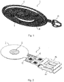


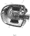
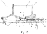
Classifications
-
- B—PERFORMING OPERATIONS; TRANSPORTING
- B05—SPRAYING OR ATOMISING IN GENERAL; APPLYING FLUENT MATERIALS TO SURFACES, IN GENERAL
- B05B—SPRAYING APPARATUS; ATOMISING APPARATUS; NOZZLES
- B05B17/00—Apparatus for spraying or atomising liquids or other fluent materials, not covered by the preceding groups
- B05B17/04—Apparatus for spraying or atomising liquids or other fluent materials, not covered by the preceding groups operating with special methods
- B05B17/06—Apparatus for spraying or atomising liquids or other fluent materials, not covered by the preceding groups operating with special methods using ultrasonic or other kinds of vibrations
- B05B17/0607—Apparatus for spraying or atomising liquids or other fluent materials, not covered by the preceding groups operating with special methods using ultrasonic or other kinds of vibrations generated by electrical means, e.g. piezoelectric transducers
- B05B17/0638—Apparatus for spraying or atomising liquids or other fluent materials, not covered by the preceding groups operating with special methods using ultrasonic or other kinds of vibrations generated by electrical means, e.g. piezoelectric transducers spray being produced by discharging the liquid or other fluent material through a plate comprising a plurality of orifices
- B05B17/0646—Vibrating plates, i.e. plates being directly subjected to the vibrations, e.g. having a piezoelectric transducer attached thereto
-
- A—HUMAN NECESSITIES
- A61—MEDICAL OR VETERINARY SCIENCE; HYGIENE
- A61M—DEVICES FOR INTRODUCING MEDIA INTO, OR ONTO, THE BODY; DEVICES FOR TRANSDUCING BODY MEDIA OR FOR TAKING MEDIA FROM THE BODY; DEVICES FOR PRODUCING OR ENDING SLEEP OR STUPOR
- A61M11/00—Sprayers or atomisers specially adapted for therapeutic purposes
- A61M11/005—Sprayers or atomisers specially adapted for therapeutic purposes using ultrasonics
Definitions
- the invention relates to an aerosol generator with a vibratable element for generating an aerosol and to an aerosol delivery device comprising the aerosol generator.
- Aerosols for therapeutic purposes are generated and delivered to a desired location within a user's or patient's body with aerosol delivery devices.
- a fluid or liquid (i.e., medicament) to be aerosolised or nebulised is supplied to an aerosol generator of the aerosol delivery device, the fluid or liquid is aerosolised or nebulised by the aerosol generator and the resultant aerosol is supplied to the user or patient.
- the fluid or liquid may be aerosolised or nebulised in the aerosol generator by a vibratable element, such as a vibratable head.
- a vibratable element such as a vibratable head.
- the characteristics of the vibratable element of the aerosol generator are decisive for the quality of the generated aerosol and for the aerosol dosage accuracy.
- the vibratable element is also generally very sensitive. A misalignment of the vibratable element may negatively affect the oscillatory or vibrating motion of the element during aerosol generation and therefore compromise the quality of the generated aerosol and the dosage accuracy.
- DE 10 2005 006 375 A1 An aerosol generator of this vibratable element type is disclosed in DE 10 2005 006 375 A1 .
- DE 10 2005 006 375 A1 discloses an aerosol generator for inhalation therapy devices, in which an oscillatable assembly, consisting of at least a membrane and an oscillation generator, is mounted in an encapsulating means by means of a flexible passage contacting the oscillatable assembly.
- the flexible passage comprises two flexible sealing lips which contact the oscillatable assembly from two opposing sides thereof.
- the flexible sealing lips exhibit the same degree of flexibility, there is a risk that the oscillatable assembly may move, e.g., tilt, during assembly and/or during operation of the aerosol generator. Such an undesired movement of the oscillatable assembly may adversely affect the oscillation or vibration thereof and thus impair the aerosol generation, both in terms of aerosol quality and aerosol dosage accuracy.
- WO 2011/083380 A1 discloses an apparatus for aerosol delivery of a substance, the apparatus having a mouthpiece, a chamber holding a substance, a flexible membrane with a plurality of apertures, and a vibrator for vibrating the flexible membrane to form a flow of aerosol droplets of the substance that are ejected through the apertures and to the mouthpiece.
- One object of the invention is to provide an aerosol generator which enables precise and reliable alignment of a vibratable element for generating an aerosol. Further, the invention aims to provide an aerosol delivery device comprising this aerosol generator. These goals are achieved by an aerosol generator with the technical features of claim 1 and an aerosol delivery device with the technical features of claim 11. Preferred embodiments of the invention follow from the dependent claims.
- the invention provides an aerosol generator comprising a housing or casing, having a first holding member or support member and a second holding member or support member, and a vibratable or oscillatable element, such as a vibratable or oscillatable head, for generating an aerosol.
- the vibratable element is at least partially accommodated or received in the housing.
- the vibratable element is contacted, e.g., touched or abutted, by the first and second holding or support members and held between the first and second holding or support members.
- the first holding or support member is less flexible, elastic and/or resilient than the second holding or support member.
- the first holding or support member comprises a plurality of protrusions in contact with the vibratable element.
- the first holding member has a lower degree of flexibility, elasticity and/or resilience than the second holding member.
- the first holding member is thus more rigid and/or stiff than the second holding member.
- the first holding member can serve as a support, bearing, rest or abutment for supporting the vibratable element in a stable and reliable manner during assembly and operation of the aerosol generator.
- the alignment or orientation of the vibratable element relative to the housing can be precisely controlled during assembly of the aerosol generator, e.g., by resting the element on the first holding member, and reliably maintained throughout the assembly process and during operation of the aerosol generator. In this way, a high aerosol quality and a high aerosol dosage accuracy can be achieved.
- the vibratable element may be held, i.e., held in its position relative to the housing, by the first and second holding members, in particular, held by the first holding member from a first side of the element and held by the second holding member from a second side of the element.
- the first side may be opposite to the second side.
- the first holding member may be disposed or arranged substantially below the second holding member in operation of the aerosol generator, i.e., when the aerosol generator is held in its operational position, or vice versa.
- the first holding member may be disposed or arranged substantially below the vibratable element and the second holding member may be disposed or arranged substantially above the vibratable element in operation of the aerosol generator, i.e., when the aerosol generator is held in its operational position, or vice versa.
- the vibratable element may be pressed or pushed by the first holding member and/or the second holding member.
- the vibratable element may be pressed or pushed by the second holding member against the first holding member, e.g., by an elastic force, resilient force or spring force of the second holding member.
- the first holding member and/or the second holding member may be configured to hold the vibratable element in its position relative to the housing in one, two or more directions, e.g., in two directions which are orthogonal or perpendicular to each other. In this way, the positioning accuracy of the vibratable element in the housing can be further improved.
- the first holding member may be substantially rigid. In this way, a particularly high degree of positioning accuracy of the vibratable element in, i.e., relative to, the housing can be achieved. Further, it has been found by the present inventors that a substantially rigid first holding member does not adversely affect the vibration or oscillation behaviour or characteristics of the vibratable element.
- the first holding member may be made of a substantially rigid material, such as hard plastic, glass fibre, crystal ball, metal, ceramic, colour pigmentation, as well as a combination thereof, like blue or green polypropylene with 20% crystal ball fraction (e.g. Piolen® P GK20A110), or the like.
- the substantially rigid material of the first holding member reduces the absorption of the vibration or oscillation and enhances the functionality of the vibratable element.
- the second holding member may be substantially flexible, elastic and/or resilient.
- the second holding member may be configured to apply a resilient force, an elastic force and/or a spring force to the vibratable element, pressing or pushing the element against the first holding member. In this way, the vibratable element can be held in place, i.e., in its position relative to the housing, in a particularly reliable manner.
- the second holding member may be made of a substantially flexible material, e.g., soft plastic or the like, such as a silicone, rubber, elastomer, thermoplastic elastomer (TPE), colour pigmentation, as well as a combination thereof, like blue thermoplastic elastomer (e.g. Thermolast K HTF 2147/17, blue) or the like.
- a substantially flexible material e.g., soft plastic or the like, such as a silicone, rubber, elastomer, thermoplastic elastomer (TPE), colour pigmentation, as well as a combination thereof, like blue thermoplastic elastomer (e.g. Thermolast K HTF 2147/17, blue) or the like.
- the first and/or second holding member may be coated, caved and/or laminated with a further material or component even flexible or rigid, preferably with a relatively small thickness, so that it will not influence the functionality of the first and/or second holding member.
- the first holding member comprises a plurality of protrusions, e.g., ribs, ridges, base saddle, place restrictions, (stop) ridge or the like, in contact with the vibratable element.
- the vibratable element may be contacted by the first holding member only at or through the plurality of protrusions.
- the protrusions e.g., the ribs, ridges or the like, may be made from a substantially rigid material, such as hard plastic, glass fibre, metal, ceramic, a combination thereof or the like.
- the protrusions may be coated, covered or encased with a substantially flexible material, e.g., a soft plastic, such as silicone, rubber, elastomer, thermoplastic elastomer (TPE), a combination thereof or the like.
- a substantially flexible material e.g., a soft plastic, such as silicone, rubber, elastomer, thermoplastic elastomer (TPE), a combination thereof or the like.
- the vibratable element may comprise a vibratable membrane.
- the vibratable membrane may be configured to generate an aerosol, i.e., to aerosolise or nebulise a fluid or liquid supplied to the membrane.
- the vibratable membrane may have a plurality of holes or openings. Fluid or liquid abutting the membrane on one side thereof may be conveyed through these holes or openings in the vibrating membrane to the other side thereof and emitted on this side as an aerosol.
- the vibratable element may comprise a vibrator which is configured to vibrate the vibratable element.
- the vibrator may be configured to vibrate the vibratable membrane.
- the vibrator may comprise a piezoelectric element which is configured to vibrate or oscillate the vibratable element, e.g., the vibratable membrane or oscillatable assembly.
- the vibrator may be attached, e.g., adhered, for example, using an adhesive, such as a glue, directly to the vibratable membrane or directly to a support member supporting the vibratable membrane.
- the support member may be formed integrally with the vibratable membrane.
- the aerosol generator may be or form part of a nebuliser, such as a vibrating membrane nebuliser, e.g., an electronic vibrating membrane nebuliser, an atomiser or the like.
- the aerosol generator may be an electronic nebuliser, e.g., a piezoelectrically driven nebuliser, i.e., a nebuliser driven by a piezoelectric element.
- the piezoelectric element may form part of the vibrator and be arranged for vibrating or oscillating the vibratable element, e.g., the vibratable membrane or oscillatable assembly.
- the housing may comprise a fluid or liquid reservoir for receiving a fluid or liquid to be aerosolised or nebulised.
- the fluid or liquid reservoir may be arranged for directly receiving the fluid or liquid to be aerosolised.
- the fluid or liquid reservoir may be configured as or have a fluid or liquid chamber or container into which a fluid or liquid can be directly filled.
- the fluid or liquid reservoir may be arranged for receiving a fluid or liquid containing vessel.
- the fluid or liquid reservoir may be designed so that it does not directly receive the fluid or liquid but rather has an opening element, such as a thorn, a spike, a hollow needle or the like, arranged on its inside that opens the fluid containing vessel, e.g., a vial, a blister, an ampoule, a container, a canister, a reservoir, a cartridge, a pot, a tank, a pen, a storage, a syringe or the like, inserted therein.
- an opening element such as a thorn, a spike, a hollow needle or the like
- the fluid or liquid reservoir may be arranged in fluid communication with the vibratable element, e.g., the vibratable membrane.
- the fluid may be delivered via gravitational force to the vibratable element.
- a fluid or liquid to be nebulised or aerosolised by the aerosol generator may be a fluid or liquid for the generation of a pharmaceutical aerosol for the delivery of an active compound.
- An active compound is a natural, biotechnology-derived or synthetic compound or mixture of compounds useful for the diagnosis, prevention, management or treatment of a disease, condition or symptom of an animal, in particular a human.
- active compounds include, for example, active ingredient, active pharmaceutical ingredient, drug substance, diagnostic material, drug, medicament and the like.
- the fluid could be of a liquid, solution, suspension, colloidal mixture or liposomal formulation form and can be prepared, mixed or opened before or during the application.
- the active compound comprised in the fluid to be nebulised or aerosolised by the aerosol generator may be a drug substance or a medicament which is useful for the prevention, management, diagnosis or treatment of any disease, symptom or condition affecting the body cavities, the abdomen, the eyes, the intestine, the stomach, the nose, the sinuses, the osteomeatal complex, the mouth, the trachea, the lungs, the bronchia, the bronchioles, the alveoli and/or the respiratory tract.
- active compounds which may be useful for serving one of the purposes named previously and that may be used together with the present invention, are, for example, substances selected from the group consisting of anti-inflammatory compounds, anti-infective agents, antiseptics, prostaglandins, endothelin receptor agonists, phosphodiesterase inhibitors, beta-2-sympathicomimetics, decongestants, vasoconstrictors, anticholinergics, immunomodulators, mucolytics, anti-allergic drugs, antihistaminics, mast-cell stabilizing agents, tumor growth inhibitory agents, wound healing agents, local anaesthetics, antioxidants, oligonucleotides, peptides, proteins, vaccines, vitamins, plant extracts, cholinesterase inhibitors, vasoactive intestinal peptide, serotonin receptor antagonists, and heparins, glucocorticoids, anti-allergic drugs, antioxidants, vitamins, leucotriene antagonists, anti-infective agents, antibiotics
- anti-inflammatory compounds examples include glucocorticoids and non-steroidal anti-inflammatory agents such as betamethasone, beclomethasone, budesonide, ciclesonide, dexamethasone, desoxymethasone, fluocinolone acetonide, fluocinonide, flunisolide, fluticasone, icomethasone, rofleponide, triamcinolone acetonide, fluocortin butyl, hydrocortisone, hydroxycortisone-17-butyrate, prednicarbate, 6-methylprednisolone aceponate, mometasone furoate, dehydroepiandrosterone-sulfate (DHEAS), elastane, prostaglandin, leukotriene, bradykinin antagonists, non-steroidal anti-inflammatory drugs (NSAIDs), such as ibuprofen including any pharmaceutically acceptable salts, esters, isomers, stereoisomers,
- anti-infective agents whose class or therapeutic category is herein understood as comprising compounds which are effective against bacterial, fungal, and viral infections, i.e. encompassing the classes of antimicrobials, antibiotics, antifungals, antiseptics, and antivirals, are
- Examples of potentially useful mucolytics are DNase (including dornase alpha), P2Y2-agonists (denufosol), drugs affecting chloride and sodium permeation, such as N-(3,5-Diamino-6-chloropyrazine-2-carbony)-N'- ⁇ 4-[4-(2,3-dihydroxypropoxy)-phenyl]butyl ⁇ guanidine methanesulfonate (PARION 552-02), heparinoids, guaifenesin, acetylcysteine, carbocysteine, ambroxol, bromhexine, tyloxapol, lecithins, myrtol, surfactants, surfactant proteins, recombinant surfactant proteins and/or any other chemical or physical forms of active compounds comprising the respective active moieties.
- DNase including dornase alpha
- P2Y2-agonists denufosol
- vasoconstrictors and decongestants which may be useful to reduce the swelling of the mucosa are phenylephrine, naphazoline, tramazoline, tetryzoline, oxymetazoline, fenoxazoline, xylometazoline, epinephrine, isoprenaline, hexoprenaline, and ephedrine.
- Examples of potentially useful local anaesthetic agents include benzocaine, tetracaine, procaine, lidocaine and bupivacaine.
- antiallergic agents examples include the afore-mentioned glucocorticoids, cromolyn sodium, nedocromil, cetrizin, loratidin, montelukast, roflumilast, ziluton, omalizumab, heparinoids and other antihistamins, including azelastine, cetirizin, desloratadin, ebastin, fexofenadin, levocetirizin, loratadin.
- anticholinergic agents examples include ipratropium bromide, tiotropium bromide, oxitropium bromide, glycopyrrolate.
- beta-2-sympathicomimetic agents examples include salbutamol, fenoterol, formoterol, indacaterol, isoproterenol, metaproterenol, salmeterol, terbutaline, clenbuterol, isoetarine, pirbuterol, procaterol, ritodrine.
- xanthine derived agents examples include theophylline, theobromine, caffeine.
- Antisense oligonucleotides are short synthetic strands of DNA (or analogs) that are complimentary or antisense to a target sequence (DNA, RNA) designed to halt a biological event, such as transcription, translation or splicing.
- a biological event such as transcription, translation or splicing.
- the resulting inhibition of gene expression makes oligonucleotides dependent on their composition useful for the treatment of many diseases and various compounds are currently clinically evaluated, such as ALN-RSV01 to treat the respiratory syncytical virus, AVE-7279 to treat asthma and allergies, TPI-ASM8 to treat allergic asthma, 1018-ISS to treat cancer.
- Examples of potentially useful peptides and proteins include antibodies against toxins produced by microorganisms, antimicrobial peptides such as cecropins, defensins, thionins, and cathelicidins.
- antibodies examples include immunoglobulins (e.g. Ig, IgG, IgE, IgM, IgA) and/or any other chemical or physical forms of active compounds comprising the respective active moieties thereof.
- immunoglobulins e.g. Ig, IgG, IgE, IgM, IgA
- any other chemical or physical forms of active compounds comprising the respective active moieties thereof.
- the second holding member may be provided on, e.g., attached or secured to, the fluid or liquid reservoir.
- the relative alignment or orientation between the vibratable element and the fluid reservoir can be established and maintained in a particularly precise and reliable manner.
- the flow of fluid or liquid from the fluid or liquid reservoir to the vibratable element can be accurately and reliably controlled, thus further enhancing aerosol quality and dosage accuracy.
- the second holding member may be configured to guide the fluid or liquid from the fluid or liquid reservoir to the vibratable element, e.g., the vibratable membrane and/or vibratable head, e.g. via gravitational force.
- the vibratable element e.g., the vibratable membrane and/or vibratable head
- gravitational force e.g. via gravitational force.
- the vibratable element may comprise one or more electrical contacts, e.g., plugs, connectors, jacks, clips, cinches or the like, for connection to a control, e.g., an external control.
- a control e.g., an external control.
- the control may be any type of control, e.g., a control unit, a control element, a control circuit or the like.
- the control may be capable of operating the vibrator of the aerosol generator.
- the control may be connectable through the one or more electrical contacts to the vibrator, e.g., to a power supply element of the vibrator.
- the one or more electrical contacts may be formed from a metal sheet, such as a stainless steel sheet, e.g., punched out from the metal sheet.
- the one or more electrical contacts may be bent, e.g., after punching them out, for example, bent into a curved and/or cambered shape.
- the vibratable element may comprise a plurality of electrical contacts for connection to the control and all of the plurality of electrical contacts may have the same configuration.
- the one or more electrical contacts may be connected to the remainder of the vibratable element, e.g., to a front portion thereof and/or the vibrator, through a strip conductor, e.g., a flexible strip conductor, such as a printed circuit board track or a strip line.
- the strip conductor may have contact pads, e.g., gold contact pads, for connection with the one or more electrical contacts and/or the remainder of the vibratable element.
- the one or more electrical contacts and/or the remainder of the vibratable element may be secured to and/or electrically connected with the contact pads of the strip conductor by brazing, soldering, welding, resistance welding, HF resistance welding, electrically conductive coating, electrically conductive gluing or the like.
- a portion of the vibratable element comprising one or more or all of the contacting areas, in which the one or more electrical contacts and/or the remainder of the vibratable element are connected, e.g. welded, to the strip conductor, may be covered or encapsulated with a cover member.
- the cover member may electrically insulate the one or more contacting areas.
- the cover member may be made of a plastic and/or insulating material.
- the cover member may be applied to the one or more contacting areas, for example, by injection moulding or a hot-melting adhesive process.
- the invention provides an aerosol delivery device comprising the aerosol generator.
- the aerosol delivery device may be an aerosol generation device, an aerosol inhalation device, a medical aerosol device, an aerosol diagnostic device, an aerosol prophylactic device, an aerosol therapeutic device, an aerosol humidification device, an aerosol therapy device or the like.
- the aerosol delivery device may comprise a control as defined above.
- the aerosol delivery device may comprise an aerosol cavity or an aerosol chamber for receiving an aerosol generated by the aerosol generator.
- the aerosol delivery device may comprise a mouthpiece and/or a nosepiece and/or nasal prongs and/or an endotracheal tube and/or a ventilator tube system and/or a face mask.
- the generated aerosol may be supplied from the aerosol cavity or chamber to a user or patient through the mouthpiece and/or nosepiece and/or nasal prongs and/or endotracheal tube and/or ventilator tube system and/or face mask.
- the present disclosure provides a fluid or liquid reservoir for an aerosol generator or an aerosol delivery device, the fluid or liquid reservoir comprising a fluid or liquid chamber for receiving a fluid or liquid to be aerosolised or nebulised.
- the fluid or liquid chamber comprises an opening for guiding the fluid or liquid outside the fluid or liquid chamber, e.g., to a vibratable element, a vibratable head, a vibratable membrane, or an oscillatable assembly of an aerosol generator.
- the fluid or liquid chamber, in particular, the opening may include a flexible component and/or flexible material, such as a seal, sealing lip, sealing ring, lip seal, joint ring, or seal gasket.
- the aerosol delivery device may comprise an aerosol generator with a vibratable element, e.g., the aerosol generator defined above, wherein the vibratable element may be arranged in horizontal alignment or orientation, i.e., so that the vibratable element lies in the horizontal plane when the fluid or liquid reservoir is in the upright, i.e., vertical position.
- a vibratable element e.g., the aerosol generator defined above
- the vibratable element may be arranged in horizontal alignment or orientation, i.e., so that the vibratable element lies in the horizontal plane when the fluid or liquid reservoir is in the upright, i.e., vertical position.
- Fig. 1 shows a schematic perspective bottom view of a front portion 2 of a vibratable element 4 (see Fig. 2 ) of an aerosol generator 1 (see Fig. 9 ) according to a currently preferred embodiment of the present invention.
- the front portion 2 of the vibratable element 4 comprises a support member 6, a vibratable membrane 8 with a plurality of openings or holes (not shown), an annular piezoelement 10 and a connection portion 12.
- the vibratable membrane 8 is integrally formed with the support member 6.
- the vibratable membrane 8 and the support member 6 are made from a metal, such as stainless steel.
- the piezoelement 10 is attached, e.g., adhered, for example, using an adhesive, such as a glue, directly to the support member 6.
- the piezoelement 10 serves as a vibrator for vibrating the vibratable membrane 8.
- the vibratable element 4 further comprises a pair of electrical contacts 14, 14', e.g., plugs, for connection to a control (not shown).
- the electrical contacts 14, 14' are punched out from a stainless steel sheet and subsequently bent, i.e., bent into the shape shown in Fig. 2 .
- Both electrical contacts 14, 14' may have the same configuration, but the first contact 14 is rotated by 180° around its longitudinal axis relative to the second contact 14' .
- the electrical contacts 14, 14' are connected to the connection member 12 and the piezoelement 10 through a flexible strip conductor 16, such as a printed circuit board track or a strip line.
- the flexible strip conductor 16 has gold contact pads for connection with the electrical contacts 14, 14' and the connection member 12.
- the electrical contacts 14, 14' and the connection member 12 are secured to and electrically connected with the respective gold contact pads of the strip conductor 16 by welding, especially by resistance stud welding.
- the strip conductor 16 is secured to and electrically connected with the piezoelement 10, as is shown in Fig. 3 .
- the portion of the vibratable element 4 comprising the contacting or welding areas where the connection member 12 and the two electrical contacts 14, 14' are welded to the strip conductor 16 is encapsulated with a cover member 18, as is shown in Figs. 4 and 5 , and thus electrically insulated.
- the cover member 18 is made of a plastic material.
- the vibratable element 4 can be manufactured in a simple, reliable and cost efficient way, using a minimum amount of parts.
- the aerosol generator 1 of the currently preferred embodiment further comprises a housing having a lower housing part 20 (see Fig. 6 ) and a fluid reservoir 22 (see Figs. 9 and 10 ).
- the lower housing part 20 comprises three protrusions 24, 24', 24", i.e., ribs, for supporting and holding the front portion 2 of the vibratable element 4.
- the protrusions 24, 24', 24'' are made from a rigid material, such as hard plastic, metal, ceramic or the like.
- the protrusions 24, 24', 24'' have a stepped upper surface, supporting the front portion 2 of the vibratable element 4 in orthogonal directions, namely in the axial direction, i.e., from below, and in the radial direction thereof.
- the three protrusions 24, 24', 24'' form the first holding member of the housing of the aerosol generator 1.
- the lower housing part 20 further comprises a pair of valve flaps 26, 26'.
- the valve flaps 26, 26' are hingedly attached to the remainder of the lower housing part 20 so as to allow pivoting thereof towards and away from the protrusions 24, 24', 24''.
- the valve flaps 26, 26' open, so as to allow ambient air to flow into the aerosol generator 1.
- an aerosol generated by the aerosol generator 1 can be supplied to the user or patient together with the ambient air introduced via a direct flow path into the generator 1.
- the valve flaps 26, 26' close, thus reliably avoiding any undesired transport of aerosol outside the aerosol generator 1. Hence, any loss of aerosol can be reliably prevented.
- the lower housing part 20 may be formed by moulding, for example, by injection moulding.
- the protrusions 24, 24', 24'' may be coated, covered or encased with a flexible material, e.g., a soft plastic, such as a thermoplastic elastomer.
- the vibratable element 4 is received in the lower housing part 20 with the front portion 2 resting on the protrusions 24, 24', 24'', as is shown in Figs. 7 and 8 .
- the protrusions 24, 24', 24'' inhibit any movement of the front portion 2 of the vibratable element 4 in radial and downward axial directions.
- the front portion 2 of the vibratable element 4 is first placed on the rigid protrusions 24, 24', 24''.
- These protrusions 24, 24', 24'' provide stable support to the front portion 2, reliably preventing any undesired movement thereof, both in the further assembly process and during operation of the aerosol generator 1.
- the housing of the aerosol generator 1 further comprises the fluid reservoir 22, as is shown in Figs. 9 and 10 .
- the fluid reservoir 22 is placed on top of the lower housing part 20, thereby completing the housing of the aerosol generator 1.
- the fluid reservoir 22 may be formed by moulding, for example, by injection moulding.
- the fluid reservoir 22 comprises a fluid chamber 28 for receiving a fluid (not shown) to be aerosolised.
- the fluid chamber 28 comprises an opening 32 for guiding the fluid outside the fluid chamber 28, i.e., towards the vibratable membrane 8.
- the fluid reservoir 22 is arranged so that its axial direction is substantially perpendicular to the plane of the front portion 2 of the vibratable element 4.
- the fluid reservoir 22 further comprises a sealing member 38 which is secured to the fluid reservoir 22 in a position below the opening 32 of the fluid chamber 28 (see Fig. 10 ).
- the sealing member 38 is made of a flexible, elastic and resilient material, e.g., a soft plastic, such as a thermoplastic elastomer, silicone, rubber, o-ring seal or the like.
- the sealing member 38 is configured to guide the fluid from the opening 32 of the fluid chamber 28 of the fluid reservoir 22 to the vibratable membrane 8 of the vibratable element 4 by gravitational force.
- the sealing member 38 contacts the upper surface of the front portion 2 of the vibratable element 4.
- the sealing member 38 of the fluid reservoir 22 thus forms the second holding member of the housing.
- the resilient force of the sealing member 38 presses the front portion 2 of the vibratable element 4 against the protrusions 24, 24' 24'' of the lower housing part 20.
- the front portion 2 is thus securely held between the protrusions 24, 24', 24'' and the sealing member 38 in the axial and radial directions. Any undesired movement of the vibratable element 4 during assembly and operation of the aerosol generator 1 is thus reliably prevented.
- a predetermined amount of fluid e.g., a liquid
- a predetermined amount of fluid is filled into the fluid chamber 28 of the fluid reservoir 22.
- the upper portion of the fluid chamber 28 is closed, for example, with a cap, such as a screw cap (not shown).
- a portion of the fluid flows through the opening 32 of the fluid chamber 28 and the sealing member 38, so as to abut the vibratable membrane 8 of the vibratable element 4.
- An activation signal of the control (not shown) is supplied to the piezoelement 10 of the front portion 2 of the vibratable element 4 via the electrical contacts 14, 14' and the strip conductor 16, causing the membrane 8 to vibrate.
- the fluid abutting the membrane 18 is conveyed through the holes or openings (not shown) in the vibrating membrane 8 and thereby aerosolised into an aerosol cavity or chamber (not shown) of an aerosol delivery device (not shown) arranged below the vibrating membrane 8.
- the aerosol thus provided in the aerosol cavity or chamber can be inhaled by a user or patient through a mouthpiece, nosepiece, nasal prongs, endotracheal tube, ventilator tube system, and/or face mask (not shown) of the aerosol delivery device.
- valve flaps 26, 26' of the lower housing part 20 open during an inhalation manoeuvre of the user or patient, so as to allow ambient air to flow via a flow path directly into the aerosol delivery device.
- the aerosol generated by the aerosol generator 1 is supplied to the user or patient together with the air introduced by the valve flaps 26, 26'.
- the valve flaps 26, 26' close, thus reliably avoiding any undesired transport of the generated aerosol outside the aerosol delivery device. Therefore, any loss of aerosol can be reliably prevented.
Landscapes
- Health & Medical Sciences (AREA)
- Engineering & Computer Science (AREA)
- Anesthesiology (AREA)
- Biomedical Technology (AREA)
- Heart & Thoracic Surgery (AREA)
- Hematology (AREA)
- Life Sciences & Earth Sciences (AREA)
- Animal Behavior & Ethology (AREA)
- General Health & Medical Sciences (AREA)
- Public Health (AREA)
- Veterinary Medicine (AREA)
- Medicinal Preparation (AREA)
Claims (11)
- Générateur d'aérosol (1) comprenant- un boîtier (20, 22) comprenant un premier élément de maintien (24, 24', 24") et un second élément de maintien (38), et- un élément pouvant vibrer (4) pour la production d'un aérosol,
dans lequel- l'élément pouvant vibrer (4) est au moins en partie logé dans le boîtier (20, 22),- l'élément pouvant vibrer (2) est en contact avec les premier et second éléments de maintien (24, 24', 24" ; 38) et maintenu entre ceux-ci, et- le premier élément de maintien (24, 24', 24") est moins flexible que le second élément de maintien (38),caractérisé en ce que
le premier élément de maintien (24, 24', 24") comprend une pluralité de saillies en contact avec l'élément pouvant vibrer (4). - Générateur d'aérosol (1) selon la revendication 1, dans lequel le premier élément de maintien (24, 24', 24") est sensiblement rigide.
- Générateur d'aérosol (1) selon la revendication 1 ou 2, dans lequel le second élément de maintien (38) est sensiblement flexible.
- Générateur d'aérosol (1) selon l'une quelconque des revendications précédentes, dans lequel les saillies sont formées d'un matériau sensiblement rigide.
- Générateur d'aérosol (1) selon l'une quelconque des revendications précédentes, dans lequel l'élément pouvant vibrer (4) comprend une membrane pouvant vibrer (8).
- Générateur d'aérosol (1) selon l'une quelconque des revendications précédentes, dans lequel l'élément pouvant vibrer (4) comprend un vibreur (10) qui est configuré pour faire vibrer l'élément pouvant vibrer (4).
- Générateur d'aérosol (1) selon l'une quelconque des revendications précédentes, dans lequel le boîtier (20, 22) comprend un réservoir de fluide (22) pour recevoir un fluide (30) à mettre en suspension.
- Générateur d'aérosol (1) selon la revendication 7, dans lequel le second élément de maintien (38) est prévu sur le réservoir de fluide (22).
- Générateur d'aérosol (1) selon la revendication 7 ou 8, dans lequel le second élément de maintien (38) est configuré pour guider le fluide (30) entre le réservoir de fluide (22) et l'élément pouvant vibrer (4).
- Générateur d'aérosol (1) selon l'une quelconque des revendications précédentes, dans lequel l'élément pouvant vibrer (4) comprend un ou plusieurs contacts électriques (14, 14') pour la connexion à une commande.
- Dispositif de distribution d'aérosol comprenant le générateur d'aérosol (1) selon l'une quelconque des revendications précédentes.
Priority Applications (1)
| Application Number | Priority Date | Filing Date | Title |
|---|---|---|---|
| EP19190981.1A EP3586976B1 (fr) | 2014-06-20 | 2015-06-18 | Générateur d'aérosol et dispositif de distribution d'aérosol comprenant le générateur |
Applications Claiming Priority (2)
| Application Number | Priority Date | Filing Date | Title |
|---|---|---|---|
| EP14173249.5A EP2957349A1 (fr) | 2014-06-20 | 2014-06-20 | Générateur d'aérosol et dispositif de distribution d'aérosol comprenant le générateur |
| PCT/EP2015/063707 WO2015193432A1 (fr) | 2014-06-20 | 2015-06-18 | Générateur d'aérosol et dispositif de distribution d'aérosol comprenant le générateur d'aérosol |
Related Child Applications (2)
| Application Number | Title | Priority Date | Filing Date |
|---|---|---|---|
| EP19190981.1A Division EP3586976B1 (fr) | 2014-06-20 | 2015-06-18 | Générateur d'aérosol et dispositif de distribution d'aérosol comprenant le générateur |
| EP19190981.1A Division-Into EP3586976B1 (fr) | 2014-06-20 | 2015-06-18 | Générateur d'aérosol et dispositif de distribution d'aérosol comprenant le générateur |
Publications (2)
| Publication Number | Publication Date |
|---|---|
| EP3157683A1 EP3157683A1 (fr) | 2017-04-26 |
| EP3157683B1 true EP3157683B1 (fr) | 2019-09-25 |
Family
ID=51167575
Family Applications (3)
| Application Number | Title | Priority Date | Filing Date |
|---|---|---|---|
| EP14173249.5A Withdrawn EP2957349A1 (fr) | 2014-06-20 | 2014-06-20 | Générateur d'aérosol et dispositif de distribution d'aérosol comprenant le générateur |
| EP15733654.6A Active EP3157683B1 (fr) | 2014-06-20 | 2015-06-18 | Générateur d'aérosol et dispositif de distribution d'aérosol comprenant le générateur |
| EP19190981.1A Active EP3586976B1 (fr) | 2014-06-20 | 2015-06-18 | Générateur d'aérosol et dispositif de distribution d'aérosol comprenant le générateur |
Family Applications Before (1)
| Application Number | Title | Priority Date | Filing Date |
|---|---|---|---|
| EP14173249.5A Withdrawn EP2957349A1 (fr) | 2014-06-20 | 2014-06-20 | Générateur d'aérosol et dispositif de distribution d'aérosol comprenant le générateur |
Family Applications After (1)
| Application Number | Title | Priority Date | Filing Date |
|---|---|---|---|
| EP19190981.1A Active EP3586976B1 (fr) | 2014-06-20 | 2015-06-18 | Générateur d'aérosol et dispositif de distribution d'aérosol comprenant le générateur |
Country Status (6)
| Country | Link |
|---|---|
| US (1) | US10758929B2 (fr) |
| EP (3) | EP2957349A1 (fr) |
| JP (1) | JP2017521148A (fr) |
| CN (1) | CN107106790B (fr) |
| ES (1) | ES2870573T3 (fr) |
| WO (1) | WO2015193432A1 (fr) |
Cited By (1)
| Publication number | Priority date | Publication date | Assignee | Title |
|---|---|---|---|---|
| EP4230064A1 (fr) * | 2021-12-21 | 2023-08-23 | Shenzhen Moore Vaporization Health & Medical Technology Co., Ltd. | Ensemble d'atomisation microporeux et dispositif d'atomisation ultrasonore |
Families Citing this family (19)
| Publication number | Priority date | Publication date | Assignee | Title |
|---|---|---|---|---|
| US12042809B2 (en) * | 2015-11-02 | 2024-07-23 | Altria Client Services Llc | Aerosol-generating system comprising a vibratable element |
| TWI701056B (zh) * | 2016-07-19 | 2020-08-11 | 微邦科技股份有限公司 | 微霧化裝置 |
| CN111148579B (zh) * | 2017-12-14 | 2021-10-01 | 斯坦福设备有限公司 | 气雾剂产生器孔板到支撑件的安装 |
| EP3556475A1 (fr) | 2018-04-20 | 2019-10-23 | PARI GmbH Spezialisten für effektive Inhalation | Dispositif de commande pour générateur d'aérosols |
| CN110394268B (zh) * | 2018-04-25 | 2021-07-02 | 微邦科技股份有限公司 | 微雾生成装置及微雾产生器 |
| CN110393837B (zh) * | 2018-04-25 | 2022-03-29 | 微邦科技股份有限公司 | 微雾产生器及雾化模块 |
| EP3603617A1 (fr) * | 2018-07-30 | 2020-02-05 | Sterna Biologicals GmbH & Co. KG | Dispositif générateur d'aérosol destiné à l'administration par inhalation d'une composition contenant une molécule antisens |
| EP3894091B1 (fr) | 2018-12-14 | 2023-08-16 | PARI Pharma GmbH | Têtes de vibrations à base de couplage inductif pour un générateur d'aérosol |
| US10933203B2 (en) * | 2018-12-19 | 2021-03-02 | L'oreal | Adjustable misting arrays |
| EP3954240B1 (fr) * | 2019-04-18 | 2024-05-08 | China Tobacco Hunan Industrial Co., Ltd. | Noyau d'atomisation de cigarette électronique et atomiseur de cigarette électronique |
| WO2021198116A1 (fr) | 2020-04-01 | 2021-10-07 | UNION therapeutics A/S | Formulation |
| US11045434B1 (en) | 2020-04-01 | 2021-06-29 | UNION therapeutics A/S | Niclosamide formulations for treating disease |
| US20230147683A1 (en) | 2020-04-01 | 2023-05-11 | UNION therapeutics A/S | Treatment |
| US20220031970A1 (en) * | 2020-07-31 | 2022-02-03 | Bn Intellectual Properties, Inc. | Capsule retaining system |
| CA3197653A1 (fr) | 2020-10-12 | 2022-04-21 | Vectura Delivery Devices Limited | Generateur d'aerosol pour un dispositif d'inhalation |
| US20230390507A1 (en) | 2020-10-16 | 2023-12-07 | Vectura Delivery Devices Limited | Method for detecting the presence of liquid in a vibrating membrane nebulizer |
| EP4015094A1 (fr) | 2020-12-16 | 2022-06-22 | Vectura Delivery Devices Limited | Nébuliseur à membrane vibrante |
| CA3201509A1 (fr) | 2020-12-16 | 2022-06-23 | Vectura Delivery Devices Limited | Detection de la presence de liquide dans un nebuliseur a membrane vibrante |
| EP4424429A1 (fr) * | 2023-03-03 | 2024-09-04 | PARI Pharma GmbH | Unité de membrane pour un générateur d'aérosol |
Family Cites Families (21)
| Publication number | Priority date | Publication date | Assignee | Title |
|---|---|---|---|---|
| US4420706A (en) * | 1979-01-15 | 1983-12-13 | Molex Incorporated | Connector assembly for a piezoelectric transducer |
| US4550325A (en) * | 1984-12-26 | 1985-10-29 | Polaroid Corporation | Drop dispensing device |
| JPH0520458Y2 (fr) | 1988-10-31 | 1993-05-27 | ||
| US5021701A (en) * | 1988-10-20 | 1991-06-04 | Tdk Corporation | Piezoelectric vibrator mounting system for a nebulizer |
| US5306981A (en) * | 1992-11-19 | 1994-04-26 | Humonics International Inc. | Piezoelectric vibrator assembly |
| IT229674Y1 (it) * | 1993-02-26 | 1999-01-29 | Alcatel Dial Face Spa | Capsula piezoceramica per apparecchi telefonici |
| US6366678B1 (en) * | 1999-01-07 | 2002-04-02 | Sarnoff Corporation | Microphone assembly for hearing aid with JFET flip-chip buffer |
| US6948491B2 (en) * | 2001-03-20 | 2005-09-27 | Aerogen, Inc. | Convertible fluid feed system with comformable reservoir and methods |
| MXPA02010884A (es) | 2000-05-05 | 2003-03-27 | Aerogen Ireland Ltd | Aparato y metodo para el suministro de medicamentos al sistema respiratorio. |
| US6446880B1 (en) * | 2000-08-02 | 2002-09-10 | S.C. Johnson & Son, Inc. | Replaceable reservoir for an atomizing apparatus |
| US6732944B2 (en) * | 2001-05-02 | 2004-05-11 | Aerogen, Inc. | Base isolated nebulizing device and methods |
| US6978779B2 (en) * | 2002-04-19 | 2005-12-27 | Instrumentarium Corp. | Vibrating element liquid discharging apparatus having gas pressure sensing |
| US6843430B2 (en) * | 2002-05-24 | 2005-01-18 | S. C. Johnson & Son, Inc. | Low leakage liquid atomization device |
| DE10257381B4 (de) * | 2002-12-09 | 2006-09-14 | Pari GmbH Spezialisten für effektive Inhalation | Inhalationstherapievorrichtung |
| DE102005006375B4 (de) | 2005-02-11 | 2007-10-11 | Pari GmbH Spezialisten für effektive Inhalation | Aerosolerzeugungsvorrichtung für Inhalationstherapiegeräte |
| DE102005006374B3 (de) * | 2005-02-11 | 2006-07-20 | Pari GmbH Spezialisten für effektive Inhalation | Aerosolerzeugungsvorrichtung und Inhalationstherapiegerät mit einer derartigen Vorrichtung |
| ES2514470T3 (es) * | 2005-05-25 | 2014-10-28 | Aerogen, Inc. | Sistemas y métodos de vibración |
| JP5759480B2 (ja) * | 2010-01-11 | 2015-08-05 | コーニンクレッカ フィリップス エヌ ヴェ | エアロゾル生成装置用の磁気カプリング |
| JP5504121B2 (ja) * | 2010-09-30 | 2014-05-28 | パナソニックヘルスケア株式会社 | 過酸化水素水の霧化装置 |
| WO2012043682A1 (fr) * | 2010-09-30 | 2012-04-05 | 三洋電機株式会社 | Dispositif d'atomisation de solution de peroxyde d'hydrogène, dispositif de production de substance de stérilisation, dispositif de production de gaz et isolateur |
| EP2708219A1 (fr) * | 2012-09-12 | 2014-03-19 | PARI Pharma GmbH | Élément d'ouverture pour ouvrir une ampoule dans un dispositif de génération d'aérosol et dispositif de génération d'aérosol comprenant l'élément d'ouverture |
-
2014
- 2014-06-20 EP EP14173249.5A patent/EP2957349A1/fr not_active Withdrawn
-
2015
- 2015-06-18 ES ES19190981T patent/ES2870573T3/es active Active
- 2015-06-18 EP EP15733654.6A patent/EP3157683B1/fr active Active
- 2015-06-18 US US15/320,368 patent/US10758929B2/en active Active
- 2015-06-18 JP JP2016574131A patent/JP2017521148A/ja active Pending
- 2015-06-18 EP EP19190981.1A patent/EP3586976B1/fr active Active
- 2015-06-18 CN CN201580041605.8A patent/CN107106790B/zh active Active
- 2015-06-18 WO PCT/EP2015/063707 patent/WO2015193432A1/fr active Application Filing
Non-Patent Citations (1)
| Title |
|---|
| None * |
Cited By (1)
| Publication number | Priority date | Publication date | Assignee | Title |
|---|---|---|---|---|
| EP4230064A1 (fr) * | 2021-12-21 | 2023-08-23 | Shenzhen Moore Vaporization Health & Medical Technology Co., Ltd. | Ensemble d'atomisation microporeux et dispositif d'atomisation ultrasonore |
Also Published As
| Publication number | Publication date |
|---|---|
| EP3586976A1 (fr) | 2020-01-01 |
| CN107106790A (zh) | 2017-08-29 |
| WO2015193432A1 (fr) | 2015-12-23 |
| US10758929B2 (en) | 2020-09-01 |
| CN107106790B (zh) | 2021-08-24 |
| US20180178240A1 (en) | 2018-06-28 |
| ES2870573T3 (es) | 2021-10-27 |
| EP3157683A1 (fr) | 2017-04-26 |
| EP3586976B1 (fr) | 2021-03-31 |
| JP2017521148A (ja) | 2017-08-03 |
| EP2957349A1 (fr) | 2015-12-23 |
Similar Documents
| Publication | Publication Date | Title |
|---|---|---|
| EP3157683B1 (fr) | Générateur d'aérosol et dispositif de distribution d'aérosol comprenant le générateur | |
| EP3183021B1 (fr) | Réservoir de fluide destiné à un générateur d'aérosol et générateur aérosol comprenant ledit réservoir | |
| CA2994491C (fr) | Procede de fabrication d'une tete susceptible de vibrer pour un generateur d'aerosol et tete susceptible de vibrer pour un generateur d'aerosol | |
| US20230119086A1 (en) | Aerosol delivery device and operating method for the aerosol delivery device | |
| EP2895136B1 (fr) | Élément d'ouverture pour ouvrir une ampoule dans un dispositif de génération d'aérosol et dispositif de génération d'aérosol comprenant l'élément d'ouverture | |
| EP3384947A1 (fr) | Dispositif de distribution de fluide | |
| EP3893971B1 (fr) | Dispositif d'administration d'aérosol et procédé de fonctionnement du dispositif d'administration d'aérosol | |
| EP3893970B1 (fr) | Dispositif d'administration d'aérosol et procédé pour faire fonctionner un dispositif d'administration d'aérosol |
Legal Events
| Date | Code | Title | Description |
|---|---|---|---|
| STAA | Information on the status of an ep patent application or granted ep patent |
Free format text: STATUS: THE INTERNATIONAL PUBLICATION HAS BEEN MADE |
|
| PUAI | Public reference made under article 153(3) epc to a published international application that has entered the european phase |
Free format text: ORIGINAL CODE: 0009012 |
|
| STAA | Information on the status of an ep patent application or granted ep patent |
Free format text: STATUS: REQUEST FOR EXAMINATION WAS MADE |
|
| 17P | Request for examination filed |
Effective date: 20170111 |
|
| AK | Designated contracting states |
Kind code of ref document: A1 Designated state(s): AL AT BE BG CH CY CZ DE DK EE ES FI FR GB GR HR HU IE IS IT LI LT LU LV MC MK MT NL NO PL PT RO RS SE SI SK SM TR |
|
| AX | Request for extension of the european patent |
Extension state: BA ME |
|
| RIN1 | Information on inventor provided before grant (corrected) |
Inventor name: GALLEM, THOMAS Inventor name: HETZER, UWE Inventor name: FUCHS, CAROLA Inventor name: ANZENBERGER, HANS-LUKAS Inventor name: PUMM, GERHARD Inventor name: HOLZMANN, PHILIP |
|
| DAV | Request for validation of the european patent (deleted) | ||
| DAX | Request for extension of the european patent (deleted) | ||
| GRAP | Despatch of communication of intention to grant a patent |
Free format text: ORIGINAL CODE: EPIDOSNIGR1 |
|
| STAA | Information on the status of an ep patent application or granted ep patent |
Free format text: STATUS: GRANT OF PATENT IS INTENDED |
|
| INTG | Intention to grant announced |
Effective date: 20190408 |
|
| GRAS | Grant fee paid |
Free format text: ORIGINAL CODE: EPIDOSNIGR3 |
|
| GRAA | (expected) grant |
Free format text: ORIGINAL CODE: 0009210 |
|
| STAA | Information on the status of an ep patent application or granted ep patent |
Free format text: STATUS: THE PATENT HAS BEEN GRANTED |
|
| AK | Designated contracting states |
Kind code of ref document: B1 Designated state(s): AL AT BE BG CH CY CZ DE DK EE ES FI FR GB GR HR HU IE IS IT LI LT LU LV MC MK MT NL NO PL PT RO RS SE SI SK SM TR |
|
| REG | Reference to a national code |
Ref country code: GB Ref legal event code: FG4D |
|
| REG | Reference to a national code |
Ref country code: CH Ref legal event code: EP |
|
| REG | Reference to a national code |
Ref country code: DE Ref legal event code: R096 Ref document number: 602015038653 Country of ref document: DE |
|
| REG | Reference to a national code |
Ref country code: AT Ref legal event code: REF Ref document number: 1183299 Country of ref document: AT Kind code of ref document: T Effective date: 20191015 |
|
| REG | Reference to a national code |
Ref country code: IE Ref legal event code: FG4D |
|
| REG | Reference to a national code |
Ref country code: NL Ref legal event code: MP Effective date: 20190925 |
|
| PG25 | Lapsed in a contracting state [announced via postgrant information from national office to epo] |
Ref country code: LT Free format text: LAPSE BECAUSE OF FAILURE TO SUBMIT A TRANSLATION OF THE DESCRIPTION OR TO PAY THE FEE WITHIN THE PRESCRIBED TIME-LIMIT Effective date: 20190925 Ref country code: HR Free format text: LAPSE BECAUSE OF FAILURE TO SUBMIT A TRANSLATION OF THE DESCRIPTION OR TO PAY THE FEE WITHIN THE PRESCRIBED TIME-LIMIT Effective date: 20190925 Ref country code: FI Free format text: LAPSE BECAUSE OF FAILURE TO SUBMIT A TRANSLATION OF THE DESCRIPTION OR TO PAY THE FEE WITHIN THE PRESCRIBED TIME-LIMIT Effective date: 20190925 Ref country code: SE Free format text: LAPSE BECAUSE OF FAILURE TO SUBMIT A TRANSLATION OF THE DESCRIPTION OR TO PAY THE FEE WITHIN THE PRESCRIBED TIME-LIMIT Effective date: 20190925 Ref country code: BG Free format text: LAPSE BECAUSE OF FAILURE TO SUBMIT A TRANSLATION OF THE DESCRIPTION OR TO PAY THE FEE WITHIN THE PRESCRIBED TIME-LIMIT Effective date: 20191225 Ref country code: NO Free format text: LAPSE BECAUSE OF FAILURE TO SUBMIT A TRANSLATION OF THE DESCRIPTION OR TO PAY THE FEE WITHIN THE PRESCRIBED TIME-LIMIT Effective date: 20191225 |
|
| REG | Reference to a national code |
Ref country code: LT Ref legal event code: MG4D |
|
| PG25 | Lapsed in a contracting state [announced via postgrant information from national office to epo] |
Ref country code: RS Free format text: LAPSE BECAUSE OF FAILURE TO SUBMIT A TRANSLATION OF THE DESCRIPTION OR TO PAY THE FEE WITHIN THE PRESCRIBED TIME-LIMIT Effective date: 20190925 Ref country code: LV Free format text: LAPSE BECAUSE OF FAILURE TO SUBMIT A TRANSLATION OF THE DESCRIPTION OR TO PAY THE FEE WITHIN THE PRESCRIBED TIME-LIMIT Effective date: 20190925 Ref country code: GR Free format text: LAPSE BECAUSE OF FAILURE TO SUBMIT A TRANSLATION OF THE DESCRIPTION OR TO PAY THE FEE WITHIN THE PRESCRIBED TIME-LIMIT Effective date: 20191226 |
|
| REG | Reference to a national code |
Ref country code: AT Ref legal event code: MK05 Ref document number: 1183299 Country of ref document: AT Kind code of ref document: T Effective date: 20190925 |
|
| PG25 | Lapsed in a contracting state [announced via postgrant information from national office to epo] |
Ref country code: NL Free format text: LAPSE BECAUSE OF FAILURE TO SUBMIT A TRANSLATION OF THE DESCRIPTION OR TO PAY THE FEE WITHIN THE PRESCRIBED TIME-LIMIT Effective date: 20190925 Ref country code: AT Free format text: LAPSE BECAUSE OF FAILURE TO SUBMIT A TRANSLATION OF THE DESCRIPTION OR TO PAY THE FEE WITHIN THE PRESCRIBED TIME-LIMIT Effective date: 20190925 Ref country code: PL Free format text: LAPSE BECAUSE OF FAILURE TO SUBMIT A TRANSLATION OF THE DESCRIPTION OR TO PAY THE FEE WITHIN THE PRESCRIBED TIME-LIMIT Effective date: 20190925 Ref country code: EE Free format text: LAPSE BECAUSE OF FAILURE TO SUBMIT A TRANSLATION OF THE DESCRIPTION OR TO PAY THE FEE WITHIN THE PRESCRIBED TIME-LIMIT Effective date: 20190925 Ref country code: PT Free format text: LAPSE BECAUSE OF FAILURE TO SUBMIT A TRANSLATION OF THE DESCRIPTION OR TO PAY THE FEE WITHIN THE PRESCRIBED TIME-LIMIT Effective date: 20200127 Ref country code: ES Free format text: LAPSE BECAUSE OF FAILURE TO SUBMIT A TRANSLATION OF THE DESCRIPTION OR TO PAY THE FEE WITHIN THE PRESCRIBED TIME-LIMIT Effective date: 20190925 Ref country code: IT Free format text: LAPSE BECAUSE OF FAILURE TO SUBMIT A TRANSLATION OF THE DESCRIPTION OR TO PAY THE FEE WITHIN THE PRESCRIBED TIME-LIMIT Effective date: 20190925 Ref country code: RO Free format text: LAPSE BECAUSE OF FAILURE TO SUBMIT A TRANSLATION OF THE DESCRIPTION OR TO PAY THE FEE WITHIN THE PRESCRIBED TIME-LIMIT Effective date: 20190925 Ref country code: AL Free format text: LAPSE BECAUSE OF FAILURE TO SUBMIT A TRANSLATION OF THE DESCRIPTION OR TO PAY THE FEE WITHIN THE PRESCRIBED TIME-LIMIT Effective date: 20190925 |
|
| PG25 | Lapsed in a contracting state [announced via postgrant information from national office to epo] |
Ref country code: SM Free format text: LAPSE BECAUSE OF FAILURE TO SUBMIT A TRANSLATION OF THE DESCRIPTION OR TO PAY THE FEE WITHIN THE PRESCRIBED TIME-LIMIT Effective date: 20190925 Ref country code: IS Free format text: LAPSE BECAUSE OF FAILURE TO SUBMIT A TRANSLATION OF THE DESCRIPTION OR TO PAY THE FEE WITHIN THE PRESCRIBED TIME-LIMIT Effective date: 20200224 Ref country code: CZ Free format text: LAPSE BECAUSE OF FAILURE TO SUBMIT A TRANSLATION OF THE DESCRIPTION OR TO PAY THE FEE WITHIN THE PRESCRIBED TIME-LIMIT Effective date: 20190925 Ref country code: SK Free format text: LAPSE BECAUSE OF FAILURE TO SUBMIT A TRANSLATION OF THE DESCRIPTION OR TO PAY THE FEE WITHIN THE PRESCRIBED TIME-LIMIT Effective date: 20190925 |
|
| REG | Reference to a national code |
Ref country code: DE Ref legal event code: R097 Ref document number: 602015038653 Country of ref document: DE |
|
| PG2D | Information on lapse in contracting state deleted |
Ref country code: IS |
|
| PG25 | Lapsed in a contracting state [announced via postgrant information from national office to epo] |
Ref country code: DK Free format text: LAPSE BECAUSE OF FAILURE TO SUBMIT A TRANSLATION OF THE DESCRIPTION OR TO PAY THE FEE WITHIN THE PRESCRIBED TIME-LIMIT Effective date: 20190925 Ref country code: IS Free format text: LAPSE BECAUSE OF FAILURE TO SUBMIT A TRANSLATION OF THE DESCRIPTION OR TO PAY THE FEE WITHIN THE PRESCRIBED TIME-LIMIT Effective date: 20200126 |
|
| PLBE | No opposition filed within time limit |
Free format text: ORIGINAL CODE: 0009261 |
|
| STAA | Information on the status of an ep patent application or granted ep patent |
Free format text: STATUS: NO OPPOSITION FILED WITHIN TIME LIMIT |
|
| 26N | No opposition filed |
Effective date: 20200626 |
|
| PG25 | Lapsed in a contracting state [announced via postgrant information from national office to epo] |
Ref country code: SI Free format text: LAPSE BECAUSE OF FAILURE TO SUBMIT A TRANSLATION OF THE DESCRIPTION OR TO PAY THE FEE WITHIN THE PRESCRIBED TIME-LIMIT Effective date: 20190925 |
|
| PG25 | Lapsed in a contracting state [announced via postgrant information from national office to epo] |
Ref country code: MC Free format text: LAPSE BECAUSE OF FAILURE TO SUBMIT A TRANSLATION OF THE DESCRIPTION OR TO PAY THE FEE WITHIN THE PRESCRIBED TIME-LIMIT Effective date: 20190925 |
|
| REG | Reference to a national code |
Ref country code: CH Ref legal event code: PL |
|
| PG25 | Lapsed in a contracting state [announced via postgrant information from national office to epo] |
Ref country code: LU Free format text: LAPSE BECAUSE OF NON-PAYMENT OF DUE FEES Effective date: 20200618 |
|
| REG | Reference to a national code |
Ref country code: BE Ref legal event code: MM Effective date: 20200630 |
|
| PG25 | Lapsed in a contracting state [announced via postgrant information from national office to epo] |
Ref country code: CH Free format text: LAPSE BECAUSE OF NON-PAYMENT OF DUE FEES Effective date: 20200630 Ref country code: IE Free format text: LAPSE BECAUSE OF NON-PAYMENT OF DUE FEES Effective date: 20200618 Ref country code: LI Free format text: LAPSE BECAUSE OF NON-PAYMENT OF DUE FEES Effective date: 20200630 |
|
| PG25 | Lapsed in a contracting state [announced via postgrant information from national office to epo] |
Ref country code: BE Free format text: LAPSE BECAUSE OF NON-PAYMENT OF DUE FEES Effective date: 20200630 |
|
| PG25 | Lapsed in a contracting state [announced via postgrant information from national office to epo] |
Ref country code: TR Free format text: LAPSE BECAUSE OF FAILURE TO SUBMIT A TRANSLATION OF THE DESCRIPTION OR TO PAY THE FEE WITHIN THE PRESCRIBED TIME-LIMIT Effective date: 20190925 Ref country code: MT Free format text: LAPSE BECAUSE OF FAILURE TO SUBMIT A TRANSLATION OF THE DESCRIPTION OR TO PAY THE FEE WITHIN THE PRESCRIBED TIME-LIMIT Effective date: 20190925 Ref country code: CY Free format text: LAPSE BECAUSE OF FAILURE TO SUBMIT A TRANSLATION OF THE DESCRIPTION OR TO PAY THE FEE WITHIN THE PRESCRIBED TIME-LIMIT Effective date: 20190925 |
|
| PG25 | Lapsed in a contracting state [announced via postgrant information from national office to epo] |
Ref country code: MK Free format text: LAPSE BECAUSE OF FAILURE TO SUBMIT A TRANSLATION OF THE DESCRIPTION OR TO PAY THE FEE WITHIN THE PRESCRIBED TIME-LIMIT Effective date: 20190925 |
|
| P01 | Opt-out of the competence of the unified patent court (upc) registered |
Effective date: 20230524 |
|
| PGFP | Annual fee paid to national office [announced via postgrant information from national office to epo] |
Ref country code: DE Payment date: 20230620 Year of fee payment: 9 |
|
| PGFP | Annual fee paid to national office [announced via postgrant information from national office to epo] |
Ref country code: GB Payment date: 20240620 Year of fee payment: 10 |
|
| PGFP | Annual fee paid to national office [announced via postgrant information from national office to epo] |
Ref country code: FR Payment date: 20240617 Year of fee payment: 10 |