EP3156835B1 - Consumable optical fiber for measuring a temperature of a molten steel bath - Google Patents
Consumable optical fiber for measuring a temperature of a molten steel bath Download PDFInfo
- Publication number
- EP3156835B1 EP3156835B1 EP16185902.0A EP16185902A EP3156835B1 EP 3156835 B1 EP3156835 B1 EP 3156835B1 EP 16185902 A EP16185902 A EP 16185902A EP 3156835 B1 EP3156835 B1 EP 3156835B1
- Authority
- EP
- European Patent Office
- Prior art keywords
- optical fiber
- cored wire
- intermediate layer
- metal
- tube
- Prior art date
- Legal status (The legal status is an assumption and is not a legal conclusion. Google has not performed a legal analysis and makes no representation as to the accuracy of the status listed.)
- Active
Links
Images


Classifications
-
- C—CHEMISTRY; METALLURGY
- C21—METALLURGY OF IRON
- C21C—PROCESSING OF PIG-IRON, e.g. REFINING, MANUFACTURE OF WROUGHT-IRON OR STEEL; TREATMENT IN MOLTEN STATE OF FERROUS ALLOYS
- C21C7/00—Treating molten ferrous alloys, e.g. steel, not covered by groups C21C1/00 - C21C5/00
- C21C7/0056—Treating molten ferrous alloys, e.g. steel, not covered by groups C21C1/00 - C21C5/00 using cored wires
-
- G—PHYSICS
- G01—MEASURING; TESTING
- G01J—MEASUREMENT OF INTENSITY, VELOCITY, SPECTRAL CONTENT, POLARISATION, PHASE OR PULSE CHARACTERISTICS OF INFRARED, VISIBLE OR ULTRAVIOLET LIGHT; COLORIMETRY; RADIATION PYROMETRY
- G01J5/00—Radiation pyrometry, e.g. infrared or optical thermometry
- G01J5/0037—Radiation pyrometry, e.g. infrared or optical thermometry for sensing the heat emitted by liquids
- G01J5/004—Radiation pyrometry, e.g. infrared or optical thermometry for sensing the heat emitted by liquids by molten metals
-
- G—PHYSICS
- G01—MEASURING; TESTING
- G01K—MEASURING TEMPERATURE; MEASURING QUANTITY OF HEAT; THERMALLY-SENSITIVE ELEMENTS NOT OTHERWISE PROVIDED FOR
- G01K11/00—Measuring temperature based upon physical or chemical changes not covered by groups G01K3/00, G01K5/00, G01K7/00 or G01K9/00
- G01K11/32—Measuring temperature based upon physical or chemical changes not covered by groups G01K3/00, G01K5/00, G01K7/00 or G01K9/00 using changes in transmittance, scattering or luminescence in optical fibres
-
- G—PHYSICS
- G01—MEASURING; TESTING
- G01J—MEASUREMENT OF INTENSITY, VELOCITY, SPECTRAL CONTENT, POLARISATION, PHASE OR PULSE CHARACTERISTICS OF INFRARED, VISIBLE OR ULTRAVIOLET LIGHT; COLORIMETRY; RADIATION PYROMETRY
- G01J5/00—Radiation pyrometry, e.g. infrared or optical thermometry
- G01J5/02—Constructional details
- G01J5/04—Casings
- G01J5/041—Mountings in enclosures or in a particular environment
-
- G—PHYSICS
- G01—MEASURING; TESTING
- G01J—MEASUREMENT OF INTENSITY, VELOCITY, SPECTRAL CONTENT, POLARISATION, PHASE OR PULSE CHARACTERISTICS OF INFRARED, VISIBLE OR ULTRAVIOLET LIGHT; COLORIMETRY; RADIATION PYROMETRY
- G01J5/00—Radiation pyrometry, e.g. infrared or optical thermometry
-
- G—PHYSICS
- G01—MEASURING; TESTING
- G01J—MEASUREMENT OF INTENSITY, VELOCITY, SPECTRAL CONTENT, POLARISATION, PHASE OR PULSE CHARACTERISTICS OF INFRARED, VISIBLE OR ULTRAVIOLET LIGHT; COLORIMETRY; RADIATION PYROMETRY
- G01J5/00—Radiation pyrometry, e.g. infrared or optical thermometry
- G01J5/02—Constructional details
- G01J5/08—Optical arrangements
-
- G—PHYSICS
- G01—MEASURING; TESTING
- G01J—MEASUREMENT OF INTENSITY, VELOCITY, SPECTRAL CONTENT, POLARISATION, PHASE OR PULSE CHARACTERISTICS OF INFRARED, VISIBLE OR ULTRAVIOLET LIGHT; COLORIMETRY; RADIATION PYROMETRY
- G01J5/00—Radiation pyrometry, e.g. infrared or optical thermometry
- G01J5/02—Constructional details
- G01J5/08—Optical arrangements
- G01J5/0818—Waveguides
- G01J5/0821—Optical fibres
-
- G—PHYSICS
- G01—MEASURING; TESTING
- G01K—MEASURING TEMPERATURE; MEASURING QUANTITY OF HEAT; THERMALLY-SENSITIVE ELEMENTS NOT OTHERWISE PROVIDED FOR
- G01K11/00—Measuring temperature based upon physical or chemical changes not covered by groups G01K3/00, G01K5/00, G01K7/00 or G01K9/00
- G01K11/12—Measuring temperature based upon physical or chemical changes not covered by groups G01K3/00, G01K5/00, G01K7/00 or G01K9/00 using changes in colour, translucency or reflectance
-
- G—PHYSICS
- G01—MEASURING; TESTING
- G01K—MEASURING TEMPERATURE; MEASURING QUANTITY OF HEAT; THERMALLY-SENSITIVE ELEMENTS NOT OTHERWISE PROVIDED FOR
- G01K13/00—Thermometers specially adapted for specific purposes
- G01K13/02—Thermometers specially adapted for specific purposes for measuring temperature of moving fluids or granular materials capable of flow
-
- G—PHYSICS
- G02—OPTICS
- G02B—OPTICAL ELEMENTS, SYSTEMS OR APPARATUS
- G02B6/00—Light guides; Structural details of arrangements comprising light guides and other optical elements, e.g. couplings
-
- G—PHYSICS
- G02—OPTICS
- G02B—OPTICAL ELEMENTS, SYSTEMS OR APPARATUS
- G02B6/00—Light guides; Structural details of arrangements comprising light guides and other optical elements, e.g. couplings
- G02B6/44—Mechanical structures for providing tensile strength and external protection for fibres, e.g. optical transmission cables
- G02B6/4401—Optical cables
- G02B6/4429—Means specially adapted for strengthening or protecting the cables
- G02B6/443—Protective covering
- G02B6/4432—Protective covering with fibre reinforcements
- G02B6/4433—Double reinforcement laying in straight line with optical transmission element
-
- G—PHYSICS
- G02—OPTICS
- G02B—OPTICAL ELEMENTS, SYSTEMS OR APPARATUS
- G02B6/00—Light guides; Structural details of arrangements comprising light guides and other optical elements, e.g. couplings
- G02B6/44—Mechanical structures for providing tensile strength and external protection for fibres, e.g. optical transmission cables
- G02B6/4401—Optical cables
- G02B6/4429—Means specially adapted for strengthening or protecting the cables
- G02B6/4436—Heat resistant
-
- C—CHEMISTRY; METALLURGY
- C21—METALLURGY OF IRON
- C21C—PROCESSING OF PIG-IRON, e.g. REFINING, MANUFACTURE OF WROUGHT-IRON OR STEEL; TREATMENT IN MOLTEN STATE OF FERROUS ALLOYS
- C21C7/00—Treating molten ferrous alloys, e.g. steel, not covered by groups C21C1/00 - C21C5/00
Definitions
- the invention relates to a consumable cored wire comprising an optical fiber surrounded by a cover for measuring a temperature of a molten steel bath.
- JPH0815040 (A) describes a method that feeds a consumable optical fiber into liquid metal for measuring the temperature of molten metal baths.
- a similar method and apparatus for optical fiber measurements of molten metals is also described in US 5,730,527 .
- Consumable optical fibers of this kind are known, for example, from JPH11160155 (A ). These are single metal jacketed optical fibers were the optical core is a metal covering typically stainless steel that serves the purpose to stiffen the optical fiber such that it can be immersed into molten metal. Whereas these immersible optical fibers can penetrate beneath the molten surface they suffer from a rapid deterioration.
- Improvements to these early consumable optical fibers comprise additional protection structures and are known for example from JPH10176954 (A ).
- the optical fiber is surrounded by a protective metal tube surrounded by an additional layer of plastic material.
- This covered consumable optical fiber immersible into the molten metal is fed from a coil or spool at a predetermined rate that would expose the tip of the optical fiber to the metal when deeply immersed.
- the depth of immersion at the time of exposure is important for temperature accuracy therefore preventing early destruction or moving the optical fiber tip to the measuring point quickly are necessary for accurate temperatures.
- JPH09304185 (A ) discloses a feeding rate solution where the speed of fiber consumption must be greater than the rate of devitrification thereby assuring that a fresh optical fiber surface is always available.
- US 5,585,914 teaches that a consumable optical fiber can be fed through a nozzle into a molten metal at a rate of 5 mm/sec for 10 seconds then holding this immersion for 20 seconds and when accomplished in a cyclic fashion can be considered continuous.
- JPH09304185 (A ) teaches that for accurate results the rate of destruction and subsequent exposure of a new surface must correspond to the speed at which the vitreous structure of its tip is destroyed, that is, new fiber material is constantly fed to replace devitrified fiber and thus is suitable for receiving and passing on radiation, without radiation losses.
- the fiber is fed into the molten metal until its temperature response exceeds a set point.
- the feeding is stopped for 2 seconds and a temperature determined.
- the fiber is then fed again into the metal for 10mm and stopped for two seconds, and a second temperature is determined.
- a comparison of the first and seconds temperatures determines if a successful measurement has been achieved or that additional cycles are needed. Besides for a means to determine if the reading is acceptable, the speed of feeding is not specified.
- JPH09243459 (A ) teaches a corrective action in that damaged consumable optical fibers should be cut away from the supply coil each time to provide an un-devitrified fiber yet with no indications of how one is to determine the extent of devitrification.
- a variety of schemes to feed consumable optical fiber all are designed to expose the optical fiber core to the molten metal before devitrification however, the devitrification rate is dependent upon the actual conditions of the molten metal such as it temperature, its motion, the containment vessel and the slag covering the bath as well as the thermal conditions that the optical fiber is exposed to before and after each measurement cycle.
- the applicability of the measuring technique can apply to a wider range of metallurgical vessels without customization of the feeding regime.
- Multi-layered wire structures with a steel outer covering are used in steelworks to introduce doping substances selectively into the molten steel bath. These are typically called cored wires and are described in DE19916235A1 , DE3712619A1 , DE19623194C1 and US 6,770,366 . US 7,906,747 discloses a cored wire comprising a material which pyrolizes upon contact with a liquid metal bath.
- US 5,988,545 discloses a cored wire injection system where cored wires are supplied in coils or on spools such as for integration with special wire feeding machines such as disclosed in EP 0806640 , JPH09101206 (A ), JPS6052507 (A ) and DE3707322 (C1 ) to carry out the practical immersion of the cored wire.
- US 7,748,896 discloses a device for measuring a parameter of a molten bath, the device comprising an optical fiber, a cover laterally surrounding the optical fiber, and a detector connected to the optical fiber, wherein the cover surrounds the optical fiber in a plurality of layers, one layer comprising a metal tube and an intermediate layer arranged beneath the metal tube, the intermediate layer comprising a powder or a fibrous or granular material, wherein the material of the intermediate layer surrounds the fiber in a plurality of pieces.
- the intermediate layer is formed of silicon dioxide powder or aluminum oxide powder and may contain a gas producing material.
- the disclosed feature of the intermediate layer surrounding the fiber in a plurality of separate parts means in the sense of the invention that the construction in multiple parts exists in the operating state, in other words during or after immersion in the molten bath to be measured such that the pieces of the intermediate layer remain separate and are separable during use.
- the addition of a gas producing material aids in the explosive separation of the parts of the intermediate layer.
- this optical cored wire structure aids in keeping the optical fiber at its center at a very low temperature for a relatively long time. Devitrification from elevated temperatures that will destroy the optical fiber is delayed. From a particular temperature onwards during immersion into molten metal, expansion of the gases of the intermediate layer forcibly remove the un-attached cover layers.
- the fiber is heated erratically to the equilibrium temperature in the molten metal bath, so that the measurement can then take place very quickly before the optical fibre or its end immersed in the molten metal bath is devitrified.
- This unpredictability of the explosive nature of the gas evolution to reveal a fresh optical surface provides erratic results which are subject to interpretation and misread of the correct temperature.
- the optical fiber According to the known requirement of accurate temperature measurements by immersed optical fiber, the optical fiber must be consumed at a rate which is equal to or faster than the rate of devitrification of the optical core. Since the rate of devitrification is both a function of the amount of heat input to the optical core during its molten metal immersion and heat input to the optical core from exposure to the environment surrounding the cored optical fiber must be allowed to be consumed in proportion to pre-exposure conditions such as the radiant heat at the immersion location, the slag temperature as well as the melt temperature of the particular furnace.
- Other heat resistant optical cables comprise an intermediate layer made of glass wool between the optical core and an outer metal tube ( JPS56132302 , US4284842 ).
- the object of the invention is to further improve the measuring of the temperature in a molten steel bath.
- the object is solved by an improved cored wire comprising the features of the independent claim 1.
- Preferred embodiments comprise the features of the sub-claims.
- the invention concerns a cored wire for measuring a temperature of a molten metal comprising an optical fiber and a cover laterally surrounding the optical fiber, wherein the cover surrounds the optical fiber in a plurality of layers, one layer comprising a metal tube and an intermediate layer arranged beneath the metal tube, wherein the intermediate layer, the entire intermediate layer and/or the cover laterally surrounding the optical fiber can melt immediately with immersion into or immediate exposure to the molten metal.
- melting for materials other than metals with a distinct melting temperature refers within the scope of this application to a material condition, which is fluid enough to readily flow under its own weight or pushed by the weight of another liquid such as opposing liquid metal.
- Glass material can thus be particularly described as "molten” having a viscosity of 10 to 10000 poise, preferably 10 to 1000 poise.
- Figure 8 shows the viscosity of glass material over temperature.
- immediately with immersion means at the time of direct contact with molten metal.
- immediate with immersion includes the time of heating up such metal components to melting temperature to become fluid. In the latter case, “immediately with immersion” implies that such metal components are few and small enough to melt immediately, for example in less than a second.
- the cored wire has an immersion side for immersion into the molten metal and an opposite side, wherein the intermediate layer is composed in such a way that the intermediate layer is molten during immersion into the molten metal at the immersion side and at the same time remains unmelted and/or porous at the opposite side.
- the optical fiber can be well protected by the intermediate layer for a reliable measurement. Unmelted and/or porous intermediate layer can provide good insulation of the optical fiber.
- the optical fiber is arranged centrally in the cored wire and/or covered by a tube or sheath of plastic. An effective protection of the optical fiber can thereby be achieved.
- the cored wire comprises an intermediate layer with a lower melting point than the metal, preferably less than 90% or 50 % to 85% of the melting point of the metal, wherein the temperature of the melting point is measured in °C
- melting point within the scope of this application shall be understood in the above described meaning of “melting” for non-metals and not interchanged with melting points or melting temperatures sometimes suggested for example for glass materials.
- the “melting point” of Figure 8 at 100 poise is therefore not a melting point for glass within the meaning of the present application.
- a stationary condition of protecting gob of molten intermediate layer and thus a reliably measurement can thereby be achieved.
- the intermediate layer can form a gob of molten intermediate layer in a stationary condition surrounding the optical fiber during measuring.
- Stationary condition means that the liquid gob around the optical fiber remains despite material outflow and inflow such that excess molten gob material is leaving the gob while new gob material for substituting said material loss is resupplied by the melting cover laterally surrounding the optical fiber and/or melting intermediate layer.
- the intermediate layer can provide an unmelted density as weight divided by porous structure volume, which is at least 30% higher and/or at most 100% higher than a melted density as the weight divided by conglomerated molten material volume.
- a ball of glass wool may serve as an example.
- a ball of glass wool is a very light and fluffy material even though the physical property of the glass making up the wool is a high viscosity liquid material.
- the light and fluffy material occupies a volume and if one takes the weight and the volume of this glasswool ball the unmelted density can be calculated.
- the glasswool will collect upon itself and form a puddle of glass.
- the volume that the puddle occupies and the weight which is the same as the weight of the starting glass wool ball are divided to calculate the melted density.
- the melted density is that of the gob formed at the optical fiber projection or tip surface of the optical fiber.
- the gob has an interface which contacts the steel and this interface is liquid to liquid.
- the opposite gob interface is a liquid to solid interface and it contacts the unmelted intermediate layer that feeds the liquid gob with newly melted material.
- An unmelted density of at least 30% higher and/or at most 100% higher than the melted density enables reliable measurement results. This ratio is important because the intermediate layer is insulating when unmelted to protect the unused optical fiber. The intermediate layer can thus change from unmelted to melted density during use when the intermediate layer is exposed to molten metal and collects upon itself particularly under its own surface tension and the action of the molten metal pushing upon it. The higher density in the metal promotes a good thermal exchange with the optical fiber and helps to carry away an excess molten gob and devitrified optical fiber while exposing a new surface.
- the intermediate layer has a melted density, which corresponds to at least 15 % and/or at most 60% of 7 g/cm 3 or common melted metal density.
- the density of the molten intermediate layer verses 7 g/cm 3 or that of molten steel in the range of at least 15 % and/or at most 60% is relatively constant for molten metals since for example all silica based glasses particularly with alkali earth silicate (AES) and steel are still in narrow band with respect to the variation in density ratio.
- AES alkali earth silicate
- both molten glass and molten metal density vary in the same direction with respect to temperature.
- a rate of removal of the gob of molten intermediate layer from a surface of an optical fiber projection can depend on a density difference between the liquid gob and the liquid molten metal.
- the optical fiber projection is the tip of the optical fiber which generally is protruding at the immersion side from the cored wire during measurement.
- the rate of removal of the gob refers to the amount of excess molten gob leaving the gob over a period of time. Removal of gob from the tip surface is a function of the difference in density between liquid gob and liquid metal and as such is repeatable in practice since the ratio has low variation in practice. It generally applies for metal,steel, iron, copper etc.
- the gob can thereby get replenished from the melting of the intermediate layer and thus a consuming cored wire can maintain a relative sized gob always replenishing the excess molten gob material that has flowed away.
- the cored wire or the metal tube is not gas tight particularly by means of a lap seam or gas tight particularly by means of a lock seam, for example a countersunk lap seam or grooved flat lock seam.
- the metal tube generally refers to an outer metal jacket or outer metal coat.
- the density of the unmelted intermediate layer or layers provides for open porosity behind the molten gob during measurement.
- the cored wire or the metal tube can be designed to be not gas tight, preferably by a lap seam with little production expenditures. Such not gas tight design or providing a lap seam will enable gas in the internal structure of the cored wire to move away from the gob inside the metal tube through the porous intermediate layer and also through the seam.
- the cored wire or the metal tube can be designed to be gas tight, preferably with a lock seam with little production expenditures, enabling the same gas movement through the internal structure of the cored wire but not away from the gob by exit through the seam.
- the invention also concerns independently a cored wire comprising an optical fiber and a cover laterally surrounding the optical fiber.
- the cover surrounds the optical fiber in a plurality of layers.
- One layer is a metal coat also called metal jacket or metal tube.
- An intermediate layer is arranged beneath the metal tube also called filler.
- the intermediate layer is formed from a gas porous thermal insulating material having a melting point of at least 600°C or at least 1000°C and/or at most 1500°C, preferably 1000°C to 1400°C, more preferably 1200°C to 1400°C, such that the pieces of the intermediate layer are fluid upon exposure to the molten metal temperatures.
- An optical fiber is a flexible, transparent fiber. Optical fibers are used most often as a means to transmit light between the two ends of the fiber.
- An optical fiber maybe formed from glass or plastic.
- the material of the intermediate layer maybe E-glass, borosilicate glass, basalt alkaline earth silicates, and/or a mixture of these glasses.
- the metal coat respectively the metal jacket maybe formed from a strip of metal 0.5 to 1.5 mm thick, preferably 1.0mm thick with a Fe content greater than 50%, preferably low carbon steel and maybe formed into a tube with a lap seam. The seam is particularly mechanically formed, and not sealed by adhesive or glues.
- the temperature of a steel bath is about 1600°C.
- the metal tube will melt and dissolve into the metal bath since the melting point of the intermediate layer material is much lower than the temperature of the molten steel bath.
- the intermediate layer will particularly melt to form a gob with a liquid interface against the liquid metal.
- a gob generally means a mass of molten material such as glass or metal.
- melt as applied to the intermediate layer is used to encompass the temperature range where the material is fluid enough to readily flow under its own weight or pushed by the weight of an opposing liquid metal.
- a molten gobular layer of material surrounds the optical fiber providing an initial protection and then will flow away from the optical fiber at a predictable rate which is a function of its molten viscosity and the difference in density between it and the molten steel.
- the difference in densities of the molten metal bath and the molten gob formed from the intermediate layer although both are a function of temperature and composition, they are relatively constant within the application range.
- the central optical fiber is thermally insulated protected by the relative low density of the unmelted intermediate layer until the outer metal jacket melts away exposing the filler (intermediate layer) which subsequently melts and pools around the optical fiber. Since the melting temperature of the filler respectively intermediate layer is generally substantially lower than the molten metal temperature once exposed guarantees that it will always be in a molten, fluid state. The progressive melting of the intermediate layer can form a molten gob surrounding the optical fiber.
- a gob creates a liquid to liquid interface with the molten metal and at the same time a liquid to solid interface opposite the molten metal.
- the volume of an accumulating gob surrounding the optical fiber is limited by the density driven fluid forces acting upon its molten mass, and its surface tension. Any excess volume flows away from the liquid to liquid interface and is progressively resupplied at the liquid to solid interface, such that a stationary condition of a gob of molten intermediate layer surrounding the optical fiber can be reached.
- the volume of molten glass material at the tip of the melting optical cored wire is relatively constant.
- the rate of un-devitrified optical fiber exposed to the molten metal is therefore more dependent upon the nearly constant density ratio- gob/molten steel, and the depth of immersion thus allowing a wide tolerance for the rate of feed. It has been found that retraction of the molten gob from the advancing optical fiber tip projection leads to more repeatable detection opportunities.
- the intermediate layer being formed from a gas porous thermal insulating material having a melting point in the temperature range of 600°C to 1500°C or 1 000°C to 1500°C, preferably at 1200°C to 1400°C, the violent "explosion" and expansion of the patents US 7,748,896 and US 2007/0268477 A1 can be eliminated and replaced by a more controllable exposure of the fiber to the bath.
- the intermediate layer is formed from fibers. Fibers cannot discharge from the cored wire in advance like particles, when the cored wire is fed into the melt. A discharge prior to the arrival at the melt would reduce the thermal isolation for the optical fiber which would reduce the reliability of measurement results. No adhesive or resin is necessary for sticking the filler material together which eliminates the presence of materials that would have the potential for explosive gasification.
- the fibers are endless fibers. This facilitates reliability of the measurement. Further, endless fibers facilitate the production of the intermediate layer.
- a rope forms the intermediate layer.
- a rope is a group of fibers, which are twisted or braided together in order to combine them into a larger and stronger form.
- a rope is particularly composed of fibers that are collected into a yarn and multiple yarns can be collected into a strand of which several strands can be collected into a rope.
- the use of the word rope of the present invention should be taken in its broadest sense where it represents a general structure and maybe formed of a grouping of yarns and/or a grouping of strands, twine cords and the like forming a generally shape.
- the rope maybe of a single chemical composition.
- the un-fused density i.e. weight divided by volume of an arrangement of un-fused parts such as fibers, of an intermediate layer formed of a twisted or braided rope is a controllable function of the number of, and thickness of, the individual yarns/strands comprising the agglomerated form. More exactly, the resultant fused volume in relation to the starting volume per linear unit of rope is well controlled. This also avoids the above mentioned discharge problem in a more reliable manner and comes with good thermal isolation properties. As a result, the reliability of the measurement is further improved.
- the optical fiber is arranged in the center of the rope which further improves the quality and the reliability of the measurement results.
- the rope or strands of the rope are volumized.
- a strand as well as a rope within the meaning of the present invention is composed of a plurality of fibers.
- a volumized rope or strand are treated in such a way, sometimes called texturizing, to have fibers irregularly oriented out of the fabric plane.
- the fibers or strands can be drawn through a nozzle in which an airstream creates turbulence in order to volumize the rope or the strand.
- To volumize the rope or the strand decreases the apparent un-fused density while increases the thermal isolation and contributes to improved measurement results.
- the intermediate layer is formed from glass fibers, from E-glass.
- the basis of the glass fibers can be silica (SiO 2 ), particularly with a melting point of up to 1200 °C.
- E-glass is an industrial common material and one suitable for the purpose of this invention, particularly ET91415TEXO, can be obtained from PPG Industries Cheswick, PA, USA.
- the TEX, the weight, of the preferred E-glass is 1420 (g/km).
- the pre-fused density of glass fibers are useful thermal insulator guides because of their high ratio of surface area to weight. As fused, the density is low compared with the density of the molten steel bath so that the fluid glass fiber material in the molten steel bath will immediately flow upwards, away from the fiber, contributing to improved measurement results.
- the melting point and softening point of glass fibers is lower than 1600°C and thus much lower than the temperature range of molten steel processes.
- the density of the intermediate layer has a melted and unmelted density.
- the un-fused density or unmelted density of for example at least two fibers correspond to the weight of those at least two fibers divided by volume of those at least two fibers including the space in between them in a condition, in which both fibers are not softened or melt.
- the fused density or melted density of for example the above mentioned at least two fibers corresponds to the weight of those at least two fibers divided by volume of those at least two fibers fused together for example in form of a gob in a condition, in which both fibers are softened or melt.
- the density or fused density of the material of the intermediate layer is less than 5 g/cm 3 , preferably less than 4 g/cm 3 , more preferably between 2.0 and 3.5 g/cm 3 . Since the density of molten steel is much higher, the material of the intermediate layer will flow immediately upwards upon melting of the outer metallic layer. Thus, improved measurement results are possible.
- the ratio of the density of the liquid intermediate layer to that of the molten metal is between 0.25 and 0.45 and more preferable a ratio between 0.32 to 0.38.
- the intermediate layer is more or less a woven rope structure it has a pre-melted density which is much less than its fused density and very insulative.
- the pre melted density of the intermediate layer is 0.3 to 1.7 g/cm 3 . And more preferably 0.4 to 1.0g/cm 3 .
- the premelted density is such that from interface between the melted gob and the remaining unmelted intermediate layer is gas porous and permits the passage of combustion products of the intermediate layer in a direction opposite the fused intermediate layer material.
- improved measurement results are possible.
- the intermediate layer is arranged between the metal tube and a tube formed from plastic wherein the optical fiber is within the plastic tube.
- cardboard can be used instead of plastic. Improved measurement results are possible, especially when the outer diameter of the optical fiber is smaller than the inner diameter of the plastic tube.
- the preferred embodiment is a semi-tight buffer jacket but a loose jacket is also acceptable.
- the general construction known to the art is either a 62.5/125 ⁇ m or alternately 50/125 ⁇ m graded index fiber placed in a 0.9mm plastic tube in which the fiber is mechanically isolated from external forces.
- the material of the tube is generally plastic and more specifically a polyamid such as tradenames Nylon, or thermoplastic elastomers such as Hytrel, or similar materials as disclosed in publication, " innovative continuous online determination of steel melt temperature by direct optical measurement in the melt.” T. Lamp, et al., Final Report EUR 21428, Contract no. 7210-PR/204, 2005, p 13-17 .
- These plastics typically provide stiffening for the fiber against outside microbending influences.
- Suitable telecom optical fibers as described can be obtained from Huber and Suhner AG, Degersheimerstrasse 14, CH-9100 Herisau DE.
- the plastic tube can be filled with moisture-resistant gel which provides additional mechanical protection and a water barrier layer around the fiber.
- This filling material is generally petroleum or silicone-based compounds.
- the rope maybe comprised of a group of yarns or strands where several units of this grouping may be of a different chemical composition.
- the blending of yarns or strands of different chemical compositions can provide a simple manufacturing method of controlling the physical and chemical properties of a rope with a uniform overall thickness from center to its overall outer diameter.
- AES alkali earth silicate
- a typical composition of AES material consists of 50-82%silica, 18-43% calcia and/or magnesia and less than 6% alumina, titania or zirconia and trace oxides.
- Wrapped about the bundle are an additional 8 more strands, of e-glass.
- 8 of 24 strands are AES, the balance of e-glass serving to lower the melting temperature of the mixed fibers.
- the density of the intermediate layer as constructed is particularly approximately 0.51 g/cm 3 .
- the intermediate fiber layer is then preferably covered by a lap seam metal jacket tube of at least 50% Fe of approximately 1mm.
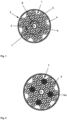
- Figure 1 shows a cross section of an optical cored wire 2 comprising an outer metal coat respectively metal jacket 3, a plurality of strands 4, an inner plastic tube 5, also called semi tight jacket, and an optical fiber 6 within the plastic tube 5.
- the outer circumference of the optical fiber 6 is smaller than the inner diameter of the plastic tube 5.
- the strands 4 are volumized and formed from a plurality of E-glass fibers.
- the strands 4 are twisted around the plastic tube 5 and form a rope. Alternate layers of strands are arranged in clockwise 7 and then counter clockwise 8 directions.
- the optical fiber 6 is in the center of the rope.
- the outer jacket is formed from low carbon steel.
- Figure 2 shows a cross section of an alternate optical cored wire 2 comprising an outer metal coat respectively metal jacket 3, a plurality of strands 4 formed from E-glass, a plurality of strands of an alternate material 4a forming a mixture with the strands 4 formed from E-glass, an inner plastic tube 5, also called semi tight jacket, and an optical fiber 6 within the plastic tube 5.
- the outer circumference of the optical fiber 6 is smaller than the inner diameter of the plastic tube 5.
- the strands 4 and 4a are volumized and formed from a plurality glass fibers.
- the strands 4 and 4a are twisted around the plastic tube 5 and form a rope. Alternate layers of strands are arranged in clockwise and then counter clockwise directions.
- the optical fiber 6 is in the center of the rope.
- the outer jacket is formed from low carbon steel.
- Figure 3 show the profile of the preferred embodiment tube closure, a lap seam 15 and alternatively a countersunk lap seam 16 and a grooved flat lock seam 17 known in the art and referenced to in the specification.
- Figure 4 shows a cross section of the optical cored wire 2 immersed into molten metal 12. Due to the high temperature of the molten steel 12, material surrounding the optical fiber 2 is progressively melted 9 due to the above mentioned reasons. As a result, an optical fiber tip 10 protrudes from a gob of intermediate material 11 whose excess 11a floats away. After a measurement, the optical cored wire is allowed to fully melt back to the top surface of the liquid metal 13.
- a cored wire 2 a graded index 62.5/125 ⁇ semi tight 0.9mm jacket optical fiber with an intermediate layer (1) of low melting E-glass surrounded by a 1mm metal steel outer layer closed by a lap seam comprising at least 50% Fe is used on a cored wired feeding system.
- a graded index 50/125 ⁇ or 62.5/125 ⁇ loose jacket optical fiber can be used.
- the optical cored wire 2 maybe de-spooled from a sitting coil 20 or a roll stand 20a by a cored wire feeder 24 and pushed into a guide tube 25 connected to the inner passage of an immersion nozzle 21 by connector 29 such that optical fiber tip 10 reaches the measuring position 23.
- Figure 5 depicts a metallurgical vessel with a roof 22 and a floor 26 but other melting vessels, molten metal transfer or holding vessels are also applicable.
- the cored wire 2 is fed through the gas cooled immersion nozzle 21 installed in an upper vessel wall 22 where the exit opening 21a of nozzle 21 is within the interior of the vessel.
- the blowing lance 21 is a concentrically constructed tube within a tube.
- the cored wire is fed through the internal tube while air is fed through an attachment 27 into the annular space between the inner diameter of the outer tube and the outer diameter of the inner tube and exiting at a location 28 within the vessel.
- the absolute amount of cooling air should be chosen such to prevent slag closing off the lance outlet even when the furnace slag is foamed, and thus the outlet 21a will be within the slag layer 14.
- the location of the immersion nozzle 21 can be in a variety of positions, the essential installation principle is that nozzle has a direct line access to the surface 13 of the molten steel 12 starting from a position above the molten steel bath.
- Figure 6 shows a preferred E-glass materials composition with 43 to 74 mol% SiO2, 0 to 8,5 mol% B2O3, 6 to 10 mol% Al2O3, 0,5 to 9 mol% MgO, 15 to 28 mol% CaO, up to 2,5 mol% Na2O, up to 0,05 mol% K2O, up to 0,3 mol% Fe2O3, up to 1 mol% TiO2 and/or up to 2 mol% F.
- Figure 7 shows a fiber material chemical composition of Basalt rock with about 52,8 mol% SiO2, about 17,5 mol% Al2O3, about 10,3 mol% Fe2O3, about 4,63 mol% MgO, about 8,59 mol% CaO, about 3,34 mol% Na2O, about 1,46 mol% K2O, about 1,38 mol% TiO2, about 0,28 mol% P2O5, about 0,16 mol% MnO and/or about 0,06 mol% Cr2O3.
- Figure 8 shows a diagram of viscosity over temperature of exemplary fiber materials.
- the very left curve refers to soda-lime glass and the adjacent curve to borosilicate glass. These materials are commonly "molten” or “fused” in the sense of the present application at a viscosity of 10 to 10000 poise in a temperature range of about 1200 to 1400 °C. Softening points of these materials are above 600 °C.
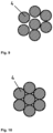
- Figures 9 and 10 show a cross section of a strand which consists of a plurality of for example E-glass fibers 1.
- the strand shown in figure 9 is volumized.
- the strand shown in figure 10 is not volumized. For this reason, the pattern of the fibers of figure 9 is less regular than the pattern of the fibers 4 of figure 10 . Further, the volumized fibers 4 shown in figure 9 are less compact compared with the fibers 4 shown in figure 10 .
Landscapes
- Physics & Mathematics (AREA)
- General Physics & Mathematics (AREA)
- Spectroscopy & Molecular Physics (AREA)
- Optics & Photonics (AREA)
- Chemical & Material Sciences (AREA)
- Metallurgy (AREA)
- Materials Engineering (AREA)
- Organic Chemistry (AREA)
- Engineering & Computer Science (AREA)
- Radiation Pyrometers (AREA)
- Light Guides In General And Applications Therefor (AREA)
- Optical Fibers, Optical Fiber Cores, And Optical Fiber Bundles (AREA)
- Measuring Temperature Or Quantity Of Heat (AREA)
- Treatment Of Steel In Its Molten State (AREA)
- Surface Treatment Of Glass Fibres Or Filaments (AREA)
Description
- The invention relates to a consumable cored wire comprising an optical fiber surrounded by a cover for measuring a temperature of a molten steel bath.
- JPH0815040 (A) describes a method that feeds a consumable optical fiber into liquid metal for measuring the temperature of molten metal baths. A similar method and apparatus for optical fiber measurements of molten metals is also described in
US 5,730,527 . Consumable optical fibers of this kind are known, for example, fromJPH11160155 (A - Improvements to these early consumable optical fibers comprise additional protection structures and are known for example from
JPH10176954 (A JPH09304185 (A - Since heat, from any source degrades the fiber, it should be protected from heat gain just prior to immersion. Likewise the remaining unused portion must also be protected from heat gain after a measurement to be suitable for the next measurement.
-
US 5,585,914 teaches that a consumable optical fiber can be fed through a nozzle into a molten metal at a rate of 5 mm/sec for 10 seconds then holding this immersion for 20 seconds and when accomplished in a cyclic fashion can be considered continuous.JPH09304185 (A - To accomplish this replacement, the fiber is fed into the molten metal until its temperature response exceeds a set point. The feeding is stopped for 2 seconds and a temperature determined. The fiber is then fed again into the metal for 10mm and stopped for two seconds, and a second temperature is determined. A comparison of the first and seconds temperatures determines if a successful measurement has been achieved or that additional cycles are needed. Besides for a means to determine if the reading is acceptable, the speed of feeding is not specified.
- Additionally, since steelmaking is a batch process, the above prior art suffers from the fact that a prior measurement using the remaining portion of coiled optical fiber will be devitrified and therefore one cannot follow this method since the initial determination of the set point temperature of the next measurement cannot be adequately determined.
JPH09243459 (A - In practice this requires additional equipment to cut away the damaged portion of the fiber and in the case where the immersion is from above the metal it must be withdrawn through a layer of slag which may collect on the fiber interfering with the removal from the vessel and the cutting mechanism.
- A variety of schemes to feed consumable optical fiber all are designed to expose the optical fiber core to the molten metal before devitrification however, the devitrification rate is dependent upon the actual conditions of the molten metal such as it temperature, its motion, the containment vessel and the slag covering the bath as well as the thermal conditions that the optical fiber is exposed to before and after each measurement cycle.
- It has been found that since the availability of a fresh fiber surface is essential for an accurate temperature measurement and this availability depends upon how the fiber is immersed into the molten metal then multiple feeding schemes are likely to arise due to the numerous variety of conditions that the fiber will be exposed to when immersed into and through various metallurgical vessels at various times during metals processing.
- When variation in the rate of devitrification can be minimized by improvement in the consumable optical fiber construction, the applicability of the measuring technique can apply to a wider range of metallurgical vessels without customization of the feeding regime.
- Multi-layered wire structures with a steel outer covering are used in steelworks to introduce doping substances selectively into the molten steel bath. These are typically called cored wires and are described in
DE19916235A1 ,DE3712619A1 ,DE19623194C1 andUS 6,770,366 .US 7,906,747 discloses a cored wire comprising a material which pyrolizes upon contact with a liquid metal bath. -
US 5,988,545 discloses a cored wire injection system where cored wires are supplied in coils or on spools such as for integration with special wire feeding machines such as disclosed inEP 0806640 ,JPH09101206 (A JPS6052507 (A DE3707322 (C1 ) to carry out the practical immersion of the cored wire. -
US 7,748,896 discloses a device for measuring a parameter of a molten bath, the device comprising an optical fiber, a cover laterally surrounding the optical fiber, and a detector connected to the optical fiber, wherein the cover surrounds the optical fiber in a plurality of layers, one layer comprising a metal tube and an intermediate layer arranged beneath the metal tube, the intermediate layer comprising a powder or a fibrous or granular material, wherein the material of the intermediate layer surrounds the fiber in a plurality of pieces. - The intermediate layer is formed of silicon dioxide powder or aluminum oxide powder and may contain a gas producing material. The disclosed feature of the intermediate layer surrounding the fiber in a plurality of separate parts means in the sense of the invention that the construction in multiple parts exists in the operating state, in other words during or after immersion in the molten bath to be measured such that the pieces of the intermediate layer remain separate and are separable during use. The addition of a gas producing material aids in the explosive separation of the parts of the intermediate layer.
- While the parts are contained within the un-melted outer metal jacket, this optical cored wire structure aids in keeping the optical fiber at its center at a very low temperature for a relatively long time. Devitrification from elevated temperatures that will destroy the optical fiber is delayed. From a particular temperature onwards during immersion into molten metal, expansion of the gases of the intermediate layer forcibly remove the un-attached cover layers.
- The fiber is heated erratically to the equilibrium temperature in the molten metal bath, so that the measurement can then take place very quickly before the optical fibre or its end immersed in the molten metal bath is devitrified. This unpredictability of the explosive nature of the gas evolution to reveal a fresh optical surface provides erratic results which are subject to interpretation and misread of the correct temperature.
- According to the known requirement of accurate temperature measurements by immersed optical fiber, the optical fiber must be consumed at a rate which is equal to or faster than the rate of devitrification of the optical core. Since the rate of devitrification is both a function of the amount of heat input to the optical core during its molten metal immersion and heat input to the optical core from exposure to the environment surrounding the cored optical fiber must be allowed to be consumed in proportion to pre-exposure conditions such as the radiant heat at the immersion location, the slag temperature as well as the melt temperature of the particular furnace. Other heat resistant optical cables comprise an intermediate layer made of glass wool between the optical core and an outer metal tube (
JPS56132302 US4284842 ). - The object of the invention is to further improve the measuring of the temperature in a molten steel bath.
- The object is solved by an improved cored wire comprising the features of the
independent claim 1. Preferred embodiments comprise the features of the sub-claims. The invention concerns a cored wire for measuring a temperature of a molten metal comprising an optical fiber and a cover laterally surrounding the optical fiber, wherein the cover surrounds the optical fiber in a plurality of layers, one layer comprising a metal tube and an intermediate layer arranged beneath the metal tube, wherein the intermediate layer, the entire intermediate layer and/or the cover laterally surrounding the optical fiber can melt immediately with immersion into or immediate exposure to the molten metal. - The term "melting" for materials other than metals with a distinct melting temperature refers within the scope of this application to a material condition, which is fluid enough to readily flow under its own weight or pushed by the weight of another liquid such as opposing liquid metal. Glass material can thus be particularly described as "molten" having a viscosity of 10 to 10000 poise, preferably 10 to 1000 poise.
Figure 8 shows the viscosity of glass material over temperature. - "Immediately with immersion" means at the time of direct contact with molten metal. However, when the entire intermediate layer comprises metal, "immediately with immersion" includes the time of heating up such metal components to melting temperature to become fluid. In the latter case, "immediately with immersion" implies that such metal components are few and small enough to melt immediately, for example in less than a second.
- For the below in detail described reasons, reliable measurement can thereby be achieved.
- In one embodiment, the cored wire has an immersion side for immersion into the molten metal and an opposite side, wherein the intermediate layer is composed in such a way that the intermediate layer is molten during immersion into the molten metal at the immersion side and at the same time remains unmelted and/or porous at the opposite side.
- Having a cored wire with an immersion side, where the intermediate layer can melt during immersion, and an opposite side with an unmelted intermediate layer, the optical fiber can be well protected by the intermediate layer for a reliable measurement. Unmelted and/or porous intermediate layer can provide good insulation of the optical fiber.
- In one embodiment, the optical fiber is arranged centrally in the cored wire and/or covered by a tube or sheath of plastic. An effective protection of the optical fiber can thereby be achieved.
- In one embodiment, the cored wire comprises an intermediate layer with a lower melting point than the metal, preferably less than 90% or 50 % to 85% of the melting point of the metal, wherein the temperature of the melting point is measured in °C
- The term "melting point" within the scope of this application shall be understood in the above described meaning of "melting" for non-metals and not interchanged with melting points or melting temperatures sometimes suggested for example for glass materials. The "melting point" of
Figure 8 at 100 poise is therefore not a melting point for glass within the meaning of the present application. - A stationary condition of protecting gob of molten intermediate layer and thus a reliably measurement can thereby be achieved.
- In one embodiment, the intermediate layer can form a gob of molten intermediate layer in a stationary condition surrounding the optical fiber during measuring.
- Stationary condition means that the liquid gob around the optical fiber remains despite material outflow and inflow such that excess molten gob material is leaving the gob while new gob material for substituting said material loss is resupplied by the melting cover laterally surrounding the optical fiber and/or melting intermediate layer.
- Reliable measurement with a continuously renewing optical fiber with reduced disturbances due to surrounding cover can be achieved.
- In one embodiment, the intermediate layer can provide an unmelted density as weight divided by porous structure volume, which is at least 30% higher and/or at most 100% higher than a melted density as the weight divided by conglomerated molten material volume.
- To illustrate the meaning of unmelted and melted density, a ball of glass wool may serve as an example. A ball of glass wool is a very light and fluffy material even though the physical property of the glass making up the wool is a high viscosity liquid material. The light and fluffy material occupies a volume and if one takes the weight and the volume of this glasswool ball the unmelted density can be calculated. After heating the same glasswool up to its glassmaking melting temperature, it will flow like a liquid. The glasswool will collect upon itself and form a puddle of glass. The volume that the puddle occupies and the weight which is the same as the weight of the starting glass wool ball are divided to calculate the melted density. These are two different densities but they arise from the state of the intermediate layer before and/or during use.
- The melted density is that of the gob formed at the optical fiber projection or tip surface of the optical fiber. The gob has an interface which contacts the steel and this interface is liquid to liquid. The opposite gob interface is a liquid to solid interface and it contacts the unmelted intermediate layer that feeds the liquid gob with newly melted material.
- An unmelted density of at least 30% higher and/or at most 100% higher than the melted density enables reliable measurement results. This ratio is important because the intermediate layer is insulating when unmelted to protect the unused optical fiber. The intermediate layer can thus change from unmelted to melted density during use when the intermediate layer is exposed to molten metal and collects upon itself particularly under its own surface tension and the action of the molten metal pushing upon it. The higher density in the metal promotes a good thermal exchange with the optical fiber and helps to carry away an excess molten gob and devitrified optical fiber while exposing a new surface.
- In one embodiment, the intermediate layer has a melted density, which corresponds to at least 15 % and/or at most 60% of 7 g/cm3 or common melted metal density.
- The density of the molten intermediate layer verses 7 g/cm3 or that of molten steel in the range of at least 15 % and/or at most 60% is relatively constant for molten metals since for example all silica based glasses particularly with alkali earth silicate (AES) and steel are still in narrow band with respect to the variation in density ratio. For example, both molten glass and molten metal density vary in the same direction with respect to temperature.
- In one embodiment, a rate of removal of the gob of molten intermediate layer from a surface of an optical fiber projection can depend on a density difference between the liquid gob and the liquid molten metal.
- The optical fiber projection is the tip of the optical fiber which generally is protruding at the immersion side from the cored wire during measurement.
- The rate of removal of the gob refers to the amount of excess molten gob leaving the gob over a period of time. Removal of gob from the tip surface is a function of the difference in density between liquid gob and liquid metal and as such is repeatable in practice since the ratio has low variation in practice. It generally applies for metal,steel, iron, copper etc.
- The gob can thereby get replenished from the melting of the intermediate layer and thus a consuming cored wire can maintain a relative sized gob always replenishing the excess molten gob material that has flowed away.
- In one embodiment, the cored wire or the metal tube is not gas tight particularly by means of a lap seam or gas tight particularly by means of a lock seam, for example a countersunk lap seam or grooved flat lock seam.
- The metal tube generally refers to an outer metal jacket or outer metal coat. The density of the unmelted intermediate layer or layers provides for open porosity behind the molten gob during measurement.
- The cored wire or the metal tube can be designed to be not gas tight, preferably by a lap seam with little production expenditures. Such not gas tight design or providing a lap seam will enable gas in the internal structure of the cored wire to move away from the gob inside the metal tube through the porous intermediate layer and also through the seam.
- Alternatively, the cored wire or the metal tube can be designed to be gas tight, preferably with a lock seam with little production expenditures, enabling the same gas movement through the internal structure of the cored wire but not away from the gob by exit through the seam.
- The invention also concerns independently a cored wire comprising an optical fiber and a cover laterally surrounding the optical fiber. The cover surrounds the optical fiber in a plurality of layers. One layer is a metal coat also called metal jacket or metal tube. An intermediate layer is arranged beneath the metal tube also called filler. The intermediate layer is formed from a gas porous thermal insulating material having a melting point of at least 600°C or at least 1000°C and/or at most 1500°C, preferably 1000°C to 1400°C, more preferably 1200°C to 1400°C, such that the pieces of the intermediate layer are fluid upon exposure to the molten metal temperatures.
- An optical fiber is a flexible, transparent fiber. Optical fibers are used most often as a means to transmit light between the two ends of the fiber. An optical fiber maybe formed from glass or plastic. The material of the intermediate layer maybe E-glass, borosilicate glass, basalt alkaline earth silicates, and/or a mixture of these glasses. The metal coat respectively the metal jacket maybe formed from a strip of metal 0.5 to 1.5 mm thick, preferably 1.0mm thick with a Fe content greater than 50%, preferably low carbon steel and maybe formed into a tube with a lap seam. The seam is particularly mechanically formed, and not sealed by adhesive or glues.
- An appropriate time for utilization of this device, nearing the end of the refining process, the temperature of a steel bath is about 1600°C. When the cored wire arrives at the molten steel bath, the metal tube will melt and dissolve into the metal bath since the melting point of the intermediate layer material is much lower than the temperature of the molten steel bath.
- The intermediate layer will particularly melt to form a gob with a liquid interface against the liquid metal.
- A gob generally means a mass of molten material such as glass or metal.
- Parts of the gob will flow away immediately afterwards due to the melting point of the intermediate layer material being much lower than the temperature of the molten steel bath.
- One will appreciate that fused materials such as the glasses of the intermediate layer do not experience a distinct melting point as crystalline materials do, but soften over a fairly broad temperature range. This transition from a solid to a plastic-like behavior, called the transformation range, is distinguished by a continuous change in viscosity with temperature, thus in the scope of this invention the term melt as applied to the intermediate layer is used to encompass the temperature range where the material is fluid enough to readily flow under its own weight or pushed by the weight of an opposing liquid metal.
- This is a function of the glass chemistry and preferably a glass chemistry that at the temperature of use will generally result in a glass viscosity between 10 and 103 poise. The relationship of logarithm viscosity and temperature is known from E.B. Shand, Engineering Glass, Modern Materials, Vol. 6, Academic Press, New York, 1968, p. 262.
- It has been found that by fusing the material of the intermediate layer a molten gobular layer of material surrounds the optical fiber providing an initial protection and then will flow away from the optical fiber at a predictable rate which is a function of its molten viscosity and the difference in density between it and the molten steel. In a practical sense, the difference in densities of the molten metal bath and the molten gob formed from the intermediate layer, although both are a function of temperature and composition, they are relatively constant within the application range.
- Up until the time the optical cored wire is immersed, the central optical fiber is thermally insulated protected by the relative low density of the unmelted intermediate layer until the outer metal jacket melts away exposing the filler (intermediate layer) which subsequently melts and pools around the optical fiber. Since the melting temperature of the filler respectively intermediate layer is generally substantially lower than the molten metal temperature once exposed guarantees that it will always be in a molten, fluid state. The progressive melting of the intermediate layer can form a molten gob surrounding the optical fiber.
- The formation of a gob creates a liquid to liquid interface with the molten metal and at the same time a liquid to solid interface opposite the molten metal. The volume of an accumulating gob surrounding the optical fiber is limited by the density driven fluid forces acting upon its molten mass, and its surface tension. Any excess volume flows away from the liquid to liquid interface and is progressively resupplied at the liquid to solid interface, such that a stationary condition of a gob of molten intermediate layer surrounding the optical fiber can be reached. Thus the volume of molten glass material at the tip of the melting optical cored wire is relatively constant.
- It has become apparent that the variation between the density of the steel and that of the molten gob results in a more predicable mechanism for exposing and renewing the fresh optical surface. The upward force of the displaced metal on the molten material of the intermediate layer (filler material) pushes the molten gob back and away from the optical fiber which stands extended from the gobular filler and forms a projection. Without a reinforcing inner metal jacket as in the prior art, this projecting fiber is substantially weak. As the feeding progresses, a sufficient quantity of molten filler accumulates at the base and a portion of this quantity is dragged with the extended optical core into the molten metal until the upward force of the molten metal upon the accumulated gob fractures the optical fiber at its base.
- The rate of un-devitrified optical fiber exposed to the molten metal is therefore more dependent upon the nearly constant density ratio- gob/molten steel, and the depth of immersion thus allowing a wide tolerance for the rate of feed. It has been found that retraction of the molten gob from the advancing optical fiber tip projection leads to more repeatable detection opportunities.
- By providing the intermediate layer being formed from a gas porous thermal insulating material having a melting point in the temperature range of 600°C to 1500°C or 1 000°C to 1500°C, preferably at 1200°C to 1400°C, the violent "explosion" and expansion of the patents
US 7,748,896 andUS 2007/0268477 A1 can be eliminated and replaced by a more controllable exposure of the fiber to the bath. - The intermediate layer is formed from fibers. Fibers cannot discharge from the cored wire in advance like particles, when the cored wire is fed into the melt. A discharge prior to the arrival at the melt would reduce the thermal isolation for the optical fiber which would reduce the reliability of measurement results. No adhesive or resin is necessary for sticking the filler material together which eliminates the presence of materials that would have the potential for explosive gasification.
- In a preferred embodiment, the fibers are endless fibers. This facilitates reliability of the measurement. Further, endless fibers facilitate the production of the intermediate layer.
- A rope forms the intermediate layer. In general a rope is a group of fibers, which are twisted or braided together in order to combine them into a larger and stronger form. In the classical sense of the word, a rope is particularly composed of fibers that are collected into a yarn and multiple yarns can be collected into a strand of which several strands can be collected into a rope. The use of the word rope of the present invention should be taken in its broadest sense where it represents a general structure and maybe formed of a grouping of yarns and/or a grouping of strands, twine cords and the like forming a generally shape.
- The rope maybe of a single chemical composition. Thus the un-fused density, i.e. weight divided by volume of an arrangement of un-fused parts such as fibers, of an intermediate layer formed of a twisted or braided rope is a controllable function of the number of, and thickness of, the individual yarns/strands comprising the agglomerated form. More exactly, the resultant fused volume in relation to the starting volume per linear unit of rope is well controlled. This also avoids the above mentioned discharge problem in a more reliable manner and comes with good thermal isolation properties. As a result, the reliability of the measurement is further improved.
- The optical fiber is arranged in the center of the rope which further improves the quality and the reliability of the measurement results.
- The rope or strands of the rope are volumized. A strand as well as a rope within the meaning of the present invention is composed of a plurality of fibers. A volumized rope or strand are treated in such a way, sometimes called texturizing, to have fibers irregularly oriented out of the fabric plane. The fibers or strands can be drawn through a nozzle in which an airstream creates turbulence in order to volumize the rope or the strand. To volumize the rope or the strand decreases the apparent un-fused density while increases the thermal isolation and contributes to improved measurement results.
- The intermediate layer is formed from glass fibers, from E-glass. The basis of the glass fibers can be silica (SiO2), particularly with a melting point of up to 1200 °C. E-glass is an industrial common material and one suitable for the purpose of this invention, particularly ET91415TEXO, can be obtained from PPG Industries Cheswick, PA, USA. The TEX, the weight, of the preferred E-glass is 1420 (g/km). The pre-fused density of glass fibers are useful thermal insulator guides because of their high ratio of surface area to weight. As fused, the density is low compared with the density of the molten steel bath so that the fluid glass fiber material in the molten steel bath will immediately flow upwards, away from the fiber, contributing to improved measurement results. The melting point and softening point of glass fibers is lower than 1600°C and thus much lower than the temperature range of molten steel processes.
- Preferably, the density of the intermediate layer has a melted and unmelted density. The un-fused density or unmelted density of for example at least two fibers correspond to the weight of those at least two fibers divided by volume of those at least two fibers including the space in between them in a condition, in which both fibers are not softened or melt. The fused density or melted density of for example the above mentioned at least two fibers corresponds to the weight of those at least two fibers divided by volume of those at least two fibers fused together for example in form of a gob in a condition, in which both fibers are softened or melt.
- Preferably, the density or fused density of the material of the intermediate layer is less than 5 g/cm3, preferably less than 4 g/cm3, more preferably between 2.0 and 3.5 g/cm3. Since the density of molten steel is much higher, the material of the intermediate layer will flow immediately upwards upon melting of the outer metallic layer. Thus, improved measurement results are possible.
- Preferably the ratio of the density of the liquid intermediate layer to that of the molten metal is between 0.25 and 0.45 and more preferable a ratio between 0.32 to 0.38. Since the intermediate layer is more or less a woven rope structure it has a pre-melted density which is much less than its fused density and very insulative. The pre melted density of the intermediate layer is 0.3 to 1.7 g/cm3. And more preferably 0.4 to 1.0g/cm3.
- Preferably, the premelted density is such that from interface between the melted gob and the remaining unmelted intermediate layer is gas porous and permits the passage of combustion products of the intermediate layer in a direction opposite the fused intermediate layer material. Thus, improved measurement results are possible.
- In a preferred embodiment, the intermediate layer is arranged between the metal tube and a tube formed from plastic wherein the optical fiber is within the plastic tube. Alternatively, cardboard can be used instead of plastic. Improved measurement results are possible, especially when the outer diameter of the optical fiber is smaller than the inner diameter of the plastic tube.
- The preferred embodiment is a semi-tight buffer jacket but a loose jacket is also acceptable. The general construction known to the art is either a 62.5/125µm or alternately 50/125µm graded index fiber placed in a 0.9mm plastic tube in which the fiber is mechanically isolated from external forces. The material of the tube is generally plastic and more specifically a polyamid such as tradenames Nylon, or thermoplastic elastomers such as Hytrel, or similar materials as disclosed in publication, "Innovative continuous online determination of steel melt temperature by direct optical measurement in the melt." T. Lamp, et al., Final Report EUR 21428, Contract no. 7210-PR/204, 2005, p 13-17. These plastics typically provide stiffening for the fiber against outside microbending influences. Suitable telecom optical fibers as described can be obtained from Huber and Suhner AG,
Degersheimerstrasse 14, CH-9100 Herisau DE. The plastic tube can be filled with moisture-resistant gel which provides additional mechanical protection and a water barrier layer around the fiber. This filling material is generally petroleum or silicone-based compounds. - In an alternate embodiment, the rope maybe comprised of a group of yarns or strands where several units of this grouping may be of a different chemical composition. Thus the blending of yarns or strands of different chemical compositions can provide a simple manufacturing method of controlling the physical and chemical properties of a rope with a uniform overall thickness from center to its overall outer diameter.
- The alternate construction of 24 fiber strands with the 62.5/125µm or alternately 50/125µm graded index fiber with a 0.9mm semi-tight tube arranged in the middle of a fiber bundle. Eight of the 16 fiber strands of the bundle are E-glass and 8 strands can be Ecomab, an alkali earth silicate, (AES), material available from Keramab,
Haverheidelaan 4,B9140 Temse, BE, with a melting point of approximately 1330°C. A typical composition of AES material consists of 50-82%silica, 18-43% calcia and/or magnesia and less than 6% alumina, titania or zirconia and trace oxides. Wrapped about the bundle are an additional 8 more strands, of e-glass. Intotal 8 of 24 strands are AES, the balance of e-glass serving to lower the melting temperature of the mixed fibers. The density of the intermediate layer as constructed is particularly approximately 0.51 g/cm3. The intermediate fiber layer is then preferably covered by a lap seam metal jacket tube of at least 50% Fe of approximately 1mm. - The foregoing summary, as well as the following detailed description of the invention, will be better understood when read in conjunction with the appended drawings. For the purpose of illustrating the invention, there are shown in the drawings embodiments which are presently preferred. It should be understood, however, that the invention is not limited to the precise arrangements and instrumentalities shown. In the drawings:
- Fig. 1
- is a cross section of an optical cored wire showing an intermediate layer of a rope like form about a center optical fiber
- Fig. 2
- is a cross section of an optical cored wire showing an intermediate layer of a rope like form in which alternate material strands have been introduced to influence its physical properties about a center optical fiber;
- Fig. 3
- shows possible closures of the outer tube known in the art
- Fig. 4
- is a cross section of molten steel within a vessel wherein a cored wire is immersed in the molten steel;
- Fig. 5
- is a system for measuring the temperature of molten steel;
- Fig. 6
- shows the composition of the E-glass
- Fig. 7
- shows composition of basalt rock from which basalt glass is made
- Fig. 8
- is a plot of glass viscosity verses temperature for select glasses.
- Fig. 9
- is a cross section of a volumized strand of fibers.
- Fig. 10
- is a cross section of a not-volumized strand of fibers.
-
Figure 1 shows a cross section of an optical coredwire 2 comprising an outer metal coat respectivelymetal jacket 3, a plurality ofstrands 4, an innerplastic tube 5, also called semi tight jacket, and anoptical fiber 6 within theplastic tube 5. The outer circumference of theoptical fiber 6 is smaller than the inner diameter of theplastic tube 5. Thestrands 4 are volumized and formed from a plurality of E-glass fibers. - The
strands 4 are twisted around theplastic tube 5 and form a rope. Alternate layers of strands are arranged in clockwise 7 and then counter clockwise 8 directions. Theoptical fiber 6 is in the center of the rope. The outer jacket is formed from low carbon steel. -
Figure 2 shows a cross section of an alternate optical coredwire 2 comprising an outer metal coat respectivelymetal jacket 3, a plurality ofstrands 4 formed from E-glass, a plurality of strands of analternate material 4a forming a mixture with thestrands 4 formed from E-glass, an innerplastic tube 5, also called semi tight jacket, and anoptical fiber 6 within theplastic tube 5. The outer circumference of theoptical fiber 6 is smaller than the inner diameter of theplastic tube 5. Thestrands strands plastic tube 5 and form a rope. Alternate layers of strands are arranged in clockwise and then counter clockwise directions. Theoptical fiber 6 is in the center of the rope. The outer jacket is formed from low carbon steel. -
Figure 3 show the profile of the preferred embodiment tube closure, alap seam 15 and alternatively acountersunk lap seam 16 and a groovedflat lock seam 17 known in the art and referenced to in the specification. -
Figure 4 shows a cross section of the optical coredwire 2 immersed intomolten metal 12. Due to the high temperature of themolten steel 12, material surrounding theoptical fiber 2 is progressively melted 9 due to the above mentioned reasons. As a result, anoptical fiber tip 10 protrudes from a gob ofintermediate material 11 whose excess 11a floats away. After a measurement, the optical cored wire is allowed to fully melt back to the top surface of theliquid metal 13. - As shown in
figure 5 , a coredwire 2, a graded index 62.5/125µ semi tight 0.9mm jacket optical fiber with an intermediate layer (1) of low melting E-glass surrounded by a 1mm metal steel outer layer closed by a lap seam comprising at least 50% Fe is used on a cored wired feeding system. Alternatively, a graded index 50/125µ or 62.5/125µ loose jacket optical fiber can be used. The optical coredwire 2 maybe de-spooled from a sittingcoil 20 or aroll stand 20a by a coredwire feeder 24 and pushed into aguide tube 25 connected to the inner passage of animmersion nozzle 21 byconnector 29 such thatoptical fiber tip 10 reaches the measuringposition 23.Figure 5 depicts a metallurgical vessel with aroof 22 and afloor 26 but other melting vessels, molten metal transfer or holding vessels are also applicable. - Starting from a location outside the vessel, the cored
wire 2 is fed through the gas cooledimmersion nozzle 21 installed in anupper vessel wall 22 where theexit opening 21a ofnozzle 21 is within the interior of the vessel. The blowinglance 21 is a concentrically constructed tube within a tube. The cored wire is fed through the internal tube while air is fed through anattachment 27 into the annular space between the inner diameter of the outer tube and the outer diameter of the inner tube and exiting at alocation 28 within the vessel. The absolute amount of cooling air should be chosen such to prevent slag closing off the lance outlet even when the furnace slag is foamed, and thus theoutlet 21a will be within theslag layer 14. Although the location of theimmersion nozzle 21 can be in a variety of positions, the essential installation principle is that nozzle has a direct line access to thesurface 13 of themolten steel 12 starting from a position above the molten steel bath. -
Figure 6 shows a preferred E-glass materials composition with 43 to 74 mol% SiO2, 0 to 8,5 mol% B2O3, 6 to 10 mol% Al2O3, 0,5 to 9 mol% MgO, 15 to 28 mol% CaO, up to 2,5 mol% Na2O, up to 0,05 mol% K2O, up to 0,3 mol% Fe2O3, up to 1 mol% TiO2 and/or up to 2 mol% F. -
Figure 7 shows a fiber material chemical composition of Basalt rock with about 52,8 mol% SiO2, about 17,5 mol% Al2O3, about 10,3 mol% Fe2O3, about 4,63 mol% MgO, about 8,59 mol% CaO, about 3,34 mol% Na2O, about 1,46 mol% K2O, about 1,38 mol% TiO2, about 0,28 mol% P2O5, about 0,16 mol% MnO and/or about 0,06 mol% Cr2O3. -
Figure 8 shows a diagram of viscosity over temperature of exemplary fiber materials. - The very left curve refers to soda-lime glass and the adjacent curve to borosilicate glass. These materials are commonly "molten" or "fused" in the sense of the present application at a viscosity of 10 to 10000 poise in a temperature range of about 1200 to 1400 °C. Softening points of these materials are above 600 °C.
-
Figures 9 and 10 show a cross section of a strand which consists of a plurality of for exampleE-glass fibers 1. The strand shown infigure 9 is volumized. The strand shown infigure 10 is not volumized. For this reason, the pattern of the fibers offigure 9 is less regular than the pattern of thefibers 4 offigure 10 . Further, thevolumized fibers 4 shown infigure 9 are less compact compared with thefibers 4 shown infigure 10 . -
- 1:
- intermediate layer
- 2:
- optical cored wire
- 3:
- metal coat; metal tube; metal jacket
- 4:
- strand consisting of a plurality of fibers
- 4a
- strand consisting of a plurality of fibers of a different composition
- 5:
- semi-tight jacket; plastic or cardboard tube
- 6:
- optical fiber
- 7:
- molten steel
- 8:
- vessel; ladle
- 9:
- slag
- 10:
- optical fiber projection; tip
- 11
- molten gob
- 11a
- excess molten gob material
- 12
- molten metal
- 13
- molten metal surface level
- 14
- slag layer
- 15
- lap seam closure
- 16
- countersunk lap seam closure
- 17
- grooved flat lock seam closure
- 18
- -
- 19
- -
- 20:
- sitting roll
- 21
- immersion nozzle
- 21a
- immersion nozzle outlet
- 22
- vessel roof
- 23
- measuring position
- 24
- cored wire feeding machine
- 25
- guide tube
- 26
- vessel floor
- 27
- gas purge inlet
- 28
- exiting purge gas
- 29
- connector
- 30
- Soda-lime glass
- 31
- Borosilicate glass
- 32
- 96% silica glass
- 33
- Fused silica
- 34
- Strain point
- 35
- Annealing point
- 36
- Softening point
- 37
- Working range
- 38
- Working point
- 39
- Melting point
- E
- Typical E glass
- A
- Approximate limits
- C
- Composition
- T
- Temperature
- V
- Viscosity
Claims (13)
- A cored wire (2) for a consumable optical cable for measuring a temperature of a molten steel bath the cored wire (2) comprising an optical fiber (6) and a cover laterally surrounding the optical fiber, wherein the cover surrounds the optical fiber in a plurality of layers, one layer comprising a metal tube (3) and an intermediate layer (1) being formed from E-glass fibers and arranged beneath the metal tube (3), wherein the intermediate layer (1) is formed from a material having a melting point of at least 600°C or at least 1000°C and/or at most 1500°C, the cored wire being characterized in that a rope forms the intermediate layer (1), wherein the rope is volumized so that fibers are irregularly oriented out of the fabric plane and wherein the optical fiber (6) is arranged in the center of the rope.
- The cored wire (2) of the preceding claim, wherein the fibers (4, 4a) are endless fibers.
- The cored wire of one of the preceding claims, wherein the intermediate layer (1) is arranged between the metal tube (3) and a tube (5) formed from plastic or cardboard and wherein the optical fiber (6) is within the plastic or cardboard tube (5).
- The cored wire of the preceding claim, wherein the outer diameter of the optical fiber (6) is smaller than the inner diameter of the tube (5) formed from plastic or cardboard so that the optical fiber (6) is moveable within the tube (5) formed from plastic or cardboard.
- The cored wire of one of the preceding claims, wherein the density of the material of the intermediate layer (1) is less than 5 g/cm3, preferably less than 4 g/cm3, more preferably less than 3 g/cm3.
- The cored wire of one of the preceding claims, wherein the intermediate layer (1), the entire intermediate layer (1) and/or the cover laterally surrounding the optical fiber (6) can melt immediately at the time of direct contact with the molten metal with immersion into or immediate exposure to the molten metal (12).
- A cored wire (2) of one of the preceding claims, wherein the optical fiber (6) is arranged centrally in the cored wire (2) and/or covered by a tube (5) of plastic.
- A cored wire (2) of one of the preceding claims, wherein the intermediate layer (1) has a lower melting point than the metal, preferably less than 90% or 50 % to 85% of the melting point of the metal.
- A cored wire (2) of one of the preceding claims, wherein the intermediate layer (1) has a melted density, which corresponds to at least 15 % and/or at most 60% of 7 g/cm3 or common melted metal density.
- A cored wire (2) of one of the preceding claims, wherein an unmelted density of the intermediate layers (1) provides for open porosity behind a molten gob (11).
- A cored wire (2) of one of the preceding claims, wherein the cored wire (2) or the metal tube (3) is not gas tight particularly by means of a lap seam (15) or gas tight particularly by means of a lock seam, for example a countersunk lap seam (16) or grooved flat lock seam (17).
- A cored wire (2) of one of the preceding claims, wherein the intermediate layer (1) is formed from a material having a melting point of 1000°C to 1400°C.
- A cored wire (2) of one of the preceding claims, wherein the intermediate layer (1) is formed from a material having a melting point of 1200°C to 1400°C.
Applications Claiming Priority (1)
| Application Number | Priority Date | Filing Date | Title |
|---|---|---|---|
| GB1518208.2A GB2543318A (en) | 2015-10-14 | 2015-10-14 | Consumable optical fiber for measuring a temperature of a molten steel bath |
Publications (2)
| Publication Number | Publication Date |
|---|---|
| EP3156835A1 EP3156835A1 (en) | 2017-04-19 |
| EP3156835B1 true EP3156835B1 (en) | 2024-02-28 |
Family
ID=55131049
Family Applications (1)
| Application Number | Title | Priority Date | Filing Date |
|---|---|---|---|
| EP16185902.0A Active EP3156835B1 (en) | 2015-10-14 | 2016-08-26 | Consumable optical fiber for measuring a temperature of a molten steel bath |
Country Status (13)
| Country | Link |
|---|---|
| US (1) | US10295411B2 (en) |
| EP (1) | EP3156835B1 (en) |
| JP (1) | JP6779739B2 (en) |
| KR (1) | KR102242432B1 (en) |
| CN (1) | CN107036731B (en) |
| AR (1) | AR106323A1 (en) |
| AU (1) | AU2016222484B2 (en) |
| BR (1) | BR102016023435B1 (en) |
| CA (1) | CA2940552C (en) |
| GB (1) | GB2543318A (en) |
| RU (1) | RU2719353C2 (en) |
| TW (1) | TWI633347B (en) |
| UA (1) | UA122669C2 (en) |
Families Citing this family (3)
| Publication number | Priority date | Publication date | Assignee | Title |
|---|---|---|---|---|
| EP3929548A1 (en) | 2020-06-22 | 2021-12-29 | Heraeus Electro-Nite International N.V. | Device and method for measuring a temperature of a molten metal |
| EP3957414B1 (en) | 2020-08-20 | 2025-02-19 | Heraeus Electro-Nite International N.V. | Device and system for measuring a temperature of a molten metal |
| EP4009021A1 (en) * | 2020-12-02 | 2022-06-08 | Heraeus Electro-Nite International N.V. | Method and system for determining a series of temperature values of a molten metal bath |
Citations (1)
| Publication number | Priority date | Publication date | Assignee | Title |
|---|---|---|---|---|
| JP2000121446A (en) * | 1998-10-15 | 2000-04-28 | Nkk Corp | Consumable optical fiber temperature measuring device |
Family Cites Families (39)
| Publication number | Priority date | Publication date | Assignee | Title |
|---|---|---|---|---|
| US3943271A (en) * | 1974-05-06 | 1976-03-09 | General Cable Corporation | Extruded solid dielectric high voltage cable resistant to electro-chemical trees |
| US4284842A (en) * | 1979-10-31 | 1981-08-18 | Bell Telephone Laboratories, Inc. | Cable having superior resistance to flame spread and smoke evolution |
| JPS56132302A (en) * | 1980-03-21 | 1981-10-16 | Fujikura Ltd | Optical fiber cable |
| DE3236395A1 (en) * | 1982-10-01 | 1984-04-05 | Licentia Patent-Verwaltungs-Gmbh, 6000 Frankfurt | FLAME-RESISTANT OPTICAL MESSAGE CABLE |
| JPS6052507A (en) | 1983-09-01 | 1985-03-25 | Nisshin Steel Co Ltd | Apparatus for guiding wire-shaped additive to molten metal |
| NO850581L (en) * | 1984-02-16 | 1985-08-19 | Standard Telephones Cables Ltd | UNDERWATER CABLE |
| US4723831A (en) * | 1985-12-02 | 1988-02-09 | American Telephone And Telegraph Company At&T Bell Laboratories | Optical fiber communications cable |
| DE3707322C1 (en) | 1987-03-07 | 1988-06-16 | Odermath Stahlwerkstechnik | Wire injection machine |
| DE3712619A1 (en) | 1987-04-14 | 1988-10-27 | Odermath Stahlwerkstechnik | Method for controlling a wire injection device, corresponding wire store and corresponding wire-advancing machine |
| GB9115888D0 (en) * | 1991-07-23 | 1991-09-04 | Bicc Plc | Electric & communications cables |
| JP3147101B2 (en) | 1992-02-03 | 2001-03-19 | 日本鋼管株式会社 | Method and apparatus for measuring temperature of molten metal |
| JPH0815040A (en) | 1994-06-29 | 1996-01-19 | Nkk Corp | Optical fiber temperature measuring device for high temperature liquids |
| KR0134654B1 (en) | 1993-10-05 | 1998-04-20 | 이요시 슌키치 | Apparatus and method for measuring a temperature using optical fiber |
| US6004031A (en) * | 1993-11-30 | 1999-12-21 | Nkk Corporation | Temperature measuring device |
| JP2795146B2 (en) * | 1993-11-30 | 1998-09-10 | 日本鋼管株式会社 | Double coated optical fiber for temperature measurement |
| JPH07324982A (en) | 1994-05-30 | 1995-12-12 | Nkk Corp | Consumable optical fiber thermometer |
| GB9419530D0 (en) * | 1994-09-28 | 1994-11-16 | Bicc Plc | Method of enclosing optical fibre element in a tube |
| JP3267122B2 (en) | 1995-10-03 | 2002-03-18 | 日本鋼管株式会社 | Temperature measurement device for high-temperature melt |
| JPH09243459A (en) | 1996-03-13 | 1997-09-19 | Mitsubishi Materials Corp | Optical temperature measuring device for high temperature liquid and measuring method by the device |
| DE69722305T2 (en) | 1996-04-09 | 2004-04-01 | Nkk Corp. | Device for measuring the temperature of molten metal |
| JPH09304185A (en) * | 1996-05-14 | 1997-11-28 | Tokai Carbon Co Ltd | Method and device for measuring temperature of molten metal |
| DE19623194C1 (en) | 1996-06-11 | 1997-07-31 | Odermath Stahlwerkstechnik | Delivery of injection wire |
| JP3287246B2 (en) * | 1996-12-17 | 2002-06-04 | 日本鋼管株式会社 | Temperature measuring device for molten metal |
| US5988545A (en) | 1997-12-30 | 1999-11-23 | Minerals Technologies, Inc. | Method for storing and dispensing cored wire |
| DE19916235C2 (en) | 1999-03-01 | 2001-03-08 | Odermath Stahlwerkstechnik | Cored wire for the treatment of melts by wire injection |
| US6410181B1 (en) * | 1999-05-05 | 2002-06-25 | Wilson Greatbatch Ltd. | High temperature lithium oxyhalide electrochemical cell |
| US6770366B2 (en) | 2000-06-28 | 2004-08-03 | Affival S.A. | Cored wire for introducing additives into a molten metal bath |
| US6519397B2 (en) * | 2001-06-01 | 2003-02-11 | Owens Corning Fiberglas Technology, Inc. | Premises cable with fiberglass reinforcement |
| US6870995B2 (en) | 2001-07-05 | 2005-03-22 | Pirelli Cables And Systems Llc | High fiber count optical fiber cable with buffer tubes around central strength member |
| US6901192B2 (en) * | 2002-11-18 | 2005-05-31 | Neptco Incorporated | Cable strength member |
| WO2005081681A2 (en) | 2004-02-11 | 2005-09-09 | Fort Wayne Metals Research Products Corporation | Drawn strand filled tubing wire |
| US6964516B2 (en) * | 2004-02-11 | 2005-11-15 | Heraeus-Electro Nite International N.V. | Device and method for measuring temperature in molten metals |
| FR2871477B1 (en) | 2004-06-10 | 2006-09-29 | Affival Sa Sa | WIRE FOURRE |
| GB2438214A (en) * | 2006-05-19 | 2007-11-21 | Heraeus Electro Nite Int | Measuring a parameter of a molten bath |
| US7936957B1 (en) * | 2007-03-09 | 2011-05-03 | Superior Essex Communications, Lp | High-density fiber optic ribbon cable with enhanced water blocking performance |
| CN201570315U (en) * | 2009-07-14 | 2010-09-01 | 国网电力科学研究院武汉南瑞有限责任公司 | An intelligent temperature-measuring composite material core wire |
| CN201570288U (en) | 2009-07-24 | 2010-09-01 | 国网电力科学研究院武汉南瑞有限责任公司 | An intelligent monitoring three-dimensional stress composite core conductor |
| EP2512625A4 (en) * | 2009-12-15 | 2013-12-11 | Restek Corp | Gas chromatography inlet liners and sample path containers |
| EP2799824B1 (en) * | 2013-04-30 | 2019-10-23 | Heraeus Electro-Nite International N.V. | Method and apparatus for measuring the temperature of a molten metal |
-
2015
- 2015-10-14 GB GB1518208.2A patent/GB2543318A/en not_active Withdrawn
-
2016
- 2016-08-26 EP EP16185902.0A patent/EP3156835B1/en active Active
- 2016-08-29 CA CA2940552A patent/CA2940552C/en not_active Expired - Fee Related
- 2016-09-02 AU AU2016222484A patent/AU2016222484B2/en not_active Ceased
- 2016-09-21 TW TW105130493A patent/TWI633347B/en not_active IP Right Cessation
- 2016-09-28 RU RU2016138423A patent/RU2719353C2/en active
- 2016-10-07 BR BR102016023435-2A patent/BR102016023435B1/en active IP Right Grant
- 2016-10-11 AR ARP160103109A patent/AR106323A1/en active IP Right Grant
- 2016-10-12 US US15/291,146 patent/US10295411B2/en active Active
- 2016-10-13 KR KR1020160132692A patent/KR102242432B1/en active Active
- 2016-10-13 UA UAA201610405A patent/UA122669C2/en unknown
- 2016-10-13 JP JP2016201974A patent/JP6779739B2/en active Active
- 2016-10-13 CN CN201610894380.7A patent/CN107036731B/en active Active
Patent Citations (1)
| Publication number | Priority date | Publication date | Assignee | Title |
|---|---|---|---|---|
| JP2000121446A (en) * | 1998-10-15 | 2000-04-28 | Nkk Corp | Consumable optical fiber temperature measuring device |
Also Published As
| Publication number | Publication date |
|---|---|
| EP3156835A1 (en) | 2017-04-19 |
| GB2543318A (en) | 2017-04-19 |
| JP6779739B2 (en) | 2020-11-04 |
| BR102016023435A2 (en) | 2017-04-25 |
| GB201518208D0 (en) | 2015-11-25 |
| AR106323A1 (en) | 2018-01-03 |
| RU2016138423A3 (en) | 2019-11-14 |
| TW201715264A (en) | 2017-05-01 |
| AU2016222484B2 (en) | 2021-04-01 |
| UA122669C2 (en) | 2020-12-28 |
| US20170146408A1 (en) | 2017-05-25 |
| AU2016222484A1 (en) | 2017-05-04 |
| CA2940552A1 (en) | 2017-04-14 |
| RU2016138423A (en) | 2018-04-02 |
| RU2719353C2 (en) | 2020-04-17 |
| CN107036731A (en) | 2017-08-11 |
| CN107036731B (en) | 2020-08-14 |
| JP2017097336A (en) | 2017-06-01 |
| CA2940552C (en) | 2020-07-21 |
| KR102242432B1 (en) | 2021-04-20 |
| TWI633347B (en) | 2018-08-21 |
| KR20170044044A (en) | 2017-04-24 |
| BR102016023435B1 (en) | 2021-02-23 |
| US10295411B2 (en) | 2019-05-21 |
Similar Documents
| Publication | Publication Date | Title |
|---|---|---|
| KR102267529B1 (en) | Method for measuring a temperature of a molten metal bath | |
| AU2016222484B2 (en) | Consumable optical fiber for measuring a temperature of a molten steel bath | |
| US10203463B2 (en) | Cored wire, method and device for the production of the same | |
| EP0471152B1 (en) | Method of forming glass articles | |
| NO336395B1 (en) | Fiberglass forming compositions | |
| US3198615A (en) | Method and apparatus for melting heat-softenable materials | |
| JP2023552324A (en) | Method and system for determining temperature values of molten metal baths | |
| JP2023535761A (en) | Apparatus and system for measuring the temperature of molten metal |
Legal Events
| Date | Code | Title | Description |
|---|---|---|---|
| PUAI | Public reference made under article 153(3) epc to a published international application that has entered the european phase |
Free format text: ORIGINAL CODE: 0009012 |
|
| STAA | Information on the status of an ep patent application or granted ep patent |
Free format text: STATUS: REQUEST FOR EXAMINATION WAS MADE |
|
| 17P | Request for examination filed |
Effective date: 20160826 |
|
| AK | Designated contracting states |
Kind code of ref document: A1 Designated state(s): AL AT BE BG CH CY CZ DE DK EE ES FI FR GB GR HR HU IE IS IT LI LT LU LV MC MK MT NL NO PL PT RO RS SE SI SK SM TR |
|
| AX | Request for extension of the european patent |
Extension state: BA ME |
|
| STAA | Information on the status of an ep patent application or granted ep patent |
Free format text: STATUS: EXAMINATION IS IN PROGRESS |
|
| 17Q | First examination report despatched |
Effective date: 20180328 |
|
| GRAP | Despatch of communication of intention to grant a patent |
Free format text: ORIGINAL CODE: EPIDOSNIGR1 |
|
| STAA | Information on the status of an ep patent application or granted ep patent |
Free format text: STATUS: GRANT OF PATENT IS INTENDED |
|
| INTG | Intention to grant announced |
Effective date: 20231009 |
|
| GRAS | Grant fee paid |
Free format text: ORIGINAL CODE: EPIDOSNIGR3 |
|
| GRAA | (expected) grant |
Free format text: ORIGINAL CODE: 0009210 |
|
| STAA | Information on the status of an ep patent application or granted ep patent |
Free format text: STATUS: THE PATENT HAS BEEN GRANTED |
|
| AK | Designated contracting states |
Kind code of ref document: B1 Designated state(s): AL AT BE BG CH CY CZ DE DK EE ES FI FR GB GR HR HU IE IS IT LI LT LU LV MC MK MT NL NO PL PT RO RS SE SI SK SM TR |
|
| REG | Reference to a national code |
Ref country code: GB Ref legal event code: FG4D |
|
| REG | Reference to a national code |
Ref country code: CH Ref legal event code: EP |
|
| REG | Reference to a national code |
Ref country code: DE Ref legal event code: R096 Ref document number: 602016085987 Country of ref document: DE |
|
| REG | Reference to a national code |
Ref country code: IE Ref legal event code: FG4D |
|
| P01 | Opt-out of the competence of the unified patent court (upc) registered |
Effective date: 20240513 |
|
| REG | Reference to a national code |
Ref country code: LT Ref legal event code: MG9D |
|
| PG25 | Lapsed in a contracting state [announced via postgrant information from national office to epo] |
Ref country code: IS Free format text: LAPSE BECAUSE OF FAILURE TO SUBMIT A TRANSLATION OF THE DESCRIPTION OR TO PAY THE FEE WITHIN THE PRESCRIBED TIME-LIMIT Effective date: 20240628 |
|
| REG | Reference to a national code |
Ref country code: NL Ref legal event code: MP Effective date: 20240228 |
|
| PG25 | Lapsed in a contracting state [announced via postgrant information from national office to epo] |
Ref country code: LT Free format text: LAPSE BECAUSE OF FAILURE TO SUBMIT A TRANSLATION OF THE DESCRIPTION OR TO PAY THE FEE WITHIN THE PRESCRIBED TIME-LIMIT Effective date: 20240228 |
|
| PG25 | Lapsed in a contracting state [announced via postgrant information from national office to epo] |
Ref country code: GR Free format text: LAPSE BECAUSE OF FAILURE TO SUBMIT A TRANSLATION OF THE DESCRIPTION OR TO PAY THE FEE WITHIN THE PRESCRIBED TIME-LIMIT Effective date: 20240529 |
|
| PG25 | Lapsed in a contracting state [announced via postgrant information from national office to epo] |
Ref country code: RS Free format text: LAPSE BECAUSE OF FAILURE TO SUBMIT A TRANSLATION OF THE DESCRIPTION OR TO PAY THE FEE WITHIN THE PRESCRIBED TIME-LIMIT Effective date: 20240528 Ref country code: HR Free format text: LAPSE BECAUSE OF FAILURE TO SUBMIT A TRANSLATION OF THE DESCRIPTION OR TO PAY THE FEE WITHIN THE PRESCRIBED TIME-LIMIT Effective date: 20240228 Ref country code: NL Free format text: LAPSE BECAUSE OF FAILURE TO SUBMIT A TRANSLATION OF THE DESCRIPTION OR TO PAY THE FEE WITHIN THE PRESCRIBED TIME-LIMIT Effective date: 20240228 |
|
| PG25 | Lapsed in a contracting state [announced via postgrant information from national office to epo] |
Ref country code: ES Free format text: LAPSE BECAUSE OF FAILURE TO SUBMIT A TRANSLATION OF THE DESCRIPTION OR TO PAY THE FEE WITHIN THE PRESCRIBED TIME-LIMIT Effective date: 20240228 |
|
| PG25 | Lapsed in a contracting state [announced via postgrant information from national office to epo] |
Ref country code: RS Free format text: LAPSE BECAUSE OF FAILURE TO SUBMIT A TRANSLATION OF THE DESCRIPTION OR TO PAY THE FEE WITHIN THE PRESCRIBED TIME-LIMIT Effective date: 20240528 Ref country code: NO Free format text: LAPSE BECAUSE OF FAILURE TO SUBMIT A TRANSLATION OF THE DESCRIPTION OR TO PAY THE FEE WITHIN THE PRESCRIBED TIME-LIMIT Effective date: 20240528 Ref country code: NL Free format text: LAPSE BECAUSE OF FAILURE TO SUBMIT A TRANSLATION OF THE DESCRIPTION OR TO PAY THE FEE WITHIN THE PRESCRIBED TIME-LIMIT Effective date: 20240228 Ref country code: LT Free format text: LAPSE BECAUSE OF FAILURE TO SUBMIT A TRANSLATION OF THE DESCRIPTION OR TO PAY THE FEE WITHIN THE PRESCRIBED TIME-LIMIT Effective date: 20240228 Ref country code: IS Free format text: LAPSE BECAUSE OF FAILURE TO SUBMIT A TRANSLATION OF THE DESCRIPTION OR TO PAY THE FEE WITHIN THE PRESCRIBED TIME-LIMIT Effective date: 20240628 Ref country code: HR Free format text: LAPSE BECAUSE OF FAILURE TO SUBMIT A TRANSLATION OF THE DESCRIPTION OR TO PAY THE FEE WITHIN THE PRESCRIBED TIME-LIMIT Effective date: 20240228 Ref country code: GR Free format text: LAPSE BECAUSE OF FAILURE TO SUBMIT A TRANSLATION OF THE DESCRIPTION OR TO PAY THE FEE WITHIN THE PRESCRIBED TIME-LIMIT Effective date: 20240529 Ref country code: FI Free format text: LAPSE BECAUSE OF FAILURE TO SUBMIT A TRANSLATION OF THE DESCRIPTION OR TO PAY THE FEE WITHIN THE PRESCRIBED TIME-LIMIT Effective date: 20240228 Ref country code: ES Free format text: LAPSE BECAUSE OF FAILURE TO SUBMIT A TRANSLATION OF THE DESCRIPTION OR TO PAY THE FEE WITHIN THE PRESCRIBED TIME-LIMIT Effective date: 20240228 Ref country code: BG Free format text: LAPSE BECAUSE OF FAILURE TO SUBMIT A TRANSLATION OF THE DESCRIPTION OR TO PAY THE FEE WITHIN THE PRESCRIBED TIME-LIMIT Effective date: 20240228 |
|
| PG25 | Lapsed in a contracting state [announced via postgrant information from national office to epo] |
Ref country code: PT Free format text: LAPSE BECAUSE OF FAILURE TO SUBMIT A TRANSLATION OF THE DESCRIPTION OR TO PAY THE FEE WITHIN THE PRESCRIBED TIME-LIMIT Effective date: 20240628 Ref country code: PL Free format text: LAPSE BECAUSE OF FAILURE TO SUBMIT A TRANSLATION OF THE DESCRIPTION OR TO PAY THE FEE WITHIN THE PRESCRIBED TIME-LIMIT Effective date: 20240228 |
|
| REG | Reference to a national code |
Ref country code: AT Ref legal event code: MK05 Ref document number: 1661760 Country of ref document: AT Kind code of ref document: T Effective date: 20240228 |
|
| PG25 | Lapsed in a contracting state [announced via postgrant information from national office to epo] |
Ref country code: SE Free format text: LAPSE BECAUSE OF FAILURE TO SUBMIT A TRANSLATION OF THE DESCRIPTION OR TO PAY THE FEE WITHIN THE PRESCRIBED TIME-LIMIT Effective date: 20240228 Ref country code: PT Free format text: LAPSE BECAUSE OF FAILURE TO SUBMIT A TRANSLATION OF THE DESCRIPTION OR TO PAY THE FEE WITHIN THE PRESCRIBED TIME-LIMIT Effective date: 20240628 Ref country code: PL Free format text: LAPSE BECAUSE OF FAILURE TO SUBMIT A TRANSLATION OF THE DESCRIPTION OR TO PAY THE FEE WITHIN THE PRESCRIBED TIME-LIMIT Effective date: 20240228 Ref country code: LV Free format text: LAPSE BECAUSE OF FAILURE TO SUBMIT A TRANSLATION OF THE DESCRIPTION OR TO PAY THE FEE WITHIN THE PRESCRIBED TIME-LIMIT Effective date: 20240228 |
|
| PG25 | Lapsed in a contracting state [announced via postgrant information from national office to epo] |
Ref country code: DK Free format text: LAPSE BECAUSE OF FAILURE TO SUBMIT A TRANSLATION OF THE DESCRIPTION OR TO PAY THE FEE WITHIN THE PRESCRIBED TIME-LIMIT Effective date: 20240228 |
|
| PG25 | Lapsed in a contracting state [announced via postgrant information from national office to epo] |
Ref country code: SM Free format text: LAPSE BECAUSE OF FAILURE TO SUBMIT A TRANSLATION OF THE DESCRIPTION OR TO PAY THE FEE WITHIN THE PRESCRIBED TIME-LIMIT Effective date: 20240228 |
|
| PG25 | Lapsed in a contracting state [announced via postgrant information from national office to epo] |
Ref country code: CZ Free format text: LAPSE BECAUSE OF FAILURE TO SUBMIT A TRANSLATION OF THE DESCRIPTION OR TO PAY THE FEE WITHIN THE PRESCRIBED TIME-LIMIT Effective date: 20240228 Ref country code: EE Free format text: LAPSE BECAUSE OF FAILURE TO SUBMIT A TRANSLATION OF THE DESCRIPTION OR TO PAY THE FEE WITHIN THE PRESCRIBED TIME-LIMIT Effective date: 20240228 |
|
| PG25 | Lapsed in a contracting state [announced via postgrant information from national office to epo] |
Ref country code: AT Free format text: LAPSE BECAUSE OF FAILURE TO SUBMIT A TRANSLATION OF THE DESCRIPTION OR TO PAY THE FEE WITHIN THE PRESCRIBED TIME-LIMIT Effective date: 20240228 |
|
| PG25 | Lapsed in a contracting state [announced via postgrant information from national office to epo] |
Ref country code: SK Free format text: LAPSE BECAUSE OF FAILURE TO SUBMIT A TRANSLATION OF THE DESCRIPTION OR TO PAY THE FEE WITHIN THE PRESCRIBED TIME-LIMIT Effective date: 20240228 |
|
| PG25 | Lapsed in a contracting state [announced via postgrant information from national office to epo] |
Ref country code: SM Free format text: LAPSE BECAUSE OF FAILURE TO SUBMIT A TRANSLATION OF THE DESCRIPTION OR TO PAY THE FEE WITHIN THE PRESCRIBED TIME-LIMIT Effective date: 20240228 Ref country code: SK Free format text: LAPSE BECAUSE OF FAILURE TO SUBMIT A TRANSLATION OF THE DESCRIPTION OR TO PAY THE FEE WITHIN THE PRESCRIBED TIME-LIMIT Effective date: 20240228 Ref country code: RO Free format text: LAPSE BECAUSE OF FAILURE TO SUBMIT A TRANSLATION OF THE DESCRIPTION OR TO PAY THE FEE WITHIN THE PRESCRIBED TIME-LIMIT Effective date: 20240228 Ref country code: EE Free format text: LAPSE BECAUSE OF FAILURE TO SUBMIT A TRANSLATION OF THE DESCRIPTION OR TO PAY THE FEE WITHIN THE PRESCRIBED TIME-LIMIT Effective date: 20240228 Ref country code: DK Free format text: LAPSE BECAUSE OF FAILURE TO SUBMIT A TRANSLATION OF THE DESCRIPTION OR TO PAY THE FEE WITHIN THE PRESCRIBED TIME-LIMIT Effective date: 20240228 Ref country code: CZ Free format text: LAPSE BECAUSE OF FAILURE TO SUBMIT A TRANSLATION OF THE DESCRIPTION OR TO PAY THE FEE WITHIN THE PRESCRIBED TIME-LIMIT Effective date: 20240228 Ref country code: AT Free format text: LAPSE BECAUSE OF FAILURE TO SUBMIT A TRANSLATION OF THE DESCRIPTION OR TO PAY THE FEE WITHIN THE PRESCRIBED TIME-LIMIT Effective date: 20240228 |
|
| REG | Reference to a national code |
Ref country code: DE Ref legal event code: R097 Ref document number: 602016085987 Country of ref document: DE |
|
| PG25 | Lapsed in a contracting state [announced via postgrant information from national office to epo] |
Ref country code: IT Free format text: LAPSE BECAUSE OF FAILURE TO SUBMIT A TRANSLATION OF THE DESCRIPTION OR TO PAY THE FEE WITHIN THE PRESCRIBED TIME-LIMIT Effective date: 20240228 |
|
| PG25 | Lapsed in a contracting state [announced via postgrant information from national office to epo] |
Ref country code: IT Free format text: LAPSE BECAUSE OF FAILURE TO SUBMIT A TRANSLATION OF THE DESCRIPTION OR TO PAY THE FEE WITHIN THE PRESCRIBED TIME-LIMIT Effective date: 20240228 |
|
| PLBE | No opposition filed within time limit |
Free format text: ORIGINAL CODE: 0009261 |
|
| STAA | Information on the status of an ep patent application or granted ep patent |
Free format text: STATUS: NO OPPOSITION FILED WITHIN TIME LIMIT |
|
| 26N | No opposition filed |
Effective date: 20241129 |
|
| REG | Reference to a national code |
Ref country code: CH Ref legal event code: PL |
|
| PG25 | Lapsed in a contracting state [announced via postgrant information from national office to epo] |
Ref country code: LU Free format text: LAPSE BECAUSE OF NON-PAYMENT OF DUE FEES Effective date: 20240826 |
|
| PG25 | Lapsed in a contracting state [announced via postgrant information from national office to epo] |
Ref country code: SI Free format text: LAPSE BECAUSE OF FAILURE TO SUBMIT A TRANSLATION OF THE DESCRIPTION OR TO PAY THE FEE WITHIN THE PRESCRIBED TIME-LIMIT Effective date: 20240228 Ref country code: MC Free format text: LAPSE BECAUSE OF FAILURE TO SUBMIT A TRANSLATION OF THE DESCRIPTION OR TO PAY THE FEE WITHIN THE PRESCRIBED TIME-LIMIT Effective date: 20240228 Ref country code: CH Free format text: LAPSE BECAUSE OF NON-PAYMENT OF DUE FEES Effective date: 20240831 |
|
| REG | Reference to a national code |
Ref country code: BE Ref legal event code: MM Effective date: 20240831 |
|
| PG25 | Lapsed in a contracting state [announced via postgrant information from national office to epo] |
Ref country code: BE Free format text: LAPSE BECAUSE OF NON-PAYMENT OF DUE FEES Effective date: 20240831 |
|
| PG25 | Lapsed in a contracting state [announced via postgrant information from national office to epo] |
Ref country code: FR Free format text: LAPSE BECAUSE OF NON-PAYMENT OF DUE FEES Effective date: 20240831 |
|
| PG25 | Lapsed in a contracting state [announced via postgrant information from national office to epo] |
Ref country code: IE Free format text: LAPSE BECAUSE OF NON-PAYMENT OF DUE FEES Effective date: 20240826 |
|
| PGFP | Annual fee paid to national office [announced via postgrant information from national office to epo] |
Ref country code: DE Payment date: 20250820 Year of fee payment: 10 |
|
| PGFP | Annual fee paid to national office [announced via postgrant information from national office to epo] |
Ref country code: GB Payment date: 20250820 Year of fee payment: 10 |
|
| PG25 | Lapsed in a contracting state [announced via postgrant information from national office to epo] |
Ref country code: CY Free format text: LAPSE BECAUSE OF FAILURE TO SUBMIT A TRANSLATION OF THE DESCRIPTION OR TO PAY THE FEE WITHIN THE PRESCRIBED TIME-LIMIT; INVALID AB INITIO Effective date: 20160826 |
|
| PG25 | Lapsed in a contracting state [announced via postgrant information from national office to epo] |
Ref country code: HU Free format text: LAPSE BECAUSE OF FAILURE TO SUBMIT A TRANSLATION OF THE DESCRIPTION OR TO PAY THE FEE WITHIN THE PRESCRIBED TIME-LIMIT; INVALID AB INITIO Effective date: 20160826 |