EP3156283A1 - Vehicular lighting device - Google Patents
Vehicular lighting device Download PDFInfo
- Publication number
- EP3156283A1 EP3156283A1 EP15807479.9A EP15807479A EP3156283A1 EP 3156283 A1 EP3156283 A1 EP 3156283A1 EP 15807479 A EP15807479 A EP 15807479A EP 3156283 A1 EP3156283 A1 EP 3156283A1
- Authority
- EP
- European Patent Office
- Prior art keywords
- obstacle
- image
- travel area
- vehicle
- illumination
- Prior art date
- Legal status (The legal status is an assumption and is not a legal conclusion. Google has not performed a legal analysis and makes no representation as to the accuracy of the status listed.)
- Granted
Links
- 238000005286 illumination Methods 0.000 claims abstract description 62
- 238000001514 detection method Methods 0.000 claims abstract description 16
- 238000000034 method Methods 0.000 description 12
- 230000008569 process Effects 0.000 description 9
- 239000004973 liquid crystal related substance Substances 0.000 description 8
- 230000015572 biosynthetic process Effects 0.000 description 7
- 230000006870 function Effects 0.000 description 6
- 238000010586 diagram Methods 0.000 description 5
- 238000009877 rendering Methods 0.000 description 4
- 230000008859 change Effects 0.000 description 3
- 238000013507 mapping Methods 0.000 description 3
- 230000005540 biological transmission Effects 0.000 description 2
- 238000003384 imaging method Methods 0.000 description 2
- 230000002265 prevention Effects 0.000 description 2
- 230000004075 alteration Effects 0.000 description 1
- 230000000295 complement effect Effects 0.000 description 1
- 230000003111 delayed effect Effects 0.000 description 1
- 230000000694 effects Effects 0.000 description 1
- 239000011159 matrix material Substances 0.000 description 1
- 229910044991 metal oxide Inorganic materials 0.000 description 1
- 150000004706 metal oxides Chemical class 0.000 description 1
- 230000008520 organization Effects 0.000 description 1
- 239000004065 semiconductor Substances 0.000 description 1
- 239000004575 stone Substances 0.000 description 1
- 238000006467 substitution reaction Methods 0.000 description 1
Images


Classifications
-
- B—PERFORMING OPERATIONS; TRANSPORTING
- B60—VEHICLES IN GENERAL
- B60Q—ARRANGEMENT OF SIGNALLING OR LIGHTING DEVICES, THE MOUNTING OR SUPPORTING THEREOF OR CIRCUITS THEREFOR, FOR VEHICLES IN GENERAL
- B60Q1/00—Arrangement of optical signalling or lighting devices, the mounting or supporting thereof or circuits therefor
- B60Q1/26—Arrangement of optical signalling or lighting devices, the mounting or supporting thereof or circuits therefor the devices being primarily intended to indicate the vehicle, or parts thereof, or to give signals, to other traffic
- B60Q1/50—Arrangement of optical signalling or lighting devices, the mounting or supporting thereof or circuits therefor the devices being primarily intended to indicate the vehicle, or parts thereof, or to give signals, to other traffic for indicating other intentions or conditions, e.g. request for waiting or overtaking
- B60Q1/525—Arrangement of optical signalling or lighting devices, the mounting or supporting thereof or circuits therefor the devices being primarily intended to indicate the vehicle, or parts thereof, or to give signals, to other traffic for indicating other intentions or conditions, e.g. request for waiting or overtaking automatically indicating risk of collision between vehicles in traffic or with pedestrians, e.g. after risk assessment using the vehicle sensor data
-
- B—PERFORMING OPERATIONS; TRANSPORTING
- B60—VEHICLES IN GENERAL
- B60Q—ARRANGEMENT OF SIGNALLING OR LIGHTING DEVICES, THE MOUNTING OR SUPPORTING THEREOF OR CIRCUITS THEREFOR, FOR VEHICLES IN GENERAL
- B60Q1/00—Arrangement of optical signalling or lighting devices, the mounting or supporting thereof or circuits therefor
- B60Q1/0017—Devices integrating an element dedicated to another function
- B60Q1/0023—Devices integrating an element dedicated to another function the element being a sensor, e.g. distance sensor, camera
-
- B—PERFORMING OPERATIONS; TRANSPORTING
- B60—VEHICLES IN GENERAL
- B60Q—ARRANGEMENT OF SIGNALLING OR LIGHTING DEVICES, THE MOUNTING OR SUPPORTING THEREOF OR CIRCUITS THEREFOR, FOR VEHICLES IN GENERAL
- B60Q1/00—Arrangement of optical signalling or lighting devices, the mounting or supporting thereof or circuits therefor
- B60Q1/02—Arrangement of optical signalling or lighting devices, the mounting or supporting thereof or circuits therefor the devices being primarily intended to illuminate the way ahead or to illuminate other areas of way or environments
- B60Q1/04—Arrangement of optical signalling or lighting devices, the mounting or supporting thereof or circuits therefor the devices being primarily intended to illuminate the way ahead or to illuminate other areas of way or environments the devices being headlights
-
- B—PERFORMING OPERATIONS; TRANSPORTING
- B60—VEHICLES IN GENERAL
- B60R—VEHICLES, VEHICLE FITTINGS, OR VEHICLE PARTS, NOT OTHERWISE PROVIDED FOR
- B60R11/00—Arrangements for holding or mounting articles, not otherwise provided for
- B60R11/04—Mounting of cameras operative during drive; Arrangement of controls thereof relative to the vehicle
-
- G—PHYSICS
- G06—COMPUTING; CALCULATING OR COUNTING
- G06V—IMAGE OR VIDEO RECOGNITION OR UNDERSTANDING
- G06V20/00—Scenes; Scene-specific elements
- G06V20/50—Context or environment of the image
- G06V20/56—Context or environment of the image exterior to a vehicle by using sensors mounted on the vehicle
- G06V20/58—Recognition of moving objects or obstacles, e.g. vehicles or pedestrians; Recognition of traffic objects, e.g. traffic signs, traffic lights or roads
-
- B—PERFORMING OPERATIONS; TRANSPORTING
- B60—VEHICLES IN GENERAL
- B60Q—ARRANGEMENT OF SIGNALLING OR LIGHTING DEVICES, THE MOUNTING OR SUPPORTING THEREOF OR CIRCUITS THEREFOR, FOR VEHICLES IN GENERAL
- B60Q2300/00—Indexing codes for automatically adjustable headlamps or automatically dimmable headlamps
- B60Q2300/10—Indexing codes relating to particular vehicle conditions
- B60Q2300/11—Linear movements of the vehicle
- B60Q2300/112—Vehicle speed
-
- B—PERFORMING OPERATIONS; TRANSPORTING
- B60—VEHICLES IN GENERAL
- B60Q—ARRANGEMENT OF SIGNALLING OR LIGHTING DEVICES, THE MOUNTING OR SUPPORTING THEREOF OR CIRCUITS THEREFOR, FOR VEHICLES IN GENERAL
- B60Q2300/00—Indexing codes for automatically adjustable headlamps or automatically dimmable headlamps
- B60Q2300/10—Indexing codes relating to particular vehicle conditions
- B60Q2300/12—Steering parameters
- B60Q2300/122—Steering angle
-
- B—PERFORMING OPERATIONS; TRANSPORTING
- B60—VEHICLES IN GENERAL
- B60Q—ARRANGEMENT OF SIGNALLING OR LIGHTING DEVICES, THE MOUNTING OR SUPPORTING THEREOF OR CIRCUITS THEREFOR, FOR VEHICLES IN GENERAL
- B60Q2300/00—Indexing codes for automatically adjustable headlamps or automatically dimmable headlamps
- B60Q2300/40—Indexing codes relating to other road users or special conditions
- B60Q2300/45—Special conditions, e.g. pedestrians, road signs or potential dangers
-
- B—PERFORMING OPERATIONS; TRANSPORTING
- B60—VEHICLES IN GENERAL
- B60Q—ARRANGEMENT OF SIGNALLING OR LIGHTING DEVICES, THE MOUNTING OR SUPPORTING THEREOF OR CIRCUITS THEREFOR, FOR VEHICLES IN GENERAL
- B60Q2400/00—Special features or arrangements of exterior signal lamps for vehicles
- B60Q2400/50—Projected symbol or information, e.g. onto the road or car body
-
- B—PERFORMING OPERATIONS; TRANSPORTING
- B60—VEHICLES IN GENERAL
- B60R—VEHICLES, VEHICLE FITTINGS, OR VEHICLE PARTS, NOT OTHERWISE PROVIDED FOR
- B60R2300/00—Details of viewing arrangements using cameras and displays, specially adapted for use in a vehicle
- B60R2300/10—Details of viewing arrangements using cameras and displays, specially adapted for use in a vehicle characterised by the type of camera system used
- B60R2300/107—Details of viewing arrangements using cameras and displays, specially adapted for use in a vehicle characterised by the type of camera system used using stereoscopic cameras
-
- B—PERFORMING OPERATIONS; TRANSPORTING
- B60—VEHICLES IN GENERAL
- B60R—VEHICLES, VEHICLE FITTINGS, OR VEHICLE PARTS, NOT OTHERWISE PROVIDED FOR
- B60R2300/00—Details of viewing arrangements using cameras and displays, specially adapted for use in a vehicle
- B60R2300/30—Details of viewing arrangements using cameras and displays, specially adapted for use in a vehicle characterised by the type of image processing
- B60R2300/301—Details of viewing arrangements using cameras and displays, specially adapted for use in a vehicle characterised by the type of image processing combining image information with other obstacle sensor information, e.g. using RADAR/LIDAR/SONAR sensors for estimating risk of collision
-
- B—PERFORMING OPERATIONS; TRANSPORTING
- B60—VEHICLES IN GENERAL
- B60R—VEHICLES, VEHICLE FITTINGS, OR VEHICLE PARTS, NOT OTHERWISE PROVIDED FOR
- B60R2300/00—Details of viewing arrangements using cameras and displays, specially adapted for use in a vehicle
- B60R2300/30—Details of viewing arrangements using cameras and displays, specially adapted for use in a vehicle characterised by the type of image processing
- B60R2300/307—Details of viewing arrangements using cameras and displays, specially adapted for use in a vehicle characterised by the type of image processing virtually distinguishing relevant parts of a scene from the background of the scene
-
- B—PERFORMING OPERATIONS; TRANSPORTING
- B60—VEHICLES IN GENERAL
- B60R—VEHICLES, VEHICLE FITTINGS, OR VEHICLE PARTS, NOT OTHERWISE PROVIDED FOR
- B60R2300/00—Details of viewing arrangements using cameras and displays, specially adapted for use in a vehicle
- B60R2300/80—Details of viewing arrangements using cameras and displays, specially adapted for use in a vehicle characterised by the intended use of the viewing arrangement
- B60R2300/8033—Details of viewing arrangements using cameras and displays, specially adapted for use in a vehicle characterised by the intended use of the viewing arrangement for pedestrian protection
-
- B—PERFORMING OPERATIONS; TRANSPORTING
- B60—VEHICLES IN GENERAL
- B60R—VEHICLES, VEHICLE FITTINGS, OR VEHICLE PARTS, NOT OTHERWISE PROVIDED FOR
- B60R2300/00—Details of viewing arrangements using cameras and displays, specially adapted for use in a vehicle
- B60R2300/80—Details of viewing arrangements using cameras and displays, specially adapted for use in a vehicle characterised by the intended use of the viewing arrangement
- B60R2300/804—Details of viewing arrangements using cameras and displays, specially adapted for use in a vehicle characterised by the intended use of the viewing arrangement for lane monitoring
-
- B—PERFORMING OPERATIONS; TRANSPORTING
- B60—VEHICLES IN GENERAL
- B60R—VEHICLES, VEHICLE FITTINGS, OR VEHICLE PARTS, NOT OTHERWISE PROVIDED FOR
- B60R2300/00—Details of viewing arrangements using cameras and displays, specially adapted for use in a vehicle
- B60R2300/80—Details of viewing arrangements using cameras and displays, specially adapted for use in a vehicle characterised by the intended use of the viewing arrangement
- B60R2300/8093—Details of viewing arrangements using cameras and displays, specially adapted for use in a vehicle characterised by the intended use of the viewing arrangement for obstacle warning
Definitions
- the disclosure is related to an illumination apparatus for a vehicle.
- Patent Document 1 Japanese Laid-open Patent Publication No. 2013-103628
- an illumination apparatus for a vehicle includes: a projector configured to project an image of visible light; an obstacle detection apparatus configured to detect an obstacle; and a processing apparatus configured to predict a travel area of the vehicle after a predetermined time or a predetermined distance of travel, project a first image with the projector in the predicted travel area upon no obstacle in the predicted travel area being detected by the obstacle detection apparatus, and project a second image, which is different from the first image, with the projector in the predicted travel area upon the obstacle in the predicted travel area being detected by the obstacle detection apparatus.
- the image sensor 10 includes a camera, which includes imaging elements such as CCDs (charge-coupled device), CMOSs (complementary metal oxide semiconductor), etc., and an image processor to recognize a state of an obstacle.
- the camera of the image sensor may be of a stereo type.
- the image sensor detects, based on an image recognition result, the information which represents a relationship between the obstacle and the host vehicle such as a relative speed, position information of the obstacle with respect to the host vehicle, for example, at a predetermined cycle.
- the position information of the obstacle includes information related to the position (distance) of the obstacle in the back-and-forth direction of the host vehicle, and information related to the lateral position of the obstacle in the lateral direction (width direction).
- the vehicle speed sensor 30 outputs an electric signal according to rotation speed of vehicle wheels (vehicle speed pulses) to the control ECU 40.
- the steering sensor 32 outputs an electric signal according to a steering angle to the control ECU 40.
- the control ECU 40 mainly includes a microprocessor that includes a CPU, a ROM, a RAM, etc., which are interconnected via buses (not shown).
- the control ECU 40 includes a travel area prediction part 42, an obstacle detection part 44, a travel area entering determination part 46, and a travel area image formation part 48.
- the parts 42, 44, 46, and 48 may be implemented by the CPU executing programs stored in a storage device such as ROM. Further, the parts 42, 44, 46, and 48 are not necessarily incorporated in the same ECU unit and thus may be implemented by several ECUs in cooperation.
- the head lamps 50 are provided on either left and right sides of the front portion of the vehicle.
- the head lamps 50 emits visible light toward the forward scene.
- the head lamps 50 can render the image of visible light on a road surface.
- the head lamps 50 include a projector (projecting apparatus) 52 that is capable of projecting the image, for example.
- the projectors 52 may be provided in either left or right head lamp 50.
- the projectors 52 may be implemented by high beam lamps (additional high beam lamps other than high/low combination units, for example) in either left or right head lamp 50.
- the projectors 52 have a 3-dimention rendering function based on Projection Mapping technique such that the image is superimposed on the road surface or the obstacle on the road surface. Further, the projectors 52 may be capable of emitting the visible light other than white color to enable the rendering on the road surface in the daytime.
- Fig. 2 is a flowchart of an example of a process executed by the control ECU 40.
- the process illustrated in Fig. 2 may be initiated when an ignition switch of the vehicle is turned on, and then may be repeated at a predetermined cycle. Further, the process illustrated in Fig. 2 may be initiated under a condition that the head lamps 50 have been turned on.
- the predetermined time ⁇ T1 is arbitrary; however, the predetermined time ⁇ T1 may be set based on a value of TTC (Time to Collision) at which a collision prevention apparatus (an automatic brake, etc.) is to be operated, for example.
- TTC Time to Collision
- the predetermined time ⁇ T1 may be the same as the value of TTC at which a collision prevention apparatus is to be operated, or slightly longer than it.
- the travel area S on the road is schematically illustrated in a plan view.
- the travel area S is generated based on a vehicle outline at a vehicle position V2 after the predetermined time ⁇ T1 with respect to the current vehicle position V1.
- the travel area S may circumscribe the vehicle outline at the vehicle position V2 with or without a predetermined margin.
- the travel area S may be only a part of the vehicle outline (a front portion, for example) at the vehicle position V2.
- a direction of the travel area S is constant; however, if the direction of the vehicle after the predetermined time ⁇ T1 will change, the direction of the travel area S may be changed accordingly.
- the obstacle detection part 44 determines, based on the obstacle information from the image sensor 10 and/or the forward radar sensor 16, whether there is any obstacle in front of the vehicle.
- the obstacle to be determined is typically a stationary object, and may include an uneven spot (the uneven spot that affects the travel) on the road, a fallen stone, etc., for example. Further, the obstacle may include a stopped vehicle and a pedestrian. The pedestrian is a moving object, but its movement speed is substantially smaller than that of the vehicle. For this reason, the obstacle detection part 44 may determine whether there is any obstacle whose movement speed is less than or equal to a predetermined value. The movement speed of the obstacle may be determined based on the obstacle information from the image sensor 10 and/or the forward radar sensor 16. If the obstacle is detected in front of the vehicle, the process routine goes to step 204, otherwise the process routine goes to step 206.
- the travel area image formation part 48 forms (renders) a first image for travel area illumination, and projects the formed first image in the travel area with the projectors 52.
- the first image is arbitrary; however, the first image may be an image that merely brightens the travel area S as a whole as illustrated in Fig. 3 , for example.
- the first image may be a silhouette of the vehicle (see V2 in Fig. 3 ) rendered in the travel area S as illustrated in Fig. 3 , for example. It is noted that lines of such a silhouette may be formed with a shade (i.e., a part in which the light is not illuminated, or a part in which the illumination strength is lower than that of a neighboring area).
- the travel area image formation part 48 forms (renders) a second image for travel area and obstacle illumination, and projects the formed second image in the travel area with the projectors 52.
- the second image for travel area and obstacle illumination is formed such that the obstacle as a whole is featured with respect to a surrounding area.
- a state in which the second image 80 according to an example is projected on the road is schematically illustrated in a plan view.
- the second image 80 includes an image portion 82 for travel area illumination and an image portion 84 for obstacle illumination.
- Fig. 4 a state in which the second image 80 according to an example is projected on the road is schematically illustrated in a plan view.
- the second image 80 includes an image portion 82 for travel area illumination and an image portion 84 for obstacle illumination.
- the image portion 82 for travel area illumination is a portion of the rendered silhouette of the vehicle
- the image portion 84 for obstacle illumination is a portion rendered in a checkered pattern. It is noted that black portions of the checkered pattern may be formed with shades (i.e., parts in which the light is not illuminated, or parts in which the illumination strength is lower than that of a neighboring area).
- the image portion 84 for obstacle illumination may be superimposed on the image portion 82 for travel area illumination.
- the first image for travel area illumination corresponds to an image obtained by subtracting the image portion 84 for obstacle illumination from the second image for travel area and obstacle illumination.
- the image portion 84 for obstacle illumination is projected to be superimposed on the obstacle (the pedestrian in this example) as a whole, as described above.
- a height H of the obstacle can be detected with the image sensor 10 (or the height can be predicted based on the type of the obstacle), the direction in which the image portion 84 for obstacle illumination is to be projected may be adjusted such that the height of the image portion 84 becomes greater than or equal to the height H at the position of the obstacle on the road.
- the travel area image formation part 48 may move the second image for travel area and obstacle illumination as a whole to the further side such that the image portion 84 for obstacle illumination is to be projected on the obstacle as a whole, or may project only the image portion 84 for obstacle illumination such that the image portion 84 is out of the image portion 82 for travel area illumination from the further side, if possible.
- the second image for travel area and obstacle illumination is projected with the projectors 52.
- the driver can recognize the travel area after the predetermined time ⁇ T1, and can detect the existence of the obstacle, which enables the driver to perform operations for avoiding the obstacle, if necessary.
- the image portion 84 for obstacle illumination is projected to be superposed with the obstacle as a whole.
- the obstacle is a human
- the human can immediately recognize the approach of the vehicle. This is because a human tends to recognize the light more easily when the eyes are illuminated than when only the foot is illuminated. Further, the image portion 84 for obstacle illumination is flashed.
- the obstacle is a human, the human can immediately recognize the approach of the vehicle. Further, even for the driver, it becomes easier to recognize the existence of the obstacle, which enables the driver to immediately perform operations for avoiding the obstacle, if necessary.
- the image portion 84 for obstacle illumination is rendered in the checkered pattern, which enables featuring the image portion 84 for obstacle illumination with respect to the image portion 82 for travel area illumination, and thus enables increasing the attention attracting capability.
- a way of featuring the image portion 84 for obstacle illumination with respect to the image portion 82 for travel area illumination may be different.
- the brightness of the image portion 84 for obstacle illumination may be made higher than that of the image portion 82 for travel area illumination.
- the difference between the image portion 82 for travel area illumination and the image portion 84 for obstacle illumination may be such that only the image portion 84 for obstacle flashes.
- the first image and the second image differ in that the second image includes the flashing image portion 84 for obstacle illumination.
- the image portion 84 for obstacle illumination may be surrounded with an outer frame portion whose illuminance is enhanced, or may be formed in such color that has a high attention attracting capability, such as red, for example.
- the image sensor 10 and the forward radar sensor 16 are used as an example of an obstacle detection apparatus; however, any of the image sensor 10 and the forward radar sensor 16 may be omitted.
- the projectors 52 are integrally incorporated in the head lamps 50; however, the projectors 52 may be provided outside of the head lamps 50. Further, the projectors 52 may include two or more projectors which includes a first projector that projects the image portion 82 for travel area illumination and a second projector that projects the image portion 84 for obstacle illumination.
- the projector 52 may be of a liquid crystal projector type.
- the projector 52 includes a lamp as a light source, a liquid crystal panel, and a lens for imagining the light passing through the liquid crystal panel.
- the liquid crystal panel includes a number of liquid crystal elements arranged therein for controlling transmission of the light from the lamp.
- the reflection/ transmission states of the incident light components from the light source can be changed by changing voltages applied to the respective liquid crystal elements in the liquid crystal panel.
- the light components from the light source can be reduced or shielded by differentiating the voltages applied to the respective liquid crystal elements.
- the projector 52 may be of a LED matrix type.
- the projectors 52 includes an LED array in which a number of LED chips are arranged and a number of lenses for imaging the light from the LED array.
- the light amounts of the respective LED chips can be differentiated by changing current values or current supply duration times for the respective LED chips.
- the projectors 52 are provided in the front portion of the vehicle (i.e., the projectors 52 are provided such that the image is projected ahead of the vehicle); however, similar projectors may be provided in a rear portion of the vehicle, in addition to or instead of the projectors 52. Even in this case, the same function can be implemented when the vehicle travels in the back direction.
- the image portion 84 for obstacle illumination is projected for the obstacle as a whole; however, the image portion 84 for obstacle illumination may be projected for a part of the obstacle.
- the image portion 84 for obstacle illumination does not necessarily precisely correspond to the obstacle as a whole, and thus may be slightly greater than the obstacle as a whole, or may be slightly shifted in up, down, left or right direction with respect to the obstacle due to errors, etc.
Abstract
Description
- The disclosure is related to an illumination apparatus for a vehicle.
- A road surface rendering apparatus is known (see
Patent Document 1, for example) in which a travel area of a vehicle after a predetermined time is predicted and visible light is radiated to an area corresponding to the predicted travel area. - [Patent Document 1] Japanese Laid-open Patent Publication No.
2013-103628 - However, according to the configuration disclosed in
Patent Document 1, because the illumination in the travel area does not change depending on whether an obstacle exists in the travel area, there may be a probability that a driver of the vehicle cannot immediately recognize the obstacle. - It is an object of the present disclosure to provide an illumination apparatus for a vehicle which enables a driver, etc., to immediately recognize an obstacle.
- According to an aspect of the disclosure, an illumination apparatus for a vehicle is provided, and the illumination apparatus includes: a projector configured to project an image of visible light;
an obstacle detection apparatus configured to detect an obstacle; and
a processing apparatus configured to predict a travel area of the vehicle after a predetermined time or a predetermined distance of travel, project a first image with the projector in the predicted travel area upon no obstacle in the predicted travel area being detected by the obstacle detection apparatus, and project a second image, which is different from the first image, with the projector in the predicted travel area upon the obstacle in the predicted travel area being detected by the obstacle detection apparatus. - According to the disclosure, it becomes possible to obtain an illumination apparatus for a vehicle which enables a driver, etc., to immediately recognize an obstacle.
-
-
Fig. 1 is a diagram illustrating a configuration of anillumination apparatus 1 for a vehicle according to an embodiment. -
Fig. 2 is a flowchart of an example of a process executed by a control ECU 40. -
Fig. 3 is a diagram explaining a travel area. -
Fig. 4 is a diagram explaining a second image for travel area and obstacle illumination. -
Fig. 5 is a diagram explaining animage portion 84 for obstacle illumination. - In the following, embodiments are described in detail with reference to appended drawings.
-
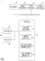
Fig. 1 is a diagram illustrating a configuration of anillumination apparatus 1 for a vehicle according to an embodiment. Theillumination apparatus 1 for a vehicle includes an image sensor 10, aforward radar sensor 16, a vehicle speed sensor 30, a steering sensor 32, a control ECU (Electronic Control Unit) 40, andhead lamps 50, as illustrated inFig. 1 . - The image sensor 10 includes a camera, which includes imaging elements such as CCDs (charge-coupled device), CMOSs (complementary metal oxide semiconductor), etc., and an image processor to recognize a state of an obstacle. The camera of the image sensor may be of a stereo type. The image sensor detects, based on an image recognition result, the information which represents a relationship between the obstacle and the host vehicle such as a relative speed, position information of the obstacle with respect to the host vehicle, for example, at a predetermined cycle. The position information of the obstacle includes information related to the position (distance) of the obstacle in the back-and-forth direction of the host vehicle, and information related to the lateral position of the obstacle in the lateral direction (width direction). The lateral position of the obstacle may be calculated based on a center position of a pixel group related to the obstacle in the lateral direction. Alternatively, the lateral position of the obstacle may be calculated as a range between a left end lateral position and a right end lateral position. The obstacle information thus obtained with the image sensor may be transmitted to the control ECU 40 at a predetermined cycle, for example. It is noted that the image processing function of the image processor (a function of calculating a position of the obstacle, for example) may be implemented by the control ECU 40. It is noted that the camera of the image sensor 10 may be a dedicated sensor for obstacle detection as described below or may be used commonly with other applications (for example, a camera for lane keeping assist, etc.). Further, the image sensor 10 may be a camera which obtains either a color image or a monochrome image.
- The
forward radar sensor 16 detects a state (obstacle information) of the obstacle in front of the host vehicle using an electric wave (millimeter wave, for example), a light wave (laser, for example) or an ultrasonic wave as a detection wave. Theforward radar sensor 16 detects information which represents a relationship between the obstacle and the host vehicle such as a relative speed, a relative distance and a direction (a lateral position) of the obstacle with respect to the host vehicle, for example, at a predetermined cycle. It is noted that if theforward radar sensor 16 is a millimeter wave radar sensor, the millimeter wave radar sensor may be of an electronic controlled scanning type, for example. In this case, the relative speed of the obstacle is detected using a Doppler frequency (frequency shift) of the electric wave, the relative distance of the obstacle is detected using a delayed time of the reflection wave, and the direction of the obstacle is detected based on a shift difference of the received waves between a plurality of reception antennas. The obstacle information thus obtained is transmitted to the control ECU 40 at a predetermined cycle. It is noted that any functions of the forward radar sensor 16 (a function of calculating a position of the obstacle, for example) may be implemented by the control ECU 40. - The vehicle speed sensor 30 outputs an electric signal according to rotation speed of vehicle wheels (vehicle speed pulses) to the control ECU 40. The steering sensor 32 outputs an electric signal according to a steering angle to the control ECU 40.
- The control ECU 40 mainly includes a microprocessor that includes a CPU, a ROM, a RAM, etc., which are interconnected via buses (not shown). The control ECU 40 includes a travel
area prediction part 42, anobstacle detection part 44, a travel area enteringdetermination part 46, and a travel areaimage formation part 48. Theparts parts - The
head lamps 50 are provided on either left and right sides of the front portion of the vehicle. Thehead lamps 50 emits visible light toward the forward scene. Thehead lamps 50 can render the image of visible light on a road surface. For this purpose, thehead lamps 50 include a projector (projecting apparatus) 52 that is capable of projecting the image, for example. Theprojectors 52 may be provided in either left orright head lamp 50. Theprojectors 52 may be implemented by high beam lamps (additional high beam lamps other than high/low combination units, for example) in either left orright head lamp 50. Theprojectors 52 have a 3-dimention rendering function based on Projection Mapping technique such that the image is superimposed on the road surface or the obstacle on the road surface. Further, theprojectors 52 may be capable of emitting the visible light other than white color to enable the rendering on the road surface in the daytime. -
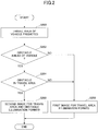
Fig. 2 is a flowchart of an example of a process executed by the control ECU 40. The process illustrated inFig. 2 may be initiated when an ignition switch of the vehicle is turned on, and then may be repeated at a predetermined cycle. Further, the process illustrated inFig. 2 may be initiated under a condition that thehead lamps 50 have been turned on. - In step S200, the travel
area prediction part 42 predicts a travel area of the vehicle after a predetermined time ΔT1 or a travel of predetermined distance D1 (represented by "after the predetermined time ΔT1", hereinafter). A way of predicting the travel area after the predetermined time or the predetermined distance travel is arbitrary. For example, the travelarea prediction part 42 may predict, based on vehicle speed information from the vehicle speed sensor 30 and steering information from the steering sensor 32, the travel area after the predetermined time ΔT1. The predetermined distance D1 may be varied according to the vehicle speed such that the predetermined distance D1 becomes greater as the vehicle speed becomes higher, or may be a fixed value. It is noted that the predetermined time ΔT1 is arbitrary; however, the predetermined time ΔT1 may be set based on a value of TTC (Time to Collision) at which a collision prevention apparatus (an automatic brake, etc.) is to be operated, for example. For example, the predetermined time ΔT1 may be the same as the value of TTC at which a collision prevention apparatus is to be operated, or slightly longer than it. - In
Fig. 3 , the travel area S on the road is schematically illustrated in a plan view. In the example illustrated inFig. 3 , the travel area S is generated based on a vehicle outline at a vehicle position V2 after the predetermined time ΔT1 with respect to the current vehicle position V1. The travel area S may circumscribe the vehicle outline at the vehicle position V2 with or without a predetermined margin. However, the travel area S may be only a part of the vehicle outline (a front portion, for example) at the vehicle position V2. Further, in the example illustrated inFig. 3 , a direction of the travel area S is constant; however, if the direction of the vehicle after the predetermined time ΔT1 will change, the direction of the travel area S may be changed accordingly. - In step S202, the
obstacle detection part 44 determines, based on the obstacle information from the image sensor 10 and/or theforward radar sensor 16, whether there is any obstacle in front of the vehicle. The obstacle to be determined is typically a stationary object, and may include an uneven spot (the uneven spot that affects the travel) on the road, a fallen stone, etc., for example. Further, the obstacle may include a stopped vehicle and a pedestrian. The pedestrian is a moving object, but its movement speed is substantially smaller than that of the vehicle. For this reason, theobstacle detection part 44 may determine whether there is any obstacle whose movement speed is less than or equal to a predetermined value. The movement speed of the obstacle may be determined based on the obstacle information from the image sensor 10 and/or theforward radar sensor 16. If the obstacle is detected in front of the vehicle, the process routine goes to step 204, otherwise the process routine goes to step 206. - In step S204, the travel area entering
determination part 46 determines whether the obstacle in front of the vehicle enters the travel area. Specifically, the travel area enteringdetermination part 46 determines whether the position of the obstacle is within the travel area predicted in step S200 described above. If it is determined that the obstacle in front of the vehicle enters the travel area, the process routine goes to step 208, otherwise the process routine goes to step 206. - In step S206, the travel area
image formation part 48 forms (renders) a first image for travel area illumination, and projects the formed first image in the travel area with theprojectors 52. The first image is arbitrary; however, the first image may be an image that merely brightens the travel area S as a whole as illustrated inFig. 3 , for example. Alternatively, the first image may be a silhouette of the vehicle (see V2 inFig. 3 ) rendered in the travel area S as illustrated inFig. 3 , for example. It is noted that lines of such a silhouette may be formed with a shade (i.e., a part in which the light is not illuminated, or a part in which the illumination strength is lower than that of a neighboring area). - In step S208, the travel area
image formation part 48 forms (renders) a second image for travel area and obstacle illumination, and projects the formed second image in the travel area with theprojectors 52. The second image for travel area and obstacle illumination is formed such that the obstacle as a whole is featured with respect to a surrounding area. InFig. 4 , a state in which thesecond image 80 according to an example is projected on the road is schematically illustrated in a plan view. In the example illustrated inFig. 4 , thesecond image 80 includes animage portion 82 for travel area illumination and animage portion 84 for obstacle illumination. In the example illustrated inFig. 4 , theimage portion 82 for travel area illumination is a portion of the rendered silhouette of the vehicle, and theimage portion 84 for obstacle illumination is a portion rendered in a checkered pattern. It is noted that black portions of the checkered pattern may be formed with shades (i.e., parts in which the light is not illuminated, or parts in which the illumination strength is lower than that of a neighboring area). Theimage portion 84 for obstacle illumination may be superimposed on theimage portion 82 for travel area illumination. In this case, the first image for travel area illumination corresponds to an image obtained by subtracting theimage portion 84 for obstacle illumination from the second image for travel area and obstacle illumination. The travel areaimage formation part 48 may repeatedly turn on and off (i.e., flash) theimage portion 84 for obstacle illumination, and may not flash (i.e., remains the turned on state of) theimage portion 82 for travel area illumination. At that time, the travel areaimage formation part 48 may implement the projection such that theimage portion 84 for obstacle illumination is superimposed on the obstacle with Projection Mapping technique and theimage portion 82 for travel area illumination is superimposed on the road surface with Projection Mapping technique. InFig. 5 , an example of a relationship between theimage portion 84 for obstacle illumination and the obstacle (the pedestrian in this example) is schematically illustrated from a view point of a driver of the vehicle. Theimage portion 84 for obstacle illumination is projected to be superimposed on the obstacle (the pedestrian in this example) as a whole, as described above. For example, a height H of the obstacle can be detected with the image sensor 10 (or the height can be predicted based on the type of the obstacle), the direction in which theimage portion 84 for obstacle illumination is to be projected may be adjusted such that the height of theimage portion 84 becomes greater than or equal to the height H at the position of the obstacle on the road. It is noted that if the obstacle exists at such a location that theimage portion 82 for travel area illumination is projected only in a part of the obstacle (foot of the pedestrian, for example) (if the obstacle on the further side starts to enter the travel area from the further side), the travel areaimage formation part 48 may move the second image for travel area and obstacle illumination as a whole to the further side such that theimage portion 84 for obstacle illumination is to be projected on the obstacle as a whole, or may project only theimage portion 84 for obstacle illumination such that theimage portion 84 is out of theimage portion 82 for travel area illumination from the further side, if possible. - According to the process illustrated in
Fig. 2 , if the obstacle enters the travel area, the second image for travel area and obstacle illumination is projected with theprojectors 52. With this arrangement, the driver can recognize the travel area after the predetermined time ΔT1, and can detect the existence of the obstacle, which enables the driver to perform operations for avoiding the obstacle, if necessary. Further, theimage portion 84 for obstacle illumination is projected to be superposed with the obstacle as a whole. Thus, if the obstacle is a human, the human can immediately recognize the approach of the vehicle. This is because a human tends to recognize the light more easily when the eyes are illuminated than when only the foot is illuminated. Further, theimage portion 84 for obstacle illumination is flashed. Thus, if the obstacle is a human, the human can immediately recognize the approach of the vehicle. Further, even for the driver, it becomes easier to recognize the existence of the obstacle, which enables the driver to immediately perform operations for avoiding the obstacle, if necessary. - All examples and conditional language recited herein are intended for pedagogical purposes to aid the reader in understanding the invention and the concepts contributed by the inventor to furthering the art, and are to be construed as being without limitation to such specifically recited examples and conditions, nor does the organization of such examples in the specification relate to a showing of the superiority and inferiority of the invention. Although the embodiment(s) of the present inventions have been described in detail, it should be understood that the various changes, substitutions, and alterations could be made hereto without departing from the spirit and scope of the invention. Further, all or part of the components of the embodiments described above can be combined.
- For example, according to the embodiment, the
image portion 84 for obstacle illumination is rendered in the checkered pattern, which enables featuring theimage portion 84 for obstacle illumination with respect to theimage portion 82 for travel area illumination, and thus enables increasing the attention attracting capability. However, only rendering the first image and the second image differently can increase the attention attracting capability. Further, a way of featuring theimage portion 84 for obstacle illumination with respect to theimage portion 82 for travel area illumination may be different. For example, the brightness of theimage portion 84 for obstacle illumination may be made higher than that of theimage portion 82 for travel area illumination. Further, the difference between theimage portion 82 for travel area illumination and theimage portion 84 for obstacle illumination may be such that only theimage portion 84 for obstacle flashes. It is noted that, even in this case, the first image and the second image differ in that the second image includes the flashingimage portion 84 for obstacle illumination. Alternatively, theimage portion 84 for obstacle illumination may be surrounded with an outer frame portion whose illuminance is enhanced, or may be formed in such color that has a high attention attracting capability, such as red, for example. - Further, according to the embodiment, the image sensor 10 and the
forward radar sensor 16 are used as an example of an obstacle detection apparatus; however, any of the image sensor 10 and theforward radar sensor 16 may be omitted. - Further, according to the embodiment, the
projectors 52 are integrally incorporated in thehead lamps 50; however, theprojectors 52 may be provided outside of thehead lamps 50. Further, theprojectors 52 may include two or more projectors which includes a first projector that projects theimage portion 82 for travel area illumination and a second projector that projects theimage portion 84 for obstacle illumination. - Further, in the embodiment described above, the
projectors 52 may be of any types. For example, theprojector 52 may be of such a projector type (mirror element projector type) that uses micro mirror elements. In this case, theprojector 52 includes a lamp as a light source, a mirror device, and a lens for imagining the light from the mirror device. The mirror device includes a number of micro mirror elements arranged therein for controlling reflection directions of the light from the lamp. The micro mirror elements in the mirror device can mechanically change inclination angles according to electrical inputs. Thus, the incident light components to the respective micro mirror elements are selectively subject to modulation (shaded, reduced, etc.,) for the reflection directions according to the inclination angles of the respective micro mirror elements that can be selectively changed. Alternatively, theprojector 52 may be of a liquid crystal projector type. In this case, theprojector 52 includes a lamp as a light source, a liquid crystal panel, and a lens for imagining the light passing through the liquid crystal panel. The liquid crystal panel includes a number of liquid crystal elements arranged therein for controlling transmission of the light from the lamp. The reflection/ transmission states of the incident light components from the light source can be changed by changing voltages applied to the respective liquid crystal elements in the liquid crystal panel. Thus, the light components from the light source can be reduced or shielded by differentiating the voltages applied to the respective liquid crystal elements. Alternatively, theprojector 52 may be of a LED matrix type. In this case, theprojectors 52 includes an LED array in which a number of LED chips are arranged and a number of lenses for imaging the light from the LED array. The light amounts of the respective LED chips can be differentiated by changing current values or current supply duration times for the respective LED chips. - Further, according to the embodiment described above, the
projectors 52 are provided in the front portion of the vehicle (i.e., theprojectors 52 are provided such that the image is projected ahead of the vehicle); however, similar projectors may be provided in a rear portion of the vehicle, in addition to or instead of theprojectors 52. Even in this case, the same function can be implemented when the vehicle travels in the back direction. - Further, according to the embodiment described above, the
image portion 84 for obstacle illumination is projected for the obstacle as a whole; however, theimage portion 84 for obstacle illumination may be projected for a part of the obstacle. For example, if the obstacle is a pedestrian, the image portion may be projected for only an upper-body of the pedestrian. Further, theimage portion 84 for obstacle illumination does not necessarily precisely correspond to the obstacle as a whole, and thus may be slightly greater than the obstacle as a whole, or may be slightly shifted in up, down, left or right direction with respect to the obstacle due to errors, etc. - The present application is based on Japanese Priority Application No.
2014-122487, filed on June 13, 2014 -
- 1
- lighting apparatus for a vehicle
- 10
- image sensor
- 16
- forward radar sensor
- 30
- vehicle speed sensor
- 32
- steering angle sensor
- 40
- control ECU
- 42
- travel area prediction part
- 44
- obstacle detection part
- 46
- travel area entering determination part
- 48
- travel area image formation part
- 50
- headlamp
- 52
- projector
- 80
- second image
Claims (4)
- An illumination apparatus for a vehicle, the illumination apparatus comprising:a projector configured to project an image of visible light;an obstacle detection apparatus configured to detect an obstacle; anda processing apparatus configured to predict a travel area of the vehicle after a predetermined time or a predetermined distance of travel, project a first image with the projector in the predicted travel area upon no obstacle in the predicted travel area being detected by the obstacle detection apparatus, and project a second image, which is different from the first image, with the projector in the predicted travel area upon the obstacle in the predicted travel area being detected by the obstacle detection apparatus.
- The illumination apparatus for a vehicle of claim 1, wherein the second image includes a first image portion and a second image portion, the first image portion being projected on an area related to the obstacle as a whole in the travel area, the second image portion being projected on another area in the travel area.
- The illumination apparatus for a vehicle of claim 2, wherein the second image includes the first image portion that flashes and the second image portion that does not flash.
- The illumination apparatus for a vehicle of claim 2 or 3, wherein the first image portion is brighter than the second image portion.
Applications Claiming Priority (2)
| Application Number | Priority Date | Filing Date | Title |
|---|---|---|---|
| JP2014122487A JP6075331B2 (en) | 2014-06-13 | 2014-06-13 | Vehicle lighting device |
| PCT/JP2015/065368 WO2015190299A1 (en) | 2014-06-13 | 2015-05-28 | Vehicular lighting device |
Publications (3)
| Publication Number | Publication Date |
|---|---|
| EP3156283A1 true EP3156283A1 (en) | 2017-04-19 |
| EP3156283A4 EP3156283A4 (en) | 2017-08-09 |
| EP3156283B1 EP3156283B1 (en) | 2022-04-06 |
Family
ID=54833401
Family Applications (1)
| Application Number | Title | Priority Date | Filing Date |
|---|---|---|---|
| EP15807479.9A Active EP3156283B1 (en) | 2014-06-13 | 2015-05-28 | Illumination appartus for vehicle |
Country Status (5)
| Country | Link |
|---|---|
| US (1) | US10239440B2 (en) |
| EP (1) | EP3156283B1 (en) |
| JP (1) | JP6075331B2 (en) |
| CN (1) | CN106458084B (en) |
| WO (1) | WO2015190299A1 (en) |
Cited By (1)
| Publication number | Priority date | Publication date | Assignee | Title |
|---|---|---|---|---|
| EP3699029A4 (en) * | 2017-10-19 | 2021-07-07 | Koito Manufacturing Co., Ltd. | Vehicle lamp system |
Families Citing this family (13)
| Publication number | Priority date | Publication date | Assignee | Title |
|---|---|---|---|---|
| JP6075331B2 (en) | 2014-06-13 | 2017-02-08 | トヨタ自動車株式会社 | Vehicle lighting device |
| JP6112072B2 (en) * | 2014-06-19 | 2017-04-12 | トヨタ自動車株式会社 | Vehicle lighting device |
| KR101825687B1 (en) * | 2015-04-24 | 2018-02-05 | 한국전자통신연구원 | The obstacle detection appratus and method using difference image |
| JP6447545B2 (en) | 2016-03-11 | 2019-01-09 | トヨタ自動車株式会社 | Vehicle lighting device |
| DE102016003296A1 (en) * | 2016-03-17 | 2017-09-21 | Audi Ag | Motor vehicle with at least one headlight |
| JP6305456B2 (en) * | 2016-03-31 | 2018-04-04 | 株式会社Subaru | Display device |
| JP6595401B2 (en) | 2016-04-26 | 2019-10-23 | 株式会社Soken | Display control device |
| CN110401825A (en) * | 2018-04-24 | 2019-11-01 | 长城汽车股份有限公司 | Vehicle projecting method and device |
| DE102018212274A1 (en) * | 2018-07-24 | 2020-01-30 | Bayerische Motoren Werke Aktiengesellschaft | Method for operating a lighting device in a motor vehicle |
| KR102619558B1 (en) * | 2018-11-16 | 2024-01-02 | 현대모비스 주식회사 | Control system of autonomous vehicle and control method thereof |
| WO2020218498A1 (en) * | 2019-04-25 | 2020-10-29 | 株式会社小糸製作所 | Sensing system and vehicle |
| KR20210136567A (en) * | 2020-05-08 | 2021-11-17 | 현대자동차주식회사 | Communication lighting system of vehicle |
| DE102020118914A1 (en) | 2020-07-17 | 2022-01-20 | Audi Aktiengesellschaft | Method for illuminating a user's trajectory, controller, display device, and wearable accessory |
Family Cites Families (53)
| Publication number | Priority date | Publication date | Assignee | Title |
|---|---|---|---|---|
| SU1277172A1 (en) | 1984-12-10 | 1986-12-15 | Войсковая Часть 25840 | Device for training vehicle drivers |
| JP4114292B2 (en) * | 1998-12-03 | 2008-07-09 | アイシン・エィ・ダブリュ株式会社 | Driving support device |
| DE10034381C2 (en) | 2000-07-14 | 2002-05-29 | Audi Ag | Information display device for vehicles |
| ATE311725T1 (en) * | 2001-09-07 | 2005-12-15 | Matsushita Electric Ind Co Ltd | DEVICE FOR DISPLAYING THE SURROUNDINGS OF A VEHICLE AND SYSTEM FOR PROVIDING IMAGE |
| JP4161584B2 (en) | 2002-02-07 | 2008-10-08 | トヨタ自動車株式会社 | Safety device for moving objects |
| JP4092956B2 (en) | 2002-06-05 | 2008-05-28 | トヨタ自動車株式会社 | In-vehicle driving support device |
| JP4059079B2 (en) | 2002-12-27 | 2008-03-12 | 市光工業株式会社 | Digital lighting device for vehicle, digital display device for vehicle, and information display method |
| US20060125616A1 (en) | 2004-11-29 | 2006-06-15 | Song Won M | Method for a changing safety signaling system |
| JP2007180803A (en) * | 2005-12-27 | 2007-07-12 | Aisin Aw Co Ltd | Method and device for supporting driving |
| ITBO20060282A1 (en) | 2006-04-13 | 2007-10-14 | Ferrari Spa | METHOD AND SITEMA OF HELP FOR A ROAD VEHICLE |
| DE102006050547A1 (en) | 2006-10-26 | 2008-04-30 | Bayerische Motoren Werke Ag | Method for displaying information |
| DE102006050550A1 (en) | 2006-10-26 | 2008-04-30 | Bayerische Motoren Werke Ag | Method for controlling a driving maneuver |
| JP4720764B2 (en) * | 2006-11-16 | 2011-07-13 | 株式会社デンソー | Headlight control device |
| JP2008174192A (en) | 2007-01-22 | 2008-07-31 | Aisin Aw Co Ltd | Parking support method and parking support device |
| US20080198372A1 (en) | 2007-02-21 | 2008-08-21 | Spatial Photonics, Inc. | Vehicle headlight with image display |
| JP2009001164A (en) | 2007-06-21 | 2009-01-08 | Aisin Aw Co Ltd | Driving assisting device, driving assisting method, and driving assisting program |
| JP5151452B2 (en) * | 2007-12-19 | 2013-02-27 | 株式会社豊田中央研究所 | Information display device |
| JP5108605B2 (en) * | 2008-04-23 | 2012-12-26 | 三洋電機株式会社 | Driving support system and vehicle |
| JP2010026759A (en) * | 2008-07-18 | 2010-02-04 | Mazda Motor Corp | Driving support device for vehicle |
| WO2011161177A1 (en) | 2010-06-23 | 2011-12-29 | Continental Teves Ag & Co. Ohg | Method and system for validating information |
| DE102010034853A1 (en) | 2010-08-18 | 2012-02-23 | Gm Global Technology Operations Llc (N.D.Ges.D. Staates Delaware) | Motor vehicle with digital projectors |
| CN101973229B (en) * | 2010-10-30 | 2012-10-24 | 奇瑞汽车股份有限公司 | Self-adaptive rampway auxiliary lighting device and method |
| FR2967625B1 (en) | 2010-11-22 | 2012-11-09 | Peugeot Citroen Automobiles Sa | VEHICLE COMPRISING A LIGHT SOURCE FOR PROJECTION OF INFORMATION ON THE SOIL BEFORE THE VEHICLE |
| DE102011081382A1 (en) * | 2011-08-23 | 2013-02-28 | Robert Bosch Gmbh | Method and device for changing a light emission of at least one headlight of a vehicle |
| DE102011081396B4 (en) | 2011-08-23 | 2020-12-03 | Robert Bosch Gmbh | Method and control device for adapting a radiation characteristic of at least one headlight |
| DE102011112577A1 (en) | 2011-09-08 | 2013-03-14 | Continental Teves Ag & Co. Ohg | Method and device for an assistance system in a vehicle for carrying out an autonomous or semi-autonomous driving maneuver |
| US9019347B2 (en) * | 2011-10-13 | 2015-04-28 | Aisin Seiki Kabushiki Kaisha | Image generator |
| JP2013097885A (en) * | 2011-10-28 | 2013-05-20 | Seiko Epson Corp | Headlight device and headlight system |
| KR20130052425A (en) * | 2011-11-11 | 2013-05-22 | 현대자동차주식회사 | Head lamp system |
| KR101288069B1 (en) * | 2011-11-14 | 2013-07-18 | 현대모비스 주식회사 | Parking assistance system using projector and method thereof |
| JP2013103628A (en) | 2011-11-15 | 2013-05-30 | Seiko Epson Corp | Determination support device and determination support method |
| DE102011119923A1 (en) | 2011-11-28 | 2013-05-29 | Son Hao Vu | Lighting system for air- and land vehicles and working machines for projection of targeted optical guidance or patterns during operation, has integrated control unit which assembles and monitors necessary data for desired operating mode |
| JP5794134B2 (en) | 2011-12-15 | 2015-10-14 | セイコーエプソン株式会社 | Detection apparatus and detection method |
| JP5831302B2 (en) * | 2012-03-08 | 2015-12-09 | トヨタ自動車株式会社 | Multi-light headlight |
| JP2013203251A (en) * | 2012-03-28 | 2013-10-07 | Denso Corp | Light emission control device, emission warning system, light control system, and light emission control program |
| JP5949085B2 (en) | 2012-04-20 | 2016-07-06 | 市光工業株式会社 | Light distribution control system for vehicle headlamps |
| JP2014013524A (en) | 2012-07-05 | 2014-01-23 | Mitsubishi Motors Corp | Vehicle notification device |
| DE102012013602A1 (en) | 2012-07-07 | 2014-04-10 | Volkswagen Aktiengesellschaft | Signaling of an emergency stop method of a motor vehicle |
| US8733939B2 (en) | 2012-07-26 | 2014-05-27 | Cloudcar, Inc. | Vehicle content projection |
| JP5934612B2 (en) | 2012-08-23 | 2016-06-15 | スタンレー電気株式会社 | Lighting control device for vehicle headlamp, vehicle headlamp system |
| JP5992278B2 (en) * | 2012-09-20 | 2016-09-14 | スタンレー電気株式会社 | Lighting control device for vehicle headlamp, vehicle headlamp system |
| WO2014076769A1 (en) * | 2012-11-13 | 2014-05-22 | 株式会社東芝 | Detection device, method, and program |
| US20140267415A1 (en) | 2013-03-12 | 2014-09-18 | Xueming Tang | Road marking illuminattion system and method |
| DE102013013867A1 (en) | 2013-08-20 | 2015-03-12 | Audi Ag | Motor vehicle and method for controlling a motor vehicle |
| US20150066284A1 (en) | 2013-09-05 | 2015-03-05 | Ford Global Technologies, Llc | Autonomous vehicle control for impaired driver |
| US9364178B2 (en) | 2013-11-26 | 2016-06-14 | Elwha Llc | Robotic vehicle control |
| US9481287B2 (en) | 2014-01-21 | 2016-11-01 | Harman International Industries, Inc. | Roadway projection system |
| JP6264909B2 (en) * | 2014-01-31 | 2018-01-24 | 株式会社デンソー | Headlamp control device and headlamp |
| US9349293B2 (en) | 2014-02-07 | 2016-05-24 | Here Global B.V | Method and apparatus for providing vehicle synchronization to facilitate a crossing |
| JP6395393B2 (en) | 2014-02-13 | 2018-09-26 | 株式会社小糸製作所 | Vehicle driving support device |
| DE102014204002A1 (en) | 2014-03-05 | 2015-09-10 | Conti Temic Microelectronic Gmbh | A method of identifying a projected icon on a road in a vehicle, device and vehicle |
| US9475422B2 (en) | 2014-05-22 | 2016-10-25 | Applied Invention, Llc | Communication between autonomous vehicle and external observers |
| JP6075331B2 (en) | 2014-06-13 | 2017-02-08 | トヨタ自動車株式会社 | Vehicle lighting device |
-
2014
- 2014-06-13 JP JP2014122487A patent/JP6075331B2/en active Active
-
2015
- 2015-05-28 US US15/316,629 patent/US10239440B2/en not_active Expired - Fee Related
- 2015-05-28 EP EP15807479.9A patent/EP3156283B1/en active Active
- 2015-05-28 WO PCT/JP2015/065368 patent/WO2015190299A1/en active Application Filing
- 2015-05-28 CN CN201580030566.1A patent/CN106458084B/en active Active
Cited By (2)
| Publication number | Priority date | Publication date | Assignee | Title |
|---|---|---|---|---|
| EP3699029A4 (en) * | 2017-10-19 | 2021-07-07 | Koito Manufacturing Co., Ltd. | Vehicle lamp system |
| US11180072B2 (en) | 2017-10-19 | 2021-11-23 | Koito Manufacturing Co., Ltd. | Vehicle lamp system that simultaneously turns on a territory lamp and a stop lamp in response to detected third party on projected course of vehicle |
Also Published As
| Publication number | Publication date |
|---|---|
| JP2016002802A (en) | 2016-01-12 |
| JP6075331B2 (en) | 2017-02-08 |
| EP3156283A4 (en) | 2017-08-09 |
| CN106458084B (en) | 2018-12-28 |
| CN106458084A (en) | 2017-02-22 |
| WO2015190299A1 (en) | 2015-12-17 |
| US10239440B2 (en) | 2019-03-26 |
| US20170144584A1 (en) | 2017-05-25 |
| EP3156283B1 (en) | 2022-04-06 |
Similar Documents
| Publication | Publication Date | Title |
|---|---|---|
| US10239440B2 (en) | Illumination apparatus for vehicle | |
| JP6453669B2 (en) | Vehicle headlamp control device | |
| JP5617999B2 (en) | On-vehicle peripheral object recognition device and driving support device using the same | |
| JP5680573B2 (en) | Vehicle driving environment recognition device | |
| US10189402B2 (en) | Illumination apparatus for vehicle | |
| JP5779028B2 (en) | Light distribution control means for headlamp | |
| JP5761002B2 (en) | Lighting control device | |
| JP6311768B1 (en) | Vehicle headlight control device | |
| US20140355280A1 (en) | Light distribution control system for vehicle | |
| US9187027B2 (en) | Vehicle headlight | |
| US9278643B2 (en) | Vehicle headlight light distribution pattern | |
| JP2019077204A (en) | Vehicular lamp fitting system, control device of vehicular lamp fitting, and control method of vehicular lamp fitting | |
| US10730427B2 (en) | Lighting device | |
| JP6409847B2 (en) | Vehicle headlight control device | |
| WO2013137324A1 (en) | Vehicle-mounted illumination device | |
| JP6332402B2 (en) | Vehicle headlight control device and vehicle with headlight | |
| JP6278217B1 (en) | Vehicle headlight control device | |
| JP6663770B2 (en) | Vehicle light distribution control device | |
| JP6125900B2 (en) | Rear fog lamp control device and rear fog lamp system |
Legal Events
| Date | Code | Title | Description |
|---|---|---|---|
| STAA | Information on the status of an ep patent application or granted ep patent |
Free format text: STATUS: THE INTERNATIONAL PUBLICATION HAS BEEN MADE |
|
| PUAI | Public reference made under article 153(3) epc to a published international application that has entered the european phase |
Free format text: ORIGINAL CODE: 0009012 |
|
| STAA | Information on the status of an ep patent application or granted ep patent |
Free format text: STATUS: REQUEST FOR EXAMINATION WAS MADE |
|
| 17P | Request for examination filed |
Effective date: 20161205 |
|
| AK | Designated contracting states |
Kind code of ref document: A1 Designated state(s): AL AT BE BG CH CY CZ DE DK EE ES FI FR GB GR HR HU IE IS IT LI LT LU LV MC MK MT NL NO PL PT RO RS SE SI SK SM TR |
|
| AX | Request for extension of the european patent |
Extension state: BA ME |
|
| REG | Reference to a national code |
Ref country code: DE Ref legal event code: R079 Ref document number: 602015078076 Country of ref document: DE Free format text: PREVIOUS MAIN CLASS: B60Q0001240000 Ipc: B60Q0001520000 |
|
| RIC1 | Information provided on ipc code assigned before grant |
Ipc: B60Q 1/52 20060101AFI20170628BHEP |
|
| A4 | Supplementary search report drawn up and despatched |
Effective date: 20170706 |
|
| DAV | Request for validation of the european patent (deleted) | ||
| DAX | Request for extension of the european patent (deleted) | ||
| STAA | Information on the status of an ep patent application or granted ep patent |
Free format text: STATUS: EXAMINATION IS IN PROGRESS |
|
| 17Q | First examination report despatched |
Effective date: 20200421 |
|
| STAA | Information on the status of an ep patent application or granted ep patent |
Free format text: STATUS: EXAMINATION IS IN PROGRESS |
|
| STAA | Information on the status of an ep patent application or granted ep patent |
Free format text: STATUS: EXAMINATION IS IN PROGRESS |
|
| GRAP | Despatch of communication of intention to grant a patent |
Free format text: ORIGINAL CODE: EPIDOSNIGR1 |
|
| STAA | Information on the status of an ep patent application or granted ep patent |
Free format text: STATUS: GRANT OF PATENT IS INTENDED |
|
| INTG | Intention to grant announced |
Effective date: 20211216 |
|
| GRAS | Grant fee paid |
Free format text: ORIGINAL CODE: EPIDOSNIGR3 |
|
| GRAA | (expected) grant |
Free format text: ORIGINAL CODE: 0009210 |
|
| STAA | Information on the status of an ep patent application or granted ep patent |
Free format text: STATUS: THE PATENT HAS BEEN GRANTED |
|
| AK | Designated contracting states |
Kind code of ref document: B1 Designated state(s): AL AT BE BG CH CY CZ DE DK EE ES FI FR GB GR HR HU IE IS IT LI LT LU LV MC MK MT NL NO PL PT RO RS SE SI SK SM TR |
|
| REG | Reference to a national code |
Ref country code: GB Ref legal event code: FG4D |
|
| REG | Reference to a national code |
Ref country code: CH Ref legal event code: EP |
|
| REG | Reference to a national code |
Ref country code: AT Ref legal event code: REF Ref document number: 1481055 Country of ref document: AT Kind code of ref document: T Effective date: 20220415 |
|
| REG | Reference to a national code |
Ref country code: DE Ref legal event code: R096 Ref document number: 602015078076 Country of ref document: DE |
|
| REG | Reference to a national code |
Ref country code: IE Ref legal event code: FG4D |
|
| REG | Reference to a national code |
Ref country code: LT Ref legal event code: MG9D |
|
| PGFP | Annual fee paid to national office [announced via postgrant information from national office to epo] |
Ref country code: DE Payment date: 20220511 Year of fee payment: 8 |
|
| REG | Reference to a national code |
Ref country code: NL Ref legal event code: MP Effective date: 20220406 |
|
| REG | Reference to a national code |
Ref country code: AT Ref legal event code: MK05 Ref document number: 1481055 Country of ref document: AT Kind code of ref document: T Effective date: 20220406 |
|
| PG25 | Lapsed in a contracting state [announced via postgrant information from national office to epo] |
Ref country code: NL Free format text: LAPSE BECAUSE OF FAILURE TO SUBMIT A TRANSLATION OF THE DESCRIPTION OR TO PAY THE FEE WITHIN THE PRESCRIBED TIME-LIMIT Effective date: 20220406 |
|
| PG25 | Lapsed in a contracting state [announced via postgrant information from national office to epo] |
Ref country code: SE Free format text: LAPSE BECAUSE OF FAILURE TO SUBMIT A TRANSLATION OF THE DESCRIPTION OR TO PAY THE FEE WITHIN THE PRESCRIBED TIME-LIMIT Effective date: 20220406 Ref country code: PT Free format text: LAPSE BECAUSE OF FAILURE TO SUBMIT A TRANSLATION OF THE DESCRIPTION OR TO PAY THE FEE WITHIN THE PRESCRIBED TIME-LIMIT Effective date: 20220808 Ref country code: NO Free format text: LAPSE BECAUSE OF FAILURE TO SUBMIT A TRANSLATION OF THE DESCRIPTION OR TO PAY THE FEE WITHIN THE PRESCRIBED TIME-LIMIT Effective date: 20220706 Ref country code: LT Free format text: LAPSE BECAUSE OF FAILURE TO SUBMIT A TRANSLATION OF THE DESCRIPTION OR TO PAY THE FEE WITHIN THE PRESCRIBED TIME-LIMIT Effective date: 20220406 Ref country code: HR Free format text: LAPSE BECAUSE OF FAILURE TO SUBMIT A TRANSLATION OF THE DESCRIPTION OR TO PAY THE FEE WITHIN THE PRESCRIBED TIME-LIMIT Effective date: 20220406 Ref country code: GR Free format text: LAPSE BECAUSE OF FAILURE TO SUBMIT A TRANSLATION OF THE DESCRIPTION OR TO PAY THE FEE WITHIN THE PRESCRIBED TIME-LIMIT Effective date: 20220707 Ref country code: FI Free format text: LAPSE BECAUSE OF FAILURE TO SUBMIT A TRANSLATION OF THE DESCRIPTION OR TO PAY THE FEE WITHIN THE PRESCRIBED TIME-LIMIT Effective date: 20220406 Ref country code: ES Free format text: LAPSE BECAUSE OF FAILURE TO SUBMIT A TRANSLATION OF THE DESCRIPTION OR TO PAY THE FEE WITHIN THE PRESCRIBED TIME-LIMIT Effective date: 20220406 Ref country code: BG Free format text: LAPSE BECAUSE OF FAILURE TO SUBMIT A TRANSLATION OF THE DESCRIPTION OR TO PAY THE FEE WITHIN THE PRESCRIBED TIME-LIMIT Effective date: 20220706 Ref country code: AT Free format text: LAPSE BECAUSE OF FAILURE TO SUBMIT A TRANSLATION OF THE DESCRIPTION OR TO PAY THE FEE WITHIN THE PRESCRIBED TIME-LIMIT Effective date: 20220406 |
|
| PG25 | Lapsed in a contracting state [announced via postgrant information from national office to epo] |
Ref country code: RS Free format text: LAPSE BECAUSE OF FAILURE TO SUBMIT A TRANSLATION OF THE DESCRIPTION OR TO PAY THE FEE WITHIN THE PRESCRIBED TIME-LIMIT Effective date: 20220406 Ref country code: PL Free format text: LAPSE BECAUSE OF FAILURE TO SUBMIT A TRANSLATION OF THE DESCRIPTION OR TO PAY THE FEE WITHIN THE PRESCRIBED TIME-LIMIT Effective date: 20220406 Ref country code: LV Free format text: LAPSE BECAUSE OF FAILURE TO SUBMIT A TRANSLATION OF THE DESCRIPTION OR TO PAY THE FEE WITHIN THE PRESCRIBED TIME-LIMIT Effective date: 20220406 Ref country code: IS Free format text: LAPSE BECAUSE OF FAILURE TO SUBMIT A TRANSLATION OF THE DESCRIPTION OR TO PAY THE FEE WITHIN THE PRESCRIBED TIME-LIMIT Effective date: 20220806 |
|
| REG | Reference to a national code |
Ref country code: CH Ref legal event code: PL |
|
| REG | Reference to a national code |
Ref country code: DE Ref legal event code: R097 Ref document number: 602015078076 Country of ref document: DE |
|
| REG | Reference to a national code |
Ref country code: BE Ref legal event code: MM Effective date: 20220531 |
|
| PG25 | Lapsed in a contracting state [announced via postgrant information from national office to epo] |
Ref country code: SM Free format text: LAPSE BECAUSE OF FAILURE TO SUBMIT A TRANSLATION OF THE DESCRIPTION OR TO PAY THE FEE WITHIN THE PRESCRIBED TIME-LIMIT Effective date: 20220406 Ref country code: SK Free format text: LAPSE BECAUSE OF FAILURE TO SUBMIT A TRANSLATION OF THE DESCRIPTION OR TO PAY THE FEE WITHIN THE PRESCRIBED TIME-LIMIT Effective date: 20220406 Ref country code: RO Free format text: LAPSE BECAUSE OF FAILURE TO SUBMIT A TRANSLATION OF THE DESCRIPTION OR TO PAY THE FEE WITHIN THE PRESCRIBED TIME-LIMIT Effective date: 20220406 Ref country code: MC Free format text: LAPSE BECAUSE OF FAILURE TO SUBMIT A TRANSLATION OF THE DESCRIPTION OR TO PAY THE FEE WITHIN THE PRESCRIBED TIME-LIMIT Effective date: 20220406 Ref country code: LU Free format text: LAPSE BECAUSE OF NON-PAYMENT OF DUE FEES Effective date: 20220528 Ref country code: LI Free format text: LAPSE BECAUSE OF NON-PAYMENT OF DUE FEES Effective date: 20220531 Ref country code: EE Free format text: LAPSE BECAUSE OF FAILURE TO SUBMIT A TRANSLATION OF THE DESCRIPTION OR TO PAY THE FEE WITHIN THE PRESCRIBED TIME-LIMIT Effective date: 20220406 Ref country code: DK Free format text: LAPSE BECAUSE OF FAILURE TO SUBMIT A TRANSLATION OF THE DESCRIPTION OR TO PAY THE FEE WITHIN THE PRESCRIBED TIME-LIMIT Effective date: 20220406 Ref country code: CZ Free format text: LAPSE BECAUSE OF FAILURE TO SUBMIT A TRANSLATION OF THE DESCRIPTION OR TO PAY THE FEE WITHIN THE PRESCRIBED TIME-LIMIT Effective date: 20220406 Ref country code: CH Free format text: LAPSE BECAUSE OF NON-PAYMENT OF DUE FEES Effective date: 20220531 |
|
| PLBE | No opposition filed within time limit |
Free format text: ORIGINAL CODE: 0009261 |
|
| STAA | Information on the status of an ep patent application or granted ep patent |
Free format text: STATUS: NO OPPOSITION FILED WITHIN TIME LIMIT |
|
| 26N | No opposition filed |
Effective date: 20230110 |
|
| GBPC | Gb: european patent ceased through non-payment of renewal fee |
Effective date: 20220706 |
|
| PG25 | Lapsed in a contracting state [announced via postgrant information from national office to epo] |
Ref country code: AL Free format text: LAPSE BECAUSE OF FAILURE TO SUBMIT A TRANSLATION OF THE DESCRIPTION OR TO PAY THE FEE WITHIN THE PRESCRIBED TIME-LIMIT Effective date: 20220406 |
|
| PG25 | Lapsed in a contracting state [announced via postgrant information from national office to epo] |
Ref country code: IE Free format text: LAPSE BECAUSE OF NON-PAYMENT OF DUE FEES Effective date: 20220528 Ref country code: FR Free format text: LAPSE BECAUSE OF NON-PAYMENT OF DUE FEES Effective date: 20220606 |
|
| PG25 | Lapsed in a contracting state [announced via postgrant information from national office to epo] |
Ref country code: SI Free format text: LAPSE BECAUSE OF FAILURE TO SUBMIT A TRANSLATION OF THE DESCRIPTION OR TO PAY THE FEE WITHIN THE PRESCRIBED TIME-LIMIT Effective date: 20220406 Ref country code: GB Free format text: LAPSE BECAUSE OF NON-PAYMENT OF DUE FEES Effective date: 20220706 Ref country code: BE Free format text: LAPSE BECAUSE OF NON-PAYMENT OF DUE FEES Effective date: 20220531 |
|
| P01 | Opt-out of the competence of the unified patent court (upc) registered |
Effective date: 20230427 |
|
| REG | Reference to a national code |
Ref country code: DE Ref legal event code: R119 Ref document number: 602015078076 Country of ref document: DE |
|
| PG25 | Lapsed in a contracting state [announced via postgrant information from national office to epo] |
Ref country code: IT Free format text: LAPSE BECAUSE OF FAILURE TO SUBMIT A TRANSLATION OF THE DESCRIPTION OR TO PAY THE FEE WITHIN THE PRESCRIBED TIME-LIMIT Effective date: 20220406 |
|
| PG25 | Lapsed in a contracting state [announced via postgrant information from national office to epo] |
Ref country code: HU Free format text: LAPSE BECAUSE OF FAILURE TO SUBMIT A TRANSLATION OF THE DESCRIPTION OR TO PAY THE FEE WITHIN THE PRESCRIBED TIME-LIMIT; INVALID AB INITIO Effective date: 20150528 |