EP3156267A1 - Machine de détalonnage d'un pneu d'une roue - Google Patents
Machine de détalonnage d'un pneu d'une roue Download PDFInfo
- Publication number
- EP3156267A1 EP3156267A1 EP15002898.3A EP15002898A EP3156267A1 EP 3156267 A1 EP3156267 A1 EP 3156267A1 EP 15002898 A EP15002898 A EP 15002898A EP 3156267 A1 EP3156267 A1 EP 3156267A1
- Authority
- EP
- European Patent Office
- Prior art keywords
- tool
- frame
- damper
- machine
- tire
- Prior art date
- Legal status (The legal status is an assumption and is not a legal conclusion. Google has not performed a legal analysis and makes no representation as to the accuracy of the status listed.)
- Granted
Links
Images


Classifications
-
- B—PERFORMING OPERATIONS; TRANSPORTING
- B60—VEHICLES IN GENERAL
- B60C—VEHICLE TYRES; TYRE INFLATION; TYRE CHANGING; CONNECTING VALVES TO INFLATABLE ELASTIC BODIES IN GENERAL; DEVICES OR ARRANGEMENTS RELATED TO TYRES
- B60C25/00—Apparatus or tools adapted for mounting, removing or inspecting tyres
- B60C25/01—Apparatus or tools adapted for mounting, removing or inspecting tyres for removing tyres from or mounting tyres on wheels
- B60C25/05—Machines
- B60C25/125—Machines for only breaking the beads
- B60C25/13—Machines for only breaking the beads acting axially on a part of the bead or side wall only at localised regions of the bead or side wall
-
- B—PERFORMING OPERATIONS; TRANSPORTING
- B60—VEHICLES IN GENERAL
- B60C—VEHICLE TYRES; TYRE INFLATION; TYRE CHANGING; CONNECTING VALVES TO INFLATABLE ELASTIC BODIES IN GENERAL; DEVICES OR ARRANGEMENTS RELATED TO TYRES
- B60C25/00—Apparatus or tools adapted for mounting, removing or inspecting tyres
- B60C25/01—Apparatus or tools adapted for mounting, removing or inspecting tyres for removing tyres from or mounting tyres on wheels
- B60C25/05—Machines
- B60C25/0563—Tools interacting with the tyre and moved in relation to the tyre during operation
- B60C25/0572—Tools interacting with the tyre and moved in relation to the tyre during operation pressing only
Definitions
- the invention relates to the field of machines for offsetting a tire of a wheel, an operation which is necessary prior to the actual disassembly of the tire.
- the invention also relates to a machine for mounting and dismounting a tire including a tire machine or device.
- Machines for offsetting a tire of a wheel are well known, for example from the US patent US 3,780,785 .
- the wheel is placed on a horizontal support plate which is mounted on an upper face of a frame.
- the off-set tool (sometimes also referred to as a "shovel") is mounted to a vertical column that can move downwardly in a guided manner to bring the tire tool closer to the tire and then push the tire bead downward. so that the heel comes off the rim.
- the column consists of the cylinder of a hydraulic cylinder whose piston is connected to the frame of the machine via a piston rod. By actuating said cylinder, the tool will move vertically downwards and in force, which will bring the tool into its working stroke.
- An object of the invention is to provide a machine for offsetting a tire of a wheel rim which is less expensive than known machines.
- a pneumatic actuator is indeed cheaper and requires less maintenance than a double-acting hydraulic cylinder.
- a pneumatic actuator requires compressed air to operate, compressed air sources are usually already available on site, even if the tire is not inflated after assembly, so it is not necessary for the machine has a compressor, which reduces the cost again. It is sufficient to provide a simple pneumatic connection for connecting the pneumatic actuator to said source of compressed air.
- the presence of the damper furthermore makes it possible to damp the movement of the tool-holder structure, in particular at the moment when the tire bead comes off the rim as well as after the calibration has occurred, which reduces the shocks and vibrations that would otherwise occur when the resistance offered by the tire collapses as a result of the tire being trimmed.
- the combination of the pneumatic actuator and the shock absorber thus makes it possible to reduce overall the cost of the machine, while reducing the magnitude of the shocks and vibrations at the time of the relief and thus the wear of the parts and / or the fatigue of the materials.
- the damper is a telescopic damper whose cylinder is connected to the tool-carrying structure or to the frame and whose piston is connected respectively to the frame or to the tool-holder structure via a piston rod. More preferably, the damper is a hydraulic damper. Such dampers are indeed widely available commercially and relatively inexpensive.
- the actuator is an inflatable air cushion, one face of which is connected to or abuts on the frame, and an opposite face of which is connected to or abuts on the tool support structure, said air cushion comprising at least one compressed air inlet.
- Inflatable air bags are indeed widely available commercially and relatively inexpensive. It can for example be inflatable air cushions commonly used as shock absorbers in trucks.
- the support plate forms an angle between 0 ° and 10 ° relative to a horizontal plane
- the tool-carrying structure comprises a column mounted in linear translation guided relative to the frame
- the actuator is configured to put the tool-carrier structure in motion according to said linear translation.
- the axis of the cylinder of the damper is parallel or merged with the axis of the column, which allows the use of simple mechanical connections as well as to better dampen shocks.
- the damper cylinder is connected to the frame and the damper piston is connected to the tool carrier structure via the piston rod.
- the opening of the cylinder, through which the piston rod exits, will be above the piston and the risk of hydraulic fluid leakage will be limited. The damper will thus require less maintenance.
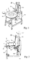
- the Fig.1 shows a perspective view of an example of a machine according to the invention.
- This machine comprises a frame (40), designed to rest on the ground, said frame (40) being surmounted by a support plate (50) to support a lateral side of a wheel (1).
- the support plate (50) forms an angle between 0 ° and 10 ° with respect to a horizontal plane.
- the support plate (50) Opposite the support plate (50) is a relief tool (70) (sometimes called “shovel") which serves to take off the tire (2) of the wheel (1).
- a relief tool (70) (sometimes called “shovel") which serves to take off the tire (2) of the wheel (1).
- the uncalibration tool (70) is mounted to a tool carrier (80).
- Said tool carrier structure (80) is movably mounted to the frame (40) so as to move the tool to or away from a sidewall (24) of the tire (2).
- the tool-carrying structure (80) comprises a column (81) mounted in linear translation guided relative to the frame (40).
- the translation axis will preferably be offset from the vertical an angle ⁇ (alpha) between 0 and 15 °, as seen best at Figs.2 and 3 . This has the effect of facilitating the relief of the tire (2).
- an angular movement can be used instead of using a linear translational movement .
- the tool holder structure (80) may for example be mounted to the frame (40) by means of a horizontal axis pivot.
- the tool (70) is, in this example, mounted at a distal end of a tube which is encased in a sleeve forming part of the tool holder structure (80).
- the tube and the sleeve are pierced with holes that can be faced, which allows to fix the tube to the sleeve, for example by means of a pin, and at different heights relative to the support plate (50), this in order to accommodate different widths of rims.
- the machine also comprises an actuator (90) connected to the frame (40) on the one hand and to the tool holder structure (80) on the other hand.
- This actuator (90) is configured to move the tool carrier (80) to move the relief tool (70) to the backing plate (50).
- the actuator (90) is configured to move the tool-carrying structure (80) in a linear translation, as indicated by an arrow on the Fig.1 .
- said actuator (90) is a pneumatic actuator. More details on this actuator (90) will be provided in connection with the Fig. 4 .
- the machine further comprises a damper (100) mounted between the tool carrier (80) and the frame (40).
- This damper (100) damps the movement of the tool holder structure (80) relative to the frame (40) when said tool holder structure (80) is moved by the actuator (90). More details on this buffer (100) will be provided in connection with the Figs.5 and 6 .
- the Fig.2 shows a profile view of the machine from the Fig.1 when the tool carrier structure (80) is in the rest position, that is, when the tool carrier structure (80), and thus the relief tool (70), is in a raised position to allow an operator to place the wheel (1) on the support plate (50) without being disturbed by the tool. In this rest position, neither the actuator (90) nor the damper (100) are active.
- the Fig.3 shows a profile view of the machine from the Fig.1 in the end-of-work position, that is to say when the tool-carrying structure (80), and therefore the recalibration tool (70), is in a low position after the tire has been trimmed (2).
- the Fig.4 shows a detailed view of a part of the machine from the Fig.1 . It shows the actuator (90) and the damper (100) and how these two elements are connected to the frame (40) and the tool holder structure (80).
- the actuator (90) is an inflatable air cushion, one face (91) of which is connected to - or abuts on the frame (40), and an opposite face (92) of which is connected to - or abuts on the tool holder structure (80).
- the tool-carrying structure (80) comprises a stop (80a) on which the opposite face of the air cushion (90) abuts, but it goes without saying that many other embodiments are possible.
- the air cushion (90) has a compressed air inlet (95) for inflating it by connecting the compressed air inlet (95) to a source of compressed air via a controllable valve. By opening this valve, the air cushion will inflate and force down the tool support structure (80), and thus the relief tool (70), towards the side (24) of the tire (2) for Relieving. Said valve will also have an exhaust position for releasing the pressure in the air cushion when the tire is trimmed. Said valve may for example be a three-way valve. On the Fig.4 , the air cushion is shown inflated.
- the air cushion (90) is dimensioned to be able to exert a force on the movable structure which can reach for example 5000 N to 25000 N for the calibration of a tire (2) of a wheel (1) car.
- a stroke of the air cushion (90) can in this case be between 5 cm and 35 cm.
- the damper (100) is a telescopic damper whose cylinder (101) can be connected to the frame (40) or to the tool support structure (80) and whose piston (102) can be connected respectively to the support structure. tool (80) or frame (40) via a piston rod (103).
- it is a hydraulic damper.
- the Fig.5 schematically shows a longitudinal sectional view of an example of such a damper (100). It comprises a cylinder (101) enclosing a piston (102) connected to a piston rod (103), said piston rod (103) issuing from the cylinder (101) through an opening (107) provided with a seal sealing.
- the cylinder (101) is partially filled with a hydraulic fluid, such as oil for example.
- the level of hydraulic fluid in the cylinder (101) is indicated by a dashed line on the Fig. 5 .
- the space of the cylinder (101) located above this level is filled with a gas, for example air.
- the piston (102) preferably includes one or more circumferential seals to provide a seal between the piston (102) and the cylinder (101).
- the piston (102) is also traversed axially by at least one hole of relatively small diameter in order to slow the flow of the hydraulic fluid from one side to the other of the piston (102) when the latter is set in motion, which provides the damping effect.
- the at least one hole is a calibrated hole.
- this hole is not essential because the hydraulic fluid can pass between the piston and the cylinder, which will also provide the damping effect. This last case is however less preferred because the damping coefficient will depend on the variations of dimensions during the manufacture and that it will thus be less predictable.
- the piston (102) includes one or more circumferential seals and the piston (102) is traversed axially by a first hole (104a) having a first diameter and a second hole (105a) having a second diameter, the first diameter being larger than the second diameter.
- the first hole (104a) is in this case provided with a first valve (104b) configured to pass the hydraulic fluid when the piston approaches the cylinder bottom (110) and not to let the hydraulic fluid when the piston away from the cylinder bottom (110) (just like a valve called "anti-return").
- the second hole (105a) is optionally provided with a second valve (105b) configured to allow the hydraulic fluid to pass as the piston approaches the bottom of the cylinder (110) and not to allow the hydraulic fluid to pass when the piston s' away from the cylinder bottom (110) (just like a valve called "anti-return").
- a second valve (105b) configured to allow the hydraulic fluid to pass as the piston approaches the bottom of the cylinder (110) and not to allow the hydraulic fluid to pass when the piston s' away from the cylinder bottom (110) (just like a valve called "anti-return").
- the damper (100) will have a different damping coefficient depending on whether the damper (100) acts in one direction or in the opposite direction.
- the damping coefficient will be greater when the piston (102) descends into the cylinder (101) than when it goes back into the cylinder (101).
- the damping is greater when the recalibration tool (70) is in its downward movement, that is to say, its working movement for offsetting the tire (2), that when it is in its upward movement, that is to say its movement back to its rest position.
- This asymmetric damping effect has been designed by the inventors because it has the advantage of more damping the movement of the tool-holder structure (80) when it is in its working movement, in particular when the tire (2 ) is off-set only when said tool carrier (80) returns to its rest position.
- the Fig.6 schematically shows a longitudinal sectional view of another example of such a damper (100).
- the piston (102) is slidably mounted to the piston rod (103) and between two discs which are attached to the rod on either side of the piston (102).
- the upper disk (104b) has a diameter greater than the diameter of the first hole (104a), and thus will block the first hole (104a) when the tool carrier (80) (and thus the piston rod (103)) is pushing down by the pneumatic actuator (90), while it will release the first hole (104a) when the toolholder structure (80) (and thus the piston rod (103)) is pulled upwards, which will result in the same asymmetrical behavior as that of the damper (100) of the Fig. 5 .
- the piston (102) may comprise a plurality of first holes (104a) and / or several second holes (105a).
- first diameter is the sum of the diameters of the first holes
- second diameter is the sum of the diameters of the second holes.
- a hydraulic damper (100) whose cylinder (101) has a diameter of between 30 mm and 50 mm, whose piston rod (103) has a diameter of between 15 mm and 25 mm, the second hole (105a) has a diameter of between 1 mm and 5 mm, and whose first hole (104a) has a diameter of between 6 mm and 10 mm.
- the axis (A1) of the cylinder (101) of the damper (100) is parallel to or coincident with the axis (A2) of the column (81), as can be seen more clearly on the Fig. 4 .
- the cylinder (101) of the damper (100) is preferably connected to the frame (40), and the piston (102) of the damper (100) is preferably connected to the tool holder structure (80) via the piston rod (103), which limits the risk of hydraulic fluid leakage always present in the lower cylinder part (101).
- elastic means connected between the frame (40) and the tool holder structure (80) can be provided.
- Said elastic means may for example comprise one or more springs mounted so that they are tensioned when the off-set tool (70) approaches the support plate (50).
- the spring (s) will automatically move the detaching tool (70) away from the support plate (50).
- said resilient means comprise at least one thrust gas spring, mounted between the tool holder structure (80) and the frame (40).
- gas springs are known and may for example be those commonly used to lift the tailgate or trunk of a car for example.
- said springs are mounted so that their axis is parallel to or coincident with the axis (A1) of the cylinder (101) of the damper (100).
- a machine for calibrating a tire (2) of a wheel (1) comprising a frame (40) designed to rest on a floor, a support plate (50) for the wheel (1), and a relief tool (70) connected to a tool-carrying structure (80) movably mounted to the frame (40).
- the machine has a pneumatic actuator (90) for moving the tool carrier (80) in order to operate the tool, and a damper (100) connecting the tool carrier structure (80) to the frame (40) to dampen the movement of the tool carrier structure (80), particularly when the tire (2) comes off the rim (3) of the wheel (1).
- the invention also relates to a machine for mounting and dismounting a tire of a wheel including a wheel tire relief machine as described above.
- the frame of the tire assembly and disassembly machine may, for example, be the same as the frame (40) of the tire unbalance machine (2) as described above and furthermore comprise a device mounting and dismounting the tire (2) as there is a multitude in the state of the art.
- the support plate (50) will preferably be rotatably mounted to the frame (40) so as to be able to work the device for mounting and dismounting the tire (2).
Landscapes
- Engineering & Computer Science (AREA)
- Mechanical Engineering (AREA)
- Tires In General (AREA)
Abstract
Description
- L'invention se rapporte au domaine des machines pour détalonner un pneu d'une roue, une opération qui est nécessaire préalablement au démontage proprement-dit du pneu.
- L'invention concerne également une machine de montage et de démontage d'un pneu incluant une machine ou dispositif de détalonnage du pneu.
- De machines pour détalonner un pneu d'une roue sont bien connues, par exemple du brevet américain
US 3,780,785 . - Dans cette machine connue, la roue est posée sur un plateau d'appui horizontal qui est monté sur une face supérieure d'un bâti. L'outil de détalonnage (parfois aussi appelé « pelle ») est monté à une colonne verticale pouvant se déplacer de manière guidée vers le bas afin de rapprocher l'outil de détalonnage vers le pneu et ensuite de pousser le talon du pneu vers le bas de manière à ce que ce talon se décolle de la jante. La colonne est constituée du cylindre d'un vérin hydraulique dont le piston est relié au bâti de la machine via une tige de piston. En actionnant ledit vérin, l'outil se déplacera donc verticalement vers le bas et en force, ce qui amènera l'outil dans sa course de travail. S'agissant d'un vérin à double action, son actionnement dans le sens inverse permet de ramener l'outil dans une position de repos afin de pouvoir dégager la roue de la machine.
Bien qu'une telle machine fonctionne bien, elle est relativement coûteuse et nécessite assez bien d'entretien. - Un but de l'invention est de fournir une machine pour détalonner un pneu d'une jante de roue qui est moins coûteuse que les machines connues.
- L'invention est définie par les revendications indépendantes. Les revendications dépendantes définissent des modes de réalisation préférés de l'invention.
- Selon l'invention, il est fourni une machine de détalonnage d'un pneu d'une roue, comportant :
- un bâti conçu pour reposer sur un sol,
- un plateau d'appui pour y appuyer un coté latéral de la roue,
- un outil de détalonnage faisant face au plateau d'appui et monté à une structure porte-outil, ladite structure porte-outil étant montée mobile au bâti,
- un actionneur relié au bâti et à la structure porte-outil et configuré pour mettre la structure porte-outil en mouvement de sorte à déplacer l'outil de détalonnage vers le plateau d'appui,
caractérisé en ce que - ledit actionneur est un actionneur pneumatique,
et en ce que - la machine de détalonnage comprend en outre un amortisseur monté entre la structure porte-outil et le bâti pour amortir le mouvement de la structure porte-outil lorsqu'elle est mise en mouvement par ledit actionneur.
- En effet, avec une telle machine, il n'est plus nécessaire d'utiliser un vérin hydraulique à double effet pour faire travailler l'outil de détalonnage, ni de prévoir une pompe hydraulique pour actionner ledit vérin, ce qui réduit fortement le coût de la machine. Un actionneur pneumatique est en effet meilleur marché et nécessite moins d'entretien qu'un vérin hydraulique double effet. Bien qu'un actionneur pneumatique requiert de l'air comprimé pour fonctionner, des sources d'air comprimé sont généralement déjà disponibles sur site, ne fut-ce que peu gonfler le pneu après son montage, et il n'est donc pas nécessaire que la machine comporte un compresseur, ce qui en réduit à nouveau le coût. Il suffit de prévoir un simple raccord pneumatique pour brancher l'actionneur pneumatique à ladite source d'air comprimé. La présence de l'amortisseur permet en outre d'amortir le mouvement de la structure porte-outil, en particulier au moment où le talon du pneu se décolle de la jante ainsi qu'après que le détalonnage se soit produit, ce qui réduit les chocs et vibrations qui se produiraient sinon lorsque la résistance offerte par le pneu s'effondre suite au détalonnage du pneu.
- La combinaison de l'actionneur pneumatique et de l'amortisseur permet ainsi de réduire globalement le coût de la machine, tout en réduisant l'ampleur des chocs et des vibrations au moment du détalonnage et donc l'usure des pièces et/ou la fatigue des matériaux.
- De préférence, l'amortisseur est un amortisseur télescopique dont le cylindre est relié à la structure porte-outil ou au bâti et dont le piston est relié respectivement au bâti ou à la structure porte-outil via une tige de piston. De manière plus préférée, l'amortisseur est un amortisseur hydraulique. De tels amortisseurs sont en effet largement disponibles dans le commerce et relativement peu couteux.
- De préférence, l'amortisseur possède un coefficient d'amortissement différent selon que l'amortisseur agit dans un sens ou dans le sens opposé, ce qui permet de limiter plus fortement l'accélération de la structure porte-outil lorsqu'elle se déplace pour faire travailler l'outil de détalonnage (= dans un sens) que lorsqu'elle se déplace pour remettre l'outil dans une position de repos (= dans le sens opposé).
- De préférence, l'actionneur est un coussin d'air gonflable dont une face est reliée à - ou bute sur le bâti, et dont une face opposée est reliée à - ou bute sur la structure porte-outil, ledit coussin d'air comportant au moins une entrée d'air comprimé.
Des coussins d'air gonflables sont en effet largement disponibles dans le commerce et relativement peu couteux. Il peut par exemple s'agir de coussins d'air gonflables utilisés couramment comme amortisseurs dans les véhicules poids-lourds. - De préférence, le plateau d'appui forme un angle compris entre 0° et 10° par rapport à un plan horizontal, la structure porte-outil comporte une colonne montée mobile en translation linéaire guidée par rapport au bâti, et l'actionneur est configuré pour mettre la structure porte-outil en mouvement selon ladite translation linéaire.
- De manière plus préférée, l'axe du cylindre de l'amortisseur est parallèle ou confondu à l'axe de la colonne, ce qui permet d'utiliser des liaisons mécaniques simples ainsi que d'encore mieux amortir les chocs.
- De manière encore plus préférée, le cylindre de l'amortisseur est relié au bâti et le piston de l'amortisseur est relié à la structure porte-outil via la tige de piston.
De cette manière, l'ouverture du cylindre, par laquelle sort la tige de piston, se trouvera au-dessus du piston et le risque de fuites de liquide hydraulique sera limité. L'amortisseur nécessitera ainsi moins d'entretien. - Ces aspects ainsi que d'autres aspects de l'invention seront clarifiés dans la description détaillée de modes de réalisation particuliers de l'invention, référence étant faite aux dessins des figures, dans lesquelles :
- Fig.1
- montre une vue en perspective d'une machine selon l'Invention ;
- Fig.2
- montre une vue de profil de la machine de la
Fig.1 en position de repos; - Fig.3
- montre une vue de profil de la machine de la
Fig.1 en position de fin de travail; - Fig.4
- montre une vue détaillée d'une partie de la machine de la
Fig. 1 ; - Fig.5
- montre schématiquement une vue en coupe longitudinale d'un exemple d'amortisseur d'une machine selon l'invention.
- Fig.6
- montre schématiquement une vue en coupe longitudinale d'un autre exemple d'amortisseur d'une machine selon l'invention.
- Les dessins des figures ne sont pas à l'échelle. Généralement, des éléments semblables sont dénotés par des références semblables dans les figures.
- La
Fig.1 montre une vue en perspective d'un exemple de machine selon l'invention. Cette machine comporte un bâti (40), conçu pour reposer sur le sol, ledit bâti (40) étant surmonté par un plateau d'appui (50) pour y appuyer un coté latéral d'une roue (1). De préférence, le plateau d'appui (50) forme un angle compris entré 0° et 10° par rapport à un plan horizontal. - En face du plateau d'appui (50) se trouve un outil de détalonnage (70) (parfois appelé « pelle ») qui sert à décoller le pneu (2) de la roue (1). Un tel outil est bien connu de l'état de la technique. L'outil de détalonnage (70) est monté à une structure porte-outil (80). Ladite structure porte-outil (80) est montée mobile au bâti (40) de manière à pouvoir déplacer l'outil vers un flanc (24) du pneu (2) ou de l'en éloigner. De préférence, comme montré à la
Fig.1 , la structure porte-outil (80) comporte une colonne (81) montée mobile en translation linéaire guidée par rapport au bâti (40). Dans ce cas, l'axe de translation sera de préférence décalé par rapport à la verticale d'un angle α (alpha) compris entre 0 et 15°, comme on le voit mieux auxFigs.2 et3 . Ceci a pour effet de faciliter le détalonnage du pneu (2). - Pour mettre la structure porte-outil (80) en mouvement de sorte à déplacer l'outil de détalonnage (70) vers le plateau d'appui (50), on peut utiliser un mouvement angulaire au lieu d'utiliser un mouvement de translation linéaire. Dans ce cas, la structure porte-outil (80) peut par exemple être montée au bâti (40) au moyen d'un pivot d'axe horizontal.
- Bien que cela ne soit pas indispensable, l'outil (70) est, dans cet exemple, monté à une extrémité distale d'un tube qui est enchâssé dans un manchon faisant partie de la structure porte-outil (80). Comme montré à la
Fig.1 , le tube et le manchon sont percés de trous pouvant se faire face, ce qui permet de fixer le tube au manchon, par exemple au moyen d'une goupille, et à différentes hauteurs par rapport au plateau d'appui (50), ceci afin de pouvoir s'accommoder de différentes largeurs de jantes. - La machine comporte également un actionneur (90) relié au bâti (40) d'une part et à la structure porte-outil (80) d'autre part. Cet actionneur (90) est configuré pour mettre la structure porte-outil (80) en mouvement de sorte à déplacer l'outil de détalonnage (70) vers le plateau d'appui (50). Dans l'exemple de la
Fig. 1 , l'actionneur (90) est configuré pour mettre la structure porte-outil (80) en mouvement selon une translation linéaire, telle qu'indiquée par une flèche sur laFig.1 .
Selon l'invention, ledit actionneur (90) est un actionneur pneumatique. Plus de détails sur cet actionneur (90) seront fournis en relation avec laFig. 4 . - La machine comprend en outre un amortisseur (100) monté entre la structure porte-outil (80) et le bâti (40). Cet amortisseur (100) permet d'amortir le mouvement de la structure porte-outil (80) par rapport au bâti (40) lorsque ladite structure porte-outil (80) est mise en mouvement par l'actionneur (90). Plus de détails sur cet amortisseur (100) seront fournis en relation avec les
Figs.5 et6 . - La
Fig.2 montre une vue de profil de la machine de laFig.1 lorsque la structure porte-outil (80) est en position de repos, c'est-à-dire lorsque la structure porte-outil (80), et donc l'outil de détalonnage (70), sont dans une position haute pour permettre à un opérateur de poser la roue (1) sur le plateau d'appui (50) sans être gêné par l'outil. Dans cette position de repos, ni l'actionneur (90) ni l'amortisseur (100) ne sont actifs. LaFig.3 montre une vue de profil de la machine de laFig.1 en position de fin de travail, c'est-à-dire lorsque la structure porte-outil (80), et donc l'outil de détalonnage (70), est dans une position basse après détalonnage du pneu (2). - La
Fig.4 montre une vue détaillée d'une partie de la machine de laFig.1 . On y voit l'actionneur (90) et l'amortisseur (100) ainsi que la manière dont ces deux éléments sont reliés au bâti (40) et à la structure porte-outil (80).
Dans cet exemple, l'actionneur (90) est un coussin d'air gonflable dont une face (91) est reliée à - ou bute sur le bâti (40), et dont une face opposée (92) est reliée à - ou bute sur la structure porte-outil (80). Dans cet exemple, la structure porte-outil (80) comporte une butée (80a) sur laquelle vient s'appuyer ladite face opposée du coussin d'air (90), mais il va de soi que bien d'autres formes de réalisation sont possibles. Le coussin d'air (90) comporte une entrée d'air comprimé (95), ce qui permet de le gonfler en raccordant l'entrée d'air comprimé (95) à une source d'air comprimé via une vanne commandable. En ouvrant cette vanne, le coussin d'air se gonflera et fera descendre en force la structure porte-outil (80), et donc l'outil de détalonnage (70), vers le flanc (24) du pneu (2) pour le détalonner. Ladite vanne possédera également une position d'échappement permettant de relâcher la pression dans le coussin d'air lorsque le pneu est détalonné. Ladite vanne pourra par exemple être une vanne à trois voies. Sur laFig.4 , le coussin d'air est montré gonflé. Le coussin d'air (90) est dimensionné pour pouvoir exercer une force sur la structure mobile pouvant atteindre par exemple 5000 N à 25000 N pour le détalonnage d'un pneu (2) d'une roue (1) de voiture. Une course du coussin d'air (90) peut dans ce cas être comprise entre 5 cm et 35 cm. - L'amortisseur (100) est un amortisseur télescopique dont le cylindre (101) peut être relié au bâti (40) ou à la structure porte-outil (80) et dont le piston (102) peut être relié respectivement à la structure porte-outil (80) ou au bâti (40) via une tige de piston (103). De préférence, il s'agit d'un amortisseur hydraulique.
- La
Fig.5 montre schématiquement une vue en coupe longitudinale d'un exemple d'un tel amortisseur (100).
Il comporte un cylindre (101) enfermant un piston (102) relié à une tige de piston (103), ladite tige de piston (103) sortant du cylindre (101) au travers d'une ouverture (107) munie d'un joint d'étanchéité. Le cylindre (101) est partiellement rempli d'un fluide hydraulique, tel que de l'huile par exemple. Le niveau de fluide hydraulique dans le cylindre (101) est indiqué par une ligne à tirets sur laFig. 5 . L'espace du cylindre (101) situé au-dessus de ce niveau est rempli d'un gaz, par exemple de l'air. Le piston (102) inclut de préférence un ou plusieurs joints d'étanchéité circonférentiels afin d'assurer une étanchéité entre le piston (102) et le cylindre (101). Dans ce cas, le piston (102) est par ailleurs traversé axialement par au moins un trou de relativement petit diamètre afin de freiner l'écoulement du fluide hydraulique d'une coté vers l'autre du piston (102) lorsque ce dernier est mis en mouvement, ce qui fournit l'effet d'amortissement. De préférence l'au moins un trou est un trou calibré. Dans le cas où le piston (102) n'inclurait pas de joint d'étanchéité circonférentiel, ce trou n'est pas indispensable car le fluide hydraulique pourra passer entre le piston et le cylindre, ce qui fournira aussi l'effet d'amortissement Ce dernier cas est toutefois moins préféré car le coefficient d'amortissement dépendra des variations de dimensions lors de la fabrication et qu'il sera donc moins prédictible. - De préférence, le piston (102) inclut un ou plusieurs joints d'étanchéité circonférentiels et le piston (102) est traversé axialement par un premier trou (104a) ayant un premier diamètre et par un deuxième trou (105a) ayant un deuxième diamètre, le premier diamètre étant plus grand que le deuxième diamètre. Le premier trou (104a) est dans ce cas muni d'un premier clapet (104b) configuré pour laisser passer le fluide hydraulique lorsque le piston se rapproche du fond de cylindre (110) et pour ne pas laisser passer le fluide hydraulique lorsque le piston s'éloigne du fond de cylindre (110) (tout comme un clapet dit « anti-retour »). Le deuxième trou (105a) est optionnellement muni d'un deuxième clapet (105b) configuré pour laisser passer le fluide hydraulique lorsque le piston se rapproche du fond de cylindre (110) et pour ne pas laisser passer le fluide hydraulique lorsque le piston s'éloigne du fond de cylindre (110) (tout comme un clapet dit « anti-retour »). Ainsi, l'amortisseur (100) possèdera un coefficient d'amortissement différent selon que l'amortisseur (100) agit dans un sens ou dans le sens opposé.
- Dans l'exemple de la
Fig. 5 , étant donné la position des clapets et le fait que le premier diamètre est plus grand que le deuxième diamètre, le coefficient d'amortissement sera plus grand lorsque le piston (102) descend dans le cylindre (101) que lorsqu'il remonte dans le cylindre (101). En conséquence, l'amortissement est plus important lorsque l'outil de détalonnage (70) est dans son mouvement descendant, c'est-à-dire son mouvement de travail pour détalonner le pneu (2), que lorsqu'il est dans son mouvement ascendant, c'est-à-dire son mouvement de retour à sa position de repos. Cet effet d'amortissement asymétrique a été conçu par les inventeurs car il présente l'avantage d'amortir plus le mouvement de la structure porte-outil (80) lorsqu'elle est dans son mouvement de travail, en particulier lorsque le pneu (2) est détalonné, que lorsque ladite structure porte-outil (80) retourne à sa position de repos. - La
Fig.6 montre schématiquement une vue en coupe longitudinale d'un autre exemple d'un tel amortisseur (100). Ici, le piston (102) est monté coulissant à la tige de piston (103) et entre deux disques qui sont fixés à la tige de part et d'autre du piston (102). Le disque supérieur (104b) a un diamètre supérieur au diamètre du premier trou (104a), et il bloquera donc le premier trou (104a) lorsque la structure porte-outil (80) (et donc la tige de piston (103)) est poussée vers le bas par l'actionneur (90) pneumatique, alors qu'il libérera le premier trou (104a) lorsque la structure porte-outil (80) (et donc la tige de piston (103)) est tirée vers le haut, ce qui résultera dans le même comportement asymétrique que celui de l'amortisseur (100) de laFig. 5 . - Il va de soi que le piston (102) peut comporter plusieurs premiers trous (104a) et/ou plusieurs deuxièmes trous (105a). Dans ce cas, il faut comprendre que le premier diamètre est la somme des diamètres des premiers trous, et que le deuxième diamètre est la somme des diamètres des deuxièmes trous.
- Il sera évident pour l'homme du métier que bien d'autres configurations sont possibles pour obtenir ladite asymétrie dans le comportement de l'amortisseur (100).
- Dans le cas d'une machine de détalonnage d'un pneu (2) d'une roue (1) de voiture, on peut par exemple prévoir un amortisseur hydraulique (100) dont le cylindre (101) a un diamètre compris entre 30 mm et 50 mm, dont la tige de piston (103) a un diamètre compris entre 15 mm et 25 mm, dont le deuxième trou (105a) a un diamètre compris entre 1 mm et 5 mm, et dont le premier trou (104a) a un diamètre compris entre 6 mm et 10 mm.
- De préférence, l'axe (A1) du cylindre (101) de l'amortisseur (100) est parallèle ou confondu à l'axe (A2) de la colonne (81), comme on peut mieux le voir sur la
Fig. 4 . - Comme illustré aux
Figs. 4 ,5 et6 , le cylindre (101) de l'amortisseur (100) est de préférence relié au bâti (40), et le piston (102) de l'amortisseur (100) est de préférence relié à la structure porte-outil (80) via la tige de piston (103), ce qui limite les risques de fuites du liquide hydraulique toujours présent dans la partie basse cylindre (101). - Afin de faire remonter la structure porte-outil (80) après le détalonnage du pneu (2), on peut prévoir des moyens élastiques reliés entre le bâti (40) et la structure porte-outil (80). Lesdits moyens élastiques peuvent par exemple comporter un ou plusieurs ressorts montés de manière à ce qu'ils se tendent lorsque l'outil de détalonnage (70) se rapproche du plateau d'appui (50). Ainsi, lorsque la pression pneumatique est relâchée dans l'actionneur (90), le(s) ressort(s) feront automatiquement s'éloigner l'outil de détalonnage (70) du plateau d'appui (50).
- De préférence, lesdits moyens élastiques comportent au moins un ressort à gaz de poussée, monté entre la structure porte-outil (80) et le bâti (40). De tels ressorts à gaz sont connus et peuvent par exemple être ceux utilisés couramment pour relever le hayon ou le coffre d'une voiture par exemple. De préférence, lesdits ressorts sont montés de sorte que leur axe est parallèle ou confondu avec l'axe (A1) du cylindre (101) de l'amortisseur (100).
- La présente invention a été décrite en relation avec des modes de réalisations spécifiques, qui ont une valeur purement illustrative et ne doivent pas être considérés comme limitatifs. D'une manière générale, il apparaîtra évident pour l'homme du métier que la présente invention n'est pas limités aux exemples illustrés et/ou décrits ci-dessus.
- La présence de numéros de référence aux dessins ne peut être considérée comme limitative, y compris lorsque ces numéros sont indiqués dans les revendications. L'usage des verbes « comprendre », « inclure », « comporter », ou toute autre variante, ainsi que leurs conjugaisons, ne peut en aucune façon exclure la présence d'éléments autres que ceux mentionnés.
L'usage de l'article indéfini « un », « une », ou de l'article défini « le », « la » ou « l' », pour introduire un élément n'exclut pas la présence d'une pluralité de ces éléments. - En résumé, l'invention peut également être décrite comme suit : une machine de détalonnage d'un pneu (2) d'une roue (1), comportant un bâti (40) conçu pour reposer sur un sol, un plateau d'appui (50) pour la roue (1), et un outil de détalonnage (70) relié à une structure porte-outil (80) montée mobile au bâti (40). La machine comporte un actionneur pneumatique (90) pour mettre la structure porte-outil (80) en mouvement afin de faire travailler l'outil, et un amortisseur (100) reliant la structure porte-outil (80) au bâti (40) afin d'amortir le mouvement de la structure porte-outil (80), en particulier au moment où le pneu (2) se décolle de la jante (3) de la roue (1).
- L'invention concerne également une machine de montage et de démontage d'un pneu d'un roue incluant une machine de détalonnage du pneu de la roue telle que décrite ci-dessus. Dans ce cas, le bâti de la machine de montage et de démontage du pneu peut par exemple être le même que le bâti (40) de la machine de détalonnage du pneu (2) telle que décrite ci-dessus et comporter en outre un dispositif de montage et de démontage du pneu (2) tel qu'il en existe une multitude dans l'état de la technique. Dans ce cas, le plateau d'appui (50) sera de préférence monté mobile en rotation au bâti (40) de manière à pouvoir faire travailler le dispositif de montage et de démontage du pneu (2).
Claims (12)
- Machine de détalonnage d'un pneu (2) d'une roue (1), comportant :- un bâti (40) conçu pour reposer sur un sol,- un plateau d'appui (50) pour y appuyer un coté latéral de la roue (1),- un outil de détalonnage (70) faisant face au plateau d'appui (50) et monté à une structure porte-outil (80), ladite structure porte-outil (80) étant montée mobile au bâti (40),- un actionneur (90) relié au bâti (40) et à la structure porte-outil (80) et configuré pour mettre la structure porte-outil (80) en mouvement de sorte à déplacer l'outil de détalonnage (70) vers le plateau d'appui (50),
caractérisé en ce que- ledit actionneur (90) est un actionneur (90) pneumatique,
et en ce que- la machine de détalonnage comprend en outre un amortisseur (100) monté entre la structure porte-outil (80) et le bâti (40). - Machine selon la revendication 1, caractérisée en ce que l'amortisseur (100) est un amortisseur (100) télescopique dont le cylindre (101) est relié à la structure porte-outil (80) ou au bâti (40) et dont le piston (102) est relié respectivement au bâti (40) ou à la structure porte-outil (80) via une tige de piston (103).
- Machine selon la revendication 2, caractérisée en ce que l'amortisseur (100) est un amortisseur (100) hydraulique.
- Machine selon la revendication 2 ou 3, caractérisée en ce que l'amortisseur (100) possède un coefficient d'amortissement différent selon que l'amortisseur (100) agit dans un sens ou dans le sens opposé.
- Machine selon la revendication 4, caractérisée en ce que l'amortisseur (100) possède un coefficient d'amortissement qui est plus grand lorsque le piston (102) s'approche d'un fond (110) du cylindre (101) que lorsque le piston (102) s'éloigne du fond (110) du cylindre (101).
- Machine selon l'une quelconque des revendications précédentes, caractérisée en ce que l'actionneur (90) est un coussin d'air gonflable dont une face (91) est reliée à - ou bute sur le bâti (40), et dont une face opposée (92) est reliée à - ou bute sur la structure porte-outil (80), ledit coussin d'air comportant au moins une entrée d'air comprimé (95).
- Machine selon l'une quelconque des revendications précédentes, caractérisée en ce que le plateau d'appui (50) forme un angle compris entre 0° et 10° par rapport à un plan horizontal, en ce que la structure porte-outil (80) comporte une colonne (81) montée mobile en translation linéaire par rapport au bâti (40), et en ce que l'actionneur (90) est configuré pour mettre la structure porte-outil (80) en mouvement selon ladite translation linéaire.
- Machine selon la revendication 7 lorsqu'elle dépend de l'une quelconque des revendications 2 à 6, caractérisée en ce que l'axe (A1) du cylindre (101) de l'amortisseur (100) est parallèle ou confondu à l'axe (A2) de la colonne (81).
- Machine l'une quelconque des revendications 2 à 8, caractérisée en ce que le cylindre (101) de l'amortisseur (100) est relié au bâti (40) et en ce que le piston (102) de l'amortisseur (100) est relié à la structure porte-outil (80) via la tige de piston (103).
- Machine selon l'une quelconque des revendications précédentes, caractérisée en ce que la machine comporte en outre des moyens élastiques reliés entre le bâti (40) et la structure porte-outil (80) et configurés pour éloigner du pneu (2) l'outil de détalonnage (70), après détalonnage.
- Machine selon la revendication 10, caractérisée en ce que lesdits moyens élastiques comportent au moins un ressort à gaz de poussée, monté entre la structure porte-outil (80) et le bâti (40).
- Machine de montage et de démontage d'un pneu (2) d'une roue (1) incluant une machine de détalonnage du pneu (2) de la roue (1) selon l'une quelconque des revendications précédentes.
Priority Applications (3)
| Application Number | Priority Date | Filing Date | Title |
|---|---|---|---|
| EP15002898.3A EP3156267B1 (fr) | 2015-10-12 | 2015-10-12 | Machine de détalonnage d'un pneu d'une roue |
| DK15002898.3T DK3156267T3 (da) | 2015-10-12 | 2015-10-12 | Maskine til fjernelse af vulsten fra et dæk på et hjul |
| US15/291,252 US10259279B2 (en) | 2015-10-12 | 2016-10-12 | Machine for unseating a tire bead from a wheel |
Applications Claiming Priority (1)
| Application Number | Priority Date | Filing Date | Title |
|---|---|---|---|
| EP15002898.3A EP3156267B1 (fr) | 2015-10-12 | 2015-10-12 | Machine de détalonnage d'un pneu d'une roue |
Publications (2)
| Publication Number | Publication Date |
|---|---|
| EP3156267A1 true EP3156267A1 (fr) | 2017-04-19 |
| EP3156267B1 EP3156267B1 (fr) | 2019-05-08 |
Family
ID=54325283
Family Applications (1)
| Application Number | Title | Priority Date | Filing Date |
|---|---|---|---|
| EP15002898.3A Active EP3156267B1 (fr) | 2015-10-12 | 2015-10-12 | Machine de détalonnage d'un pneu d'une roue |
Country Status (3)
| Country | Link |
|---|---|
| US (1) | US10259279B2 (fr) |
| EP (1) | EP3156267B1 (fr) |
| DK (1) | DK3156267T3 (fr) |
Cited By (2)
| Publication number | Priority date | Publication date | Assignee | Title |
|---|---|---|---|---|
| CN110281716A (zh) * | 2019-05-08 | 2019-09-27 | 安徽字母表工业设计有限公司 | 车辆轮胎快速维修方法 |
| CN111605371A (zh) * | 2020-04-17 | 2020-09-01 | 申克汽车科技(宁波)有限公司 | 一种安装防爆胎装置的辅助装置 |
Families Citing this family (1)
| Publication number | Priority date | Publication date | Assignee | Title |
|---|---|---|---|---|
| WO2021240422A1 (fr) * | 2020-05-29 | 2021-12-02 | Nexion S.P.A. | Appareil de changement de pneumatique |
Citations (4)
| Publication number | Priority date | Publication date | Assignee | Title |
|---|---|---|---|---|
| US3780785A (en) | 1971-09-27 | 1973-12-25 | M Schultz | Bead breaker and tire removal and replacement device |
| US4804030A (en) * | 1986-10-30 | 1989-02-14 | Mandelko Melvin A | Tire bead separator |
| BE1005417A6 (fr) * | 1991-10-15 | 1993-07-20 | Quesne Francis Du | Dispositif pour decoller les talons d'un pneu d'une jante de roue. |
| US20060151121A1 (en) * | 2005-01-12 | 2006-07-13 | Production Concepts, Inc. | Bead breaker |
Family Cites Families (3)
| Publication number | Priority date | Publication date | Assignee | Title |
|---|---|---|---|---|
| US3165142A (en) * | 1963-04-15 | 1965-01-12 | Coats Company Inc | Tire changing stand |
| US3847198A (en) * | 1973-01-30 | 1974-11-12 | Magnum Automotive Equip | Centerpost drive mechanism |
| US4222426A (en) * | 1979-02-22 | 1980-09-16 | Magnum Automotive Equipment, Inc. | Bead breaker mechanism for a tire changer machine |
-
2015
- 2015-10-12 DK DK15002898.3T patent/DK3156267T3/da active
- 2015-10-12 EP EP15002898.3A patent/EP3156267B1/fr active Active
-
2016
- 2016-10-12 US US15/291,252 patent/US10259279B2/en active Active
Patent Citations (4)
| Publication number | Priority date | Publication date | Assignee | Title |
|---|---|---|---|---|
| US3780785A (en) | 1971-09-27 | 1973-12-25 | M Schultz | Bead breaker and tire removal and replacement device |
| US4804030A (en) * | 1986-10-30 | 1989-02-14 | Mandelko Melvin A | Tire bead separator |
| BE1005417A6 (fr) * | 1991-10-15 | 1993-07-20 | Quesne Francis Du | Dispositif pour decoller les talons d'un pneu d'une jante de roue. |
| US20060151121A1 (en) * | 2005-01-12 | 2006-07-13 | Production Concepts, Inc. | Bead breaker |
Cited By (3)
| Publication number | Priority date | Publication date | Assignee | Title |
|---|---|---|---|---|
| CN110281716A (zh) * | 2019-05-08 | 2019-09-27 | 安徽字母表工业设计有限公司 | 车辆轮胎快速维修方法 |
| CN110281716B (zh) * | 2019-05-08 | 2021-06-04 | 山东正阳科技有限公司 | 车辆轮胎快速维修方法 |
| CN111605371A (zh) * | 2020-04-17 | 2020-09-01 | 申克汽车科技(宁波)有限公司 | 一种安装防爆胎装置的辅助装置 |
Also Published As
| Publication number | Publication date |
|---|---|
| US20170100971A1 (en) | 2017-04-13 |
| EP3156267B1 (fr) | 2019-05-08 |
| DK3156267T3 (da) | 2019-08-12 |
| US10259279B2 (en) | 2019-04-16 |
Similar Documents
| Publication | Publication Date | Title |
|---|---|---|
| EP3156267B1 (fr) | Machine de détalonnage d'un pneu d'une roue | |
| WO2009010643A2 (fr) | Amortisseur pour atterrisseur d'aeronef | |
| FR2888295A1 (fr) | Mecanisme de verrouillage destine a servir avec un dispositif fonctionnant par la pression d'un fluide | |
| FR2972663A1 (fr) | Dispositif de centrage et de maintien en position centree d'une rondelle a l'interieur d'un amortisseur, lors de l'assemblage de la tige de ce dernier | |
| EP1978838B1 (fr) | Bagage a main du type remorquable equipe d ' une poignee telescopique amortie | |
| FR3086876A1 (fr) | Rack de pièces de carrosserie pour véhicules automobiles comprenant des supports latéraux aptes à retourner la pièce de carrosserie automobile | |
| EP1588939A1 (fr) | Atterrisseur à amortisseur trichambre | |
| EP3997356B1 (fr) | Butée hydraulique pour amortisseur | |
| EP3098474B1 (fr) | Système de suspension pneumatique | |
| EP3558725B1 (fr) | Système de suspension et d'amortissement adapté pour le réglage de garde au sol d'un véhicule automobile | |
| EP2172668A1 (fr) | Valve pour amortisseur disposée entre une chambre inférieure et une chambre de compensation de l'amortisseur | |
| FR3092021A1 (fr) | Douille de serrage a expansion radiale | |
| EP1951993B1 (fr) | Dispositif de prehension et de mise en place d'un objet et procede correspondant | |
| FR3109327A1 (fr) | Dispositif de support de pièce de véhicule | |
| FR3008017A1 (fr) | Appareil de compression de ressort d'amortisseur pre-solidarise a un train de vehicule | |
| WO2005021364A1 (fr) | Dispositif de blocage de tige de selle | |
| FR2991920A1 (fr) | Amortisseur, en particulier pour velo, comprenant un systeme anti pompage | |
| FR2956333A1 (fr) | Installation d'emboutissage d'un flan en tole et application a l'emboutissage de pieces en tole pour vehicules automobiles | |
| EP3022460B1 (fr) | Amortisseur pour véhicule | |
| BE566590A (fr) | ||
| CH222422A (fr) | Dispositif de suspension de selle pour cycles. | |
| FR2865422A1 (fr) | Module de regulation du deplacement relatif de deux parties d'une presse ou d'un outil a actionnement pneumatique, et son utilisation dans le domaine du poinconnage | |
| FR2979563A1 (fr) | Machine-outil portative | |
| FR2510225A1 (fr) | Dispositif d'obturation des circuits de fluides | |
| FR2836221A1 (fr) | Dispositif portable de controle de la pression d'un ressort a gaz |
Legal Events
| Date | Code | Title | Description |
|---|---|---|---|
| PUAI | Public reference made under article 153(3) epc to a published international application that has entered the european phase |
Free format text: ORIGINAL CODE: 0009012 |
|
| STAA | Information on the status of an ep patent application or granted ep patent |
Free format text: STATUS: THE APPLICATION HAS BEEN PUBLISHED |
|
| AK | Designated contracting states |
Kind code of ref document: A1 Designated state(s): AL AT BE BG CH CY CZ DE DK EE ES FI FR GB GR HR HU IE IS IT LI LT LU LV MC MK MT NL NO PL PT RO RS SE SI SK SM TR |
|
| AX | Request for extension of the european patent |
Extension state: BA ME |
|
| STAA | Information on the status of an ep patent application or granted ep patent |
Free format text: STATUS: REQUEST FOR EXAMINATION WAS MADE |
|
| 17P | Request for examination filed |
Effective date: 20171017 |
|
| RBV | Designated contracting states (corrected) |
Designated state(s): AL AT BE BG CH CY CZ DE DK EE ES FI FR GB GR HR HU IE IS IT LI LT LU LV MC MK MT NL NO PL PT RO RS SE SI SK SM TR |
|
| STAA | Information on the status of an ep patent application or granted ep patent |
Free format text: STATUS: EXAMINATION IS IN PROGRESS |
|
| 17Q | First examination report despatched |
Effective date: 20180320 |
|
| GRAP | Despatch of communication of intention to grant a patent |
Free format text: ORIGINAL CODE: EPIDOSNIGR1 |
|
| STAA | Information on the status of an ep patent application or granted ep patent |
Free format text: STATUS: GRANT OF PATENT IS INTENDED |
|
| INTG | Intention to grant announced |
Effective date: 20181114 |
|
| GRAS | Grant fee paid |
Free format text: ORIGINAL CODE: EPIDOSNIGR3 |
|
| GRAJ | Information related to disapproval of communication of intention to grant by the applicant or resumption of examination proceedings by the epo deleted |
Free format text: ORIGINAL CODE: EPIDOSDIGR1 |
|
| GRAL | Information related to payment of fee for publishing/printing deleted |
Free format text: ORIGINAL CODE: EPIDOSDIGR3 |
|
| STAA | Information on the status of an ep patent application or granted ep patent |
Free format text: STATUS: EXAMINATION IS IN PROGRESS |
|
| GRAR | Information related to intention to grant a patent recorded |
Free format text: ORIGINAL CODE: EPIDOSNIGR71 |
|
| STAA | Information on the status of an ep patent application or granted ep patent |
Free format text: STATUS: GRANT OF PATENT IS INTENDED |
|
| GRAA | (expected) grant |
Free format text: ORIGINAL CODE: 0009210 |
|
| STAA | Information on the status of an ep patent application or granted ep patent |
Free format text: STATUS: THE PATENT HAS BEEN GRANTED |
|
| INTC | Intention to grant announced (deleted) | ||
| AK | Designated contracting states |
Kind code of ref document: B1 Designated state(s): AL AT BE BG CH CY CZ DE DK EE ES FI FR GB GR HR HU IE IS IT LI LT LU LV MC MK MT NL NO PL PT RO RS SE SI SK SM TR |
|
| INTG | Intention to grant announced |
Effective date: 20190402 |
|
| REG | Reference to a national code |
Ref country code: GB Ref legal event code: FG4D Free format text: NOT ENGLISH |
|
| REG | Reference to a national code |
Ref country code: CH Ref legal event code: EP Ref country code: AT Ref legal event code: REF Ref document number: 1129573 Country of ref document: AT Kind code of ref document: T Effective date: 20190515 |
|
| REG | Reference to a national code |
Ref country code: IE Ref legal event code: FG4D Free format text: LANGUAGE OF EP DOCUMENT: FRENCH |
|
| REG | Reference to a national code |
Ref country code: DE Ref legal event code: R096 Ref document number: 602015029605 Country of ref document: DE |
|
| REG | Reference to a national code |
Ref country code: DK Ref legal event code: T3 Effective date: 20190807 |
|
| REG | Reference to a national code |
Ref country code: NL Ref legal event code: MP Effective date: 20190508 |
|
| REG | Reference to a national code |
Ref country code: LT Ref legal event code: MG4D |
|
| PG25 | Lapsed in a contracting state [announced via postgrant information from national office to epo] |
Ref country code: NL Free format text: LAPSE BECAUSE OF FAILURE TO SUBMIT A TRANSLATION OF THE DESCRIPTION OR TO PAY THE FEE WITHIN THE PRESCRIBED TIME-LIMIT Effective date: 20190508 Ref country code: LT Free format text: LAPSE BECAUSE OF FAILURE TO SUBMIT A TRANSLATION OF THE DESCRIPTION OR TO PAY THE FEE WITHIN THE PRESCRIBED TIME-LIMIT Effective date: 20190508 Ref country code: HR Free format text: LAPSE BECAUSE OF FAILURE TO SUBMIT A TRANSLATION OF THE DESCRIPTION OR TO PAY THE FEE WITHIN THE PRESCRIBED TIME-LIMIT Effective date: 20190508 Ref country code: NO Free format text: LAPSE BECAUSE OF FAILURE TO SUBMIT A TRANSLATION OF THE DESCRIPTION OR TO PAY THE FEE WITHIN THE PRESCRIBED TIME-LIMIT Effective date: 20190808 Ref country code: FI Free format text: LAPSE BECAUSE OF FAILURE TO SUBMIT A TRANSLATION OF THE DESCRIPTION OR TO PAY THE FEE WITHIN THE PRESCRIBED TIME-LIMIT Effective date: 20190508 Ref country code: PT Free format text: LAPSE BECAUSE OF FAILURE TO SUBMIT A TRANSLATION OF THE DESCRIPTION OR TO PAY THE FEE WITHIN THE PRESCRIBED TIME-LIMIT Effective date: 20190908 Ref country code: SE Free format text: LAPSE BECAUSE OF FAILURE TO SUBMIT A TRANSLATION OF THE DESCRIPTION OR TO PAY THE FEE WITHIN THE PRESCRIBED TIME-LIMIT Effective date: 20190508 Ref country code: AL Free format text: LAPSE BECAUSE OF FAILURE TO SUBMIT A TRANSLATION OF THE DESCRIPTION OR TO PAY THE FEE WITHIN THE PRESCRIBED TIME-LIMIT Effective date: 20190508 |
|
| PG25 | Lapsed in a contracting state [announced via postgrant information from national office to epo] |
Ref country code: LV Free format text: LAPSE BECAUSE OF FAILURE TO SUBMIT A TRANSLATION OF THE DESCRIPTION OR TO PAY THE FEE WITHIN THE PRESCRIBED TIME-LIMIT Effective date: 20190508 Ref country code: GR Free format text: LAPSE BECAUSE OF FAILURE TO SUBMIT A TRANSLATION OF THE DESCRIPTION OR TO PAY THE FEE WITHIN THE PRESCRIBED TIME-LIMIT Effective date: 20190809 Ref country code: BG Free format text: LAPSE BECAUSE OF FAILURE TO SUBMIT A TRANSLATION OF THE DESCRIPTION OR TO PAY THE FEE WITHIN THE PRESCRIBED TIME-LIMIT Effective date: 20190808 Ref country code: RS Free format text: LAPSE BECAUSE OF FAILURE TO SUBMIT A TRANSLATION OF THE DESCRIPTION OR TO PAY THE FEE WITHIN THE PRESCRIBED TIME-LIMIT Effective date: 20190508 |
|
| REG | Reference to a national code |
Ref country code: AT Ref legal event code: MK05 Ref document number: 1129573 Country of ref document: AT Kind code of ref document: T Effective date: 20190508 |
|
| PG25 | Lapsed in a contracting state [announced via postgrant information from national office to epo] |
Ref country code: CZ Free format text: LAPSE BECAUSE OF FAILURE TO SUBMIT A TRANSLATION OF THE DESCRIPTION OR TO PAY THE FEE WITHIN THE PRESCRIBED TIME-LIMIT Effective date: 20190508 Ref country code: RO Free format text: LAPSE BECAUSE OF FAILURE TO SUBMIT A TRANSLATION OF THE DESCRIPTION OR TO PAY THE FEE WITHIN THE PRESCRIBED TIME-LIMIT Effective date: 20190508 Ref country code: SK Free format text: LAPSE BECAUSE OF FAILURE TO SUBMIT A TRANSLATION OF THE DESCRIPTION OR TO PAY THE FEE WITHIN THE PRESCRIBED TIME-LIMIT Effective date: 20190508 Ref country code: EE Free format text: LAPSE BECAUSE OF FAILURE TO SUBMIT A TRANSLATION OF THE DESCRIPTION OR TO PAY THE FEE WITHIN THE PRESCRIBED TIME-LIMIT Effective date: 20190508 Ref country code: AT Free format text: LAPSE BECAUSE OF FAILURE TO SUBMIT A TRANSLATION OF THE DESCRIPTION OR TO PAY THE FEE WITHIN THE PRESCRIBED TIME-LIMIT Effective date: 20190508 |
|
| REG | Reference to a national code |
Ref country code: DE Ref legal event code: R097 Ref document number: 602015029605 Country of ref document: DE |
|
| PG25 | Lapsed in a contracting state [announced via postgrant information from national office to epo] |
Ref country code: SM Free format text: LAPSE BECAUSE OF FAILURE TO SUBMIT A TRANSLATION OF THE DESCRIPTION OR TO PAY THE FEE WITHIN THE PRESCRIBED TIME-LIMIT Effective date: 20190508 |
|
| PLBE | No opposition filed within time limit |
Free format text: ORIGINAL CODE: 0009261 |
|
| STAA | Information on the status of an ep patent application or granted ep patent |
Free format text: STATUS: NO OPPOSITION FILED WITHIN TIME LIMIT |
|
| PG25 | Lapsed in a contracting state [announced via postgrant information from national office to epo] |
Ref country code: TR Free format text: LAPSE BECAUSE OF FAILURE TO SUBMIT A TRANSLATION OF THE DESCRIPTION OR TO PAY THE FEE WITHIN THE PRESCRIBED TIME-LIMIT Effective date: 20190508 |
|
| 26N | No opposition filed |
Effective date: 20200211 |
|
| PG25 | Lapsed in a contracting state [announced via postgrant information from national office to epo] |
Ref country code: PL Free format text: LAPSE BECAUSE OF FAILURE TO SUBMIT A TRANSLATION OF THE DESCRIPTION OR TO PAY THE FEE WITHIN THE PRESCRIBED TIME-LIMIT Effective date: 20190508 |
|
| PG25 | Lapsed in a contracting state [announced via postgrant information from national office to epo] |
Ref country code: SI Free format text: LAPSE BECAUSE OF FAILURE TO SUBMIT A TRANSLATION OF THE DESCRIPTION OR TO PAY THE FEE WITHIN THE PRESCRIBED TIME-LIMIT Effective date: 20190508 Ref country code: MC Free format text: LAPSE BECAUSE OF FAILURE TO SUBMIT A TRANSLATION OF THE DESCRIPTION OR TO PAY THE FEE WITHIN THE PRESCRIBED TIME-LIMIT Effective date: 20190508 |
|
| REG | Reference to a national code |
Ref country code: CH Ref legal event code: PL |
|
| PG25 | Lapsed in a contracting state [announced via postgrant information from national office to epo] |
Ref country code: CH Free format text: LAPSE BECAUSE OF NON-PAYMENT OF DUE FEES Effective date: 20191031 Ref country code: LU Free format text: LAPSE BECAUSE OF NON-PAYMENT OF DUE FEES Effective date: 20191012 Ref country code: LI Free format text: LAPSE BECAUSE OF NON-PAYMENT OF DUE FEES Effective date: 20191031 |
|
| PG25 | Lapsed in a contracting state [announced via postgrant information from national office to epo] |
Ref country code: IE Free format text: LAPSE BECAUSE OF NON-PAYMENT OF DUE FEES Effective date: 20191012 Ref country code: ES Free format text: LAPSE BECAUSE OF FAILURE TO SUBMIT A TRANSLATION OF THE DESCRIPTION OR TO PAY THE FEE WITHIN THE PRESCRIBED TIME-LIMIT Effective date: 20190508 |
|
| PG25 | Lapsed in a contracting state [announced via postgrant information from national office to epo] |
Ref country code: CY Free format text: LAPSE BECAUSE OF FAILURE TO SUBMIT A TRANSLATION OF THE DESCRIPTION OR TO PAY THE FEE WITHIN THE PRESCRIBED TIME-LIMIT Effective date: 20190508 |
|
| PG25 | Lapsed in a contracting state [announced via postgrant information from national office to epo] |
Ref country code: IS Free format text: LAPSE BECAUSE OF FAILURE TO SUBMIT A TRANSLATION OF THE DESCRIPTION OR TO PAY THE FEE WITHIN THE PRESCRIBED TIME-LIMIT Effective date: 20190908 |
|
| PG25 | Lapsed in a contracting state [announced via postgrant information from national office to epo] |
Ref country code: HU Free format text: LAPSE BECAUSE OF FAILURE TO SUBMIT A TRANSLATION OF THE DESCRIPTION OR TO PAY THE FEE WITHIN THE PRESCRIBED TIME-LIMIT; INVALID AB INITIO Effective date: 20151012 Ref country code: MT Free format text: LAPSE BECAUSE OF FAILURE TO SUBMIT A TRANSLATION OF THE DESCRIPTION OR TO PAY THE FEE WITHIN THE PRESCRIBED TIME-LIMIT Effective date: 20190508 |
|
| PG25 | Lapsed in a contracting state [announced via postgrant information from national office to epo] |
Ref country code: MK Free format text: LAPSE BECAUSE OF FAILURE TO SUBMIT A TRANSLATION OF THE DESCRIPTION OR TO PAY THE FEE WITHIN THE PRESCRIBED TIME-LIMIT Effective date: 20190508 |
|
| PGFP | Annual fee paid to national office [announced via postgrant information from national office to epo] |
Ref country code: DE Payment date: 20251021 Year of fee payment: 11 |
|
| PGFP | Annual fee paid to national office [announced via postgrant information from national office to epo] |
Ref country code: GB Payment date: 20251022 Year of fee payment: 11 |
|
| PGFP | Annual fee paid to national office [announced via postgrant information from national office to epo] |
Ref country code: DK Payment date: 20251027 Year of fee payment: 11 Ref country code: IT Payment date: 20251024 Year of fee payment: 11 |
|
| PGFP | Annual fee paid to national office [announced via postgrant information from national office to epo] |
Ref country code: FR Payment date: 20251030 Year of fee payment: 11 |
|
| PGFP | Annual fee paid to national office [announced via postgrant information from national office to epo] |
Ref country code: BE Payment date: 20251021 Year of fee payment: 11 |