EP3156190B1 - Rotatable handle attachable to an object having a longitudinal extent - Google Patents
Rotatable handle attachable to an object having a longitudinal extent Download PDFInfo
- Publication number
- EP3156190B1 EP3156190B1 EP16192524.3A EP16192524A EP3156190B1 EP 3156190 B1 EP3156190 B1 EP 3156190B1 EP 16192524 A EP16192524 A EP 16192524A EP 3156190 B1 EP3156190 B1 EP 3156190B1
- Authority
- EP
- European Patent Office
- Prior art keywords
- clutch
- collar
- shank
- handle assembly
- pawl
- Prior art date
- Legal status (The legal status is an assumption and is not a legal conclusion. Google has not performed a legal analysis and makes no representation as to the accuracy of the status listed.)
- Not-in-force
Links
- 230000008878 coupling Effects 0.000 claims 1
- 238000010168 coupling process Methods 0.000 claims 1
- 238000005859 coupling reaction Methods 0.000 claims 1
- 239000000463 material Substances 0.000 description 2
- 229910000639 Spring steel Inorganic materials 0.000 description 1
- 239000000853 adhesive Substances 0.000 description 1
- 230000001070 adhesive effect Effects 0.000 description 1
- 229910052782 aluminium Inorganic materials 0.000 description 1
- XAGFODPZIPBFFR-UHFFFAOYSA-N aluminium Chemical compound [Al] XAGFODPZIPBFFR-UHFFFAOYSA-N 0.000 description 1
- 239000000969 carrier Substances 0.000 description 1
- 238000005266 casting Methods 0.000 description 1
- 230000000295 complement effect Effects 0.000 description 1
- 230000006835 compression Effects 0.000 description 1
- 238000007906 compression Methods 0.000 description 1
- 238000010276 construction Methods 0.000 description 1
- 238000006073 displacement reaction Methods 0.000 description 1
- 230000008676 import Effects 0.000 description 1
- 238000003754 machining Methods 0.000 description 1
- 238000004519 manufacturing process Methods 0.000 description 1
- 229910052751 metal Inorganic materials 0.000 description 1
- 239000002184 metal Substances 0.000 description 1
- 238000000465 moulding Methods 0.000 description 1
- 238000003825 pressing Methods 0.000 description 1
Images


Classifications
-
- A—HUMAN NECESSITIES
- A45—HAND OR TRAVELLING ARTICLES
- A45F—TRAVELLING OR CAMP EQUIPMENT: SACKS OR PACKS CARRIED ON THE BODY
- A45F5/00—Holders or carriers for hand articles; Holders or carriers for use while travelling or camping
- A45F5/10—Handles for carrying purposes
-
- F—MECHANICAL ENGINEERING; LIGHTING; HEATING; WEAPONS; BLASTING
- F16—ENGINEERING ELEMENTS AND UNITS; GENERAL MEASURES FOR PRODUCING AND MAINTAINING EFFECTIVE FUNCTIONING OF MACHINES OR INSTALLATIONS; THERMAL INSULATION IN GENERAL
- F16C—SHAFTS; FLEXIBLE SHAFTS; ELEMENTS OR CRANKSHAFT MECHANISMS; ROTARY BODIES OTHER THAN GEARING ELEMENTS; BEARINGS
- F16C11/00—Pivots; Pivotal connections
- F16C11/04—Pivotal connections
-
- B—PERFORMING OPERATIONS; TRANSPORTING
- B25—HAND TOOLS; PORTABLE POWER-DRIVEN TOOLS; MANIPULATORS
- B25F—COMBINATION OR MULTI-PURPOSE TOOLS NOT OTHERWISE PROVIDED FOR; DETAILS OR COMPONENTS OF PORTABLE POWER-DRIVEN TOOLS NOT PARTICULARLY RELATED TO THE OPERATIONS PERFORMED AND NOT OTHERWISE PROVIDED FOR
- B25F5/00—Details or components of portable power-driven tools not particularly related to the operations performed and not otherwise provided for
- B25F5/02—Construction of casings, bodies or handles
- B25F5/025—Construction of casings, bodies or handles with torque reaction bars for rotary tools
- B25F5/026—Construction of casings, bodies or handles with torque reaction bars for rotary tools in the form of an auxiliary handle
-
- B—PERFORMING OPERATIONS; TRANSPORTING
- B25—HAND TOOLS; PORTABLE POWER-DRIVEN TOOLS; MANIPULATORS
- B25G—HANDLES FOR HAND IMPLEMENTS
- B25G1/00—Handle constructions
- B25G1/06—Handle constructions reversible or adjustable for position
-
- B—PERFORMING OPERATIONS; TRANSPORTING
- B25—HAND TOOLS; PORTABLE POWER-DRIVEN TOOLS; MANIPULATORS
- B25G—HANDLES FOR HAND IMPLEMENTS
- B25G3/00—Attaching handles to the implements
- B25G3/02—Socket, tang, or like fixings
- B25G3/12—Locking and securing devices
- B25G3/20—Locking and securing devices comprising clamping or contracting means acting concentrically on the handle or socket
-
- B—PERFORMING OPERATIONS; TRANSPORTING
- B60—VEHICLES IN GENERAL
- B60N—SEATS SPECIALLY ADAPTED FOR VEHICLES; VEHICLE PASSENGER ACCOMMODATION NOT OTHERWISE PROVIDED FOR
- B60N2/00—Seats specially adapted for vehicles; Arrangement or mounting of seats in vehicles
- B60N2/24—Seats specially adapted for vehicles; Arrangement or mounting of seats in vehicles for particular purposes or particular vehicles
- B60N2/26—Seats specially adapted for vehicles; Arrangement or mounting of seats in vehicles for particular purposes or particular vehicles for children
- B60N2/28—Seats readily mountable on, and dismountable from, existing seats or other parts of the vehicle
- B60N2/2842—Seats readily mountable on, and dismountable from, existing seats or other parts of the vehicle adapted to carry the child, when dismounted from the vehicle
- B60N2/2845—Seats readily mountable on, and dismountable from, existing seats or other parts of the vehicle adapted to carry the child, when dismounted from the vehicle having handles
-
- F—MECHANICAL ENGINEERING; LIGHTING; HEATING; WEAPONS; BLASTING
- F16—ENGINEERING ELEMENTS AND UNITS; GENERAL MEASURES FOR PRODUCING AND MAINTAINING EFFECTIVE FUNCTIONING OF MACHINES OR INSTALLATIONS; THERMAL INSULATION IN GENERAL
- F16B—DEVICES FOR FASTENING OR SECURING CONSTRUCTIONAL ELEMENTS OR MACHINE PARTS TOGETHER, e.g. NAILS, BOLTS, CIRCLIPS, CLAMPS, CLIPS OR WEDGES; JOINTS OR JOINTING
- F16B2/00—Friction-grip releasable fastenings
- F16B2/02—Clamps, i.e. with gripping action effected by positive means other than the inherent resistance to deformation of the material of the fastening
- F16B2/06—Clamps, i.e. with gripping action effected by positive means other than the inherent resistance to deformation of the material of the fastening external, i.e. with contracting action
- F16B2/10—Clamps, i.e. with gripping action effected by positive means other than the inherent resistance to deformation of the material of the fastening external, i.e. with contracting action using pivoting jaws
-
- F—MECHANICAL ENGINEERING; LIGHTING; HEATING; WEAPONS; BLASTING
- F16—ENGINEERING ELEMENTS AND UNITS; GENERAL MEASURES FOR PRODUCING AND MAINTAINING EFFECTIVE FUNCTIONING OF MACHINES OR INSTALLATIONS; THERMAL INSULATION IN GENERAL
- F16C—SHAFTS; FLEXIBLE SHAFTS; ELEMENTS OR CRANKSHAFT MECHANISMS; ROTARY BODIES OTHER THAN GEARING ELEMENTS; BEARINGS
- F16C11/00—Pivots; Pivotal connections
- F16C11/04—Pivotal connections
- F16C11/10—Arrangements for locking
-
- G—PHYSICS
- G05—CONTROLLING; REGULATING
- G05G—CONTROL DEVICES OR SYSTEMS INSOFAR AS CHARACTERISED BY MECHANICAL FEATURES ONLY
- G05G1/00—Controlling members, e.g. knobs or handles; Assemblies or arrangements thereof; Indicating position of controlling members
- G05G1/54—Controlling members specially adapted for actuation by auxiliary operating members or extensions; Operating members or extensions therefor (pedal extensions)
-
- F—MECHANICAL ENGINEERING; LIGHTING; HEATING; WEAPONS; BLASTING
- F16—ENGINEERING ELEMENTS AND UNITS; GENERAL MEASURES FOR PRODUCING AND MAINTAINING EFFECTIVE FUNCTIONING OF MACHINES OR INSTALLATIONS; THERMAL INSULATION IN GENERAL
- F16C—SHAFTS; FLEXIBLE SHAFTS; ELEMENTS OR CRANKSHAFT MECHANISMS; ROTARY BODIES OTHER THAN GEARING ELEMENTS; BEARINGS
- F16C2326/00—Articles relating to transporting
- F16C2326/01—Parts of vehicles in general
- F16C2326/08—Vehicle seats, e.g. in linear movable seats
Definitions
- the present invention relates generally to a handle removably attachable to an object and, more particularly, to an object having a generally tubular cross-sectional shape, such as a portion of a handle of a children's car seat or other seat or carrier or alternatively to exercise equipment, such as a portion of a horizontal gymnastic exercise bar.
- the orientation of the handle often requires that the palm of the individual carrying the seat must be in a frontward position (toward the direction of movement) or rearward position (opposite the direction of movement).
- Given the length of a typical car seat it can be difficult to carry the car seat with the individual's palm positioned inwardly because doing so often results in the car seat hitting the individual (such as in the leg).
- U.S. Patent No. 8,671,523 B1 A discloses a carrier removably attachable to at least a portion of a handle of an object.
- the carrier includes a first housing having a handle and a base.
- the handle of the first housing is rotatable with respect to the base of the first housing about a first axis.
- a second housing is pivotally attached to the base of the first housing by a hinge and is rotatable about a second axis which extends generally perpendicularly to the first axis.
- the carrier is pivotable between an open configuration in which at least a portion of the base of the first housing is at least partially separated from the second housing to receive at least a portion of a handle of an object therein and a closed configuration in which at least a portion of the base of the first housing and the second housing combine to surround the handle of the object therebetween.
- a fastener positioned on one of the base of the first housing and the second housing generally opposite the hinge permits the base of the first housing to be locked to the second housing in the closed configuration.
- the load applied by the handle of the object is uniformly distributed between the hinge and the fastener.
- U.S. Patent Application Publication No. 2011/0173778 A1 discloses an auxiliary handle for attachment to the shaft on tools or implements.
- the auxiliary handle has a handle portion, a base portion, and an attachment portion.
- the handle portion has a body and a grip.
- the body is rotatably and slidably disposed in the base portion and may be adjusted into a variety of positions and/or orientations.
- the base portion is rotatably connected to the attachment portion which has a first jaw and a second jaw rotatably connected to the first jaw by an adjustable hinge having an adjuster which releasably tightens the inner surface of first jaw and the second jaw around the shaft of a tool.
- the space between the inner surfaces of the jaws forms a passageway for receiving the shaft of the tool. Similar to the Day carrier, the load applied by the shaft of the tool to the Wales auxiliary handle is uniformly distributed between the two jaws and transmitted through the hinge to the auxiliary handle.
- Another example is known from EP1974867A1 .
- one embodiment of the present invention is directed to a rotatable handle assembly attachable to an object and graspable by a user's hand.
- the rotatable handle assembly has an auxiliary handle circumscribing a hand passageway configured to receive the user's hand therein.
- a collar is integrally formed as a portion of the auxiliary handle.
- a hook having an upper end and a lower end is attachable to the object.
- a shank is integrally formed with and extending from the upper end of the hook.
- the shank has a longitudinal axis.
- a clutch operatively couples the shank to the collar. The shank is moveable relative to the collar only in translation along the longitudinal axis when the clutch is in an engaged position.
- the shank is movable relative to the collar in rotation about the longitudinal axis when the clutch is in a disengaged position.
- the clutch is biased in the engaged position.
- a ratchet is on the upper end of the hook.
- a pivot arm is attached to the lower end of the hook. The pivot arm extends toward the ratchet and is rotatable about a transverse axis perpendicular to the longitudinal axis of the shank.
- a pawl is attached to the pivot arm for rotation therewith.
- the pawl is slideable in translation relative to the pivot arm between a first pawl position in which a free end of the pawl engages the ratchet preventing rotation of the pivot arm and a second pawl position in which the free end of the pawl is disengaged from the ratchet.
- the pawl is biased in the first pawl position.
- first, second, etc . are used herein to describe various elements, these elements should not be limited by these words. These words are only used to distinguish one element from another. For example, a first end be could be termed a second end, and, similarly, a second end could be termed a first end, without departing from the scope of the present invention.
- the words “if' may be construed to mean “when” or “upon” or “in response to determining” or “in response to detecting,” depending on the context.
- the phrase “if it is determined” or “if [a stated condition or event] is detected” may be construed to mean “upon determining” or “in response to determining” or “upon detecting [the stated condition or event]” or “in response to detecting [the stated condition or event],” depending on the context.
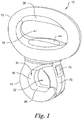
- a first preferred embodiment of the rotatable handle generally designated 10, and hereinafter referred to as the "rotatable handle" 10 in accordance with the present invention.
- the rotatable handle 10 is attachable to an object and graspable by a user's hand.
- the object is a tubular object having a generally circular cross section and a longitudinal extent.
- the rotatable handle 10 has an auxiliary handle 12 coupled to a hook 14 removably attachable to the object (not shown).
- the auxiliary handle 12 circumscribes a hand passageway 16 configured to receive a user's hand therein.
- a collar 18 is integrally formed as a portion of the auxiliary handle 12.
- the collar 18 has a collar bore 20 therethrough.
- the radially inwardly facing surface 22 of the collar bore 20 has a longitudinally extending keyway 24 therein.
- a compliant ergonomic grip 26 is preferably, but not necessarily, attached to an inner portion of the auxiliary handle 12 opposite the collar 18.
- the hook 14 has an upper end 28 and a lower end 30 and defines an object passageway 32 adjustably sized to receive the object.
- the inwardly facing (or concave) surface 34 of the hook 14 has an arcuate portion 36 and a straight portion 38.
- one or more compliant hook pads 40 are attached to the inwardly facing surface 34 of the hook 14.
- a shank 42 is integrally formed with and extends from the upper end 28 of the hook 14.
- the shank 42 has a longitudinal axis A 1 .
- a flange 44 is integrally formed with the free end 46 of the shank 42 and has a downwardly facing flange surface 48 extending radially outwardly from the shank 42.
- the flange surface 48 has a plurality of flange teeth 50 extending therefrom.
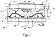
- a clutch 52 operatively couples the shank 44 to the collar portion 18 of the handle 12.
- the shank 42 is moveable only in translation along the longitudinal axis A 1 relative to the collar 18 when the clutch 52 is in an engaged position.
- the shank 42 is movable in rotation about the longitudinal axis A 1 relative to the collar 18 when the clutch 52 is in a disengaged position.
- the clutch 52 is biased in the engaged position.
- the clutch 52 comprises a clutch ring 54 disposed in the collar 18.
- the clutch ring 54 is formed as two semi-cylindrical pieces that snap together.
- the clutch ring 54 may be a one-piece molded construction.
- the clutch ring 54 has a clutch-ring bore 56 within which a portion of the shank 42 is disposed.
- the clutch ring 54 has a key 58 extending radially outwardly into the keyway 24 of the collar 18 preventing rotation of the clutch ring 54 relative to the collar 18.
- the clutch ring 54 has an annular clutch-ring surface 60 opposing and frictionally engaging the flange surface 48 when the clutch 52 is in the engaged position.
- the clutch-ring surface 60 preferably, but not necessarily, has a plurality of clutch-ring teeth 62 extending therefrom and engaged with the plurality of flange teeth 62 when the clutch 52 is in the engaged position.
- a wave washer 64 biases the clutch 52 in the engaged position.
- a ratchet 66 is integrally formed on the arcuate, inwardly facing surface portion 34 of the upper end 28 of the hook 14.
- the ratchet 66 has a plurality of ratchet teeth 68.
- a pivot arm 70 is attached to the lower end 30 of the hook 14.
- the pivot arm 70 extends toward the ratchet 66 and is rotatable about a transverse axis A 2 perpendicular to the longitudinal axis A 1 of the shank 14 from a first position P 1 allowing access to the object passageway 32 to one of a plurality of second positions P 2 adjusting the size of the object passageway 32 to secure the object therein.
- one or more compliant pivot arm pads 72 are attached to the inner surface 74 of the pivot arm 70.
- a pawl 76 is attached to the pivot arm 70 for rotation therewith.
- the pawl 76 is slideable in translation relative to the pivot arm 70 between a first pawl position P 3 in which a free end 78 of the pawl 76 engages the ratchet 66 preventing rotation of the pivot arm 70 and a second pawl position P 4 in which the free end 78 of the pawl 76 is disengaged from the ratchet 66.
- the pawl 76 is biased in the first pawl position P3, by a biasing member 82 which preferably is a coil spring.
- At least one pawl tooth 80 on the free end 78 of the pawl 76 engages one ratchet tooth of the plurality of ratchet teeth 68 preventing rotation of the pivot arm 70 when the pawl 76 is in the first pawl position P 3 and the pivot arm 70 is in the second pivot arm position P 2 .
- the foregoing components (or piece parts) comprising the rotatable handle 10 may be fabricated by molding, casting, or machining. With the exception of the biasing elements which are preferably spring steel, the fabrication material of choice is a polymeric material, although, in some instances, a metal such as aluminum may be used.
- the auxiliary handle 12, hook 14, and pivot arm 72 are each preferably formed as two complementary pieces that are joined together by an adhesive, threaded fasteners or a snap fit manner well known in the art.
- the rotatable handle 10 is hereafter disclosed with respect to an object that is a carrier, such as a baby carrier or basket, having a carrier handle which is at least partially arcuate and/or in the shape of a generally inverted "U" and which has a generally circular cross-sectional shape.
- a carrier such as a baby carrier or basket
- a carrier handle which is at least partially arcuate and/or in the shape of a generally inverted "U" and which has a generally circular cross-sectional shape.
- Fig. 4 prior to use, the rotatable handle 10 is in the configuration shown therein.
- the pivot arm 70 is in the second pivot arm position P 2 forming with the radially inwardly facing (or concave) surface of the hook 14 the closed object passageway 32 and the pawl 76 is in the first pawl position P 3 engaging the ratchet 66.
- the user moves the pawl 76 in translation from the first pawl position P 3 to the second pawl position P 4 , disengaging the ratchet 66 and allowing the pivot arm 70 to move in rotation.
- the user rotates the pivot arm 70 from the second pivot arm position P 2 to the first pivot arm position P 1 , providing access to the object passageway 32.
- the pawl 76 may return to the first pawl position P 3 , under the force of the pawl biasing member 82.
- the carrier handle is placed in the object passageway 32.
- the pivot arm 70 is rotated to the second pivot arm position P 2 through an angular displacement sufficient to place the pivot arm pad 72 in compression against the carrier handle and to have the pawl 76 re-engage the ratchet 66 releasably retaining the carrier handle in the object passageway 32.
- the clutch 52 may be disengaged to allow rotation of the shank 42 relative to the handle 12 until the palm of the user's hand grasping the auxiliary handle 12 is in an ergonomically natural position.
- the clutch 52 may be disengaged allowing the desired rotation by pressing the auxiliary handle 12 downwardly toward the carrier handle, until the teeth 50 on the flange 44 of the shank 42 no longer engage the teeth 62 on the clutch ring 54.
- the hook 14 of the rotational handle 10 may be attached to the horizontal bar in a manner similar to the steps described above for use with a carrier such that the auxiliary handle 12 suspended downwardly from the bar.
- the auxiliary handle 12 may be rotated to an ergonomically comfortable position by disengaging the clutch 52 as discussed above.
Landscapes
- Engineering & Computer Science (AREA)
- Mechanical Engineering (AREA)
- General Engineering & Computer Science (AREA)
- Physics & Mathematics (AREA)
- Automation & Control Theory (AREA)
- General Physics & Mathematics (AREA)
- Child & Adolescent Psychology (AREA)
- Transportation (AREA)
- Aviation & Aerospace Engineering (AREA)
- General Health & Medical Sciences (AREA)
- Health & Medical Sciences (AREA)
- Mechanical Control Devices (AREA)
- Details Of Rigid Or Semi-Rigid Containers (AREA)
- Seats For Vehicles (AREA)
- Pivots And Pivotal Connections (AREA)
- Steering Devices For Bicycles And Motorcycles (AREA)
- Walking Sticks, Umbrellas, And Fans (AREA)
- Purses, Travelling Bags, Baskets, Or Suitcases (AREA)
Applications Claiming Priority (1)
| Application Number | Priority Date | Filing Date | Title |
|---|---|---|---|
| US14/878,154 US9507371B1 (en) | 2015-10-08 | 2015-10-08 | Rotatable handle attachable to an object having a longitudinal extent |
Publications (3)
| Publication Number | Publication Date |
|---|---|
| EP3156190A2 EP3156190A2 (en) | 2017-04-19 |
| EP3156190A3 EP3156190A3 (en) | 2017-05-10 |
| EP3156190B1 true EP3156190B1 (en) | 2018-09-12 |
Family
ID=57121083
Family Applications (1)
| Application Number | Title | Priority Date | Filing Date |
|---|---|---|---|
| EP16192524.3A Not-in-force EP3156190B1 (en) | 2015-10-08 | 2016-10-06 | Rotatable handle attachable to an object having a longitudinal extent |
Country Status (6)
| Country | Link |
|---|---|
| US (3) | US9507371B1 (enExample) |
| EP (1) | EP3156190B1 (enExample) |
| JP (1) | JP6867135B2 (enExample) |
| CN (1) | CN107020605B (enExample) |
| AU (1) | AU2016238945A1 (enExample) |
| CA (1) | CA2944207A1 (enExample) |
Families Citing this family (14)
| Publication number | Priority date | Publication date | Assignee | Title |
|---|---|---|---|---|
| US10448771B1 (en) * | 2014-08-08 | 2019-10-22 | Qoi Products Llc | Bag clamp |
| US10448770B1 (en) * | 2014-08-08 | 2019-10-22 | Qoi Products Llc | Bag clamp |
| US10442073B2 (en) * | 2015-10-16 | 2019-10-15 | Kenneth J. Brauer | Rotating handle and related methods |
| US10252903B2 (en) * | 2016-06-29 | 2019-04-09 | Radical Resolutions LLC | Hose puller and method |
| US10247212B2 (en) * | 2017-07-27 | 2019-04-02 | Lawrence E. Nunes | Device for mounting an object |
| CN107744243A (zh) * | 2017-11-04 | 2018-03-02 | 辽宁石油化工大学 | 一种购物袋手拎器 |
| US11607795B2 (en) * | 2019-12-13 | 2023-03-21 | Kenneth J. Brauer | Rotating handle and related methods |
| US11766035B2 (en) * | 2020-03-19 | 2023-09-26 | Joseph Alfaro | Fishing rod handling device |
| CN111453330B (zh) * | 2020-04-28 | 2021-10-19 | 福州联泓交通器材有限公司 | 一种汽车工件智能悬挂、输送及控制方法 |
| CN113057416A (zh) * | 2021-04-08 | 2021-07-02 | 东莞市乐业五金有限公司 | 钩子 |
| KR102448381B1 (ko) * | 2022-04-26 | 2022-09-27 | 윤순용 | 각도조절이 가능한 다용도 운동용 손잡이 |
| US12349624B2 (en) * | 2022-10-19 | 2025-07-08 | Echo Incorporated | Portable tool with adjustable gripping assembly |
| USD1013074S1 (en) * | 2023-07-13 | 2024-01-30 | Eliott Ekindi | Universal exercise clip |
| US12240095B1 (en) * | 2024-09-16 | 2025-03-04 | Hank Hung Kung Chou | Apparatus for an ergonomic rotatable gardening tool handle |
Family Cites Families (62)
| Publication number | Priority date | Publication date | Assignee | Title |
|---|---|---|---|---|
| US2266850A (en) * | 1940-12-21 | 1941-12-23 | Mcbee Co | Adjustable base for ledger trays |
| JPS51122970U (enExample) * | 1975-03-31 | 1976-10-05 | ||
| US4059209A (en) | 1976-07-01 | 1977-11-22 | Grizzley Ski Lock Corporation | Carrier and lock for ski equipment |
| US4112541A (en) * | 1977-05-31 | 1978-09-12 | Constantinos Tetradis | Handle for bags particularly of net or plastic material |
| US4466523A (en) | 1982-06-29 | 1984-08-21 | The Stanley Works | Ratchet mechanism |
| GB2123280B (en) * | 1982-07-02 | 1986-01-22 | Harold Eley | Carrying handle |
| US4523781A (en) | 1984-02-23 | 1985-06-18 | Hal Brody | Gripping aid for the manually disabled |
| US5207476A (en) | 1989-10-24 | 1993-05-04 | North States Industries, Inc. | Infant seat with longitudinally-oriented handle |
| US5544935A (en) | 1994-10-20 | 1996-08-13 | Cosco, Inc. | Carrier apparatus |
| JPH08243953A (ja) * | 1995-03-07 | 1996-09-24 | Makita Corp | 電動工具のサイドハンドル |
| US5632657A (en) * | 1995-04-02 | 1997-05-27 | Brunswick Corporation | Multi-position adjustable trolling motor tiller handle |
| USD374622S (en) | 1995-08-21 | 1996-10-15 | Winborne David E | Shopping bag handle grip |
| US5651581A (en) | 1995-09-22 | 1997-07-29 | Kolcraft Enterprises, Inc. | Infant seat handle |
| US5870800A (en) | 1996-05-23 | 1999-02-16 | Chao; Hua-Jen | Steering wheel rotating aid |
| US5725422A (en) * | 1996-10-17 | 1998-03-10 | Leweck; Joseph F. | Auto body buffing machine with handle angularly adjustable to different fixed positions |
| US5806924A (en) | 1996-12-17 | 1998-09-15 | Cambridge Industries, Inc. | Baby seat |
| GB2333242B (en) | 1998-01-16 | 1999-12-01 | Kuo Chun Mei | Modular toy toddler car seat |
| US6317924B1 (en) * | 1998-10-28 | 2001-11-20 | Mark Gallagher | Selectively rotatable handle for wheeled luggage |
| US6098500A (en) | 1998-12-11 | 2000-08-08 | Joda Enterprises, Inc. | Hand tool with ratchet handle and associated quick release mechanism |
| AU2757700A (en) * | 1999-02-08 | 2000-08-25 | Mark H. Ginocchio | Self-aligning handling or storing device and methods of use therefor |
| US6382549B1 (en) * | 2000-07-21 | 2002-05-07 | Christopher P. Krake | Holder for strings of decorative lights |
| USD451312S1 (en) | 2000-09-22 | 2001-12-04 | Cosco Management, Inc. | Carrying handle |
| US6688259B2 (en) | 2001-05-31 | 2004-02-10 | Wendy Axel | Handle with grip for comfortably holding articles by hand |
| US6581246B1 (en) * | 2001-10-02 | 2003-06-24 | Robert Reid Polette | Adjustable grass trimmer handle |
| US6629801B2 (en) * | 2001-10-18 | 2003-10-07 | Pao-Hsien Cheng | Position adjusting device for a stroller handle |
| US7097223B1 (en) * | 2003-04-24 | 2006-08-29 | Bradford Mark P | Shopping bag handle |
| US7014232B2 (en) | 2003-07-10 | 2006-03-21 | Alain Bosa | Removable auxiliary handle for tools |
| US6892866B2 (en) * | 2003-07-21 | 2005-05-17 | Hui-Ling Lai | Case with randomly adjusting handle |
| US20050085352A1 (en) | 2003-08-01 | 2005-04-21 | Baxter Brent A. | 360 degree rotator attachment for exercise equipment |
| JP2006015035A (ja) * | 2004-07-05 | 2006-01-19 | Teiirekkusu:Kk | ハンドル |
| DE102004036420A1 (de) * | 2004-07-27 | 2006-03-23 | Hilti Ag | Werkzeuggerätehandgriff |
| US20060026794A1 (en) | 2004-08-06 | 2006-02-09 | Streetman Kenneth E | Handle apparatus |
| US20060087139A1 (en) | 2004-10-26 | 2006-04-27 | Valtann Ayres | Carrier with rotating handle lock for lifting and carrying filled flexible bags |
| US20070060405A1 (en) | 2005-09-15 | 2007-03-15 | Matthew Grossman | Portable Infant Swing |
| US20070209162A1 (en) * | 2006-03-09 | 2007-09-13 | Mcroberts Jason | Auxiliary handle for reciprocating saw |
| ES2325842B1 (es) | 2006-03-10 | 2010-04-21 | Macsa Id, S.A. | "equipo para marcado por rayos laser". |
| US7203978B1 (en) * | 2006-05-26 | 2007-04-17 | Shih-Kuo Chang | Swivel handle structure for a bathtub |
| US7657972B2 (en) | 2006-08-21 | 2010-02-09 | Graeme Reid Jenkins | Handle attachment assembly |
| DE102006055014A1 (de) | 2006-11-22 | 2008-05-29 | Robert Bosch Gmbh | Zusatzhandgriff mit Exzenterspannhebel für eine Handwerkzeugmaschine |
| US7882596B2 (en) | 2007-02-15 | 2011-02-08 | Motion Minder Llc | Adjustable handle clamp systems and methods |
| US20080217368A1 (en) | 2007-03-08 | 2008-09-11 | Melvin John Denton | Hands-free load carrying apparatus |
| JP5000353B2 (ja) * | 2007-03-29 | 2012-08-15 | 株式会社マキタ | 手持ち工具のハンドル |
| US8453296B2 (en) | 2008-04-01 | 2013-06-04 | David Swerdlick | Ergonomic handle system for work tool |
| US20090289153A1 (en) | 2008-05-21 | 2009-11-26 | Gaffney Jarrell | Device for Carrying Bags |
| DE102008042111A1 (de) | 2008-09-15 | 2010-03-18 | Hilti Aktiengesellschaft | Zusatzhandgriff für eine Handwerkzeugmaschine |
| DE102008042114A1 (de) * | 2008-09-15 | 2010-03-18 | Hilti Aktiengesellschaft | Zusatzhandgriff für eine Handwerkzeugmaschine |
| US7730588B1 (en) | 2008-11-13 | 2010-06-08 | Claude Bernier | Fire hose holding apparatus |
| US8894456B2 (en) | 2008-11-20 | 2014-11-25 | Lawrence Scott Bucknell | Compound rotating handle |
| USD619367S1 (en) | 2008-11-20 | 2010-07-13 | Beifa Group Co., Ltd. | Handheld device for carrying bags |
| JP5297890B2 (ja) | 2008-12-03 | 2013-09-25 | 本田技研工業株式会社 | パイプハンドル保持機構 |
| CN201323993Y (zh) | 2008-12-16 | 2009-10-14 | 贝发集团股份有限公司 | 一种提物把手 |
| US7566292B1 (en) | 2009-04-17 | 2009-07-28 | Perfect Pushup, Llc | Handle assembly for use with an exercise bar |
| US20110173778A1 (en) | 2009-10-23 | 2011-07-21 | Michael Wales | Ergonomic auxiliary handle |
| US8104145B1 (en) * | 2010-01-02 | 2012-01-31 | Zoya, Inc. | Leash handle with storage drawer and swivel connection |
| US20120319342A1 (en) | 2010-02-23 | 2012-12-20 | Christopher Charles Macey | Pipe Clamp |
| US8381358B1 (en) | 2010-11-12 | 2013-02-26 | Mark Frey | Universal handle |
| DE102010063912A1 (de) * | 2010-12-22 | 2012-06-28 | Hilti Aktiengesellschaft | Zusatzgriff, Handwerkzeugmaschine, System |
| US8684454B2 (en) | 2011-04-20 | 2014-04-01 | Robert Chipman | Infant car seat |
| US8579345B2 (en) | 2011-05-16 | 2013-11-12 | IQPod, LLC | Ladder handle and transporting device |
| US8671523B1 (en) | 2013-03-14 | 2014-03-18 | Nathaniel R. Day | Carrier removably attachable to an object for more easily and ergonomically carrying the object |
| CN203456318U (zh) * | 2013-07-04 | 2014-02-26 | 施耐德电器工业公司 | 旋转手柄 |
| US9266477B2 (en) * | 2014-04-09 | 2016-02-23 | Ford Global Technologies, Llc | Stand alone push in coat hook |
-
2015
- 2015-10-08 US US14/878,154 patent/US9507371B1/en not_active Expired - Fee Related
-
2016
- 2016-09-30 CN CN201610875910.3A patent/CN107020605B/zh not_active Expired - Fee Related
- 2016-10-04 CA CA2944207A patent/CA2944207A1/en not_active Abandoned
- 2016-10-06 JP JP2016197959A patent/JP6867135B2/ja not_active Expired - Fee Related
- 2016-10-06 EP EP16192524.3A patent/EP3156190B1/en not_active Not-in-force
- 2016-10-07 AU AU2016238945A patent/AU2016238945A1/en not_active Abandoned
- 2016-11-18 US US15/355,414 patent/US9781993B2/en not_active Expired - Fee Related
-
2017
- 2017-10-09 US US15/727,740 patent/US9993064B2/en not_active Expired - Fee Related
Non-Patent Citations (1)
| Title |
|---|
| None * |
Also Published As
| Publication number | Publication date |
|---|---|
| CA2944207A1 (en) | 2017-04-08 |
| US20180125215A1 (en) | 2018-05-10 |
| CN107020605B (zh) | 2020-09-25 |
| US9781993B2 (en) | 2017-10-10 |
| CN107020605A (zh) | 2017-08-08 |
| JP6867135B2 (ja) | 2021-04-28 |
| US9993064B2 (en) | 2018-06-12 |
| US9507371B1 (en) | 2016-11-29 |
| EP3156190A2 (en) | 2017-04-19 |
| JP2017137194A (ja) | 2017-08-10 |
| AU2016238945A1 (en) | 2017-04-27 |
| EP3156190A3 (en) | 2017-05-10 |
| US20170099936A1 (en) | 2017-04-13 |
Similar Documents
| Publication | Publication Date | Title |
|---|---|---|
| EP3156190B1 (en) | Rotatable handle attachable to an object having a longitudinal extent | |
| US7231718B2 (en) | Multi-position locking tool | |
| US5658044A (en) | Infant carrier handle | |
| US9718181B2 (en) | Apparatus for ergonomic application of rotational handle garden tool | |
| US7698970B1 (en) | Carabiner multi-tool | |
| US8671523B1 (en) | Carrier removably attachable to an object for more easily and ergonomically carrying the object | |
| US8550484B1 (en) | Adjustable bicycle handle bar adapter and associated method | |
| US10532241B2 (en) | Kettle bell and methods of use thereof | |
| US9717174B2 (en) | Ergonomic rotational handle for a garden tool | |
| US20160176039A1 (en) | Pistol grip attachment for use with a paintbrush | |
| US8876210B2 (en) | Double articulating dental chair headrest apparatus | |
| US8875355B2 (en) | Buckle | |
| HK1235744B (en) | Rotatable handle attachable to an object having a longitudinal extent | |
| HK1235744A1 (en) | Rotatable handle attachable to an object having a longitudinal extent | |
| US6513846B2 (en) | Length-adjustable ground-working tool | |
| US20170022039A1 (en) | Pry Bar | |
| WO2004103781A1 (en) | A seat belt presenter | |
| KR101910869B1 (ko) | 가방 끈 길이 조절장치 | |
| KR20160051941A (ko) | 웨어러블 크러치 | |
| US20230145445A1 (en) | Kettle bell and methods of use thereof | |
| GB2298158A (en) | Garden hand tool | |
| EP3278641A1 (en) | Apparatus for ergonomic application of rotational handle garden tool | |
| EP3759044A1 (en) | A saddle system | |
| CA3112737C (en) | Animal leash with longitudinally adjustable grip handle | |
| US20250000244A1 (en) | Carrying Strap Device |
Legal Events
| Date | Code | Title | Description |
|---|---|---|---|
| PUAI | Public reference made under article 153(3) epc to a published international application that has entered the european phase |
Free format text: ORIGINAL CODE: 0009012 |
|
| PUAL | Search report despatched |
Free format text: ORIGINAL CODE: 0009013 |
|
| AK | Designated contracting states |
Kind code of ref document: A2 Designated state(s): AL AT BE BG CH CY CZ DE DK EE ES FI FR GB GR HR HU IE IS IT LI LT LU LV MC MK MT NL NO PL PT RO RS SE SI SK SM TR |
|
| AX | Request for extension of the european patent |
Extension state: BA ME |
|
| AK | Designated contracting states |
Kind code of ref document: A3 Designated state(s): AL AT BE BG CH CY CZ DE DK EE ES FI FR GB GR HR HU IE IS IT LI LT LU LV MC MK MT NL NO PL PT RO RS SE SI SK SM TR |
|
| AX | Request for extension of the european patent |
Extension state: BA ME |
|
| RIC1 | Information provided on ipc code assigned before grant |
Ipc: B25G 1/06 20060101ALI20170404BHEP Ipc: B25F 5/02 20060101AFI20170404BHEP |
|
| 17P | Request for examination filed |
Effective date: 20170915 |
|
| RBV | Designated contracting states (corrected) |
Designated state(s): AL AT BE BG CH CY CZ DE DK EE ES FI FR GB GR HR HU IE IS IT LI LT LU LV MC MK MT NL NO PL PT RO RS SE SI SK SM TR |
|
| REG | Reference to a national code |
Ref country code: HK Ref legal event code: DE Ref document number: 1235744 Country of ref document: HK |
|
| GRAP | Despatch of communication of intention to grant a patent |
Free format text: ORIGINAL CODE: EPIDOSNIGR1 |
|
| RIC1 | Information provided on ipc code assigned before grant |
Ipc: B25G 1/06 20060101ALI20180322BHEP Ipc: B25F 5/02 20060101AFI20180322BHEP |
|
| INTG | Intention to grant announced |
Effective date: 20180409 |
|
| GRAS | Grant fee paid |
Free format text: ORIGINAL CODE: EPIDOSNIGR3 |
|
| GRAA | (expected) grant |
Free format text: ORIGINAL CODE: 0009210 |
|
| AK | Designated contracting states |
Kind code of ref document: B1 Designated state(s): AL AT BE BG CH CY CZ DE DK EE ES FI FR GB GR HR HU IE IS IT LI LT LU LV MC MK MT NL NO PL PT RO RS SE SI SK SM TR |
|
| REG | Reference to a national code |
Ref country code: GB Ref legal event code: FG4D |
|
| REG | Reference to a national code |
Ref country code: CH Ref legal event code: EP |
|
| REG | Reference to a national code |
Ref country code: IE Ref legal event code: FG4D |
|
| REG | Reference to a national code |
Ref country code: DE Ref legal event code: R096 Ref document number: 602016005527 Country of ref document: DE |
|
| REG | Reference to a national code |
Ref country code: AT Ref legal event code: REF Ref document number: 1039996 Country of ref document: AT Kind code of ref document: T Effective date: 20181015 |
|
| REG | Reference to a national code |
Ref country code: FR Ref legal event code: PLFP Year of fee payment: 3 |
|
| REG | Reference to a national code |
Ref country code: NL Ref legal event code: MP Effective date: 20180912 |
|
| REG | Reference to a national code |
Ref country code: LT Ref legal event code: MG4D |
|
| PG25 | Lapsed in a contracting state [announced via postgrant information from national office to epo] |
Ref country code: GR Free format text: LAPSE BECAUSE OF FAILURE TO SUBMIT A TRANSLATION OF THE DESCRIPTION OR TO PAY THE FEE WITHIN THE PRESCRIBED TIME-LIMIT Effective date: 20181213 Ref country code: NO Free format text: LAPSE BECAUSE OF FAILURE TO SUBMIT A TRANSLATION OF THE DESCRIPTION OR TO PAY THE FEE WITHIN THE PRESCRIBED TIME-LIMIT Effective date: 20181212 Ref country code: SE Free format text: LAPSE BECAUSE OF FAILURE TO SUBMIT A TRANSLATION OF THE DESCRIPTION OR TO PAY THE FEE WITHIN THE PRESCRIBED TIME-LIMIT Effective date: 20180912 Ref country code: LT Free format text: LAPSE BECAUSE OF FAILURE TO SUBMIT A TRANSLATION OF THE DESCRIPTION OR TO PAY THE FEE WITHIN THE PRESCRIBED TIME-LIMIT Effective date: 20180912 Ref country code: FI Free format text: LAPSE BECAUSE OF FAILURE TO SUBMIT A TRANSLATION OF THE DESCRIPTION OR TO PAY THE FEE WITHIN THE PRESCRIBED TIME-LIMIT Effective date: 20180912 Ref country code: RS Free format text: LAPSE BECAUSE OF FAILURE TO SUBMIT A TRANSLATION OF THE DESCRIPTION OR TO PAY THE FEE WITHIN THE PRESCRIBED TIME-LIMIT Effective date: 20180912 Ref country code: BG Free format text: LAPSE BECAUSE OF FAILURE TO SUBMIT A TRANSLATION OF THE DESCRIPTION OR TO PAY THE FEE WITHIN THE PRESCRIBED TIME-LIMIT Effective date: 20181212 |
|
| PG25 | Lapsed in a contracting state [announced via postgrant information from national office to epo] |
Ref country code: AL Free format text: LAPSE BECAUSE OF FAILURE TO SUBMIT A TRANSLATION OF THE DESCRIPTION OR TO PAY THE FEE WITHIN THE PRESCRIBED TIME-LIMIT Effective date: 20180912 Ref country code: LV Free format text: LAPSE BECAUSE OF FAILURE TO SUBMIT A TRANSLATION OF THE DESCRIPTION OR TO PAY THE FEE WITHIN THE PRESCRIBED TIME-LIMIT Effective date: 20180912 Ref country code: HR Free format text: LAPSE BECAUSE OF FAILURE TO SUBMIT A TRANSLATION OF THE DESCRIPTION OR TO PAY THE FEE WITHIN THE PRESCRIBED TIME-LIMIT Effective date: 20180912 |
|
| REG | Reference to a national code |
Ref country code: AT Ref legal event code: MK05 Ref document number: 1039996 Country of ref document: AT Kind code of ref document: T Effective date: 20180912 |
|
| PG25 | Lapsed in a contracting state [announced via postgrant information from national office to epo] |
Ref country code: IS Free format text: LAPSE BECAUSE OF FAILURE TO SUBMIT A TRANSLATION OF THE DESCRIPTION OR TO PAY THE FEE WITHIN THE PRESCRIBED TIME-LIMIT Effective date: 20190112 Ref country code: AT Free format text: LAPSE BECAUSE OF FAILURE TO SUBMIT A TRANSLATION OF THE DESCRIPTION OR TO PAY THE FEE WITHIN THE PRESCRIBED TIME-LIMIT Effective date: 20180912 Ref country code: EE Free format text: LAPSE BECAUSE OF FAILURE TO SUBMIT A TRANSLATION OF THE DESCRIPTION OR TO PAY THE FEE WITHIN THE PRESCRIBED TIME-LIMIT Effective date: 20180912 Ref country code: PL Free format text: LAPSE BECAUSE OF FAILURE TO SUBMIT A TRANSLATION OF THE DESCRIPTION OR TO PAY THE FEE WITHIN THE PRESCRIBED TIME-LIMIT Effective date: 20180912 Ref country code: RO Free format text: LAPSE BECAUSE OF FAILURE TO SUBMIT A TRANSLATION OF THE DESCRIPTION OR TO PAY THE FEE WITHIN THE PRESCRIBED TIME-LIMIT Effective date: 20180912 Ref country code: NL Free format text: LAPSE BECAUSE OF FAILURE TO SUBMIT A TRANSLATION OF THE DESCRIPTION OR TO PAY THE FEE WITHIN THE PRESCRIBED TIME-LIMIT Effective date: 20180912 Ref country code: CZ Free format text: LAPSE BECAUSE OF FAILURE TO SUBMIT A TRANSLATION OF THE DESCRIPTION OR TO PAY THE FEE WITHIN THE PRESCRIBED TIME-LIMIT Effective date: 20180912 Ref country code: IT Free format text: LAPSE BECAUSE OF FAILURE TO SUBMIT A TRANSLATION OF THE DESCRIPTION OR TO PAY THE FEE WITHIN THE PRESCRIBED TIME-LIMIT Effective date: 20180912 |
|
| PG25 | Lapsed in a contracting state [announced via postgrant information from national office to epo] |
Ref country code: SM Free format text: LAPSE BECAUSE OF FAILURE TO SUBMIT A TRANSLATION OF THE DESCRIPTION OR TO PAY THE FEE WITHIN THE PRESCRIBED TIME-LIMIT Effective date: 20180912 Ref country code: PT Free format text: LAPSE BECAUSE OF FAILURE TO SUBMIT A TRANSLATION OF THE DESCRIPTION OR TO PAY THE FEE WITHIN THE PRESCRIBED TIME-LIMIT Effective date: 20190112 Ref country code: SK Free format text: LAPSE BECAUSE OF FAILURE TO SUBMIT A TRANSLATION OF THE DESCRIPTION OR TO PAY THE FEE WITHIN THE PRESCRIBED TIME-LIMIT Effective date: 20180912 |
|
| REG | Reference to a national code |
Ref country code: DE Ref legal event code: R097 Ref document number: 602016005527 Country of ref document: DE |
|
| REG | Reference to a national code |
Ref country code: BE Ref legal event code: MM Effective date: 20181031 |
|
| PG25 | Lapsed in a contracting state [announced via postgrant information from national office to epo] |
Ref country code: LU Free format text: LAPSE BECAUSE OF NON-PAYMENT OF DUE FEES Effective date: 20181006 |
|
| PLBE | No opposition filed within time limit |
Free format text: ORIGINAL CODE: 0009261 |
|
| STAA | Information on the status of an ep patent application or granted ep patent |
Free format text: STATUS: NO OPPOSITION FILED WITHIN TIME LIMIT |
|
| REG | Reference to a national code |
Ref country code: IE Ref legal event code: MM4A |
|
| PG25 | Lapsed in a contracting state [announced via postgrant information from national office to epo] |
Ref country code: DK Free format text: LAPSE BECAUSE OF FAILURE TO SUBMIT A TRANSLATION OF THE DESCRIPTION OR TO PAY THE FEE WITHIN THE PRESCRIBED TIME-LIMIT Effective date: 20180912 Ref country code: MC Free format text: LAPSE BECAUSE OF FAILURE TO SUBMIT A TRANSLATION OF THE DESCRIPTION OR TO PAY THE FEE WITHIN THE PRESCRIBED TIME-LIMIT Effective date: 20180912 Ref country code: ES Free format text: LAPSE BECAUSE OF FAILURE TO SUBMIT A TRANSLATION OF THE DESCRIPTION OR TO PAY THE FEE WITHIN THE PRESCRIBED TIME-LIMIT Effective date: 20180912 |
|
| 26N | No opposition filed |
Effective date: 20190613 |
|
| PG25 | Lapsed in a contracting state [announced via postgrant information from national office to epo] |
Ref country code: SI Free format text: LAPSE BECAUSE OF FAILURE TO SUBMIT A TRANSLATION OF THE DESCRIPTION OR TO PAY THE FEE WITHIN THE PRESCRIBED TIME-LIMIT Effective date: 20180912 Ref country code: BE Free format text: LAPSE BECAUSE OF NON-PAYMENT OF DUE FEES Effective date: 20181031 |
|
| PG25 | Lapsed in a contracting state [announced via postgrant information from national office to epo] |
Ref country code: IE Free format text: LAPSE BECAUSE OF NON-PAYMENT OF DUE FEES Effective date: 20181006 |
|
| PG25 | Lapsed in a contracting state [announced via postgrant information from national office to epo] |
Ref country code: MT Free format text: LAPSE BECAUSE OF NON-PAYMENT OF DUE FEES Effective date: 20181006 |
|
| PG25 | Lapsed in a contracting state [announced via postgrant information from national office to epo] |
Ref country code: TR Free format text: LAPSE BECAUSE OF FAILURE TO SUBMIT A TRANSLATION OF THE DESCRIPTION OR TO PAY THE FEE WITHIN THE PRESCRIBED TIME-LIMIT Effective date: 20180912 |
|
| REG | Reference to a national code |
Ref country code: CH Ref legal event code: PL |
|
| PG25 | Lapsed in a contracting state [announced via postgrant information from national office to epo] |
Ref country code: CY Free format text: LAPSE BECAUSE OF FAILURE TO SUBMIT A TRANSLATION OF THE DESCRIPTION OR TO PAY THE FEE WITHIN THE PRESCRIBED TIME-LIMIT Effective date: 20180912 Ref country code: MK Free format text: LAPSE BECAUSE OF NON-PAYMENT OF DUE FEES Effective date: 20180912 Ref country code: HU Free format text: LAPSE BECAUSE OF FAILURE TO SUBMIT A TRANSLATION OF THE DESCRIPTION OR TO PAY THE FEE WITHIN THE PRESCRIBED TIME-LIMIT; INVALID AB INITIO Effective date: 20161006 |
|
| PG25 | Lapsed in a contracting state [announced via postgrant information from national office to epo] |
Ref country code: CH Free format text: LAPSE BECAUSE OF NON-PAYMENT OF DUE FEES Effective date: 20191031 Ref country code: LI Free format text: LAPSE BECAUSE OF NON-PAYMENT OF DUE FEES Effective date: 20191031 |
|
| PGFP | Annual fee paid to national office [announced via postgrant information from national office to epo] |
Ref country code: FR Payment date: 20201125 Year of fee payment: 5 Ref country code: GB Payment date: 20201127 Year of fee payment: 5 Ref country code: DE Payment date: 20201127 Year of fee payment: 5 |
|
| REG | Reference to a national code |
Ref country code: DE Ref legal event code: R119 Ref document number: 602016005527 Country of ref document: DE |
|
| GBPC | Gb: european patent ceased through non-payment of renewal fee |
Effective date: 20211006 |
|
| PG25 | Lapsed in a contracting state [announced via postgrant information from national office to epo] |
Ref country code: GB Free format text: LAPSE BECAUSE OF NON-PAYMENT OF DUE FEES Effective date: 20211006 Ref country code: DE Free format text: LAPSE BECAUSE OF NON-PAYMENT OF DUE FEES Effective date: 20220503 |
|
| PG25 | Lapsed in a contracting state [announced via postgrant information from national office to epo] |
Ref country code: FR Free format text: LAPSE BECAUSE OF NON-PAYMENT OF DUE FEES Effective date: 20211031 |