EP3155481B1 - Appareil lithographique et procédé de fabrication d'appareil lithographique - Google Patents
Appareil lithographique et procédé de fabrication d'appareil lithographique Download PDFInfo
- Publication number
- EP3155481B1 EP3155481B1 EP15721224.2A EP15721224A EP3155481B1 EP 3155481 B1 EP3155481 B1 EP 3155481B1 EP 15721224 A EP15721224 A EP 15721224A EP 3155481 B1 EP3155481 B1 EP 3155481B1
- Authority
- EP
- European Patent Office
- Prior art keywords
- channel
- substrate
- lithographic apparatus
- liquid
- thermal load
- Prior art date
- Legal status (The legal status is an assumption and is not a legal conclusion. Google has not performed a legal analysis and makes no representation as to the accuracy of the status listed.)
- Active
Links
Images


Classifications
-
- G—PHYSICS
- G03—PHOTOGRAPHY; CINEMATOGRAPHY; ANALOGOUS TECHNIQUES USING WAVES OTHER THAN OPTICAL WAVES; ELECTROGRAPHY; HOLOGRAPHY
- G03F—PHOTOMECHANICAL PRODUCTION OF TEXTURED OR PATTERNED SURFACES, e.g. FOR PRINTING, FOR PROCESSING OF SEMICONDUCTOR DEVICES; MATERIALS THEREFOR; ORIGINALS THEREFOR; APPARATUS SPECIALLY ADAPTED THEREFOR
- G03F7/00—Photomechanical, e.g. photolithographic, production of textured or patterned surfaces, e.g. printing surfaces; Materials therefor, e.g. comprising photoresists; Apparatus specially adapted therefor
- G03F7/70—Microphotolithographic exposure; Apparatus therefor
- G03F7/70216—Mask projection systems
- G03F7/70341—Details of immersion lithography aspects, e.g. exposure media or control of immersion liquid supply
-
- G—PHYSICS
- G03—PHOTOGRAPHY; CINEMATOGRAPHY; ANALOGOUS TECHNIQUES USING WAVES OTHER THAN OPTICAL WAVES; ELECTROGRAPHY; HOLOGRAPHY
- G03F—PHOTOMECHANICAL PRODUCTION OF TEXTURED OR PATTERNED SURFACES, e.g. FOR PRINTING, FOR PROCESSING OF SEMICONDUCTOR DEVICES; MATERIALS THEREFOR; ORIGINALS THEREFOR; APPARATUS SPECIALLY ADAPTED THEREFOR
- G03F7/00—Photomechanical, e.g. photolithographic, production of textured or patterned surfaces, e.g. printing surfaces; Materials therefor, e.g. comprising photoresists; Apparatus specially adapted therefor
- G03F7/70—Microphotolithographic exposure; Apparatus therefor
- G03F7/70691—Handling of masks or workpieces
- G03F7/70733—Handling masks and workpieces, e.g. exchange of workpiece or mask, transport of workpiece or mask
-
- G—PHYSICS
- G03—PHOTOGRAPHY; CINEMATOGRAPHY; ANALOGOUS TECHNIQUES USING WAVES OTHER THAN OPTICAL WAVES; ELECTROGRAPHY; HOLOGRAPHY
- G03F—PHOTOMECHANICAL PRODUCTION OF TEXTURED OR PATTERNED SURFACES, e.g. FOR PRINTING, FOR PROCESSING OF SEMICONDUCTOR DEVICES; MATERIALS THEREFOR; ORIGINALS THEREFOR; APPARATUS SPECIALLY ADAPTED THEREFOR
- G03F7/00—Photomechanical, e.g. photolithographic, production of textured or patterned surfaces, e.g. printing surfaces; Materials therefor, e.g. comprising photoresists; Apparatus specially adapted therefor
- G03F7/70—Microphotolithographic exposure; Apparatus therefor
- G03F7/708—Construction of apparatus, e.g. environment aspects, hygiene aspects or materials
- G03F7/70858—Environment aspects, e.g. pressure of beam-path gas, temperature
- G03F7/70866—Environment aspects, e.g. pressure of beam-path gas, temperature of mask or workpiece
- G03F7/70875—Temperature, e.g. temperature control of masks or workpieces via control of stage temperature
-
- G—PHYSICS
- G03—PHOTOGRAPHY; CINEMATOGRAPHY; ANALOGOUS TECHNIQUES USING WAVES OTHER THAN OPTICAL WAVES; ELECTROGRAPHY; HOLOGRAPHY
- G03F—PHOTOMECHANICAL PRODUCTION OF TEXTURED OR PATTERNED SURFACES, e.g. FOR PRINTING, FOR PROCESSING OF SEMICONDUCTOR DEVICES; MATERIALS THEREFOR; ORIGINALS THEREFOR; APPARATUS SPECIALLY ADAPTED THEREFOR
- G03F7/00—Photomechanical, e.g. photolithographic, production of textured or patterned surfaces, e.g. printing surfaces; Materials therefor, e.g. comprising photoresists; Apparatus specially adapted therefor
- G03F7/70—Microphotolithographic exposure; Apparatus therefor
- G03F7/708—Construction of apparatus, e.g. environment aspects, hygiene aspects or materials
- G03F7/70858—Environment aspects, e.g. pressure of beam-path gas, temperature
- G03F7/70883—Environment aspects, e.g. pressure of beam-path gas, temperature of optical system
- G03F7/70891—Temperature
-
- G—PHYSICS
- G03—PHOTOGRAPHY; CINEMATOGRAPHY; ANALOGOUS TECHNIQUES USING WAVES OTHER THAN OPTICAL WAVES; ELECTROGRAPHY; HOLOGRAPHY
- G03F—PHOTOMECHANICAL PRODUCTION OF TEXTURED OR PATTERNED SURFACES, e.g. FOR PRINTING, FOR PROCESSING OF SEMICONDUCTOR DEVICES; MATERIALS THEREFOR; ORIGINALS THEREFOR; APPARATUS SPECIALLY ADAPTED THEREFOR
- G03F7/00—Photomechanical, e.g. photolithographic, production of textured or patterned surfaces, e.g. printing surfaces; Materials therefor, e.g. comprising photoresists; Apparatus specially adapted therefor
- G03F7/70—Microphotolithographic exposure; Apparatus therefor
- G03F7/708—Construction of apparatus, e.g. environment aspects, hygiene aspects or materials
- G03F7/7095—Materials, e.g. materials for housing, stage or other support having particular properties, e.g. weight, strength, conductivity, thermal expansion coefficient
-
- H—ELECTRICITY
- H01—ELECTRIC ELEMENTS
- H01L—SEMICONDUCTOR DEVICES NOT COVERED BY CLASS H10
- H01L21/00—Processes or apparatus adapted for the manufacture or treatment of semiconductor or solid state devices or of parts thereof
- H01L21/02—Manufacture or treatment of semiconductor devices or of parts thereof
- H01L21/027—Making masks on semiconductor bodies for further photolithographic processing not provided for in group H01L21/18 or H01L21/34
- H01L21/0271—Making masks on semiconductor bodies for further photolithographic processing not provided for in group H01L21/18 or H01L21/34 comprising organic layers
- H01L21/0273—Making masks on semiconductor bodies for further photolithographic processing not provided for in group H01L21/18 or H01L21/34 comprising organic layers characterised by the treatment of photoresist layers
- H01L21/0274—Photolithographic processes
Definitions
- the present invention relates to an immersion lithographic apparatus and a method of manufacturing an immersion lithographic apparatus.
- a lithographic apparatus is a machine that applies a desired pattern onto a substrate, usually onto a target portion of the substrate.
- a lithographic apparatus can be used, for example, in the manufacture of integrated circuits (ICs).
- a patterning device which is alternatively referred to as a mask or a reticle, may be used to generate a circuit pattern to be formed on an individual layer of the IC.
- This pattern can be transferred onto a target portion (e.g. including part of, one, or several dies) on a substrate (e.g. a silicon wafer). Transfer of the pattern is typically via imaging onto a layer of radiation-sensitive material (resist) provided on the substrate.
- resist radiation-sensitive material
- a single substrate will contain a network of adjacent target portions that are successively patterned.
- Conventional lithographic apparatus include so-called steppers, in which each target portion is irradiated by exposing an entire pattern onto the target portion at once, and so-called scanners, in which each target portion is irradiated by scanning the pattern through a radiation beam in a given direction (the "scanning"-direction) while synchronously scanning the substrate parallel or anti parallel to this direction. It is also possible to transfer the pattern from the patterning device to the substrate by imprinting the pattern onto the substrate.
- immersion fluid is handled by a fluid handling system, device structure or apparatus.
- the fluid handling system may supply immersion fluid and therefore be a fluid supply system.
- the fluid handling system may at least partly confine immersion fluid and thereby be a fluid confinement system.
- the fluid handling system may provide a barrier to immersion fluid and thereby be a barrier member, such as a fluid confinement structure.
- the fluid handling system may create or use a flow of gas, for example to help in controlling the flow and/or the position of the immersion fluid. The flow of gas may form a seal to confine the immersion fluid so the fluid handling structure may be referred to as a seal member; such a seal member may be a fluid confinement structure.
- immersion liquid is used as the immersion fluid.
- the fluid handling system may be a liquid handling system.
- reference in this paragraph to a feature defined with respect to fluid may be understood to include a feature defined with respect to liquid.
- a gap normally exists between an object, such as a substrate and/or a sensor, and a table (e.g. a substrate table or a measurement table) around the edge of the object (e.g., substrate and/or sensor).
- a table e.g. a substrate table or a measurement table
- U.S. patent application publication US 2005-0264778 discloses filling that gap with material or providing a liquid source or low pressure source to deliberately fill the gap with liquid in order to avoid bubble inclusion as the gap passes under the liquid supply system and/or to remove any liquid which does enter the gap.
- Liquid from a gap between an edge of an object and a table on which the object is position may be removed through a channel.
- gas may also be removed through the channel.
- a two phase flow of liquid and gas may pass through the channel.
- Such a channel for two phase flow may be present in other parts of the lithographic apparatus, for example in a liquid confinement system. Such a two phase flow can lead to undesirable temperature changes in the component that the channel is formed in, or other nearby components.
- WO 2013/178438 A1 discloses a support body made of a second material, a channel formed in the support body, an element made of a first material and a coating applied to the first material.
- an immersion lithographic apparatus as appended in claim 1.
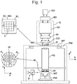
- FIG. 1 schematically depicts a lithographic apparatus according to one embodiment of the invention.
- the apparatus includes an illumination system (illuminator) IL configured to condition a radiation beam B (e.g. UV radiation or any other suitable radiation), a mask support structure (e.g. a mask table) MT constructed to support a patterning device (e.g. a mask) MA and connected to a first positioning device PM configured to accurately position the patterning device in accordance with certain parameters.
- the apparatus also includes a substrate table (e.g. a wafer table) WT or "substrate support" constructed to hold a substrate (e.g. a resist-coated wafer) W and connected to a second positioning device PW configured to accurately position the substrate in accordance with certain parameters.
- a radiation beam B e.g. UV radiation or any other suitable radiation
- a mask support structure e.g. a mask table
- MT constructed to support a patterning device (e.g. a mask) MA and connected to a
- the apparatus further includes a projection system (e.g. a refractive projection lens system) PS configured to project a pattern imparted to the radiation beam B by patterning device MA onto a target portion C (e.g. including one or more dies) of the substrate W.
- a projection system e.g. a refractive projection lens system
- PS configured to project a pattern imparted to the radiation beam B by patterning device MA onto a target portion C (e.g. including one or more dies) of the substrate W.
- the illumination system may include various types of optical components, such as refractive, reflective, magnetic, electromagnetic, electrostatic or other types of optical components, or any combination thereof, for directing, shaping, or controlling radiation.
- optical components such as refractive, reflective, magnetic, electromagnetic, electrostatic or other types of optical components, or any combination thereof, for directing, shaping, or controlling radiation.
- the mask support structure supports, i.e. bears the weight of, the patterning device. It holds the patterning device in a manner that depends on the orientation of the patterning device, the design of the lithographic apparatus, and other conditions, such as for example whether or not the patterning device is held in a vacuum environment.
- the mask support structure can use mechanical, vacuum, electrostatic or other clamping techniques to hold the patterning device.
- the mask support structure may be a frame or a table, for example, which may be fixed or movable as required.
- the mask support structure may ensure that the patterning device is at a desired position, for example with respect to the projection system. Any use of the terms "reticle” or “mask” herein may be considered synonymous with the more general term "patterning device.”
- patterning device used herein should be broadly interpreted as referring to any device that can be used to impart a radiation beam with a pattern in its cross-section so as to create a pattern in a target portion of the substrate. It should be noted that the pattern imparted to the radiation beam may not exactly correspond to the desired pattern in the target portion of the substrate, for example if the pattern includes phase-shifting features or so called assist features. Generally, the pattern imparted to the radiation beam will correspond to a particular functional layer in a device being created in the target portion, such as an integrated circuit.
- the patterning device may be transmissive or reflective.
- Examples of patterning devices include masks, programmable mirror arrays, and programmable LCD panels.
- Masks are well known in lithography, and include mask types such as binary, alternating phase-shift, and attenuated phase-shift, as well as various hybrid mask types.
- An example of a programmable mirror array employs a matrix arrangement of small mirrors, each of which can be individually tilted so as to reflect an incoming radiation beam in different directions. The tilted mirrors impart a pattern in a radiation beam which is reflected by the mirror matrix.
- projection system used herein should be broadly interpreted as encompassing any type of projection system, including refractive, reflective, catadioptric, magnetic, electromagnetic and electrostatic optical systems, or any combination thereof, as appropriate for the exposure radiation being used, or for other factors such as the use of an immersion liquid or the use of a vacuum. Any use of the term “projection lens” herein may be considered as synonymous with the more general term “projection system”.
- the apparatus is of a transmissive type (e.g. employing a transmissive mask).
- the apparatus may be of a reflective type (e.g. employing a programmable mirror array of a type as referred to above, or employing a reflective mask).
- the lithographic apparatus may be of a type having two (dual stage) or more substrate tables or “substrate supports” (and/or two or more mask tables or “mask supports”).
- substrate tables or “substrate supports” and/or two or more mask tables or “mask supports”
- additional tables or supports may be used in parallel, or preparatory steps may be carried out on one or more tables or supports while one or more other tables or supports are being used for exposure.
- the lithographic apparatus may also be of a type wherein at least a portion of the substrate may be covered by a liquid having a relatively high refractive index, e.g. water, so as to fill a space between the projection system and the substrate.
- a liquid having a relatively high refractive index e.g. water
- An immersion liquid may also be applied to other spaces in the lithographic apparatus, for example, between the mask and the projection system. Immersion techniques can be used to increase the numerical aperture of projection systems.
- immersion as used herein does not mean that a structure, such as a substrate, must be submerged in liquid, but rather only means that a liquid is located between the projection system and the substrate during exposure.
- the illuminator IL receives a radiation beam from a radiation source SO.
- the source and the lithographic apparatus may be separate entities, for example when the source is an excimer laser. In such cases, the source is not considered to form part of the lithographic apparatus and the radiation beam is passed from the source SO to the illuminator IL with the aid of a beam delivery system BD including, for example, suitable directing mirrors and/or a beam expander. In other cases the source may be an integral part of the lithographic apparatus, for example when the source is a mercury lamp.
- the source SO and the illuminator IL, together with the beam delivery system BD if required, may be referred to as a radiation system.
- the illuminator IL may include an adjuster AD configured to adjust the angular intensity distribution of the radiation beam. Generally, at least the outer and/or inner radial extent (commonly referred to as ⁇ -outer and ⁇ -inner, respectively) of the intensity distribution in a pupil plane of the illuminator can be adjusted.
- the illuminator IL may include various other components, such as an integrator IN and a condenser CO.
- the illuminator may be used to condition the radiation beam, to have a desired uniformity and intensity distribution in its cross-section. Similar to the source SO, the illuminator IL may or may not be considered to form part of the lithographic apparatus.
- the illuminator IL may be an integral part of the lithographic apparatus or may be a separate entity from the lithographic apparatus. In the latter case, the lithographic apparatus may be configured to allow the illuminator IL to be mounted thereon.
- the illuminator IL is detachable and may be separately provided (for example, by the lithographic apparatus manufacturer or another supplier).
- the radiation beam B is incident on the patterning device (e.g., mask MA), which is held on the mask support structure (e.g., mask table MT), and is patterned by the patterning device. Having traversed the mask MA, the radiation beam B passes through the projection system PS, which focuses the beam onto a target portion C of the substrate W.
- the substrate table WT can be moved accurately, e.g. so as to position different target portions C in the path of the radiation beam B.
- the first positioning device PM and another position sensor can be used to accurately position the mask MA with respect to the path of the radiation beam B, e.g. after mechanical retrieval from a mask library, or during a scan.
- movement of the mask table MT may be realized with the aid of a long-stroke module (coarse positioning) and a short-stroke module (fine positioning), which form part of the first positioning device PM.
- movement of the substrate table WT or "substrate support" may be realized using a long-stroke module and a short-stroke module, which form part of the second positioner PW.
- the mask table MT may be connected to a short-stroke actuator only, or may be fixed.
- Mask MA and substrate W may be aligned using mask alignment marks M1, M2 and substrate alignment marks PI, P2.
- the substrate alignment marks as illustrated occupy dedicated target portions, they may be located in spaces between target portions (these are known as scribe-lane alignment marks).
- the mask alignment marks may be located between the dies.
- Arrangements for providing liquid between a final element of the projection system PS and the substrate can be classed into three general categories. These are the bath type arrangement, the so-called localized immersion system and the all-wet immersion system. In a bath type arrangement substantially the whole of the substrate W and optionally part of the substrate table WT is submersed in a bath of liquid.
- An arrangement which has been proposed is to provide the liquid supply system with a liquid confinement structure which extends along at least a part of a boundary of the space between the final element of the projection system and the substrate, substrate table or both. Such an arrangement is illustrated in Figure 2 .
- the arrangement illustrated in Figure 2 and described below may be applied to the lithographic apparatus described above and illustrated in Figure 1 .
- Figure 2 schematically depicts a localized liquid supply system or fluid handling system with a liquid confinement structure IH, which extends along at least a part of a boundary of the space between the final element of the projection system and the substrate table WT or substrate W.
- a seal is formed between the liquid confinement structure IH and the surface of the substrate W and which may be a contactless seal such as a gas seal (such a system with a gas seal is disclosed in European patent application publication no. EP-A-1,420,298 ) or a liquid seal.
- the liquid confinement structure IH at least partly contains liquid in the space 11 between a final element of the projection system PS and the substrate W.
- the space 11 is at least partly formed by the liquid confinement structure IH positioned below and surrounding the final element of the projection system PS. Liquid is brought into the space below the projection system PS and within the liquid confinement structure IH by liquid inlet 13. The liquid may be removed by liquid outlet 13.
- the liquid may be contained in the space 11 by a gas seal 16 which, during use, is formed between the bottom of the liquid confinement structure IH and the surface of the substrate W.
- the gas in the gas seal is provided under pressure via inlet 15 to the gap between the liquid confinement structure IH and substrate W.
- the gas is extracted via a channel associated with outlet 14.
- the overpressure on the gas inlet 15, vacuum level on the outlet 14 and geometry of the gap are arranged so that there is a high-velocity gas flow 16 inwardly that confines the liquid.
- the force of the gas on the liquid between the liquid confinement structure IH and the substrate W contains the liquid in a space 11.
- Such a system is disclosed in United States patent application publication no. US 2004-0207824 .
- the liquid confinement structure IH does not have a gas seal.
- the substrate W is moved under the projection system PS and the liquid supply system.
- the substrate table is to be moved such that a dummy substrate or so-called closing plate can be positioned under the liquid supply system to enable, for example, substrate swap to take place, an edge of the substrate W (or other object) will pass under the space 11.
- Liquid may leak into the gap between the substrate W and substrate table WT. This liquid may be forced in under hydrostatic or hydrodynamic pressure or the force of a gas knife or other gas flow creating device.
- FIG 3 is a side cross sectional view that depicts a further liquid supply system or fluid handling system according to an embodiment.
- the arrangement illustrated in Figure 3 and described below may be applied to the lithographic apparatus described above and illustrated in Figure 1 .
- the liquid supply system is provided with a liquid confinement structure IH, which extends along at least a part of a boundary of the space between the final element of the projection system PS and the substrate table WT or substrate W.
- a liquid confinement structure IH which extends along at least a part of a boundary of the space between the final element of the projection system PS and the substrate table WT or substrate W.
- the liquid confinement structure IH at least partly contains liquid in the space 11 between a final element of the projection system PS and the substrate W.
- the space 11 is at least partly formed by the liquid confinement structure IH positioned below and surrounding the final element of the projection system PS.
- the liquid confinement structure IH comprises a main body member 53 and a porous member 83.
- the porous member 83 is plate shaped and has a plurality of holes (i.e., openings or pores).
- the porous member 83 is a mesh plate wherein numerous small holes 84 are formed in a mesh.
- the main body member 53 comprises supply ports 72, which are capable of supplying the liquid to the space 11, and a recovery port 73, which is capable of recovering the liquid from the space 11.
- the supply ports 72 are connected to a liquid supply apparatus 75 via passageways 74.
- the liquid supply apparatus 75 is capable of supplying the liquid to the supply ports 72.
- the liquid that is fed from the liquid supply apparatus 75 is supplied to each of the supply ports 72 through the corresponding passageway 74.
- the supply ports 72 are disposed in the vicinity of the optical path at prescribed positions of the main body member 53 that face the optical path.
- the recovery port 73 is capable of recovering the liquid from the space 11.
- the recovery port 73 is connected to a liquid recovery apparatus 80 via a passageway 79.
- the liquid recovery apparatus 80 comprises a vacuum system and is capable of recovering the liquid by suctioning it via the recovery port 73.
- the liquid recovery apparatus 80 recovers the liquid LQ recovered via the recovery port 23 through the passageway 29.
- the porous member 83 is disposed in the recovery port 73.
- liquid is supplied from the supply ports 72 to the space 11 and the pressure in a recovery chamber 81 in the liquid confinement structure IH is adjusted to a negative pressure so as to recover the liquid via the holes 84 (i.e., the recovery port 73) of the porous member 83.
- the holes 84 i.e., the recovery port 73
- any reference below to the substrate table WT should be considered to be synonymous with any other components within which a channel is formed for the passage there through for a two phase flow.
- Figure 4 illustrates part of a lithographic apparatus according to an embodiment of the present invention.
- the arrangement illustrated in Figure 4 and described below may be applied to the lithographic apparatus described above and illustrated in Figure 1 .
- Figure 4 is a cross-section through a substrate table WT and a substrate W.
- a gap 5 exists between an edge of the substrate W and an edge of the substrate table WT.
- the space 11 filled with liquid by the liquid confinement structure IH (for example) will pass at least partly over the gap 5 between the edge of the substrate W and the edge of the substrate table WT. This can result in liquid from the space 11 entering the gap 5.
- the substrate W is held by a substrate holder 30 (e.g. a pimple or burl table) comprising one or more projections 32 (i.e., burls).
- the substrate holder 30 is an example of an object holder.
- Another example of an object holder is a mask holder.
- each drain 10, 20 is provided at the edge of the substrate W to remove liquid which enters the gap 5.
- two drains 10, 20 are illustrated though there may only be one drain or there could be more than two drains.
- each of the drains 10, 20 is annular so that the whole periphery of the substrate W is surrounded.
- a primary function of the first drain 10 (which is radially outward of the edge of the substrate W/substrate holder 30) is to help prevent bubbles of gas from entering the space 11 where the liquid of the liquid confinement structure IH is present. Such bubbles may deleteriously affect the imaging of the substrate W.
- the first drain 10 is present to help avoid gas in the gap 5 escaping into the space 11 in the liquid confinement structure IH. If gas does escape into the space 11, this can lead to a bubble which floats within the space 11. Such a bubble, if in the path of the projection beam, may lead to an imaging error.
- the first drain 10 is configured to remove gas from the gap 5 between the edge of the substrate W and the edge of the recess in the substrate table WT in which the substrate W is placed.
- the edge of the recess in the substrate table WT may be defined by a cover ring 130 which is optionally separate from a support body of the substrate table WT.
- the support body of the substrate table WT is formed of a first material 100.
- the cover ring 130 may be shaped, in plan, as a ring and surrounds the outer edge of the substrate W.
- the first drain 10 extracts mostly gas (say between 20 and 100 normal liters per minute (Nl/min)) and only a small amount of immersion liquid (say about 10-20 ml/min). With such a two phase flow, the immersion liquid evaporates thus cooling down the substrate table WT surrounding the edge of the substrate W. This can result in deformation of the substrate W, eventually leading to decreased overlay performance.
- the second drain 20 (which is radially inward of the edge of the substrate W/substrate holder 30) is provided to help prevent liquid which finds its way from the gap 5 to underneath the substrate W from preventing efficient release of the substrate W from the substrate table WT after imaging.
- the provision of the second drain 20 reduces or eliminates any problems which may occur due to liquid finding its way underneath the substrate W.
- Both the first and second drains 10, 20 remove liquid by way of an under-pressure. That is, both drains are connected via one or more outlets (not illustrated) to an under-pressure source.
- the under-pressure source effectively removes liquid which enters the respective drain 10, 20.
- the under-pressure source is also effective to draw gas in from outside of the gap 5 above the substrate table WT (or in the case of the second drain 20, also from the substrate holder 30) through the respective drains 10, 20 and out through the outlets. This flow of liquid and gas is not constant or uniform around the periphery of the drains 10, 20 during use of the immersion apparatus.
- One or more measures may be taken to only connect the outlets to the under-pressure source when there is a chance of liquid entering the gap 5, but there is still the risk of an uneven thermal load being applied to the substrate table WT because of the varying amount of gas and/or liquid which passes through the drains 10, 20.
- These temporal and/or positional uneven flows of gas and liquid result in different rates of evaporation of liquid in the drains 10, 20 thereby leading to variation in the heat losses generated by the drains 10, 20 during exposure of a batch of substrates. This is because the substrate table WT is only positioned such that an edge of the substrate W is under the space 11 during certain times which is exposure routing dependent.
- the evaporation load is at different locations of the periphery of the substrate than for the following substrates (because for the first substrate there has not been a preceding substrate moving under the projection system PS during which an uneven evaporation load is set up). Furthermore, the timing delay of a substrate delivery from the track at the start of a new batch results in an evaporation load change due to drying up of the drains 10, 20 (and thereby less evaporation). Even if the thermal load is substantially constant, it can be difficult to help ensure a uniform temperature of the substrate table WT as a result.
- drain 10 The construction details of the drain 10 will be described in detail below. However, it should be understood that the principles herein can be applied to any type of channel in an immersion apparatus which by virtue of use of the apparatus is provided with a varying flow of liquid and/or gas through it and can thereby result in a thermal load, particularly where it results in varying amounts of evaporation and thereby varying thermal load.
- the substrate table WT comprises a first material 100.
- at least one thermal conditioning channel 120 is provided for the passage therethrough of a thermal conditioning liquid to help maintain the temperature of the first material 100 at a certain (e.g., predetermined) temperature and/or uniformity.
- a thermal conditioning liquid to help maintain the temperature of the first material 100 at a certain (e.g., predetermined) temperature and/or uniformity.
- heaters are provided to help maintain the temperature of the first material 100 at a certain (e.g., predetermined) temperature and/or uniformity.
- the heaters are electric heaters or Peltier heaters, for example.
- the thermal conditioning channel 120 and the heaters are provided.
- the first and second drains 10, 20 are each provided with an opening 42, 22 and a channel 46, 26.
- the channel 46, 26 is in fluid communication with the respective opening 42, 22 through a passageway 44, 24.
- the opening 42, 22 may be provided at one or more discrete locations around the periphery of the edge of the substrate W and may, in plan, be slits or circular openings or any other shape. In an embodiment three discrete circular openings are provided around the edge of the substrate W, for instance.
- An opening 42, 22 may only be a small opening, for example of 2 mm diameter, in the periphery of a substrate W.
- An embodiment of the invention is illustrated as being applied to the first drain 10 in the below described embodiments. However, an embodiment of the invention can equally be applied to the second drain 20 or to both the first and the second drains 10, 20.
- the figure of 90% is an estimate. Depending on the arrangement and use of the lithographic apparatus, the figure may be closer to 50%, for example.
- the large thermal load in the channel 46 leads to shrinking of the material taking place, which imparts a deformation to part of the substrate table WT and can result in deformation of the substrate W.
- the cooling thermal load applied in the channel 46 may result in a cooling down of the center part of the substrate holder 30 also leading to deformation of the substrate W.
- the lithographic apparatus comprises a channel 46 for the passage therethrough of a two phase flow.
- the channel 46 is formed within a block.
- the block is a substrate holder 30 of a substrate table WT. It is not necessary for the block to be a substrate holder 30.
- the block may be a liquid confinement structure IH, for example.
- the invention will be primarily described with reference to a channel 46 that is positioned radially outward of the substrate W on the substrate holder 30. However, it is not necessary for the channel 46 to be radially outward of the substrate W.
- the invention is equally applicable to the channel 26 depicted in Figure 4 as being positioned below the substrate W.
- the block e.g. the substrate holder 30 as depicted in Figure 4 is of a first material 100. It is not necessary for the block e.g. the substrate holder 30 to be formed from only the first material 100. For example, other materials may also be used in addition to the first material 100 to form the substrate holder 30. However, the channel 46 is formed within the first material 100 such that the part of the substrate holder 30 near the channel 46 is formed of the first material 100. Thermal loads from the channel 46 can enter the first material 100.
- a two phase flow passes through the channel 46.
- liquid together with gas may be removed from the gap 5 through the channel 46 via the opening 42 and the passageway 44.
- a disadvantage of the two phase flow is that it can result in undesirable temperature changes in the substrate W and parts of the substrate table WT such as the substrate holder 30.
- the substrate W and the substrate holder 30 may be cooled down. Such undesirable temperature changes can cause deformations in the substrate W and the substrate holder 30. Such deformations can cause an overlay error.
- Figure 5 depicts in cross-section a part of a lithographic apparatus according to an embodiment usable with the invention.
- the arrangement illustrated in Figure 5 and described below may be applied to the lithographic apparatus described above and illustrated in Figure 1 .
- the arrangement illustrated in Figure 5 and described below may be applied to the liquid supply systems described above and illustrated in Figure 2 and Figure 3 .
- the arrangement illustrated in Figure 5 and described below may be applied to the arrangement described above and illustrated in Figure 4 .
- the lithographic apparatus comprises a second material 160.
- the second material 160 is between the first material 100 and the channel 46.
- a purpose of the second material 160 is to locally thermally isolate the channel 46.
- the second material 160 is a solid material.
- the thermal conductivity of the second material 160 is less than or equal to 10 W/mK or less than or equal to 5 W/mK. In an embodiment the thermal conductivity of the second material 160 is less than or equal to 2 W/mK. In an embodiment the thermal conductivity of the second material 160 is less than or equal to 1 W/mK. In an embodiment the second material 160 is high-density polyethylene (HDPE). In an embodiment the second material 160 is polypropylene (PP). In an embodiment the second material 160 is polyvinyl chloride (PVC). In an embodiment the second material 160 is rubber. In an embodiment the second material 160 is cork. Glass has a thermal conductivity of 1.05 W/mK at 25°C.
- PTFE has a thermal conductivity of 0.25 W/mK at 25°C.
- HDPE has a thermal conductivity of 0.45 W/mK at 25°C.
- PP has a thermal conductivity of 0.15 W/mK at 25°C.
- PVC has a thermal conductivity of 0.19 W/mK at 25°C.
- Rubber has a thermal conductivity of 0.13 W/mK at 25°C.
- Cork has a thermal conductivity of 0.07 W/mK at 25°C. This compares with the thermal conductivity of the first material of 100 W/mK.
- the channel 46 is locally isolated with a low thermal conductivity material from the first material 100.
- the second material 160 comprises a 0.5 mm thick PTFE element
- an embodiment of the invention is expected to achieve a total improvement of about 50% in thermal load.
- Other materials may be used for the second material 160.
- the second material 160 is a composite material.
- the second material 160 comprises cavities of gas enclosed in a matrix.
- cork is an example of a material that comprises cavities of gas enclosed in a matrix.
- the second material 160 may take the form of an insert, e.g. a pipe, which is not self-supporting and which is supported by the first material 100 (for example is supported on a surface of a channel formed in the first material 100).
- the second material 160 may be in the form of a coating, for example a glass coating.
- the second material 160 may be in the form of a pipe which is inserted into a channel formed in the first material 100.
- the second material 160 acts as a low-pass filter because of larger time constants in heat variations. Additionally, particularly if the first material 100 is made of PTFE, liquid has a high contact angle with this (e.g., it is hydrophobic) and this results in lower residence time of liquid in the channel 46.
- the second material satisfies ⁇ / ⁇ C specific ⁇ 1x10 -6 m 2 s -1 .
- ⁇ is a thermal conductivity at 25°C of the second material 160 in Wm -1 K -1 .
- ⁇ is a density of the second material 160 in kgm -3 .
- C specific is a specific heat capacity of the second material 160 in Jkg -1 K -1 .
- the second material 160 By providing that the second material 160 satisfies ⁇ / ⁇ C specific ⁇ 1x10 -6 m 2 s -1 , the second material 160 reduces dynamic thermal load variations that can reach components such as the substrate holder 30 and the substrate W from the channel 46. By providing that the second material 160 satisfies ⁇ / ⁇ C specific ⁇ 1x10 -6 m 2 s -1 , the second material 160 acts as a heat buffer, which filters dynamic thermal load variations occurring in the channel 46 before the thermal load variations enter the substrate holder 30, for example, where the thermal load variations can be harmful to performance of the lithographic apparatus.
- the second material 160 is required to have a property that combines thermal conductivity and heat capacity. This is an improvement on requiring the second material 160 to have a low thermal conductivity, but without requiring it to have a high heat capacity in combination with the low thermal conductivity.
- a static thermal load on the substrate holder 30 and the substrate W caused by the channel 46 may be reduced.
- a static thermal load is a thermal load that does not substantially vary over time. The reduction of the static thermal load may be realised by the heat resistance of the second material 160 implied by its low thermal conductivity.
- the second material 160 may not necessarily reduce dynamic (in contrast to static) thermal load variations from the channel 46 on the substrate holder 30 or the substrate W.
- a dynamic thermal load is a thermal load that substantially varies over time. For example, if the second material 160 has a low heat capacity then the second material 160 may not be effective at reducing dynamic thermal load variations. In an embodiment the second material 160 has both relatively low thermal conductivity and relatively high specific heat capacity.
- thermal load variations caused by the two phase flow in the channel 46 are filtered by the second material 160 which satisfies ⁇ / ⁇ C specific ⁇ 1x10 -6 m 2 s -1 .
- the thermal load variation may be reduced or filtered out by the second material 160 that acts as a buffer.
- the combination of the heat capacity with heat resistance of the second material 160 allows the second material 160 to act as a thermal buffer.
- a static thermal load offset can be more easily compensated for by calibration of the lithographic apparatus.
- a static thermal load offset may be compensated for by a thermal control loop of the lithographic apparatus.
- a static thermal load offset is a thermal load offset that does not substantially vary over time.
- a dynamic thermal load variation is the variation of a thermal load over time.
- a dynamic thermal load variation may typically lead to a reduction in performance of the lithographic apparatus.
- the invention reduces any static thermal load offset.
- the invention results in dampening of the dynamic thermal load variations. Dampening of the dynamic thermal load variations can have a much larger positive effect on performance of the lithographic apparatus compared to reduction of a static thermal load offset alone.
- Thermal loads may exist in parts of the lithographic apparatus such as the channel 46. Such thermal loads can cause temperature changes in other components of the lithographic apparatus such as the substrate table WT (or the substrate holder 30) and the substrate W.
- the length of the delay may be referred to as a time constant.
- An embodiment of the invention is expected to achieve larger time constants associated with temperature changes of components of the lithographic apparatus such as the substrate holder 30 and the substrate W.
- the second material 160 acts as a thermal low-pass filter.
- the second material 160 is selected from a group consisting of poly p-xylylene polymer, PTFE, glass, ceramic e.g. porcelain and Bakelite.
- Table 1 shows possibilities for the second material 160, together with their values of thermal conductivity at 25°C, density and specific heat capacity.
- the value of the ratio ⁇ is an indicator of how good the second material 160 acts as a thermal buffer. The lower the value of the ratio ⁇ , the better the second material 160 will act as a thermal buffer, thereby reducing dynamic thermal load variations at the substrate holder 30 and the substrate W.
- the second material 160 satisfies ⁇ / ⁇ C specific ⁇ 1x10 -7 m 2 s -1 .
- Table 1 shows that poly p-xylylene polymer satisfies ⁇ / ⁇ C specific ⁇ 1x10 -7 m 2 s -1 .
- PTFE, glass, porcelain ceramic and Bakelite satisfies ⁇ / ⁇ C specific ⁇ 1x10 -7 m 2 s -1 .
- the second material 160 satisfies ⁇ / ⁇ C specific ⁇ 1x10 -7 m 2 s -1 , the second material 160 has a particularly good property of having high heat capacity and low thermal conductivity. Accordingly, the second material 160 that satisfies ⁇ / ⁇ C specific ⁇ 1x10 -7 m 2 s -1 has a combination of heat capacity and heat resistance. This means that the second material 160 is particularly good at providing a thermal buffer for reducing dynamic heat variations from the channel 46 to the substrate holder 30 or the substrate W, for example.
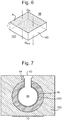
- Figure 6 depicts schematically heat transferring into and out from the second material 160.
- the thermal load which may be positive or negative, transferred from the channel 46 to the second material 160 is referenced by Q in .
- the thermal load which may be positive or negative, transferred from the second material 160 to the first material 100 is referenced by Q out .
- the thickness of the second material 160 between the channel 46 and the first material 100 is referenced by t.
- the surface area of the second material 160 facing the channel 46 is referenced by A.
- the second material 160 has a thermal conductivity at 25°C of ⁇ .
- the heat capacity C p is measured in JK -1 .
- the specific heat capacity C specific is measured in Jkg -1 K -1 .
- the time constant ⁇ is related to the delay between a thermal load at the channel 46 and the associated temperature change at the substrate table WT, for example.
- a thermal load variation occurring inside the channel 46 that is transferred through into the first material 100 of the substrate holder 30 may be described by a heat transfer function H(f), where f is the frequency of heat variations within the channel 46.
- the magnitude of H(f) is an indication of how much the thermal load variation is reduced by the second material 160.
- the thermal load variation reduction factor may be termed X, where
- 1/X.
- the thermal load variation reduction factor X is the factor by which the invention reduces thermal load variations relative to if the second material 160 were not provided.
- the reference point for the thermal load variation reduction factor X is a channel 46 that is not provided with the second material 160. It is desirable for the thermal load variation reduction factor to be high. Hence it is desirable for X -1 to be low.
- the heat transfer function H(f) is related to the time constant ⁇ by the following equation
- (f 2 ⁇ 2 +1 2 ) -1/2 , where f is the frequency of the thermal load variation and i is the imaginary unit ⁇ 1 .
- the frequency f of the thermal load variation is a property of how the lithographic apparatus is used.
- Thermal load variations in the channel 46 at the edge of the substrate W may be caused by gas flow variations through the openings 42 and the passageway 44. Such gas flow variations may be caused by the liquid confinement structure IH crossing the gap 5 at the edge of the substrate W. The time constant associated with such crossings defines the frequency f of the thermal load variations.
- the thicker the second material 160 the greater the reduction in thermal load variations.
- the thickness t of the second material 160 is at most about 1 mm.
- the thickness t of the second material 160 required to achieve a set thermal load variation reduction factor X can be reduced.
- the second material 160 is poly p-xylylene polymer
- the thickness t of the second material 160 can be reduced compared to if the second material 160 were PTFE, glass or ceramic, while achieving the same thermal load variation reduction.
- the second material 160 has a thickness t of at least 200 ⁇ m.
- a minimum level of thermal load variation reduction is achieved.
- the second material 160 is poly p-xylylene polymer
- a thermal load variation reduction factor X of at least 2 is achieved.
- the thermal load variation reduction factor X is a measure of the reduction in thermal load variation achieved by the invention. The reduction is measured relative to an arrangement in which the second material 160 is not provided.
- the second material 160 has a thickness t of at least 350 ⁇ m.
- a thermal load variation reduction factor X is achieved.
- the thermal load variation reduction factor X is a measure of the reduction in thermal load variation achieved by the invention. The reduction is measured relative to an arrangement in which the second material 160 is not provided.
- the second material 160 is between substantially all of the channel 46 and the first material 100. This means that the second material 160 lines the whole of the channel 46. However, this need not necessarily be the case. In an embodiment, the second material 160 is between only a part of the channel 46 and the first material 100. For example, in an embodiment only the area most affected by the gas flows that impart a thermal load are provided with the second material 160. For example, in an embodiment the second material 160 is between the bottom of the channel 46 and the first material, but not between the sides or top of the channel 46 and the first material. At the sides and the top of the channel 46, the channel 46 may be directly adjacent the first material 100 without the second material 160 between. It is more important for the second material 160 to be at the bottom of the channel 46 so as to intercept thermal loads that would otherwise reach the first material 100 directly from the opening 42, for example. In an embodiment the second material 160 is provided at the openings 42 and the passageway 44.
- the lithographic apparatus comprises an object table e.g. a substrate table WT formed from the block of the first material 100.
- the object table comprises an object holder e.g. substrate holder 30 to hold an object e.g. substrate W.
- the object table comprises an opening 42 adjacent an edge of the substrate holder.
- the channel 46 is in fluid communication with the opening 42 via the object table.
- the lithographic apparatus comprises a liquid confinement structure IH.
- the liquid confinement structure IH is configured to confine immersion fluid in a localised region between a final element of the projection system PS and a surface of a substrate W.
- the fluid confinement structure is formed from the block of the first material 100.
- the liquid confinement structure IH comprises an opening in fluid communication with the channel associated with the outlet 14, which is depicted in Figure 2 .
- Figure 7 depicts in cross-section a part of a lithographic apparatus according to an embodiment of the invention.
- the lithographic apparatus comprises a third material 90.
- the third material 90 is between the second material 160 and the channel 46.
- the third material 90 has a thermal conductivity higher than that of the second material 160.
- the third material 90 having a thermal conductivity higher than that of the second material 160, thermal load variations on the substrate holder 30 caused by the two phase flow in the channel 46 can be reduced.
- the third material 90 is a solid material.
- the third material 90 has an effect of spreading a head load from the channel 46 across the third material 90.
- the third material 90 spreads spatially within itself the thermal load caused by e.g. evaporation within the two phase flow.
- the thermal load is more spatially spread when it is transferred to the second material 160. This means that the effect of the second material 160 acting as a heat shield and/or as a heat buffer is used more effectively. This is explained further with reference to Figure 8 and Figure 9 .
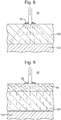
- Figure 8 depicts a part of a lithographic apparatus according to an embodiment of the present disclosure.
- no third material 90 is provided between the second material 160 and the channel 46.
- the large arrow at the top of Figure 8 represents a flow of gas in the channel 46 directed towards a particular thermal load point 92 at the interface between the channel 46 and the second material 160.
- the thermal load may be caused by evaporation of liquid in the two phase flow within the channel 46 for example.
- the thermal load is concentrated at the thermal load point 92.
- the thermal load is transferred through the thickness of the second material 160.
- the thermal load is spread out spatially but only to a limited extent.
- the dashed lines shown in Figure 8 represent the spatial extent of the thermal load variations within the second material 160. As such, the thermal load variations remain to a large extent concentrated spatially within the second material 160.
- the limited spatial extent of the thermal variations within the second material 160 limits the effectiveness of the second material 160 in reducing thermal load variations at the first material 100.
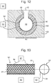
- Figure 9 depicts in cross-section a part of a lithographic apparatus according to an embodiment of the invention.
- the third material 90 is provided between the channel 46 and the second material 160.
- a thermal load from the channel 46 is concentrated at a thermal load point 92 at the interface between the channel 46 and the third material 90.
- the thermal load is spread spatially to a great extent within the third material 90.
- the high thermal conductivity third material 90 improves the effectiveness of the second material 160 in reducing thermal load variations reaching the first material 100.
- the gas flow that provides a thermal load at the thermal load point 92 may be a gas flow directed from the opening 42 via the passageway 44.
- approximately 90%, for example, of the thermal load due to the gas flow at the thermal load point 92 may be expected to be transferred through the second material 160 as depicted in Figure 8 .
- the figure of 90% is an estimate. Depending on the arrangement and use of the lithographic apparatus, the figure may be closer to 50%, for example.
- the remaining 10% of the thermal load may be expected to be transferred through the channel 46, from where it may transfer through an extraction hole, for example.
- the third material 90 is provided between the second material 160 and the channel 46 the percentage of the thermal load from the thermal load point 92 that is transferred directly through the second material 160 may be reduced to about 60%. In this case the remaining 40% may be transferred along the channel 46. Hence, the thermal load is spread out spatially by the third material 90.
- the third material 90 desirably has a high thermal conductivity.
- the third material 90 is a metal.
- the third material 90 is selected from a group consisted of stainless steel, copper, silver, gold and platinum.
- the third material 90 is not particularly limited provided that it has a higher thermal conductivity than the second material 160.
- any metal may be used as the third material 90.
- the thermal conductivity of the third material 90 is at least one order of magnitude higher than that of the second material 160.
- Other materials may be used for the third material 90.
- the third material 90 is silicon infiltrated silicon carbide (SiSiC).
- the thickness of the third material 90 is at most 100 ⁇ m. By providing that the thickness of the third material 90 is at most 100 ⁇ m, the amount of third material 90 required is relatively small and the third material 90 takes up relatively little space within the system.
- the thickness of the third material 90 is at least 10 ⁇ m. By providing that the thickness of the third material 90 is at least 10 ⁇ m, the third material 90 is easier to apply between the second material 160 and the channel 46.
- the third material 90 is continuous.
- the third material 90 may be a continuous layer between the second material 160 and the channel 46.
- the third material 90 may be applied as a liquid or gel, which solidifies into a continuous layer of the third material 90.
- a liquid or gel may be applied by inserting the liquid through one or more openings into the channel 46.
- extraction holes from the base of the channel 46 and/or the openings 42 at the upper end of the channel 46 may be used to apply liquid or gel so as to form the third material 90.
- Figure 10 depicts a side view and a front view of the third material 90 according to an embodiment of the invention.
- the third material 90 is formed as a mesh or a network of connected pieces 91 of the third material 90.
- the third material 90 only covers a part of the inner side of the second material 160.
- the third material 90 has a mesh structure.
- the third material 90 has a cylindrical form, as depicted in Figure 10 , for example. Desirably, the third material 90 has a form and shape that allows it to cover the inner side of the whole of the second material 160.
- third material 90 is discontinuous, for example having a mesh structure, the third material 90 effectively spreads the thermal load.
- a mesh of third material is equally as effective as a continuous layer of third material 90 (for a given overall volume of third material 90).
- the third material 90 is formed as a mesh or a network of connected pieces 91 of the third material 90
- the third material 90 can be inserted into the channel 46 in a similar fashion to the way in which a stent is inserted into a blood vessel during medical surgery.
- connected pieces 91 of the third material 90 may be mounted onto an inflatable balloon.
- the third material 90 mounted on the inflatable balloon may be inserted into the channel 46.
- the third material 90 may then be deposited between the second material 160 and the channel 46.
- the third material 90 may be deposited by inflating the inflatable balloon.
- Figure 11 depicts in cross-section a part of a lithographic apparatus according to an embodiment of the invention.
- the third material 90 is provided as a mesh or a network of connected pieces 91 of the third material 90.
- a gas flow causing a thermal load may be incidence on the thermal load point 92 at the interface between the channel 46 and the third material 90.
- the thermal load is spread by the high thermal conductivity third material 90. Following the spreading, the thermal load is transferred through the second material 160.
- the second material 160 has a property of heat resistance and/or a property of heat capacity, thereby reducing thermal load variations that reach the first material 100.
- the channel 46 is formed within a block that comes in two or more pieces.
- the sides and bottom of the channel 46 may be formed by a separate piece of the block from the piece of the block that forms the top of the channel 46.
- the two or more pieces may be glued together so as to form the channel 46 within the block.
- the second material 160 and/or the third material 90 may be provided before the two pieces of the block are connected together.
- An advantage of inserting the second material 160 and/or the third material 90 through openings in fluid communication with the channel 46 is that the second material 160 and/or the third material 90 can be provided after the channel 46 has been formed within the block. This means that it is not necessary for the block to be made in two or more pieces. Connecting two or more pieces of the block together so as to form the channel can require the temperature of the block and the channel 46 to be raised to a temperature that the second material 160 may not be able to withstand.
- PTFE and poly p-xylylene polymer cannot withstand very high temperatures.
- glass and porcelain ceramic can withstand very high temperatures. Hence glass or porcelain ceramic may be provided before connecting two or more pieces of the block together so as to form the channel 46.
- the third material 90 it is not necessary for the third material 90 to be provided. Even when the third material 90 is not provided, by providing that the second material 160 satisfies ⁇ / ⁇ C specific ⁇ 1x10 -7 m 2 s -1 , the second material 160 acts as a thermal buffer that reduces thermal load variations compared to systems in which the second material does not satisfy ⁇ / ⁇ C specific ⁇ 1x10 -7 m 2 s -1 .
- the second material 160 It is not necessary for the second material 160 to satisfy ⁇ / ⁇ C specific ⁇ 1x10 -6 m 2 s -1 .
- the third material 90 spreads the thermal load spatially across the second material 160, thereby reducing thermal load variations.
- the second material 160 has a specific heat capacity higher than that of the first material 100.
- the second material 160 acts as a thermal buffer. The thermal buffer can partially store thermal variations from the channel 46 before transferring any thermal load to the first material 100. Accordingly, the dynamic thermal load variations are reduced.
- the second material 160 it is not necessary for the second material 160 to have a specific heat capacity higher than that of the first material 100.
- the second material 160 has a thermal conductivity lower than that of the first material 100. By providing that the second material 160 has a thermal conductivity lower than that of the first material 100, the second material 160 provides heat resistance between the channel 46 and the first material 100.
- the third material 90 is formed as a heater.
- the heater comprises the third material 90.
- the third material 90 is configured to function as the heating element of the heater.
- the heater is an electric heater.
- the third material 90 is electrically connected to a heater power source 93.
- the heater power source 93 is configured to provide an electric current to the third material 90.
- the electric current passes through the third material 90.
- the electrical energy from the electric current is converted into heat energy in the third material 90.
- the third material 90 is connected to the heater power source 93 by electric leads 94.
- the material used for the electric leads is not particularly limited.
- the electric leads 94 are conductors of electricity.
- the electric leads 94 are formed from a metal such as copper.
- the third material 90 is formed as a mesh or a network of connected pieces 91 of the third material 90.
- the two-dimensional mesh is a heater.
- the third material 90 is not necessary for the third material 90 to be formed as a mesh or a network in order for the third material 90 to be formed as a heater. As depicted in Figure 12 , in an embodiment the third material 90 is continuous and is formed as a heater.
- the third material 90 has a circular diameter. Accordingly, when the third material 90 is formed as a heater, the heater is folded into a circular diameter. The third material 90 is surrounded by the second material 160. The second material 160 is a heat-isolator material. Accordingly, when the third material 90 is formed as a heater, the heater is surrounded by a heat-isolator material.
- the lithographic apparatus comprises a thermal controller 95.
- the thermal controller 95 is configured to control the heater so as to locally compensate for a thermal load of the two phase flow.
- the two phase flow passes through the channel 46.
- a thermal load generated inside the channel 46 can be locally compensated by control of the heater.
- a cold load generated by evaporation inside the channel 46 can be locally compensated by control of the heater.
- the second material 160 is configured to reduce any remaining thermal load (which is not compensated for by control of the heater) directly entering the first material 100.
- the third material 90 has high thermal conductivity and functions as a heater.
- the high thermal conductivity of the third material 90 allows a thermal load in the channel 46 to spread through the third material 90.
- the function of the third material 90 as a heat spreader is a passive function.
- the third material 90 functions as a heater to locally compensate for a thermal load in the channel 46.
- the function of the third material 90 as a heater is an active function.
- An evaporation heat load inside the channel 46 is spread at the third material 90 and is also compensated for by active heating. In an embodiment the active heating is performed via copper wires.
- the second material 160 functions as a heat isolator and as a heat buffer.
- the second material 160 reduces the effect that a heat load in the channel 46 has on the first material 100 of the substrate table WT.
- the third material 90 is formed as a segmented heater.
- the third material 90 is electrically connected to a plurality of heater power sources 93.
- Each heater power source 93 is configured to provide an electric current to a respective segment of the third material 90. The electric current passes through the respective segment of the third material 90. The electrical energy from the electric current is converted into heat energy in the respective segment of the third material 90.
- Each segment of the third material 90 functions as a heater substantially independently of the other segments of the third material 90.
- the number of segments is not particularly limited. By dividing the third material 90 into more segments, a spatially distributed thermal load can be compensated for more effectively.
- a further refinement is illustrated in Figure 5 .
- the further refinement may be applied to any other embodiment.
- the further refinement may be applied to only the first drain 10, only the second drain 20 or to both the first and second drains 10, 20.
- the refinement is the same as that described in United States patent application publication no. US 2008/0297744 .
- a liquid supply device configured actively to supply a liquid to the drain 10, 20 independent of the position of the substrate table WT is provided.
- the supply of a liquid (through channel 200) can result in a decrease in the amount of evaporation in the drain 10, 20. The way this is accomplished can be viewed in two separate ways.
- lithographic apparatus in the manufacture of ICs
- the lithographic apparatus described herein may have other applications, such as the manufacture of integrated optical systems, guidance and detection patterns for magnetic domain memories, flat-panel displays, liquid-crystal displays (LCDs), thin-film magnetic heads, etc.
- LCDs liquid-crystal displays
- any use of the terms “wafer” or “die” herein may be considered as synonymous with the more general terms “substrate” or "target portion”, respectively.
- the substrate referred to herein may be processed, before or after exposure, in for example a track (a tool that typically applies a layer of resist to a substrate and develops the exposed resist), a metrology tool and/or an inspection tool. Where applicable, the disclosure herein may be applied to such and other substrate processing tools. Further, the substrate may be processed more than once, for example in order to create a multi-layer IC, so that the term substrate used herein may also refer to a substrate that already contains multiple processed layers.
- UV radiation e.g. having a wavelength of or about 365, 248, 193, 157 or 126 nm
- EUV radiation e.g. having a wavelength in the range of 5-20 nm
- particle beams such as ion beams or electron beams.
- lens may refer to any one or combination of various types of optical components, including refractive, reflective, magnetic, electromagnetic and electrostatic optical components.
Claims (14)
- Un appareil lithographique à immersion comprenant :un canal (46) destiné à l'extraction et au passage à travers celui-ci d'un écoulement diphasique, dans lequel le canal est formé au sein d'un bloc (30), le bloc étant d'un premier matériau (100) ;un deuxième matériau (160) entre le premier matériau et le canal, dans lequel le deuxième matériau a une capacité calorifique spécifique supérieure à celle du premier matériau et/ou une conductivité thermique inférieure à celle du premier matériau ; etun troisième matériau (90) entre le deuxième matériau et le canal,caractérisé en ce que le troisième matériau a une conductivité thermique supérieure à celle du deuxième matériau.
- L'appareil lithographique à immersion de la revendication 1, dans lequel le deuxième matériau satisfait λ/(ρCspécifique) ≤ 1x10⁻⁶ m2s-1, où A est une conductivité thermique du deuxième matériau en Wm-1K-1, ρ est une masse volumique du deuxième matériau en kgm-3 et Cspécifique est une capacité calorifique spécifique du deuxième matériau en Jkg-1K-1.
- L'appareil lithographique à immersion de la revendication 1 ou de la revendication 2, dans lequel le deuxième matériau est sélectionné dans un groupe constitué de polymère de poly(p-xylylène), de PTFE, de verre et de céramique.
- L'appareil lithographique à immersion de la revendication 1, de la revendication 2 ou de la revendication 3, dans lequel le deuxième matériau comprend du polymère de poly(p-xylylène).
- L'appareil lithographique à immersion de n'importe lesquelles des revendications 1 à 4, dans lequel le troisième matériau est sélectionné dans un groupe constitué d'acier inoxydable, de cuivre, d'argent, d'or, de platine et de carbure de silicium infiltré de silicium.
- L'appareil lithographique à immersion de n'importe lesquelles des revendications 1 à 5, dans lequel le troisième matériau est continu, ou formé comme un maillage ou un réseau de fragments raccordés du troisième matériau, ou formé comme un élément chauffant.
- L'appareil lithographique à immersion de la revendication 6, comprenant en sus un contrôleur thermique (95) configuré afin de contrôler l'élément chauffant de manière à compenser localement une charge thermique de l'écoulement diphasique.
- L'appareil lithographique à immersion de n'importe lesquelles des revendications 1 à 7, dans lequel le deuxième matériau a une épaisseur d'au moins 200 µm.
- L'appareil lithographique à immersion de n'importe lesquelles des revendications 1 à 8, dans lequel le deuxième matériau a une épaisseur d'au moins 350 µm.
- L'appareil lithographique à immersion de n'importe lesquelles des revendications 1 à 9, comprenant une table porte-objet (WT) formée à partir du bloc du premier matériau, dans lequel la table porte-objet comprend :un porte-objet (30) pour porter un objet (W) ; etun orifice (42) adjacent à un bord du porte-objet, dans lequel le canal est en communication fluidique avec l'orifice via la table porte-objet.
- L'appareil lithographique à immersion de n'importe lesquelles des revendications 1 à 10, comprenant une structure de confinement de fluide (IH) configurée afin de confiner du fluide d'immersion dans une région localisée (11) entre un organe final d'un système de projection (PS) et une surface d'un substrat (W), dans lequel la structure de confinement de fluide est formée à partir du bloc du premier matériau et comprend un orifice en communication fluidique avec le canal.
- Un procédé de fabrication d'un appareil lithographique à immersion, le procédé comprenant le fait :de fournir un bloc d'un premier matériau au sein duquel est formé un canal ;de prévoir l'extraction et le passage d'un écoulement diphasique à travers le canal ;de fournir entre le premier matériau et le canal un deuxième matériau, dans lequel le deuxième matériau a une capacité calorifique spécifique supérieure à celle du premier matériau et/ou une conductivité thermique inférieure à celle du premier matériau ; etde fournir entre le deuxième matériau et le canal un troisième matériau, dans lequel le troisième matériau a une conductivité thermique supérieure à celle du deuxième matériau.
- Le procédé de la revendication 12, dans lequel le fait de fournir le troisième matériau comprend le fait :de monter des fragments raccordés (91) du troisième matériau sur un ballon gonflable ;d'insérer le troisième matériau monté sur le ballon gonflable dans le canal ; etde déposer le troisième matériau entre le deuxième matériau et le canal.
- Le procédé de la revendication 12 ou de la revendication 13, dans lequel le fait de fournir le deuxième matériau comprend le fait d'insérer le deuxième matériau à travers un orifice dans le bloc qui est en communication fluidique avec le canal.
Applications Claiming Priority (3)
| Application Number | Priority Date | Filing Date | Title |
|---|---|---|---|
| EP14171800 | 2014-06-10 | ||
| EP15159551 | 2015-03-18 | ||
| PCT/EP2015/060039 WO2015188988A1 (fr) | 2014-06-10 | 2015-05-07 | Appareil lithographique et procédé de fabrication d'appareil lithographique |
Publications (2)
| Publication Number | Publication Date |
|---|---|
| EP3155481A1 EP3155481A1 (fr) | 2017-04-19 |
| EP3155481B1 true EP3155481B1 (fr) | 2019-04-24 |
Family
ID=53059104
Family Applications (1)
| Application Number | Title | Priority Date | Filing Date |
|---|---|---|---|
| EP15721224.2A Active EP3155481B1 (fr) | 2014-06-10 | 2015-05-07 | Appareil lithographique et procédé de fabrication d'appareil lithographique |
Country Status (7)
| Country | Link |
|---|---|
| US (1) | US10018926B2 (fr) |
| EP (1) | EP3155481B1 (fr) |
| JP (1) | JP6371865B2 (fr) |
| KR (1) | KR102013249B1 (fr) |
| CN (1) | CN106462082B (fr) |
| NL (1) | NL2014773A (fr) |
| WO (1) | WO2015188988A1 (fr) |
Families Citing this family (2)
| Publication number | Priority date | Publication date | Assignee | Title |
|---|---|---|---|---|
| KR102054322B1 (ko) | 2012-05-29 | 2019-12-10 | 에이에스엠엘 네델란즈 비.브이. | 대상물 홀더 및 리소그래피 장치 |
| JP7413112B2 (ja) * | 2020-03-24 | 2024-01-15 | 東京エレクトロン株式会社 | 基板載置台及び基板処理装置 |
Family Cites Families (16)
| Publication number | Priority date | Publication date | Assignee | Title |
|---|---|---|---|---|
| US20050099611A1 (en) * | 2002-06-20 | 2005-05-12 | Nikon Corporation | Minimizing thermal distortion effects on EUV mirror |
| JP3977324B2 (ja) | 2002-11-12 | 2007-09-19 | エーエスエムエル ネザーランズ ビー.ブイ. | リソグラフィ装置 |
| EP1420298B1 (fr) | 2002-11-12 | 2013-02-20 | ASML Netherlands B.V. | Appareil lithographique |
| US7213963B2 (en) | 2003-06-09 | 2007-05-08 | Asml Netherlands B.V. | Lithographic apparatus and device manufacturing method |
| WO2005006418A1 (fr) * | 2003-07-09 | 2005-01-20 | Nikon Corporation | Dispositif d'exposition et procede de fabrication |
| JP4543767B2 (ja) * | 2004-06-10 | 2010-09-15 | 株式会社ニコン | 露光装置及びデバイス製造方法 |
| JP5119666B2 (ja) * | 2004-06-21 | 2013-01-16 | 株式会社ニコン | 露光装置、液体除去方法、及びデバイス製造方法 |
| US7304715B2 (en) * | 2004-08-13 | 2007-12-04 | Asml Netherlands B.V. | Lithographic apparatus and device manufacturing method |
| US8514365B2 (en) | 2007-06-01 | 2013-08-20 | Asml Netherlands B.V. | Lithographic apparatus and device manufacturing method |
| US20100045949A1 (en) | 2008-08-11 | 2010-02-25 | Nikon Corporation | Exposure apparatus, maintaining method and device fabricating method |
| US8004688B2 (en) * | 2008-11-26 | 2011-08-23 | Zygo Corporation | Scan error correction in low coherence scanning interferometry |
| NL2004362A (en) * | 2009-04-10 | 2010-10-12 | Asml Netherlands Bv | A fluid handling device, an immersion lithographic apparatus and a device manufacturing method. |
| JP2010287665A (ja) | 2009-06-10 | 2010-12-24 | Canon Inc | 露光装置、及びそれを用いたデバイスの製造方法 |
| EP2365390A3 (fr) * | 2010-03-12 | 2017-10-04 | ASML Netherlands B.V. | Appareil et procédé lithographique |
| KR102054322B1 (ko) * | 2012-05-29 | 2019-12-10 | 에이에스엠엘 네델란즈 비.브이. | 대상물 홀더 및 리소그래피 장치 |
| CN104412164B (zh) * | 2012-05-29 | 2017-09-12 | Asml荷兰有限公司 | 支撑装置、光刻装置和器件制造方法 |
-
2015
- 2015-05-07 JP JP2016572686A patent/JP6371865B2/ja active Active
- 2015-05-07 KR KR1020177000632A patent/KR102013249B1/ko active IP Right Grant
- 2015-05-07 US US15/314,841 patent/US10018926B2/en active Active
- 2015-05-07 CN CN201580031089.0A patent/CN106462082B/zh active Active
- 2015-05-07 NL NL2014773A patent/NL2014773A/en unknown
- 2015-05-07 EP EP15721224.2A patent/EP3155481B1/fr active Active
- 2015-05-07 WO PCT/EP2015/060039 patent/WO2015188988A1/fr active Application Filing
Non-Patent Citations (1)
| Title |
|---|
| None * |
Also Published As
| Publication number | Publication date |
|---|---|
| CN106462082B (zh) | 2018-05-18 |
| US20180067398A1 (en) | 2018-03-08 |
| JP6371865B2 (ja) | 2018-08-08 |
| US10018926B2 (en) | 2018-07-10 |
| WO2015188988A1 (fr) | 2015-12-17 |
| CN106462082A (zh) | 2017-02-22 |
| JP2017523449A (ja) | 2017-08-17 |
| NL2014773A (en) | 2016-03-31 |
| EP3155481A1 (fr) | 2017-04-19 |
| KR102013249B1 (ko) | 2019-08-22 |
| KR20170016476A (ko) | 2017-02-13 |
Similar Documents
| Publication | Publication Date | Title |
|---|---|---|
| EP1921505B1 (fr) | Appareil de lithographie et procédé de fabrication d'un dispositif | |
| TWI574117B (zh) | 支撐裝置、微影裝置及器件製造方法 | |
| KR101533014B1 (ko) | 정전기 클램프, 리소그래피 장치, 및 정전기 클램프를 제조하는 방법 | |
| EP3137945B1 (fr) | Table de support pour appareil lithographique, appareil lithographique et procédé de fabrication de dispositif | |
| TW201235792A (en) | Lithographic apparatus and method | |
| TWI421644B (zh) | 微影裝置及方法 | |
| EP3155481B1 (fr) | Appareil lithographique et procédé de fabrication d'appareil lithographique | |
| US10571810B2 (en) | Substrate table, a lithographic apparatus and a method of operating a lithographic apparatus | |
| JP6387421B2 (ja) | リソグラフィ装置及びデバイス製造方法 | |
| EP3455677A1 (fr) | Corps d'extraction pour appareil lithographique | |
| US20230095108A1 (en) | Method for preparing a substrate and lithographic apparatus | |
| WO2021094057A1 (fr) | Support de substrat, appareil de lithographie, procédé pour manipuler la distribution de charge et procédé de préparation d'un substrat | |
| JP2007053377A (ja) | リソグラフィー装置およびデバイス製造方法 |
Legal Events
| Date | Code | Title | Description |
|---|---|---|---|
| STAA | Information on the status of an ep patent application or granted ep patent |
Free format text: STATUS: THE INTERNATIONAL PUBLICATION HAS BEEN MADE |
|
| PUAI | Public reference made under article 153(3) epc to a published international application that has entered the european phase |
Free format text: ORIGINAL CODE: 0009012 |
|
| STAA | Information on the status of an ep patent application or granted ep patent |
Free format text: STATUS: REQUEST FOR EXAMINATION WAS MADE |
|
| 17P | Request for examination filed |
Effective date: 20161114 |
|
| AK | Designated contracting states |
Kind code of ref document: A1 Designated state(s): AL AT BE BG CH CY CZ DE DK EE ES FI FR GB GR HR HU IE IS IT LI LT LU LV MC MK MT NL NO PL PT RO RS SE SI SK SM TR |
|
| AX | Request for extension of the european patent |
Extension state: BA ME |
|
| DAV | Request for validation of the european patent (deleted) | ||
| DAX | Request for extension of the european patent (deleted) | ||
| GRAP | Despatch of communication of intention to grant a patent |
Free format text: ORIGINAL CODE: EPIDOSNIGR1 |
|
| STAA | Information on the status of an ep patent application or granted ep patent |
Free format text: STATUS: GRANT OF PATENT IS INTENDED |
|
| INTG | Intention to grant announced |
Effective date: 20181212 |
|
| GRAS | Grant fee paid |
Free format text: ORIGINAL CODE: EPIDOSNIGR3 |
|
| GRAA | (expected) grant |
Free format text: ORIGINAL CODE: 0009210 |
|
| STAA | Information on the status of an ep patent application or granted ep patent |
Free format text: STATUS: THE PATENT HAS BEEN GRANTED |
|
| AK | Designated contracting states |
Kind code of ref document: B1 Designated state(s): AL AT BE BG CH CY CZ DE DK EE ES FI FR GB GR HR HU IE IS IT LI LT LU LV MC MK MT NL NO PL PT RO RS SE SI SK SM TR |
|
| REG | Reference to a national code |
Ref country code: GB Ref legal event code: FG4D |
|
| REG | Reference to a national code |
Ref country code: CH Ref legal event code: EP |
|
| REG | Reference to a national code |
Ref country code: AT Ref legal event code: REF Ref document number: 1124835 Country of ref document: AT Kind code of ref document: T Effective date: 20190515 Ref country code: IE Ref legal event code: FG4D |
|
| REG | Reference to a national code |
Ref country code: DE Ref legal event code: R096 Ref document number: 602015028846 Country of ref document: DE |
|
| REG | Reference to a national code |
Ref country code: NL Ref legal event code: MP Effective date: 20190424 |
|
| REG | Reference to a national code |
Ref country code: LT Ref legal event code: MG4D |
|
| PG25 | Lapsed in a contracting state [announced via postgrant information from national office to epo] |
Ref country code: NL Free format text: LAPSE BECAUSE OF FAILURE TO SUBMIT A TRANSLATION OF THE DESCRIPTION OR TO PAY THE FEE WITHIN THE PRESCRIBED TIME-LIMIT Effective date: 20190424 |
|
| PG25 | Lapsed in a contracting state [announced via postgrant information from national office to epo] |
Ref country code: HR Free format text: LAPSE BECAUSE OF FAILURE TO SUBMIT A TRANSLATION OF THE DESCRIPTION OR TO PAY THE FEE WITHIN THE PRESCRIBED TIME-LIMIT Effective date: 20190424 Ref country code: LT Free format text: LAPSE BECAUSE OF FAILURE TO SUBMIT A TRANSLATION OF THE DESCRIPTION OR TO PAY THE FEE WITHIN THE PRESCRIBED TIME-LIMIT Effective date: 20190424 Ref country code: ES Free format text: LAPSE BECAUSE OF FAILURE TO SUBMIT A TRANSLATION OF THE DESCRIPTION OR TO PAY THE FEE WITHIN THE PRESCRIBED TIME-LIMIT Effective date: 20190424 Ref country code: NO Free format text: LAPSE BECAUSE OF FAILURE TO SUBMIT A TRANSLATION OF THE DESCRIPTION OR TO PAY THE FEE WITHIN THE PRESCRIBED TIME-LIMIT Effective date: 20190724 Ref country code: FI Free format text: LAPSE BECAUSE OF FAILURE TO SUBMIT A TRANSLATION OF THE DESCRIPTION OR TO PAY THE FEE WITHIN THE PRESCRIBED TIME-LIMIT Effective date: 20190424 Ref country code: PT Free format text: LAPSE BECAUSE OF FAILURE TO SUBMIT A TRANSLATION OF THE DESCRIPTION OR TO PAY THE FEE WITHIN THE PRESCRIBED TIME-LIMIT Effective date: 20190824 Ref country code: AL Free format text: LAPSE BECAUSE OF FAILURE TO SUBMIT A TRANSLATION OF THE DESCRIPTION OR TO PAY THE FEE WITHIN THE PRESCRIBED TIME-LIMIT Effective date: 20190424 Ref country code: SE Free format text: LAPSE BECAUSE OF FAILURE TO SUBMIT A TRANSLATION OF THE DESCRIPTION OR TO PAY THE FEE WITHIN THE PRESCRIBED TIME-LIMIT Effective date: 20190424 |
|
| PG25 | Lapsed in a contracting state [announced via postgrant information from national office to epo] |
Ref country code: GR Free format text: LAPSE BECAUSE OF FAILURE TO SUBMIT A TRANSLATION OF THE DESCRIPTION OR TO PAY THE FEE WITHIN THE PRESCRIBED TIME-LIMIT Effective date: 20190725 Ref country code: RS Free format text: LAPSE BECAUSE OF FAILURE TO SUBMIT A TRANSLATION OF THE DESCRIPTION OR TO PAY THE FEE WITHIN THE PRESCRIBED TIME-LIMIT Effective date: 20190424 Ref country code: BG Free format text: LAPSE BECAUSE OF FAILURE TO SUBMIT A TRANSLATION OF THE DESCRIPTION OR TO PAY THE FEE WITHIN THE PRESCRIBED TIME-LIMIT Effective date: 20190724 Ref country code: LV Free format text: LAPSE BECAUSE OF FAILURE TO SUBMIT A TRANSLATION OF THE DESCRIPTION OR TO PAY THE FEE WITHIN THE PRESCRIBED TIME-LIMIT Effective date: 20190424 Ref country code: PL Free format text: LAPSE BECAUSE OF FAILURE TO SUBMIT A TRANSLATION OF THE DESCRIPTION OR TO PAY THE FEE WITHIN THE PRESCRIBED TIME-LIMIT Effective date: 20190424 |
|
| REG | Reference to a national code |
Ref country code: DE Ref legal event code: R119 Ref document number: 602015028846 Country of ref document: DE |
|
| REG | Reference to a national code |
Ref country code: AT Ref legal event code: MK05 Ref document number: 1124835 Country of ref document: AT Kind code of ref document: T Effective date: 20190424 |
|
| REG | Reference to a national code |
Ref country code: CH Ref legal event code: PL |
|
| PG25 | Lapsed in a contracting state [announced via postgrant information from national office to epo] |
Ref country code: IS Free format text: LAPSE BECAUSE OF FAILURE TO SUBMIT A TRANSLATION OF THE DESCRIPTION OR TO PAY THE FEE WITHIN THE PRESCRIBED TIME-LIMIT Effective date: 20190824 |
|
| PG25 | Lapsed in a contracting state [announced via postgrant information from national office to epo] |
Ref country code: DK Free format text: LAPSE BECAUSE OF FAILURE TO SUBMIT A TRANSLATION OF THE DESCRIPTION OR TO PAY THE FEE WITHIN THE PRESCRIBED TIME-LIMIT Effective date: 20190424 Ref country code: AT Free format text: LAPSE BECAUSE OF FAILURE TO SUBMIT A TRANSLATION OF THE DESCRIPTION OR TO PAY THE FEE WITHIN THE PRESCRIBED TIME-LIMIT Effective date: 20190424 Ref country code: EE Free format text: LAPSE BECAUSE OF FAILURE TO SUBMIT A TRANSLATION OF THE DESCRIPTION OR TO PAY THE FEE WITHIN THE PRESCRIBED TIME-LIMIT Effective date: 20190424 Ref country code: LI Free format text: LAPSE BECAUSE OF NON-PAYMENT OF DUE FEES Effective date: 20190531 Ref country code: MC Free format text: LAPSE BECAUSE OF FAILURE TO SUBMIT A TRANSLATION OF THE DESCRIPTION OR TO PAY THE FEE WITHIN THE PRESCRIBED TIME-LIMIT Effective date: 20190424 Ref country code: SK Free format text: LAPSE BECAUSE OF FAILURE TO SUBMIT A TRANSLATION OF THE DESCRIPTION OR TO PAY THE FEE WITHIN THE PRESCRIBED TIME-LIMIT Effective date: 20190424 Ref country code: CH Free format text: LAPSE BECAUSE OF NON-PAYMENT OF DUE FEES Effective date: 20190531 Ref country code: RO Free format text: LAPSE BECAUSE OF FAILURE TO SUBMIT A TRANSLATION OF THE DESCRIPTION OR TO PAY THE FEE WITHIN THE PRESCRIBED TIME-LIMIT Effective date: 20190424 Ref country code: CZ Free format text: LAPSE BECAUSE OF FAILURE TO SUBMIT A TRANSLATION OF THE DESCRIPTION OR TO PAY THE FEE WITHIN THE PRESCRIBED TIME-LIMIT Effective date: 20190424 |
|
| REG | Reference to a national code |
Ref country code: BE Ref legal event code: MM Effective date: 20190531 |
|
| PG25 | Lapsed in a contracting state [announced via postgrant information from national office to epo] |
Ref country code: LU Free format text: LAPSE BECAUSE OF NON-PAYMENT OF DUE FEES Effective date: 20190507 Ref country code: IT Free format text: LAPSE BECAUSE OF FAILURE TO SUBMIT A TRANSLATION OF THE DESCRIPTION OR TO PAY THE FEE WITHIN THE PRESCRIBED TIME-LIMIT Effective date: 20190424 Ref country code: SM Free format text: LAPSE BECAUSE OF FAILURE TO SUBMIT A TRANSLATION OF THE DESCRIPTION OR TO PAY THE FEE WITHIN THE PRESCRIBED TIME-LIMIT Effective date: 20190424 |
|
| PLBE | No opposition filed within time limit |
Free format text: ORIGINAL CODE: 0009261 |
|
| STAA | Information on the status of an ep patent application or granted ep patent |
Free format text: STATUS: NO OPPOSITION FILED WITHIN TIME LIMIT |
|
| GBPC | Gb: european patent ceased through non-payment of renewal fee |
Effective date: 20190724 |
|
| PG25 | Lapsed in a contracting state [announced via postgrant information from national office to epo] |
Ref country code: TR Free format text: LAPSE BECAUSE OF FAILURE TO SUBMIT A TRANSLATION OF THE DESCRIPTION OR TO PAY THE FEE WITHIN THE PRESCRIBED TIME-LIMIT Effective date: 20190424 |
|
| 26N | No opposition filed |
Effective date: 20200127 |
|
| PG25 | Lapsed in a contracting state [announced via postgrant information from national office to epo] |
Ref country code: GB Free format text: LAPSE BECAUSE OF NON-PAYMENT OF DUE FEES Effective date: 20190724 Ref country code: DE Free format text: LAPSE BECAUSE OF NON-PAYMENT OF DUE FEES Effective date: 20191203 |
|
| PG25 | Lapsed in a contracting state [announced via postgrant information from national office to epo] |
Ref country code: BE Free format text: LAPSE BECAUSE OF NON-PAYMENT OF DUE FEES Effective date: 20190531 Ref country code: SI Free format text: LAPSE BECAUSE OF FAILURE TO SUBMIT A TRANSLATION OF THE DESCRIPTION OR TO PAY THE FEE WITHIN THE PRESCRIBED TIME-LIMIT Effective date: 20190424 |
|
| PG25 | Lapsed in a contracting state [announced via postgrant information from national office to epo] |
Ref country code: FR Free format text: LAPSE BECAUSE OF NON-PAYMENT OF DUE FEES Effective date: 20190624 |
|
| PG25 | Lapsed in a contracting state [announced via postgrant information from national office to epo] |
Ref country code: CY Free format text: LAPSE BECAUSE OF FAILURE TO SUBMIT A TRANSLATION OF THE DESCRIPTION OR TO PAY THE FEE WITHIN THE PRESCRIBED TIME-LIMIT Effective date: 20190424 |
|
| PG25 | Lapsed in a contracting state [announced via postgrant information from national office to epo] |
Ref country code: MT Free format text: LAPSE BECAUSE OF FAILURE TO SUBMIT A TRANSLATION OF THE DESCRIPTION OR TO PAY THE FEE WITHIN THE PRESCRIBED TIME-LIMIT Effective date: 20190424 Ref country code: HU Free format text: LAPSE BECAUSE OF FAILURE TO SUBMIT A TRANSLATION OF THE DESCRIPTION OR TO PAY THE FEE WITHIN THE PRESCRIBED TIME-LIMIT; INVALID AB INITIO Effective date: 20150507 |
|
| PG25 | Lapsed in a contracting state [announced via postgrant information from national office to epo] |
Ref country code: MK Free format text: LAPSE BECAUSE OF FAILURE TO SUBMIT A TRANSLATION OF THE DESCRIPTION OR TO PAY THE FEE WITHIN THE PRESCRIBED TIME-LIMIT Effective date: 20190424 |
|
| P01 | Opt-out of the competence of the unified patent court (upc) registered |
Effective date: 20230403 |
|
| PGFP | Annual fee paid to national office [announced via postgrant information from national office to epo] |
Ref country code: IE Payment date: 20230518 Year of fee payment: 9 |