EP3154706B1 - Misting and atomization systems and methods - Google Patents
Misting and atomization systems and methods Download PDFInfo
- Publication number
- EP3154706B1 EP3154706B1 EP15806888.2A EP15806888A EP3154706B1 EP 3154706 B1 EP3154706 B1 EP 3154706B1 EP 15806888 A EP15806888 A EP 15806888A EP 3154706 B1 EP3154706 B1 EP 3154706B1
- Authority
- EP
- European Patent Office
- Prior art keywords
- filaments
- liquid
- brush
- contact plate
- contact
- Prior art date
- Legal status (The legal status is an assumption and is not a legal conclusion. Google has not performed a legal analysis and makes no representation as to the accuracy of the status listed.)
- Active
Links
- 238000000889 atomisation Methods 0.000 title claims description 60
- 238000000034 method Methods 0.000 title claims description 29
- 239000007788 liquid Substances 0.000 claims description 207
- 230000010355 oscillation Effects 0.000 claims description 39
- 239000003595 mist Substances 0.000 claims description 32
- 230000004888 barrier function Effects 0.000 claims description 18
- 239000000463 material Substances 0.000 claims description 15
- 239000012530 fluid Substances 0.000 claims description 12
- 238000004891 communication Methods 0.000 claims description 10
- 230000007423 decrease Effects 0.000 claims description 7
- 230000005499 meniscus Effects 0.000 claims description 3
- 230000000903 blocking effect Effects 0.000 claims 1
- 239000000203 mixture Substances 0.000 claims 1
- 239000003973 paint Substances 0.000 description 51
- 239000007921 spray Substances 0.000 description 32
- 101100006584 Mus musculus Clnk gene Proteins 0.000 description 31
- 239000002245 particle Substances 0.000 description 26
- 239000003570 air Substances 0.000 description 21
- 238000001816 cooling Methods 0.000 description 19
- 230000008901 benefit Effects 0.000 description 17
- XLYOFNOQVPJJNP-UHFFFAOYSA-N water Substances O XLYOFNOQVPJJNP-UHFFFAOYSA-N 0.000 description 15
- 230000007246 mechanism Effects 0.000 description 12
- 230000008569 process Effects 0.000 description 9
- 230000003247 decreasing effect Effects 0.000 description 6
- 230000007935 neutral effect Effects 0.000 description 6
- 230000009471 action Effects 0.000 description 4
- 230000000694 effects Effects 0.000 description 4
- 230000006870 function Effects 0.000 description 4
- 238000009987 spinning Methods 0.000 description 4
- 238000005507 spraying Methods 0.000 description 4
- 239000002386 air freshener Substances 0.000 description 3
- 230000008859 change Effects 0.000 description 3
- 238000013461 design Methods 0.000 description 3
- 238000009826 distribution Methods 0.000 description 3
- 238000001704 evaporation Methods 0.000 description 3
- 230000008020 evaporation Effects 0.000 description 3
- 239000002917 insecticide Substances 0.000 description 3
- 238000010422 painting Methods 0.000 description 3
- 230000001133 acceleration Effects 0.000 description 2
- 239000000853 adhesive Substances 0.000 description 2
- 230000001070 adhesive effect Effects 0.000 description 2
- 238000004140 cleaning Methods 0.000 description 2
- 239000004020 conductor Substances 0.000 description 2
- 238000010790 dilution Methods 0.000 description 2
- 239000012895 dilution Substances 0.000 description 2
- 230000003370 grooming effect Effects 0.000 description 2
- 238000010348 incorporation Methods 0.000 description 2
- 239000004816 latex Substances 0.000 description 2
- 229920000126 latex Polymers 0.000 description 2
- 238000004519 manufacturing process Methods 0.000 description 2
- 238000012986 modification Methods 0.000 description 2
- 230000004048 modification Effects 0.000 description 2
- 239000004033 plastic Substances 0.000 description 2
- 238000005381 potential energy Methods 0.000 description 2
- 238000009877 rendering Methods 0.000 description 2
- 239000000758 substrate Substances 0.000 description 2
- 239000004677 Nylon Substances 0.000 description 1
- 229910000639 Spring steel Inorganic materials 0.000 description 1
- 238000009825 accumulation Methods 0.000 description 1
- 238000013459 approach Methods 0.000 description 1
- 238000005452 bending Methods 0.000 description 1
- 230000015572 biosynthetic process Effects 0.000 description 1
- -1 but not limited to Substances 0.000 description 1
- 239000003086 colorant Substances 0.000 description 1
- 230000001010 compromised effect Effects 0.000 description 1
- 239000012141 concentrate Substances 0.000 description 1
- 239000008162 cooking oil Substances 0.000 description 1
- 239000006071 cream Substances 0.000 description 1
- 230000001419 dependent effect Effects 0.000 description 1
- 238000000151 deposition Methods 0.000 description 1
- 230000003292 diminished effect Effects 0.000 description 1
- 230000003467 diminishing effect Effects 0.000 description 1
- 239000000446 fuel Substances 0.000 description 1
- 239000003292 glue Substances 0.000 description 1
- 230000005484 gravity Effects 0.000 description 1
- 239000006115 industrial coating Substances 0.000 description 1
- 238000009434 installation Methods 0.000 description 1
- 230000003993 interaction Effects 0.000 description 1
- 238000012423 maintenance Methods 0.000 description 1
- 238000012544 monitoring process Methods 0.000 description 1
- 229920001778 nylon Polymers 0.000 description 1
- 239000003921 oil Substances 0.000 description 1
- 238000007591 painting process Methods 0.000 description 1
- 230000035515 penetration Effects 0.000 description 1
- 239000003209 petroleum derivative Substances 0.000 description 1
- 239000008016 pharmaceutical coating Substances 0.000 description 1
- 230000009467 reduction Effects 0.000 description 1
- 230000008439 repair process Effects 0.000 description 1
- 230000000284 resting effect Effects 0.000 description 1
- 238000002791 soaking Methods 0.000 description 1
- 239000000243 solution Substances 0.000 description 1
- 238000007592 spray painting technique Methods 0.000 description 1
- 229910001220 stainless steel Inorganic materials 0.000 description 1
- 239000010935 stainless steel Substances 0.000 description 1
- 238000012360 testing method Methods 0.000 description 1
- 210000003813 thumb Anatomy 0.000 description 1
- 238000009423 ventilation Methods 0.000 description 1
- 239000002699 waste material Substances 0.000 description 1
- 238000003466 welding Methods 0.000 description 1
Images

Classifications
-
- B—PERFORMING OPERATIONS; TRANSPORTING
- B05—SPRAYING OR ATOMISING IN GENERAL; APPLYING FLUENT MATERIALS TO SURFACES, IN GENERAL
- B05B—SPRAYING APPARATUS; ATOMISING APPARATUS; NOZZLES
- B05B17/00—Apparatus for spraying or atomising liquids or other fluent materials, not covered by the preceding groups
- B05B17/04—Apparatus for spraying or atomising liquids or other fluent materials, not covered by the preceding groups operating with special methods
- B05B17/06—Apparatus for spraying or atomising liquids or other fluent materials, not covered by the preceding groups operating with special methods using ultrasonic or other kinds of vibrations
- B05B17/0607—Apparatus for spraying or atomising liquids or other fluent materials, not covered by the preceding groups operating with special methods using ultrasonic or other kinds of vibrations generated by electrical means, e.g. piezoelectric transducers
- B05B17/0638—Apparatus for spraying or atomising liquids or other fluent materials, not covered by the preceding groups operating with special methods using ultrasonic or other kinds of vibrations generated by electrical means, e.g. piezoelectric transducers spray being produced by discharging the liquid or other fluent material through a plate comprising a plurality of orifices
-
- B—PERFORMING OPERATIONS; TRANSPORTING
- B05—SPRAYING OR ATOMISING IN GENERAL; APPLYING FLUENT MATERIALS TO SURFACES, IN GENERAL
- B05B—SPRAYING APPARATUS; ATOMISING APPARATUS; NOZZLES
- B05B3/00—Spraying or sprinkling apparatus with moving outlet elements or moving deflecting elements
- B05B3/02—Spraying or sprinkling apparatus with moving outlet elements or moving deflecting elements with rotating elements
- B05B3/08—Spraying or sprinkling apparatus with moving outlet elements or moving deflecting elements with rotating elements in association with stationary outlet or deflecting elements
- B05B3/082—Spraying or sprinkling apparatus with moving outlet elements or moving deflecting elements with rotating elements in association with stationary outlet or deflecting elements the spraying being effected by centrifugal forces
-
- B—PERFORMING OPERATIONS; TRANSPORTING
- B05—SPRAYING OR ATOMISING IN GENERAL; APPLYING FLUENT MATERIALS TO SURFACES, IN GENERAL
- B05B—SPRAYING APPARATUS; ATOMISING APPARATUS; NOZZLES
- B05B17/00—Apparatus for spraying or atomising liquids or other fluent materials, not covered by the preceding groups
- B05B17/04—Apparatus for spraying or atomising liquids or other fluent materials, not covered by the preceding groups operating with special methods
- B05B17/06—Apparatus for spraying or atomising liquids or other fluent materials, not covered by the preceding groups operating with special methods using ultrasonic or other kinds of vibrations
- B05B17/0607—Apparatus for spraying or atomising liquids or other fluent materials, not covered by the preceding groups operating with special methods using ultrasonic or other kinds of vibrations generated by electrical means, e.g. piezoelectric transducers
- B05B17/0653—Details
-
- B—PERFORMING OPERATIONS; TRANSPORTING
- B05—SPRAYING OR ATOMISING IN GENERAL; APPLYING FLUENT MATERIALS TO SURFACES, IN GENERAL
- B05B—SPRAYING APPARATUS; ATOMISING APPARATUS; NOZZLES
- B05B7/00—Spraying apparatus for discharge of liquids or other fluent materials from two or more sources, e.g. of liquid and air, of powder and gas
- B05B7/24—Spraying apparatus for discharge of liquids or other fluent materials from two or more sources, e.g. of liquid and air, of powder and gas with means, e.g. a container, for supplying liquid or other fluent material to a discharge device
- B05B7/2402—Apparatus to be carried on or by a person, e.g. by hand; Apparatus comprising containers fixed to the discharge device
- B05B7/2459—Apparatus to be carried on or by a person, e.g. by hand; Apparatus comprising containers fixed to the discharge device a liquid being fed by capillarity from the container to the nozzle
Definitions
- the present subject matter relates generally to misting and atomization systems and methods that may be used to spray liquids, such as water, paint, and others.
- a common method for applying paint to a surface involves the use of a cylindrically shaped paint roller or brush dipped into a supply of paint. Whereas these methods provide adequate penetration of the paint to a surface, these methods are both time consuming and messy.
- the atomizer unit comprises a brush-like element that has at least a bristle-like protrusion, which repeatedly contacts the application material supply outlet.
- US patent 4,040,385 by Heinrich Tost, dated 9-August-1977, entitled “Apparatus for depositing flux-fluid onto conductor plates”, discloses a cylindrical brush, which is partly dipped in and rotated through a bath of flux-liquid, and is rotated past a stripping bar so that its bristles contact the stripping bar. The flux-fluid is stripped from the bristles by the stripping bar and directed through a gap onto conductor plates, as a spray.
- the technical problem solved by the claimed invention is to provide an atomization device and method which produce a fine mist of liquid droplets, in which the droplets are significantly smaller in size than those provided by prior art atomization devices.
- the current spray paint devices do not provide paint to a substrate in a controlled manner such that the paint is delivered at the proper rate.
- extremely high pressures must be used, forcing the equipment to spray over five gallons an hour in common working conditions. Only a very small percentage of highly trained technicians are capable of applying so great a torrent of paint accurately.
- paint is often distributed with an improper uniformity or irregularity to a paint surface.
- minor variations in paint viscosity by dilution produces unpredictable spray quality with the present devices. As a result, fine-tuning the spray by measuring viscosity is difficult with the present devices.
- overspray Another serious drawback to almost all conventional paint sprayers is overspray.
- a fog of paint particles is produced by the atomization process that fills up whole rooms with tiny droplets that stick on any surface.
- Overspray is also dangerous: most spray paint must be applied while wearing a mask to prevent inhalation of the paint droplets, which can be life-threatening.
- spray paint is usually applied in sealed boxes or small rooms with special blowers for ventilation.
- Spray paint applied in private homes demands protecting every surface where paint is not wanted by covering it with airtight layers of plastic sheeting. Even adjoining rooms must be protected this way.
- Overspray constitutes wasted paint that can often reach over 30% of all paint sprayed, a considerable loss, especially considering the considerable cost of the paint and cleaning up.
- a further drawback of conventional spray paint methods is bounceback. Specifically, the atomization process frequently creates a high-speed blast of air moving around the paint droplets. The air blast air flow reflects off the application target and pushes other droplets on their way to the target away from the target completely. As a side effect of bounceback, many current paint sprayers are incapable of filling small cracks under 2 mm or so width with any paint to any depth. A further drawback to the high air flow causing the bounceback is that it blows on the droplets at great speed and can dry them out before they hit the target.
- the current powered painting systems require a substantial amount of energy, high pressure, electrical cords, battery packs, or pumps in order to supply the paint to a surface.
- Cooling by water evaporation is another common application of atomization devices that presents its own range of challenges. Inexpensive cooling mists fail to atomize well, and produce sprays that are both uncomfortable and inefficient. For example, the large droplets produced by these low-cost atomization devices are so uncomfortable that it is virtually impossible to sit directly in the atomization path and air flow path. Second, the conventional atomization devices produce particles of a size so large that many of them never evaporate at all, thus failing to produce a cooling effect.
- More expensive mist cooling systems do produce quality atomization.
- the high pressures required to produce the atomization have an undesired effect of raising the humidity in the environment of the device.
- the water flow from a minimum four nozzle installation is rarely less than 0,4391l/ min (0.116 gallons per minute) and usually more than that--an amount of water so great that in one minute the device will increase the humidity of almost 56,6 cubic meters ( 2,000 cubic feet) of air from 50% to 70% or more humidity.
- the evaporative cooling system becomes remarkably less efficient.
- this added humidity is uncomfortable to the users of the system, which typically use the system in order to cool themselves.
- the conventional systems deny the users the direct benefit of the cooling and greatly increase the overall humidity.
- cooling devices typically produce uncomfortably large amounts of noise up to more than 60 decibels from the operation of the compressor, from the operation of fans large enough to handle the high levels of mist, and from the quite loud hissing of the nozzles.
- the current cooling devices typically only produce mist from one spray nozzle at a time, necessitating multiple nozzles for increased cooling.
- the best atomizers have an additional drawback of creating a heavy fog which is distracting, uncomfortable, and easily re-condenses on smooth surfaces.
- the present disclosure provides devices and methods for implementing an atomization device. Various examples of the device and method are provided herein.
- the disclosed device provides a fine mist with critically smaller particles than those devices within the prior art.
- the fine mist is at least in part a result of the design of the device, which relies on the combination of two processes: first, a limited adhesion of liquid onto filaments, and second, a controlled oscillation of the filaments as they release one droplet at each oscillation.
- the liquid is released from the filaments in a stream after the filament is snapped and subsequently undergoes an oscillation process, wherein the filament bends forward and back through a neutral position of the filament.
- the disclosed device includes a brush and a contact plate, wherein the contact plate includes a plurality of capillary openings. Liquid is supplied to a cavity or space beneath the capillary openings for the capillaries to absorb into the capillary openings without additional force.
- the capillary tubes can be 'starved' of liquid-never provided with enough liquid to fill them to the limit that capillary action would allow. Instead, the meniscus at the top of the tubes can become bent in an exaggerated hyperbola to present only a small edge of liquid to contact from above.
- the brush As the brush contacts the contact plate, it's filaments are dragged one by one over the capillary openings, where small amounts of liquid (in the range of 0.00001 cubic centimeter) inside the capillary openings adhere to the individual filaments of the brush. As the brush rotation continues, the filaments maintain contact with the plate, carrying with them this liquid. The liquid is then broken up into even smaller parts and released from the filaments when the filaments break contact with the contact plate and oscillate, releasing one drop at a time with each direction change. In the case of a brush spinning axially, the liquid is released approximately 180 degrees from the contact plate.
- the contact plate may include a compressed radius, wherein the filaments undergo a continuous bending and release operation deforming the filaments from their rest state, building up and releasing their elastic potential energy without creating any impact that would cause the filaments to shed any liquid before the point of release.
- the compressed radius prevents an excess of liquid buildup from collecting at the release point.
- the depth of the enclosed cavity beneath the contact plate is fixed at approximately 1 to 2 millimeters, providing a vital, very simple and low-cost method of continually supplying liquid to the capillary openings without flooding them.
- the space forces the liquid to disperse itself evenly throughout the area beneath the capillary tubes, without allowing the formation of full-sized droplets which, if adhered to the filaments, would destroy quality atomization. This is accomplished with a simple mechanical structure without moving parts.
- the cavity now allows the device to be used in any orientation, preventing gravity from collecting the liquid too much in any one place and flooding the filaments.
- the space may be 1 to 2 mm in depth, at which distance the water will be dispersed and fill up the space according the natural viscosity, capillary action and adhesive powers of the liquid.
- the specific design of the present device releases liquid absorbed onto filaments or bristles approximately 180 degrees from a contact plate, wherein the contact plate provides the liquid to the filaments.
- most conventional misting devices that rely on flicking to produce atomization spray approximately 90 degrees from a snap bar.
- the liquid released in the stream begins approximately three hundredths of a second after the filament is snapped from a contact plate, which is also the time it takes for the first oscillation.
- the stream continues for up to two tenths of a second afterwards.
- conventional misting devices flick larger sized droplets of liquid directly off a bar at the moment the filament is released.
- the present system includes an oscillation function that produces much smaller droplets than conventional low rpm devices that do not include an oscillation function.
- the atomization of the liquid from the device is a result of releasing the flexed filaments from contact plate, wherein the filament returns to its resting or normal linear position. Specifically, after release, the filament moves through its normal linear position into a forward flexed position before returning back to its normal linear position.
- the oscillation produces atomization because the acceleration produced from the oscillation is comparable to that of a spinning disc atomization system rotating at 3,500 rpm. Because the oscillations continue after the filament is released, and because the filament is in an axial spin conformation, the liquid is released 180 degrees from the contact plate. Further, this oscillation process greatly enhances the atomization by breaking up the tiny amount of liquid on the filament head into even smaller amounts: only one droplet is released with each oscillation of a filament.
- Determination of the number of oscillations and the strength providing the oscillation is enough force to atomize the liquid is dependent on understanding numerous properties of the filament material, thickness, length, and the amount by which the filament is bent before release.
- Atomization by oscillation prevents overspray: the particles are all ejected with parallel forward momentum and identical forward speed at the extreme end of the oscillation cycle. So they never hover and wander away from the stream like the product of traditional pressure sprayers. Further, the oscillation provides the benefit of a highly diffused swath of atomized particles, separated from each other automatically by the one-at-a-time release of particles.
- the length of the filaments may be any suitable length. For example, shorter filament lengths produce a faster snap to release the liquid from the filament. Shorter filaments are particularly suitable for releasing higher viscosity liquids, such as paint. A greater rotation speed also increases the snap force.
- the filaments may be made of any material that has elastic potential energy on deformation, including stainless steel, spring steel, and other materials.
- the device produces next to no air flow accompanying the droplets, since the air flow produced by spinning the filaments is nearly negligible.
- the device may produce liquid particles or droplets that are projected at a rate that is faster than the forward momentum created by the rotation of the filaments, because the speed of the snap is additional to the speed of the rotation of the brush. For example, when the brush is rotated at approximately 900 rpm, a forward speed of 2 m/s is produced, and the snap of the filaments off the contact plate adds an additional 2 m/s to the speed of the projected droplets.
- the device is suitable for dispensing a mist of paint to cover inside cracks on a substrate as thin as 1 mm wide and over 10 mm deep.
- the present disclosure provides an atomization device including a contact plate including a top plate and a bottom plate, wherein the top plate and bottom plate are separated a distance to define a space between them.
- the top plate includes a plurality of capillary openings that extend through the top plate from a top surface to a bottom surface.
- the device further includes a liquid source in fluid communication with the space, wherein the liquid source supplies a limited amount of liquid to the space and the plurality of capillary openings, and a brush including a plurality of a filaments radiating from a central axis of the rotating brush.
- the filaments flex when in contact with the contact plate and release when contact is broken with the contact plate to project liquid from the filaments, wherein the portion of the contact plate with which the filaments contact includes a spirally curved surface, wherein the radius decreases along a path following the first radial direction.
- the device includes a cylindrical housing, wherein the housing includes the contact plate and the rotating brush, wherein the housing includes an opening, wherein, as the brush rotates, liquid from the filaments projects through the opening.
- the housing may include a top portion and a bottom portion, wherein the contact plate is positioned within the bottom portion, wherein the opening is positioned within the top portion.
- the device includes an arcuate barrier extending from below the contact plate around a portion of the brush, wherein the arcuate barrier collects a portion of a liquid released from the filaments, wherein the barrier is in fluid communication with the liquid source.
- the barrier may collect non-atomized, larger droplets that are immediately released from the contact plate by the filaments.
- the large droplets are the sole product of many conventional atomization devices.
- the present device removes the large droplets from the stream to maintain a desired smaller droplet size in the form of mist.
- the barrier may catch droplets that have been hurled backwards by the oscillation of the filaments. In other words, only liquid projecting from filaments in a forward direction from the oscillation produce the resulting mist. The liquid projected from backward oscillation movement may be collected by the barrier.
- the rotation of the brush may be driven by a motor or manually.
- the device is configured to convert 600 mL of liquid into a mist per hour.
- the device is enabled to dispense liquid from the filaments, wherein the liquid may be projected in the form of liquid particles, wherein at least 50% of the liquid particles have a diameter size of 100 microns or less.
- the device may be adapted to produce liquid particles having a size between, and including, 20 ⁇ m to 350 ⁇ m.
- the device may be adapted to produce liquid particles having a size between, and including, 20 ⁇ m to 100 ⁇ m.
- the diameter of the capillary openings may be between, and including, 0.5 mm to 2.0 mm. In an example, the diameter of the capillary openings is 1 mm, 1.5 mm, 2 mm, or 2.5 mm.
- the capillary openings may include liquid, wherein a portion of the liquid carried by the filaments is released from the filaments approximately 180 degrees from the contact plate, wherein the approximately 180 degrees is measured along the radial path of the rotating brush.
- the liquid source may control the release of liquid to maintain an amount of liquid in the capillary openings such that the liquid does not overflow onto the top surface of the top plate.
- the liquid source includes a positive pressure source, wherein the positive pressure maintains an amount of liquid between the top plate and bottom plate.
- the present disclosure also provides an atomization method including providing a atomization device, as disclosed above.
- the method further includes rotating the brush such that the filaments contact the contact plate, wherein the filaments absorb a portion of the liquid feeding to the filaments from within the capillary openings.
- the brush rotates a first radial direction, the filaments flex when in contact with the contact plate and release when contact is broken with the contact plate to project liquid from the filaments, wherein the portion of the contact plate with which the filaments contact includes a spirally curved surface, wherein the radius decreases along a path following the first radial direction.
- the method may include, when contact is broken with the contact plate, the filament oscillates between a forward bend position and a backwards bend position through a linear position, wherein the filament projects liquid each time the filament changes direction, at the forward bend position and at the backward bend position.
- An advantage of the device provided herein includes providing a more cost effective, energy efficient misting device than those devices that use high rpm's of discs or brushes, or high pressure to dispense the liquid.
- energy is only expended when atomization takes place.
- a majority of the energy required by the device is wasted maintaining a constant supply of power for the device, even through a great majority of the power is not used for the actual atomization.
- the device is quiet: atomization by oscillating filaments produces so very little noise that it can comfortably be utilized in residential surroundings.
- the device can operate within the recommended sound pressure for interior living areas, under 50 decibels at a distance of 1,8 m ( 6 feet) from the unit. For example, many current mist cooling systems are over ten times louder than this, 60 decibels and more.
- the device may be used to dispense paint, insecticide, air freshener, among other things, in contrast to current misting or spraying devices which are only designed to spray one type of material.
- the present device may include interchangeable rotating brushes and barriers which may be selected depending on the type of material or liquid used. For example, a user may find it advantageous to use a different rotating brush for use with a latex based paint than when used with water. For example, stiffer bristles may be helpful when the device is used with paint.
- Yet another advantage of the device is that it produces a more moderate rate of spray than other conventional devices. As a result, users of the device may apply a spray at a more manageable rate of one inch per second for painting a trim line accurate to 0,159 cm (1/16 ht of an inch). Therefore, the present device may be easily operated by any person, not just professionals.
- the device when used for mist cooling is that the device produces a comfortably fine and highly diffused cooling mist for users, wherein the stream may be pointed directly on the user. Further, such a direct stream can provide ample cooling with much more efficient water use than other systems that because of the discomfort of their direct stream must rely on cooling the entire atmosphere around the subject. Using much less water for evaporation, the present device does not increase the humidity of the environment as much as those systems.
- Yet another advantage of the device is that the spray originates over the entire length of the brush, not just in one point. The spread of liquid produces a more even coverage of paint.
- the device does not clog, in contrast to most commercial misting devices. With no passage smaller than about 1 millimeter in the case of water misting, and about 2 millimeter in the case of paint spraying, ample room is provided for all common foreign matter in an ordinary liquid to pass without clogging. Further, in the example of dispensing latex paint, the device does not require dilution of the paint before dispensing.
- a further advantage of the device provided herein is that the device is convenient and easy to take apart and clean.
- the device is designed to easily modify the size of the swath of mist extruded from the device, even during use. For example, swaths of spray greater than 20 feet long may be produced, which is typically not achievable by other conventional systems without using multiple nozzles. Further, the swath size produced by the present device may be modified during use of the device.
- Another advantage of the present invention is a substantial reduction in overspray.
- the present device prevents the loss of excess spray that is sacrificed as waste. Due to the lack of overspray, the present device is safer for users to use.
- the device does not produce overspray because the device does not project the droplets in all directions like conventional spraying devices, which produce a cloud of mist that the user has to avoid inhaling. Instead, the present device produces a spray in a direct line of paint droplets.
- a further advantage of the present device is that it in some conformations it may be used in any orientation. In contrast, conventional sprayers may only be used in one orientation. The present device may be tilted and even turned upside down during use.
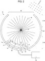
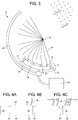
- Fig. 1 depicts an embodiment of an atomization device 10 as provided by the present disclosure, wherein the device 10 includes a contact plate 12, a liquid source 26, and a brush 28.
- the contact plate 12 includes a top plate 14 and a bottom plate 16.
- the top plate 14 and bottom plate 16 are connected such that a connector 17 encloses a space 18 between the top plate 14 and bottom plate 16.
- the top plate 14 may be connected to the bottom plate 16 by any suitable connector 17, as shown in Figs. 1-3 .
- the connector 17 may include, but not limited to, a wall, screw, nail, bolt, latch, among others. Further, the connector 17 may be any suitable material, such as plastic.
- the top plate 14 and bottom plate 14 may be directly connected to each other, for example, by welding, glue, or any suitable adhesive.
- the top plate 14 includes a plurality of capillary openings 20 that extend through the top plate 14 from a top surface 22 to a bottom surface 24.
- the capillary openings 20 are adapted to absorb liquid from the space 18 below the top plate 14 based on capillary action, and to present extremely small amounts of the liquid to adhere to the heads of the filaments 30 when they contact the tops of the openings.
- the diameter of the capillary openings 20 may be increased or decreased to suit liquids of different viscosity, or to modify a projected droplet size.
- the capillary openings 20 may be arranged in any suitable manner that ensures the filaments 30 which are to atomize in the desired process have access to the liquid within the capillary openings 20.
- the capillary openings 20 may be arranged in a staggered grid pattern.
- the diameter of the capillary openings 20 may be any suitable diameter to produce atomization of the liquid.
- the diameter of the capillary openings 20 may be at least 0.1 mm, at least 0.3 mm, at least 0.5 mm, at least 0.7 mm, at least 0.9 mm, or at least 1.1 mm.
- the diameter of the capillary openings 20 may be less than 3 mm, less than 2 mm, less than 1.5 mm, less than 1.3 mm, less than 1.1 mm, less than 0.9 mm, less than 0.7 mm, or less than 0.5 mm.
- the diameter of the capillary openings 20 may be defined by any two of the above endpoints.
- the diameter of the capillary openings 20 may be between, and including, 0.5 mm to 1.5 mm, 0.9 mm to 1.1 mm, 0.7 mm to 1.3 mm, or 0.9 mm to 1.3 mm. In an example, the diameter of the capillary openings 20 is 1 mm.
- the space between the top plate 14 and the bottom plate 16 may be approximately from 0.5 mm to 2 mm, for example 1 mm. Due to the close proximity of the top plate 14 and bottom plate 16 in addition to the interplay of capillary action in the case of a liquid with the viscosity of water, the device 10 may be used in any orientation. In other words, the contact plate 12 adequately supplies liquid through the capillary openings 20 to the filaments 30 in any orientation of the device, including upright or upside down.
- a portion of the contact plate 12 includes a spirally curved surface with which the filaments 30 contact.
- the radius of the spirally curved surface decreases along a path following the first radial direction.
- a filament 30 of the brush is progressively more intensely flexed as the filament 30 approaches the end of the spirally curved surface.
- top plate 14 including a spiral curved surface includes preventing the accumulation of liquid behind a strike plate, an element common in conventional sprayers that is used to snap bristles to release their droplets. Any liquid that accumulates behind a strike plate is typically attached to subsequent approaching bristles, and will drastically increase the projected drop size and negatively impair atomization.
- the spiral curved surface of the top plate 14 maintains an optimal amount of liquid on the filaments 30 and prevents liquid from accumulating on the top surface 22 of the top plate 14 and subsequently absorbed by filaments 30, which negatively impairs atomization.
- the device 10 further includes a liquid source 26 in fluid communication with the space 18, wherein the liquid source 26 supplies a liquid to the space 18, wherein the plurality of capillary openings 20 access the liquid from the space 18.
- the liquid source may attach to the bottom plate 16, for example through an opening within the bottom plate 16, wherein the liquid may flow from the liquid source 26 into the space 18.
- the liquid source 26 may supply any suitable liquid to the space 18.
- the liquid source 26 may control the release of liquid to maintain an amount of liquid in the space 18 such that the liquid does not overflow the capillary openings 20 and onto the top surface 22 of the top plate 14.
- the liquid source 26 includes a positive pressure source, wherein the positive pressure maintains an amount of liquid between the top plate 14 and bottom plate 16.
- the liquid source 26 may be externally located from the contact plate 12. Alternatively, or in addition to, the liquid source 26 may be internally located within a housing 34, discussed more below. Further, the liquid source 20 may be in fluid communication with a liquid reservoir that supplies the liquid source 20 with liquid.
- the device 10 will not produce a consistent mist of liquid, but rather dispense inconsistent droplets of too large a size.
- the device 10 may not produce a consistent mist of liquid, but instead have gaps in its spray.
- the liquid source controls the release of liquid to maintain an amount of liquid in the capillary openings less than a full capacity of the capillary openings.
- the liquid supplied by the liquid source 20 may be any suitable type of liquid including, but not limited to, water, paint, insecticide, air freshener, fuel, pharmaceutical coatings, industrial coatings, industrial oil, cooking oil, body creams, combustible liquid or petroleum derivatives, or a combination thereof.
- the misting device 10 is generally configured to perform with paint, which is a fluid that has shear thinning properties (i.e., the fluid's resistance to flow decreases with an increasing rate of shear stress).
- paint which is a fluid that has shear thinning properties (i.e., the fluid's resistance to flow decreases with an increasing rate of shear stress).
- shear thinning properties i.e., the fluid's resistance to flow decreases with an increasing rate of shear stress
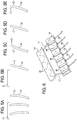
- the device 10 also includes a brush 28 including a plurality of a filaments 30 radiating from a central axis 32 of the rotating brush 28.
- a brush 28 including a plurality of a filaments 30 radiating from a central axis 32 of the rotating brush 28.
- the brush 28 rotates a first radial direction with the filament heads in contact with the plate, liquid adheres to the filament heads from within the capillary openings, the filaments 30 flex when in contact with the contact plate 12 and release when contact is broken with the contact plate 12 to project liquid from the filaments 30.
- the oscillation process begins, which will atomize the liquid on the filaments, one drop with each oscillation.
- the brush 28 may be linear, wherein the filaments 30 extend from one side of the brush 28. In such example, instead of rotating the brush, a horizontal brush 28 may slide or vibrate over the contact plate 12.
- the filaments 30 may be comprised of various materials with a range of flexibilities.
- the filaments 30 may comprise flexible material.
- the level of flexibility of the filaments 30 must be such that, upon contact with the contact plate 12, the filaments 30 bend or flex from their original orientation. Upon release from the contact barrier 12, the filaments 30 oscillate rapidly until the filaments 30 return back to their original, linear orientation, thereby releasing liquid from the filaments 30 in each oscillation.
- the filaments 30 upon release, typically not only spring back into their original orientation, but continue to bend past their original orientation into a forward bend position and then back to their linear position.
- the filaments 30 may then bend back to a backwards bend position, after which the filament 30 returns back to the linear position.
- This oscillation from the forward bend position to the backwards bend position creates the mist or atomization as the liquid leaves the filaments 30 each time the filament 30 oscillates away from the forward or the backward bend position.
- the filaments 30 are flexible enough to bend and spring back to their original orientation to allow the liquid on the filaments 30 to be projected in the form of a mist. In an example with a filament 30 having a length of one inch, the filament 30 may oscillate approximately 20 times before returning to its neutral, linear position.
- the filaments 30 may be equally dispersed on the rotating brush 28. Alternatively, the filaments 30 may be arranged in any number of patterns, such as rows, along the rotating brush.
- the projected droplet size can also be moderated by changing the distribution of filaments 30 across the face or the surface of the central axis 32 of the brush 28. The more spread out the filaments 30 are on a surface of the central axis 32, the more discreet individual droplets are projected. Further, the filaments 30 may extend perpendicular from a surface of the brush 28.
- the filaments 30 may extend at an angle other than perpendicular, such as sloping backwards from the direction of rotation so as to project droplets in a direction closer to a line pointing outwards from the center of the brush (in contrast to a tangential line of droplets projected by filaments 30 extending perpendicular from the brush 28).
- the length of the filaments 30 may be any suitable length to produce atomization of the liquid.
- the length of the filament 30 may be at least 10 mm, at least 15 mm, at least 20 mm, at least 25 mm, at least 30 mm, at least 35 mm, or at least 40 mm.
- the length of the filaments 30 may be less than 50 mm, less than 45 mm, less than 40 mm, less than 35 mm, less than 30 mm, less than 25 mm, or less than 20 mm.
- the filaments have a length defined by any two of the above endpoints.
- the length of the filaments 30 may be between, and including, 15 mm to 50 mm, 25 mm to 30 mm, 20 mm to 40 mm, or 25 mm to 35 mm.
- the rotating brush 28 is replaceable.
- the user may replace the rotating brush 28 with a different rotating brush 28 that has, for example, a different density of filaments 30 or a brush that has a different pattern of filaments 30, thereby allowing the user to create various misting conditions and patterns.
- the rotating brush 28 may be driven by an electrical motor 44.
- the rotating brush 28 may be driven by a manual crank, such as a thumb roller. In either case, a user may be able to designate or otherwise control the speed of rotation of the brush 28.
- the device 10 is configured to convert 500 mL to 800 mL of liquid into a mist per hour.
- the device may be configured to convert 600 mL of liquid into mist per hour.
- the device 10 includes a housing 34.
- the housing 34 is generally cylindrical.
- the size and shape of the housing 34 is not limiting.
- Fig. 2 shows a generally cylindrical housing 34, it is understood that the housing may be any number of shapes adapted to support the misting device 10.
- the housing 34 may include the contact plate 12 and the rotating brush 28.
- the housing 34 may include an opening 36, wherein, as the brush 28 rotates, liquid from the filaments 30 project through the opening 36.
- the housing 34 may include a top portion 38 and a bottom portion 40, wherein the contact plate 12 is positioned within the bottom portion 40, wherein the opening 36 is positioned within the top portion 38.
- the shape of the opening 36 may be any suitable shape.
- the shape of the opening 36 may be generally rectangular, square, circular, or oblong.
- the opening 36 may be a narrow slit, a small circular opening, or a larger rectangular opening.
- the housing 34 may include more than one opening 36, thus, allowing the device 10 to provide various patterns of misting.
- the top portion 38 of the housing 34 may include a row or series of small openings 36.
- the size of the opening 36 in the top portion 38 of the housing 34 may be adjustable.
- the opening 36 can be enlarged or diminished manually or electronically.
- the opening 36 may have adjustable components that allow a user to change the shape of the opening, even during use.
- the capillary openings 20 may be capable of being opened and closed in certain groups, allowing for a customized liquid spray swath.
- the device 10 includes an arcuate barrier 42 extending from below the contact plate 12 around a portion of the brush 28, wherein the arcuate barrier 42 may collect a portion of a liquid released from the filaments 30.
- the barrier may be a portion of the housing 34.
- the barrier 42 may be in addition to the housing 34.
- the barrier 42 extends from below the contact plate 12 to approximately 90 degrees from the contact plate 12, wherein the approximate 90 degrees is measured along the radial path of the filaments 30.
- the barrier 42 may collect any liquid prematurely released at or less than 90 degrees.
- the barrier 42 may in fluid communication with the liquid source 26, such that the collected liquid may be fed back into the liquid source 26.
- a portion of the liquid carried by the filaments 30 is released from the filaments approximately 180 degrees from the contact plate 12 in the form of a mist, wherein the approximately 180 degrees is measured along the radial path of the rotating brush 28. Because atomization does not take place until the filaments 30 oscillate, and the oscillation only starts after the filaments 30 have rotated approximately 90 degrees, the direction of the sprayed droplets is 180 degrees from the contact plate 12. In contrast to conventional sprayers that sling liquid approximately 90 degrees from a snap plate without any oscillation process, the present device projects mist at approximately 180 degrees from the contact plate 12.
- the device 10 may be configured to produce atomized particles of any suitable size or shape.
- the rotation rate of the rotating brush 28 may be slowed down, the amount of liquid supplied to the filaments 30 may be increased, the diameter of the capillary holes may be increased, the thickness of the filaments 30 may be increased, the stiffness of the filaments 30 may be decreased, or combination thereof.
- the rotation rate of the rotating brush 28 may be increased, the amount of liquid supplied to the filaments 30 may be decreased, the diameter of the capillary holes may be decreased, the thickness of the filaments 30 may be decreased, the stiffness of the filaments 30 may be increased, or a combination thereof.
- the shape of the particles may be spherical, ovular, torpedo-shaped, cylindrical and bullet-shaped.
- the device 10 may be configured to spray the liquid particles varying distances, for example, the stiffness of the filaments 30 may be increased to spray the particles longer distances compared to filaments 30 with decreased stiffness.
- the device may atomize liquid so rapidly that it produces immediate evaporation of liquid into gas, skipping entirely the intermediary step of creation of small particles.
- the liquid particles may have an average size (i.e., average particle diameter) of at least 10 ⁇ m, at least 20 ⁇ m, at least 30 ⁇ m, at least 40 ⁇ m, or at least 60 ⁇ m.
- the liquid particles may have a diameter size of 350 ⁇ m or less, 300 ⁇ m or less, 200 ⁇ m or less, 180 ⁇ m or less, 160 ⁇ m or less, 150 ⁇ m or less, 120 ⁇ m, 100 ⁇ m or less, 50 ⁇ m or less, or 20 ⁇ m or less.
- the liquid particles can have an average particle size bounded by any two of the above endpoints.
- the liquid particles may have an average particle size of 10 ⁇ m to 20 ⁇ m, 10 ⁇ m to 50 ⁇ m, 10 ⁇ m to 200 ⁇ m, 20 ⁇ m to 100 ⁇ m, 20 ⁇ m to 3500 ⁇ ,m 50 ⁇ m to 120 ⁇ m, 20 ⁇ m to 150 ⁇ m, or 60 ⁇ m to 100 ⁇ m.
- the device 10 is enabled to dispense liquid from the filaments 30, wherein the liquid may be projected in the form of droplets, wherein at least 50% of the droplets have a diameter size of 100 microns or less.
- the device 10 is configured to produce approximately 7 droplets of average diameter size of 115 microns per complete oscillation cycle of each filament, converting approximately 0.25 mL of liquid into mist per hour per filament 30, when the filament 30 passes through approximately 800 cycles of liquid adhesion and oscillation of mist per minute.
- the present disclosure also provides an atomization method including providing any of the embodiments of the atomization device 10 disclosed above.
- the method further includes rotating the brush 28 such that the filaments 30 contact the contact plate 12, wherein the filaments 30 absorb a portion of the liquid available to the filaments 30 from within the capillary openings 20.
- a filament 30 brushes over the top plate 14 of the contact plate 14 and absorbs liquid from the capillary opening 20 even though no external source is forcing any additional liquid through the capillary opening 20.
- the filaments 30 flex when in contact with the contact plate 12 and release when contact is broken with the contact plate 12 to project liquid from the filaments 30.
- the filaments 30 return to a neutral (linear) position, then continue to bend in the opposite direction of the flexing from the contact plate 12. Then the filaments 30 return back to the neutral position again, and then bend backwards past neutral, releasing one drop with each change in direction.
- the particular oscillation cycle of the filaments 30 to bend beyond the neutral or linear position of the filament 30, creates the claimed atomization.
- bristles of conventional sprayers may be merely bent back and then snapped forward to return to their linear position, applying a flicking motion instead of the oscillating motion utilized by the present device.
- a 0.3 mm (0.012") nylon filament 30 that is 25.4 mm (1") long produces 22 cycles of oscillation, or about 44 recoils.
- a filament 0.3 mm (0.012") in diameter 25.4 mm (1") long can cast a stream of individual droplets separated by identical intervals of time in the range of 22 droplets per 1 ⁇ 4 second in one direction.
- the device 10 utilizes approximately the first 15% of the oscillations when operated at 600 rpm. With each oscillation, the filament projects one droplet of liquid adhering to the end of the filament 30 in the forward direction of rotation, and another in the backward direction.
- the acceleration at the point of reversal of direction is comparable to the power concentrated at the atomizing point of a spinning disc atomization system rotating at 3,500 rpm.
- Fig. 6 depicts an embodiment of the contact plate 12, wherein the bottom plate 16 includes stays 46 that extend vertically from a top surface of the bottom plate 16 to the bottom surface 24 of the top plate 14.
- the bottom plate 16 may include multiple liquid sources 26, such that liquid is fed into the individual spaces 18 between the stays 46.
- a liquid source 26 is adapted to supply liquid to a portion of capillary stays between stays 46.
- Such example is particularly suitable for atomizing more viscous liquids such as paint that are not suitable to the capillary plate design used for water, which can already be used in any orientation.
- the stays 46 allow the device to be used in various orientations. In other words, the device 10 may be tilted during use while still maintaining adequate misting ability. Without the incorporation of the stays 46, when the device is tilted, all of the liquid in the space 18 may accumulate in one end of the space 18. As a result, only the capillary openings 20 at the end where the liquid is accumulated will absorb the liquid, thereby altering the availability of the liquid to the filaments 30. In contrast, with the incorporation of the stays 46 between the top plate 14 and the bottom plate 16, the device 10 may be tilted without the liquid accumulating at one end of the space 18. Instead, the stays 46 ensure an adequate amount of liquid is accessible by all of the plurality of capillary openings 20 regardless of the orientation of the device 10.
- the device 10 may further include an overflow mechanism configured to maintain an adequate amount of liquid in the liquid source 20 in order for the device 10 to produce a consistent mist of liquid.
- the overflow mechanism may be any mechanical or electrical device configured to maintain a specific amount of liquid in the liquid source 26.
- the overflow mechanism may be in communication with liquid source 26, such that upon feedback from the liquid source 26 that the amount of liquid exceeds the optimal amount for the device 10 to produce a continuous mist, the overflow mechanism stores or directs excess liquid to a liquid reservoir.
- the overflow mechanism may be in communication with the space 18, such that upon feedback from the space 18 that the amount of liquid exceeds the optimal amount for the device 10 to produce adequate atomization, the overflow mechanism stores or directs excess liquid to the liquid source 26.
- the device 10 may include a float valve configured to maintain a certain amount of liquid in the space 18.
- the predetermined level or height of the liquid in the space 18 may be made adjustable using an adjustment knob.
- the device 10 may further comprise an air force mechanism that provides air flow that further aids in mist production.
- the air force mechanism may be any mechanism that provides air flow, for example, although not limited to, a fan.
- the air flow may flow along the length of the rotating brush 28.
- the air force mechanism may provide air flow that is tangential to the rotation of the rotating brush 28.
- the air force mechanism may provide air in the direction of the opening 36 in the housing 34, thereby aiding the release of liquid from the filaments 30.
- the air force mechanism may also provide a cooling effect, for example, when the liquid is water.
Landscapes
- Nozzles (AREA)
- Application Of Or Painting With Fluid Materials (AREA)
Applications Claiming Priority (3)
| Application Number | Priority Date | Filing Date | Title |
|---|---|---|---|
| US201361835529P | 2013-06-14 | 2013-06-14 | |
| US14/301,466 US9339837B2 (en) | 2013-06-14 | 2014-06-11 | Misting and atomization systems and methods |
| PCT/US2015/034809 WO2015191516A1 (en) | 2013-06-14 | 2015-06-09 | Misting and atomization systems and methods |
Publications (3)
| Publication Number | Publication Date |
|---|---|
| EP3154706A1 EP3154706A1 (en) | 2017-04-19 |
| EP3154706A4 EP3154706A4 (en) | 2017-09-20 |
| EP3154706B1 true EP3154706B1 (en) | 2021-01-13 |
Family
ID=52018387
Family Applications (1)
| Application Number | Title | Priority Date | Filing Date |
|---|---|---|---|
| EP15806888.2A Active EP3154706B1 (en) | 2013-06-14 | 2015-06-09 | Misting and atomization systems and methods |
Country Status (5)
| Country | Link |
|---|---|
| US (1) | US9339837B2 (enExample) |
| EP (1) | EP3154706B1 (enExample) |
| JP (1) | JP6670255B2 (enExample) |
| CA (1) | CA2951380C (enExample) |
| WO (1) | WO2015191516A1 (enExample) |
Families Citing this family (4)
| Publication number | Priority date | Publication date | Assignee | Title |
|---|---|---|---|---|
| US9869517B2 (en) * | 2013-06-14 | 2018-01-16 | Snapp Ip Ltd | Misting and atomization systems and method |
| KR101968972B1 (ko) * | 2016-02-05 | 2019-04-15 | 주식회사 코드스테리 | 활성화된 살균액 발생 장치 및 방법 |
| US20190374961A1 (en) * | 2018-04-19 | 2019-12-12 | Gary Stephen Moore | Spinner Base Mosquito Misting Device |
| WO2020082063A1 (en) * | 2018-10-19 | 2020-04-23 | The Fountainhead Group, Inc. | Fluid dispensing device and pump |
Family Cites Families (24)
| Publication number | Priority date | Publication date | Assignee | Title |
|---|---|---|---|---|
| US629513A (en) | 1898-11-30 | 1899-07-25 | Ernst Liebscher | Spraying device for paints. |
| US2199093A (en) | 1937-12-22 | 1940-04-30 | Harry C Wolfenden | Dye spattering machine |
| US2250340A (en) | 1941-01-14 | 1941-07-22 | Harry C Wolfenden | Dye-spattering machine |
| US2368742A (en) | 1941-06-25 | 1945-02-06 | Lock Joint Pipe Co | Apparatus for applying plastic coatings |
| US2730738A (en) | 1953-05-29 | 1956-01-17 | Humes Donald Thomas | Power driven applicator for liquid materials |
| US2865325A (en) | 1954-11-01 | 1958-12-23 | Theodore I Leston | Applicator for spattering masses |
| US2763510A (en) | 1954-12-09 | 1956-09-18 | Nicola Joseph Di | Paint drop flinger |
| US2876039A (en) | 1955-07-22 | 1959-03-03 | Bahlsen Werner | Apparatus for distributing pasty material |
| US2986337A (en) | 1959-12-22 | 1961-05-30 | Clare Maurice Ch | Moistening device for offset printing machines and the like |
| DE7613874U1 (de) | 1976-05-03 | 1976-09-30 | Grundig E.M.V. Elektro-Mechanische Versuchsanstalt Max Grundig, 8510 Fuerth | Vorrichtung zum auftragen von fluxmittel auf leiterplatten |
| DE2814681A1 (de) | 1978-04-05 | 1979-10-18 | Hauni Werke Koerber & Co Kg | Verfahren und vorrichtung zum auftragen von weichmacher auf eine bewegte gewebebahn |
| US5314119A (en) * | 1992-04-20 | 1994-05-24 | Latanick Equipment, Inc. | Method and apparatus for applying thin coatings of fluid droplets |
| US5842642A (en) | 1996-06-21 | 1998-12-01 | Plasko; Phil | Method and apparatus for spattering masses |
| DE19830801C2 (de) * | 1998-07-09 | 2001-05-10 | Anton Jaeger | Vorrichtung zum Ausstoßen von Flüssigkeit |
| ATE260143T1 (de) | 1999-11-26 | 2004-03-15 | Johnson Diversey Inc | Applikator zum auftragen eines fluids auf eine oberfläche und verfahren zum auftragen eines fluids auf eine oberfläche |
| DE20022545U1 (de) * | 2000-09-22 | 2001-12-06 | Alfred Kärcher GmbH & Co., 71364 Winnenden | Rotordüse, insbesondere für ein Hochdruckreinigungsgerät |
| TW505727B (en) | 2001-03-02 | 2002-10-11 | James Hardide Res Pty Ltd | A method and apparatus for forming a laminated sheet material by spattering |
| US6896200B2 (en) | 2001-12-31 | 2005-05-24 | David O. Dobson | Hand-held applicator device for applying a layer of fluid droplets |
| US7721976B2 (en) * | 2002-07-22 | 2010-05-25 | Durr Systems, Inc. | High speed rotating atomizer assembly |
| US7429297B1 (en) | 2004-03-31 | 2008-09-30 | Chandler Dennis J | Applicator for texturing |
| EP2236055A1 (en) * | 2009-04-04 | 2010-10-06 | Braun GmbH | Body groomimg device comprising an atomizer unit |
| US8327787B2 (en) * | 2009-05-29 | 2012-12-11 | Seward Marine Services Inc. | Rotating spray head and system for induced suction generation |
| JP2013169500A (ja) * | 2012-02-20 | 2013-09-02 | Ricoh Co Ltd | スピンカップ洗浄方法 |
| US8960568B2 (en) * | 2013-03-11 | 2015-02-24 | Wen-Pin Chen | Brush wheel typed nebulizer |
-
2014
- 2014-06-11 US US14/301,466 patent/US9339837B2/en active Active
-
2015
- 2015-06-09 CA CA2951380A patent/CA2951380C/en active Active
- 2015-06-09 EP EP15806888.2A patent/EP3154706B1/en active Active
- 2015-06-09 JP JP2016570239A patent/JP6670255B2/ja active Active
- 2015-06-09 WO PCT/US2015/034809 patent/WO2015191516A1/en not_active Ceased
Non-Patent Citations (1)
| Title |
|---|
| None * |
Also Published As
| Publication number | Publication date |
|---|---|
| WO2015191516A1 (en) | 2015-12-17 |
| US9339837B2 (en) | 2016-05-17 |
| CA2951380A1 (en) | 2015-12-17 |
| EP3154706A1 (en) | 2017-04-19 |
| EP3154706A4 (en) | 2017-09-20 |
| CA2951380C (en) | 2022-06-14 |
| JP6670255B2 (ja) | 2020-03-18 |
| US20140367492A1 (en) | 2014-12-18 |
| JP2017520392A (ja) | 2017-07-27 |
Similar Documents
| Publication | Publication Date | Title |
|---|---|---|
| JP7212011B2 (ja) | マイクロ流体送達カートリッジ、及びカートリッジをマイクロ流体送達システムと接続する方法 | |
| JP6921981B2 (ja) | マイクロ流体送達装置と共に使用するためのマイクロ流体送達カートリッジ | |
| EP3154706B1 (en) | Misting and atomization systems and methods | |
| JP6666434B2 (ja) | マイクロ流体送達システム、及び外側カバーを有するカートリッジ | |
| JP2018537263A (ja) | マイクロ流体送達システム、及び外側カバーを有するカートリッジ | |
| BR112020019992B1 (pt) | Malha para um conjunto atomizador, conjunto atomizador para um dispositivo gerador de aerossol e dispositivo gerador de aerossol | |
| JP6928666B2 (ja) | 流体組成物を空気中に上方向に向けて分注するためのマイクロ流体送達装置及び方法 | |
| US20180297052A1 (en) | Methods and systems for creating aerosols | |
| US9869517B2 (en) | Misting and atomization systems and method | |
| US3648935A (en) | Spray apparatus with movable head | |
| CN101909766A (zh) | 涂漆装置 | |
| KR20170018354A (ko) | 분무 및 분무화 시스템 및 방법 | |
| JP2011194304A (ja) | 接着剤塗布装置 | |
| NZ204015A (en) | Liquid sprayer with rotary atomiser | |
| HK1237302A1 (zh) | 喷雾和雾化系统和方法 | |
| US5246167A (en) | Droplet application device and method | |
| US3070263A (en) | Dispensing device for micro-pulverized material | |
| CN102149478A (zh) | 具有泡沫金属插入件的旋转喷雾器 | |
| CN100518956C (zh) | 微雾滴产生装置 | |
| JP5433896B2 (ja) | ポンプ式噴霧装置 | |
| GB2164872A (en) | Centrifugal spray | |
| CN210646905U (zh) | 一种药液回收式离心喷头 | |
| US20210362172A1 (en) | Fluid dispensing device and pump | |
| WO2014160704A1 (en) | Fluid dispenser and method of forming fluid dispenser | |
| JP4346418B2 (ja) | 塗布機用補助具 |
Legal Events
| Date | Code | Title | Description |
|---|---|---|---|
| STAA | Information on the status of an ep patent application or granted ep patent |
Free format text: STATUS: THE INTERNATIONAL PUBLICATION HAS BEEN MADE |
|
| PUAI | Public reference made under article 153(3) epc to a published international application that has entered the european phase |
Free format text: ORIGINAL CODE: 0009012 |
|
| STAA | Information on the status of an ep patent application or granted ep patent |
Free format text: STATUS: REQUEST FOR EXAMINATION WAS MADE |
|
| 17P | Request for examination filed |
Effective date: 20170111 |
|
| AK | Designated contracting states |
Kind code of ref document: A1 Designated state(s): AL AT BE BG CH CY CZ DE DK EE ES FI FR GB GR HR HU IE IS IT LI LT LU LV MC MK MT NL NO PL PT RO RS SE SI SK SM TR |
|
| AX | Request for extension of the european patent |
Extension state: BA ME |
|
| A4 | Supplementary search report drawn up and despatched |
Effective date: 20170822 |
|
| DAV | Request for validation of the european patent (deleted) | ||
| DAX | Request for extension of the european patent (deleted) | ||
| RIC1 | Information provided on ipc code assigned before grant |
Ipc: B05B 3/02 20060101AFI20170816BHEP Ipc: B05B 7/24 20060101ALI20170816BHEP |
|
| STAA | Information on the status of an ep patent application or granted ep patent |
Free format text: STATUS: EXAMINATION IS IN PROGRESS |
|
| 17Q | First examination report despatched |
Effective date: 20180706 |
|
| GRAP | Despatch of communication of intention to grant a patent |
Free format text: ORIGINAL CODE: EPIDOSNIGR1 |
|
| STAA | Information on the status of an ep patent application or granted ep patent |
Free format text: STATUS: GRANT OF PATENT IS INTENDED |
|
| INTG | Intention to grant announced |
Effective date: 20200408 |
|
| GRAS | Grant fee paid |
Free format text: ORIGINAL CODE: EPIDOSNIGR3 |
|
| GRAA | (expected) grant |
Free format text: ORIGINAL CODE: 0009210 |
|
| STAA | Information on the status of an ep patent application or granted ep patent |
Free format text: STATUS: THE PATENT HAS BEEN GRANTED |
|
| AK | Designated contracting states |
Kind code of ref document: B1 Designated state(s): AL AT BE BG CH CY CZ DE DK EE ES FI FR GB GR HR HU IE IS IT LI LT LU LV MC MK MT NL NO PL PT RO RS SE SI SK SM TR |
|
| REG | Reference to a national code |
Ref country code: GB Ref legal event code: FG4D |
|
| REG | Reference to a national code |
Ref country code: CH Ref legal event code: EP |
|
| REG | Reference to a national code |
Ref country code: IE Ref legal event code: FG4D |
|
| REG | Reference to a national code |
Ref country code: DE Ref legal event code: R096 Ref document number: 602015064790 Country of ref document: DE |
|
| REG | Reference to a national code |
Ref country code: AT Ref legal event code: REF Ref document number: 1354157 Country of ref document: AT Kind code of ref document: T Effective date: 20210215 |
|
| REG | Reference to a national code |
Ref country code: CH Ref legal event code: NV Representative=s name: NOVAGRAAF INTERNATIONAL SA, CH |
|
| REG | Reference to a national code |
Ref country code: NL Ref legal event code: FP |
|
| REG | Reference to a national code |
Ref country code: AT Ref legal event code: MK05 Ref document number: 1354157 Country of ref document: AT Kind code of ref document: T Effective date: 20210113 |
|
| REG | Reference to a national code |
Ref country code: LT Ref legal event code: MG9D |
|
| PG25 | Lapsed in a contracting state [announced via postgrant information from national office to epo] |
Ref country code: BG Free format text: LAPSE BECAUSE OF FAILURE TO SUBMIT A TRANSLATION OF THE DESCRIPTION OR TO PAY THE FEE WITHIN THE PRESCRIBED TIME-LIMIT Effective date: 20210413 Ref country code: HR Free format text: LAPSE BECAUSE OF FAILURE TO SUBMIT A TRANSLATION OF THE DESCRIPTION OR TO PAY THE FEE WITHIN THE PRESCRIBED TIME-LIMIT Effective date: 20210113 Ref country code: FI Free format text: LAPSE BECAUSE OF FAILURE TO SUBMIT A TRANSLATION OF THE DESCRIPTION OR TO PAY THE FEE WITHIN THE PRESCRIBED TIME-LIMIT Effective date: 20210113 Ref country code: GR Free format text: LAPSE BECAUSE OF FAILURE TO SUBMIT A TRANSLATION OF THE DESCRIPTION OR TO PAY THE FEE WITHIN THE PRESCRIBED TIME-LIMIT Effective date: 20210414 Ref country code: NO Free format text: LAPSE BECAUSE OF FAILURE TO SUBMIT A TRANSLATION OF THE DESCRIPTION OR TO PAY THE FEE WITHIN THE PRESCRIBED TIME-LIMIT Effective date: 20210413 Ref country code: PT Free format text: LAPSE BECAUSE OF FAILURE TO SUBMIT A TRANSLATION OF THE DESCRIPTION OR TO PAY THE FEE WITHIN THE PRESCRIBED TIME-LIMIT Effective date: 20210513 Ref country code: LT Free format text: LAPSE BECAUSE OF FAILURE TO SUBMIT A TRANSLATION OF THE DESCRIPTION OR TO PAY THE FEE WITHIN THE PRESCRIBED TIME-LIMIT Effective date: 20210113 |
|
| PG25 | Lapsed in a contracting state [announced via postgrant information from national office to epo] |
Ref country code: SE Free format text: LAPSE BECAUSE OF FAILURE TO SUBMIT A TRANSLATION OF THE DESCRIPTION OR TO PAY THE FEE WITHIN THE PRESCRIBED TIME-LIMIT Effective date: 20210113 Ref country code: AT Free format text: LAPSE BECAUSE OF FAILURE TO SUBMIT A TRANSLATION OF THE DESCRIPTION OR TO PAY THE FEE WITHIN THE PRESCRIBED TIME-LIMIT Effective date: 20210113 Ref country code: RS Free format text: LAPSE BECAUSE OF FAILURE TO SUBMIT A TRANSLATION OF THE DESCRIPTION OR TO PAY THE FEE WITHIN THE PRESCRIBED TIME-LIMIT Effective date: 20210113 Ref country code: PL Free format text: LAPSE BECAUSE OF FAILURE TO SUBMIT A TRANSLATION OF THE DESCRIPTION OR TO PAY THE FEE WITHIN THE PRESCRIBED TIME-LIMIT Effective date: 20210113 Ref country code: LV Free format text: LAPSE BECAUSE OF FAILURE TO SUBMIT A TRANSLATION OF THE DESCRIPTION OR TO PAY THE FEE WITHIN THE PRESCRIBED TIME-LIMIT Effective date: 20210113 |
|
| PG25 | Lapsed in a contracting state [announced via postgrant information from national office to epo] |
Ref country code: IS Free format text: LAPSE BECAUSE OF FAILURE TO SUBMIT A TRANSLATION OF THE DESCRIPTION OR TO PAY THE FEE WITHIN THE PRESCRIBED TIME-LIMIT Effective date: 20210513 |
|
| REG | Reference to a national code |
Ref country code: DE Ref legal event code: R097 Ref document number: 602015064790 Country of ref document: DE |
|
| PG25 | Lapsed in a contracting state [announced via postgrant information from national office to epo] |
Ref country code: EE Free format text: LAPSE BECAUSE OF FAILURE TO SUBMIT A TRANSLATION OF THE DESCRIPTION OR TO PAY THE FEE WITHIN THE PRESCRIBED TIME-LIMIT Effective date: 20210113 Ref country code: CZ Free format text: LAPSE BECAUSE OF FAILURE TO SUBMIT A TRANSLATION OF THE DESCRIPTION OR TO PAY THE FEE WITHIN THE PRESCRIBED TIME-LIMIT Effective date: 20210113 Ref country code: SM Free format text: LAPSE BECAUSE OF FAILURE TO SUBMIT A TRANSLATION OF THE DESCRIPTION OR TO PAY THE FEE WITHIN THE PRESCRIBED TIME-LIMIT Effective date: 20210113 |
|
| PLBE | No opposition filed within time limit |
Free format text: ORIGINAL CODE: 0009261 |
|
| STAA | Information on the status of an ep patent application or granted ep patent |
Free format text: STATUS: NO OPPOSITION FILED WITHIN TIME LIMIT |
|
| PG25 | Lapsed in a contracting state [announced via postgrant information from national office to epo] |
Ref country code: ES Free format text: LAPSE BECAUSE OF FAILURE TO SUBMIT A TRANSLATION OF THE DESCRIPTION OR TO PAY THE FEE WITHIN THE PRESCRIBED TIME-LIMIT Effective date: 20210113 Ref country code: DK Free format text: LAPSE BECAUSE OF FAILURE TO SUBMIT A TRANSLATION OF THE DESCRIPTION OR TO PAY THE FEE WITHIN THE PRESCRIBED TIME-LIMIT Effective date: 20210113 Ref country code: SK Free format text: LAPSE BECAUSE OF FAILURE TO SUBMIT A TRANSLATION OF THE DESCRIPTION OR TO PAY THE FEE WITHIN THE PRESCRIBED TIME-LIMIT Effective date: 20210113 Ref country code: RO Free format text: LAPSE BECAUSE OF FAILURE TO SUBMIT A TRANSLATION OF THE DESCRIPTION OR TO PAY THE FEE WITHIN THE PRESCRIBED TIME-LIMIT Effective date: 20210113 |
|
| 26N | No opposition filed |
Effective date: 20211014 |
|
| PG25 | Lapsed in a contracting state [announced via postgrant information from national office to epo] |
Ref country code: AL Free format text: LAPSE BECAUSE OF FAILURE TO SUBMIT A TRANSLATION OF THE DESCRIPTION OR TO PAY THE FEE WITHIN THE PRESCRIBED TIME-LIMIT Effective date: 20210113 Ref country code: MC Free format text: LAPSE BECAUSE OF FAILURE TO SUBMIT A TRANSLATION OF THE DESCRIPTION OR TO PAY THE FEE WITHIN THE PRESCRIBED TIME-LIMIT Effective date: 20210113 |
|
| PG25 | Lapsed in a contracting state [announced via postgrant information from national office to epo] |
Ref country code: SI Free format text: LAPSE BECAUSE OF FAILURE TO SUBMIT A TRANSLATION OF THE DESCRIPTION OR TO PAY THE FEE WITHIN THE PRESCRIBED TIME-LIMIT Effective date: 20210113 |
|
| PG25 | Lapsed in a contracting state [announced via postgrant information from national office to epo] |
Ref country code: LU Free format text: LAPSE BECAUSE OF NON-PAYMENT OF DUE FEES Effective date: 20210609 |
|
| PG25 | Lapsed in a contracting state [announced via postgrant information from national office to epo] |
Ref country code: IT Free format text: LAPSE BECAUSE OF FAILURE TO SUBMIT A TRANSLATION OF THE DESCRIPTION OR TO PAY THE FEE WITHIN THE PRESCRIBED TIME-LIMIT Effective date: 20210113 |
|
| PG25 | Lapsed in a contracting state [announced via postgrant information from national office to epo] |
Ref country code: IS Free format text: LAPSE BECAUSE OF FAILURE TO SUBMIT A TRANSLATION OF THE DESCRIPTION OR TO PAY THE FEE WITHIN THE PRESCRIBED TIME-LIMIT Effective date: 20210513 |
|
| PG25 | Lapsed in a contracting state [announced via postgrant information from national office to epo] |
Ref country code: HU Free format text: LAPSE BECAUSE OF FAILURE TO SUBMIT A TRANSLATION OF THE DESCRIPTION OR TO PAY THE FEE WITHIN THE PRESCRIBED TIME-LIMIT; INVALID AB INITIO Effective date: 20150609 |
|
| PG25 | Lapsed in a contracting state [announced via postgrant information from national office to epo] |
Ref country code: CY Free format text: LAPSE BECAUSE OF FAILURE TO SUBMIT A TRANSLATION OF THE DESCRIPTION OR TO PAY THE FEE WITHIN THE PRESCRIBED TIME-LIMIT Effective date: 20210113 |
|
| PGFP | Annual fee paid to national office [announced via postgrant information from national office to epo] |
Ref country code: DE Payment date: 20230621 Year of fee payment: 9 |
|
| PG25 | Lapsed in a contracting state [announced via postgrant information from national office to epo] |
Ref country code: MK Free format text: LAPSE BECAUSE OF FAILURE TO SUBMIT A TRANSLATION OF THE DESCRIPTION OR TO PAY THE FEE WITHIN THE PRESCRIBED TIME-LIMIT Effective date: 20210113 |
|
| PG25 | Lapsed in a contracting state [announced via postgrant information from national office to epo] |
Ref country code: TR Free format text: LAPSE BECAUSE OF FAILURE TO SUBMIT A TRANSLATION OF THE DESCRIPTION OR TO PAY THE FEE WITHIN THE PRESCRIBED TIME-LIMIT Effective date: 20210113 |
|
| PGFP | Annual fee paid to national office [announced via postgrant information from national office to epo] |
Ref country code: IE Payment date: 20240618 Year of fee payment: 10 |
|
| PGFP | Annual fee paid to national office [announced via postgrant information from national office to epo] |
Ref country code: GB Payment date: 20240618 Year of fee payment: 10 |
|
| PGFP | Annual fee paid to national office [announced via postgrant information from national office to epo] |
Ref country code: NL Payment date: 20240617 Year of fee payment: 10 |
|
| PGFP | Annual fee paid to national office [announced via postgrant information from national office to epo] |
Ref country code: FR Payment date: 20240618 Year of fee payment: 10 |
|
| PGFP | Annual fee paid to national office [announced via postgrant information from national office to epo] |
Ref country code: BE Payment date: 20240617 Year of fee payment: 10 |
|
| PG25 | Lapsed in a contracting state [announced via postgrant information from national office to epo] |
Ref country code: MT Free format text: LAPSE BECAUSE OF FAILURE TO SUBMIT A TRANSLATION OF THE DESCRIPTION OR TO PAY THE FEE WITHIN THE PRESCRIBED TIME-LIMIT Effective date: 20210113 |
|
| PGFP | Annual fee paid to national office [announced via postgrant information from national office to epo] |
Ref country code: CH Payment date: 20240701 Year of fee payment: 10 |