EP3154397B1 - Device for ejecting a furniture part and piece of furniture - Google Patents
Device for ejecting a furniture part and piece of furniture Download PDFInfo
- Publication number
- EP3154397B1 EP3154397B1 EP15727418.4A EP15727418A EP3154397B1 EP 3154397 B1 EP3154397 B1 EP 3154397B1 EP 15727418 A EP15727418 A EP 15727418A EP 3154397 B1 EP3154397 B1 EP 3154397B1
- Authority
- EP
- European Patent Office
- Prior art keywords
- ejection lever
- ejection
- attachment section
- furniture
- section
- Prior art date
- Legal status (The legal status is an assumption and is not a legal conclusion. Google has not performed a legal analysis and makes no representation as to the accuracy of the status listed.)
- Active
Links
Images


Classifications
-
- A—HUMAN NECESSITIES
- A47—FURNITURE; DOMESTIC ARTICLES OR APPLIANCES; COFFEE MILLS; SPICE MILLS; SUCTION CLEANERS IN GENERAL
- A47B—TABLES; DESKS; OFFICE FURNITURE; CABINETS; DRAWERS; GENERAL DETAILS OF FURNITURE
- A47B88/00—Drawers for tables, cabinets or like furniture; Guides for drawers
- A47B88/40—Sliding drawers; Slides or guides therefor
- A47B88/453—Actuated drawers
- A47B88/457—Actuated drawers operated by electrically-powered actuation means
Definitions
- the WO 2011/130758 A1 relates to a pusher with a drivable ejection lever for ejecting a movable furniture part from a closed end position on a furniture body.
- From the DE 10 2009 030 668 A1 is a device with a drivable ejection lever for ejecting a movably received on a fixed furniture part furniture part known.
- Object of the present invention is to improve initially designated devices or furniture, so that a technically and economically advantageous use of the device is possible.
- an insert for differently shaped movable furniture parts should be possible flexibly with the provided device, an insert for differently shaped movable furniture parts.
- the invention relates to a device for ejecting a furniture part, which is movably received on a stationary furniture part, wherein the device is provided for attachment to one of the two furniture parts and comprises a mounted on the device and driven by a drive unit ejection lever, the an ejection operation from a start position on the device can be driven out, so that a contact portion on the ejection lever can be brought into contact with the other furniture part to eject the movably received furniture part in an opening direction relative to the stationary furniture part.
- the device is in particular tuned so that upon reaching the end of the ejection operation by the ejection lever, a contact between the abutment portion on the ejection lever and the other furniture part is repealed in particular under a further movement of the furniture part in the opening direction.
- the device may be mounted on the furniture body, wherein the ejection lever can be brought into contact with the abutment portion on the movable furniture part.
- the device is arranged on the movable furniture part and the contact section reaches the furniture body in contact, wherein the device on the movable furniture part, with an ejection process from the furniture body is repulsive, is moved.
- the ejection lever has a neck portion which is selectively removable along an existing separation area from the remaining part of the ejection lever, whereby a depth dimension of the ejection lever in the region of the abutment portion depending on the presence of the neck portion on the ejection lever is predetermined such that the Depth dimension of the ejection lever is reduced with the neck portion removed is compared to the depth dimension of the ejection lever with not removed neck portion.
- the ejection lever is accordingly composed of the neck portion with the remaining part of the ejection lever, for example, a base part, or the ejection lever alone has the remaining part or the base part opposite to the variant with the neck portion.
- the ejection lever and thus the device can be adapted individually to different purposes, in particular to differently designed distance measurements of different furniture.
- the distance measure relates to the closed furniture part relative to the furniture body, in particular to a distance between oppositely spaced wall sections, between which the device is attachable or effective.
- these are, for example, an inner side of a rear wall of the furniture body to which the device is attachable, for example, at the height of a furniture part to be ejected, and an outer side of a rear wall of the movable furniture part to be ejected with the device, such as a drawer.
- This distance between the rear walls can be different depending on the design or thickness of the drawer rear wall.
- the distance between the rear walls is different, depending on whether the rear wall of the movable furniture part or the drawer is formed as a wood or metal back wall. Wooden rear walls usually require a smaller distance, so that the ejection lever without neck portion has the appropriate depth dimension in the region of the contact section, to the smaller distance to bridge, with fully pivoted to the device ejection lever.
- the depth dimension is accordingly related to a start position of the ejection lever with a fully swung-back ejection lever in a waiting position before a discharge operation and on the furniture body completely eigeschobene or closed movable furniture part.
- the distance to the furniture body rear wall is usually larger, so the neck portion on the ejection lever is necessary in order to completely bridge the larger corresponding distance, so to come into contact with the outside of the drawer rear wall, at swung ejection lever and inserted relative to the furniture body drawer.
- the considered distance is related to the opposite rear wall sections, in particular a measured in the horizontal direction distance of the rear wall areas, between which the device is effective, which concerns the mounting portion of the device on a furniture part on the one hand and the horizontally opposite rear wall portion of the other furniture part on the other hand the ejection lever is acted upon.
- the depth dimension of the ejection lever is based on a direction predetermined by the moving direction of the movable furniture part on a first stretch of the ejected furniture part. This means, for example, in a drawer to be ejected the Ausschiebecardi the drawer.
- the nose portion provides the abutting portion when the nose portion is attached to the ejection lever.
- the part of the ejection lever which is in contact with the other furniture part at the beginning of the ejecting operation, is formed by the boss portion.
- the attachment portion comprises a straight or bent end region of the ejection lever in the pivoting direction of the ejection lever.
- the ejection lever is designed such that in the state of the device with the removed from the ejection lever neck portion of the abutment portion is provided on the remaining part of the ejection lever.
- the shape of the abutment portion formed by the remaining part of the ejection lever advantageously corresponds to the shape of the abutment portion formed by the neck portion.
- An effective edge course of the abutment portion is preferably curved, which is particularly advantageous because contact between the abutment portion and the other furniture part considered over a complete ejection process usually does not take place at a fixed area of the abutment portion, but changed or along a route moved at the investment section.
- the contact point on the abutment portion which makes contact with the other furniture part migrates from a location on the abutment portion with a radially smaller distance R1 to a pivot axis of the ejection lever to a location having a greater radial distance R2 to the ejector pivot axis during a puffing operation , so R2 is greater than R1.
- the radial distance R1 to the pivot axis is in particular the distance of the contact point of the abutment portion with the other furniture part at rest closed furniture part, whereas the radial distance R2 in particular the distance of the contact point of the abutment portion with the other furniture part is associated, in which the contact between the contact portion and the other furniture part at the end of a Ejection operation is canceled.
- the mode of action of the ejection lever or of the abutment section on the other furniture part during an ejection process is in particular identical if one compares the two design variants of the ejection lever with and without neck section.
- an ejected furniture part for example a drawer with a wooden rear wall or with a steel rear wall, is ejected with the same movement or ejection characteristic, regardless of whether the ejection lever with the neck portion, with existing steel rear wall, or without the neck portion, at a Wooden back wall, is effective.
- the separation region comprises prepared recesses.
- the prepared recesses can act, for example, as predetermined breaking points.
- the neck portion can be relieved and defined removed from the base part.
- connection of the neck portion on the remaining part of the ejection lever can be set reversibly detachable and canceled. It is advantageous in a single step, in particular manually or without tools, the neck portion removable and possibly re-attachable.
- a further advantageous variant of the invention relates to connecting means, which are designed for a connection of the attachment portion with the remaining part of the ejection lever, wherein with the connection means a plug connection between the attachment portion and the remaining part of the ejection lever can be established.
- a detachable connection can be established.
- a plug connection is also easy and technically reliable.
- the connecting means are formed for a connection of the neck portion with the remaining part of the ejection lever, wherein with the connecting means a latching connection with locking means between the neck portion and the remaining part of the ejection lever can be set.
- a locking connection via latching means remains safe or permanent even when loads occur.
- the latching connection can be provided by a snap connection with snap means, for example, as a releasable connection.
- the neck portion may optionally be clipped or inserted via the snap-in connection.
- the connecting means comprise a snap hook on the neck portion, which are configured with a matched to the snap hook counter portion on the remaining part of the ejection lever for forming a connection between the neck portion and the remaining part of the ejection lever.
- several similar snap hooks are set up for the detachable connection.
- the arrangement of the plurality of snap hooks is realized, for example, in a longitudinal region of the attachment portion front and rear portion of the neck portion, which is mechanically advantageous.
- the boss portion has prepared spring means such that the abutment portion provided by the boss portion is elastically deflected and recoverable under a pressure load corresponding to a load in a jetting operation of the movable furniture member. In this way, different levels of forces from the ejection lever can be transmitted controlled in a discharge operation on the movable furniture part, with a point overloading of the components concerned avoided and Damage is counteracted.
- the approach portion comprises prepared spring means with a loop-shaped spring member having a resilient material tongue, wherein via a front of the material tongue a contact with the other furniture part takes place during an ejection process, and wherein a material-free area adjoins a back of the material tongue, which has an alternative space for the Material tongue provides a pressure load on the front of the tongue material.
- the spring means comprise a loop-shaped spring member having a support bar, via which the ejection lever attached to the projection portion is supported on the remaining part of the ejection lever, wherein between the support bar and the contact portion a material-free area is present.
- the invention also relates to a piece of furniture with a fixed furniture part, on which a movable furniture part is received, wherein one of the above-mentioned devices is present.
- the furniture has a furniture body with a drawer and a discharge device for the drawer, which comprises the ejection lever.
- the ejection device acts between a rear side of the drawer and an inner side of a furniture body rear wall.
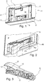
- FIG. 1 shows a section on an inner side 2 a of a carcass rear wall 2 of a furniture body 3 with an attached ejection device according to the invention 1.
- the ejection device 1 is as Aufsteckbauteil for plugging Profile rails 4, 5 is formed, wherein the attached ejection device 1 occupies an area between the vertically aligned parallel rails 4 and 5.
- the ejection device 1 is used for ejecting a in the FIGS. 4 and 5 illustrated drawer 11 and 13, which is accommodated on the furniture body 3 between two opposite and the carcass rear wall 2 at right angles to the side walls extending slidably over two Auszugmaschineen (not shown). To open or eject a drawer, the ejector 1 acts z. B.
- the ejection lever 9 is driven about a vertical pivot axis S in the direction of P1 swung out and opposite in direction P2 can be pivoted ,
- a drive unit for swinging in and out of the ejection lever 9 is in particular an electric drive motor or electric motor in question.
- the approximately cuboid ejection device 1 is mounted on the inside 2a of the body rear wall 2 via the existing thereon vertically extending rails 4, 5 above a horizontal cross rail 6 or attached.
- mounting portions 7, 8 are provided with slightly elastically bendable mounting jaws on the ejection device 1 on both sides, which can be snapped on appropriate mating portions of the rails 4, 5.
- the ejection device 1 is supplied with energy via a power supply and controlled or controlled by means of a control unit.
- the ejection lever 9 is located in the fully pivoted in the direction P2 and resting state according to the FIGS. 1, 2 . 4 and 5 partially recessed in a receiving recess 10 of the ejection device 1, wherein the ejection lever 9 projects over a planar flat front side 1a of the ejection device 1 something.
- the ejection device 1 is used in a furniture such as a kitchen furniture, the movable over Guide units on the furniture body 3 movably received furniture drawer 11 and 13 from a fully inserted on the furniture body 3 position according to the FIGS. 4 and 5 in the direction of P3.
- pivoted ejection lever 9 which abuts the rear of the steel rear wall 14 and the wooden rear wall 11a, driven in the direction P1, so that the drawer 11 and 13 is also driven ejected until a discharge contact of the ejection lever 9 with the wooden rear wall 11a or the steel rear wall 14 is released and the drawer 11 or 13 is further movable in the direction P3, for example, slows down without external action and expires or is actively pulled further by a person.
- the driven ejection of the drawer 11, 13 can be initiated via the person who wants to open the drawer 11, 13, for example by tapping or pushing the drawer 11, 13 or their front panel in the direction of the body rear wall 2, whereby the ejection lever 9 is pushed from the drawer rear wall 11a and 14 from the resting starting position in the direction P2.
- a triggering command takes place, which is detected for example via a sensor in the device, which registers the pushing in of the ejection lever 9.
- the sensor communicates with the control unit, which causes the drive unit for driven swinging out of the ejection lever 9 in the direction of P1 and thus ejects the drawer 11, 13 forward according to P3.
- the ejection lever 9 comprises in the new state or in the installed state of the ejection device 1, a neck portion 15 and a base portion 17, wherein the neck portion 15 is connected via a prepared designed separation region 16 with the base part 17.
- the separating region 16 can be formed in different ways and is in particular tuned so that the neck portion 15 along a defined predetermined dividing line reproducible and easier, for example, by hand or optionally with the aid of a simple tool from the base member 17 selectively removed can be.
- the base part 17 constitutes the remaining part of the ejection lever 9.
- the ejection lever 9 fulfills its intended function by swinging out to eject the inserted drawer 11 or 13.
- the abutment lever 9 existing neck portion 15 provides the abutment portion 12 and when removed neck portion 15, the base member 17 a contact portion 12 '(s. FIG. 4 ).
- the contact section 12 or 12 ' arrives at the ejection with the drawer rear wall 11a, 14 in ejection contact.
- the shape or contour of the contact section 12 ' is modeled on the shape or contour of the contact section 12.
- FIG. 4 shows from the side of a highly schematic and fragmentary attached to the carcass rear wall 2 ejector 1 with pivoted ejection lever 9 and the fully inserted into the furniture body 3 drawer 11 in not to scale.
- the existing between parallel side walls of the drawer board-like wooden back wall 11a of the drawer 11 is formed of solid material and is made of wood.
- the neck portion 15 is removed, so that the abutment portion 12 'of the base member 17 abuts against the rear side of the wood rear wall 11a of the fully inserted drawer 11.
- the rear side of the wood rear wall 11a of the drawer 11 is spaced a distance s1 from the front 1a of the ejector 1.
- FIG. 5 shows the same furniture body 3 with the drawer 13 with the steel rear wall 14 of a profiled steel material, wherein a rear wall of the rear wall 14 of the steel rear wall 14 facing the carcass rear wall 2, on which the ejection lever 9 engages with the abutment portion 12 of the lug portion 15 during ejection, compared with FIG the drawer 11 is further away or has a greater distance s2 to the front side 1a of the ejection device 1.
- the drawer 13 in the fully retracted or closed state on the furniture body 3 can not or should not continue as in accordance FIG. 5 shown to the body rear wall 2 are inserted, otherwise a front of a front of the drawer 13 (not shown), which closes the front of the drawer 13 in the direction P3, not flush but correspondingly set back to end sides of the side walls of the furniture body or the necessary length of Einschiebeumble would not be possible with the rail guide the drawer 13 or only with additional installation effort.
- the distance difference .DELTA.s be compensated with the ejection lever 9, depending on whether the wood rear wall 11a or the steel rear wall 14 is present. This is done with the neck portion 15, which is optionally present on the ejection lever 9, according to FIG. 5 , or decreased, what is FIG. 4 shows.
- FIG. 6 shows the ejection lever 9 according to FIG. 3 schematized or FIG. 7 alone the neck portion 15 each from the side.
- the contact points of the abutment portion 12 with corresponding locations of the portion 14a of the rear side of the steel rear wall 14 extend in the course of an ejection operation of the drawer 13 along the ejection lever 9 over a range a. Accordingly, a radius of the respective contact point to the pivot axis S changes from R1 to R2 with R2> R1 (s. FIG. 6 ).
- the separation area 16 may be defined, for example, by at least one be prepared recess or be realized on a prepared predetermined breaking area with predetermined breaking points for easy breaking off of the neck portion 15 of the base member 17.
- FIG. 7 shows the neck portion 15 in an individual view additionally with interrupted contours of a spring tongue 19 at a front end of the neck portion 15, which different degrees elastic bending of the spring tongue 19 are indicated, which is due to the ejection process acting ejection forces from the ejection lever 9 to the drawer 13, whereby the ejection lever 9 is acted upon in the loading direction P4 with a counterforce.
- FIG. 8 shows the ejection lever 9 with the spring tongue 19 in the unstressed state and indicated in a bent state in which a rounded front edge 19a of the spring tongue 19 sweeps over a bending radius r, for example, a load on the ejection lever 9 when ejecting a heavy drawer.
- FIGS. 6 to 10 illustrate the formation of elastically evasive and recoverable spring tongue 19 of the neck portion 15, wherein the neck portion 15 is formed in particular of a suitable plastic.
- the spring tongue 19 forms an extension of a part or a wall 20 of a loop-shaped spring 18, which has a free from the side fork-like spring opening 21, which is enclosed by the elastic thin resilient wall 20.
- a material-free area is provided in the loading direction P4 behind a wall section 20a of the wall 20 in the area of the contact section 12, whereby in addition to the elastic possibility of deflection of the spring tongue 19, the wall section 20a and further sections of the Wall 20 have resettable spring properties under load.
- the neck portion 15 is supported in the attached state with another wall portion 20b of the wall 20 of the spring 18 on the surface of the portion of the base part 17, which forms the contact area 12 'when the neck portion 15 is not present.
Landscapes
- Drawers Of Furniture (AREA)
Description
Bei modernen Möbeln ist es bekannt, ein an einem Möbelkorpus bewegbar aufgenommenes Möbelteil wie einer Schublade oder einer Möbelklappe durch eine Ausstoßvorrichtung aus einer am Möbelkorpus eingefahrenen oder eingeschwenkten Position in eine herausbewegte bzw. ausgestoßene Position zu bringen. Dies kann mit Hilfe eines angetrieben bewegbaren Ausstoßelements der Ausstoßvorrichtung erfolgen, zum Beispiel mit einem Ausstoßhebel. Das Ausstoßelement weist einen Anlageabschnitt auf, der beim Herausbewegen des bewegbaren Möbelteils zumindest zeitweise in Kontakt mit dem Teil des Möbels bringbar ist, an dem die Vorrichtung nicht angebracht ist.In modern furniture, it is known to bring a movably received on a furniture body furniture part such as a drawer or a furniture flap by an ejector from a retracted or pivoted to the furniture body position in a moved out or ejected position. This can be done by means of a driven movable ejection element of the ejection device, for example with an ejection lever. The ejection element has an abutment portion, which is at least temporarily brought into contact with the part of the furniture on moving out of the movable furniture part, to which the device is not attached.
Im Hinblick auf vielfältige Einsatzmöglichkeiten der Ausstoßvorrichtung, sind entsprechende Maßnahmen an der Vorrichtung vorzusehen.With regard to a variety of possible uses of the ejection device, appropriate measures must be provided on the device.
Die
Aus der
Aufgabe der vorliegenden Erfindung ist es, einleitend bezeichnete Vorrichtungen bzw. Möbel zu verbessern, so dass ein technisch und wirtschaftlich vorteilhafter Einsatz der Vorrichtung möglich ist. Insbesondere soll mit der bereitgestellten Vorrichtung ein Einsatz für unterschiedlich gestaltete bewegbare Möbelteile flexibel möglich sein.Object of the present invention is to improve initially designated devices or furniture, so that a technically and economically advantageous use of the device is possible. In particular, should be possible flexibly with the provided device, an insert for differently shaped movable furniture parts.
Diese Aufgabe wird durch die unabhängigen Ansprüche gelöst.This object is solved by the independent claims.
Die abhängigen Ansprüche betreffen vorteilhafte Varianten der Erfindung.The dependent claims relate to advantageous variants of the invention.
Die Erfindung geht aus von einer Vorrichtung zum Ausstoßen eines Möbelteils, das an einem feststehenden Möbelteil bewegbar aufgenommen ist, wobei die Vorrichtung für eine Anbringung an einem der beiden Möbelteile vorgesehen ist und einen an der Vorrichtung gelagerten und über eine Antriebseinheit antreibbaren Ausstoßhebel umfasst, der für einen Ausstoßvorgang aus einer Startposition an der Vorrichtung heraus antreibbar ist, so dass ein Anlageabschnitt am Ausstoßhebel mit dem anderen Möbelteil in Kontakt bringbar ist, um das bewegbar aufgenommene Möbelteil in eine Öffnungsrichtung relativ zum feststehenden Möbelteil auszustoßen. Die Vorrichtung ist insbesondere so abgestimmt, dass mit Erreichen des Endes des Ausstoßvorgangs durch den Ausstoßhebel ein Kontakt zwischen dem Anlageabschnitt am Ausstoßhebel und dem anderen Möbelteil insbesondere unter einem Weiterbewegen des Möbelteils in Öffnungsrichtung aufgehoben wird. Die Vorrichtung kann am Möbelkorpus angebracht sein, wobei der Ausstoßhebel mit dem Anlageabschnitt an dem bewegbaren Möbelteil in Kontakt bringbar ist. Alternativ ist die Vorrichtung am bewegbaren Möbelteil angeordnet und der Anlageabschnitt gelangt am Möbelkorpus in Kontakt, wobei die Vorrichtung am bewegbaren Möbelteil, das mit einem Ausstoßvorgang vom Möbelkorpus abstoßbar ist, mitbewegt wird.The invention relates to a device for ejecting a furniture part, which is movably received on a stationary furniture part, wherein the device is provided for attachment to one of the two furniture parts and comprises a mounted on the device and driven by a drive unit ejection lever, the an ejection operation from a start position on the device can be driven out, so that a contact portion on the ejection lever can be brought into contact with the other furniture part to eject the movably received furniture part in an opening direction relative to the stationary furniture part. The device is in particular tuned so that upon reaching the end of the ejection operation by the ejection lever, a contact between the abutment portion on the ejection lever and the other furniture part is repealed in particular under a further movement of the furniture part in the opening direction. The device may be mounted on the furniture body, wherein the ejection lever can be brought into contact with the abutment portion on the movable furniture part. Alternatively, the device is arranged on the movable furniture part and the contact section reaches the furniture body in contact, wherein the device on the movable furniture part, with an ejection process from the furniture body is repulsive, is moved.
Der Kern der Erfindung liegt darin, dass der Ausstoßhebel einen Ansatzabschnitt aufweist, welcher entlang eines vorhandenen Trennbereichs vom verbleibenden Teil des Ausstoßhebels wahlweise abnehmbar ist, womit eine Tiefenabmessung des Ausstoßhebels im Bereich des Anlageabschnitts abhängig vom Vorhandensein des Ansatzabschnitts am Ausstoßhebel derart vorgebbar ist, dass die Tiefenabmessung des Ausstoßhebels bei abgenommenem Ansatzabschnitt verringert ist gegenüber der Tiefenabmessung des Ausstoßhebels bei nicht abgenommenem Ansatzabschnitt. Der Ausstoßhebel setzt sich demgemäß aus dem Ansatzabschnitt mit dem verbleibenden Teil des Ausstoßhebels zum Beispiel einem Basisteil zusammen, oder der Ausstoßhebel weist allein den verbleibenden Teil bzw. das Basisteil gegenüber der Variante mit dem Ansatzabschnitt auf.The essence of the invention is that the ejection lever has a neck portion which is selectively removable along an existing separation area from the remaining part of the ejection lever, whereby a depth dimension of the ejection lever in the region of the abutment portion depending on the presence of the neck portion on the ejection lever is predetermined such that the Depth dimension of the ejection lever is reduced with the neck portion removed is compared to the depth dimension of the ejection lever with not removed neck portion. The ejection lever is accordingly composed of the neck portion with the remaining part of the ejection lever, for example, a base part, or the ejection lever alone has the remaining part or the base part opposite to the variant with the neck portion.
Vorteilhafterweise kann der Ausstoßhebel und damit die Vorrichtung individuell an unterschiedliche Einsatzzwecke angepasst werden, insbesondere auf unterschiedlich gestaltete Abstandsmaße unterschiedlicher Möbel. Das Abstandsmaß bezieht sich bei geschlossenem Möbelteil relativ zum Möbelkorpus, insbesondere auf einen Abstand zwischen gegenüberliegenden beabstandeten Wandabschnitten, zwischen denen die Vorrichtung anbringbar bzw. wirksam ist. Konkret sind das zum Beispiel eine Innenseite einer Rückwand des Möbelkorpus, an der die Vorrichtung zum Beispiel auf Höhe eines auszustoßenden Möbelteils anbringbar ist, und eine Außenseite einer Rückwand des mit der Vorrichtung auszustoßenden bewegbaren Möbelteils wie einer Schublade. Dieser Abstand zwischen den Rückwänden kann je nach Ausgestaltung bzw. Dicke der Schubladenrückwand unterschiedlich sein. Zum Beispiel ist der Abstand zwischen den Rückwänden verschieden, abhängig davon, ob die Rückwand des bewegbaren Möbelteils bzw. der Schublade als Holz- oder Metallrückwand ausgebildet ist. Holzrückwände bedingen in der Regel einen geringeren Abstand, so dass der Ausstoßhebel ohne Ansatzabschnitt die geeignete Tiefenabmessung im Bereich des Anlageabschnitts aufweist, um den geringeren Abstand zu überbrücken, bei vollständig an der Vorrichtung eingeschwenktem Ausstoßhebel. Die Tiefenabmessung ist demgemäß auf eine Start-Position des Ausstoßhebels bei einem vollständig zurückgeschwenkten Ausstoßhebel in einer Warteposition vor einem Ausstoßvorgang bezogen und auf das am Möbelkorpus vollständig eigeschobene bzw. geschlossene bewegbare Möbelteil.Advantageously, the ejection lever and thus the device can be adapted individually to different purposes, in particular to differently designed distance measurements of different furniture. The distance measure relates to the closed furniture part relative to the furniture body, in particular to a distance between oppositely spaced wall sections, between which the device is attachable or effective. Specifically, these are, for example, an inner side of a rear wall of the furniture body to which the device is attachable, for example, at the height of a furniture part to be ejected, and an outer side of a rear wall of the movable furniture part to be ejected with the device, such as a drawer. This distance between the rear walls can be different depending on the design or thickness of the drawer rear wall. For example, the distance between the rear walls is different, depending on whether the rear wall of the movable furniture part or the drawer is formed as a wood or metal back wall. Wooden rear walls usually require a smaller distance, so that the ejection lever without neck portion has the appropriate depth dimension in the region of the contact section, to the smaller distance to bridge, with fully pivoted to the device ejection lever. The depth dimension is accordingly related to a start position of the ejection lever with a fully swung-back ejection lever in a waiting position before a discharge operation and on the furniture body completely eigeschobene or closed movable furniture part.
Bei einer Metall-Schubladenrückwand ist der Abstand zur Möbelkorpus-Rückwand in der Regel größer, womit der Ansatzabschnitt am Ausstoßhebel nötig ist, um den größeren Abstand entsprechend komplett überbrücken zu können, also um in Anlage an der Außenseite der Schubladen-Rückwand zu kommen, bei eingeschwenktem Ausstoßhebel und bei relativ zum Möbelkorpus eingeschobener Schublade.In a metal drawer rear wall, the distance to the furniture body rear wall is usually larger, so the neck portion on the ejection lever is necessary in order to completely bridge the larger corresponding distance, so to come into contact with the outside of the drawer rear wall, at swung ejection lever and inserted relative to the furniture body drawer.
Um diese je nach Art der z. B. Schubladenrückwand möglichen Abstandsunterschiede auszugleichen, müssen bisher unterschiedliche Ausstoßhebel mit unterschiedlichen Tiefenabmessungen im Bereich des Anlageabschnitts vorgesehen werden, was nachteilig bzw. aufwändig ist bzw. einen erhöhten Herstellungs-, Bereitstellungs- und Montageaufwand mit sich bringt.To this depending on the type of z. B. drawer rear wall compensate for possible differences in distance, so far different ejector must be provided with different depth dimensions in the area of the contact section, which is disadvantageous or expensive or brings increased manufacturing, Bereitstellungs- and assembly costs.
Der betrachtete Abstand ist auf die sich gegenüberliegenden Rückwandabschnitte bezogen, insbesondere ein in horizontaler Richtung gemessener Abstand der Rückwandbereiche, zwischen denen die Vorrichtung wirksam ist, was den Anbringbereich der Vorrichtung am einen Möbelteil einerseits und den horizontal gegenüberliegenden Rückwandabschnitt des anderen Möbelteils andererseits betrifft, der von dem Ausstoßhebel beaufschlagt wird.The considered distance is related to the opposite rear wall sections, in particular a measured in the horizontal direction distance of the rear wall areas, between which the device is effective, which concerns the mounting portion of the device on a furniture part on the one hand and the horizontally opposite rear wall portion of the other furniture part on the other hand the ejection lever is acted upon.
Die Tiefenabmessung des Ausstoßhebels ist bezogen auf eine Richtung, welche durch die Bewegungsrichtung des bewegbaren Möbelteils auf einem ersten Streckenabschnitt des ausgestoßenen Möbelteils vorgegeben ist. Dies bedeutet beispielsweise bei einer auszustoßenden Schublade die Ausschieberichtung der Schublade.The depth dimension of the ejection lever is based on a direction predetermined by the moving direction of the movable furniture part on a first stretch of the ejected furniture part. This means, for example, in a drawer to be ejected the Ausschieberichtung the drawer.
Weiter ist es vorteilhaft, dass der Ansatzabschnitt den Anlageabschnitt bereitstellt, wenn der Ansatzabschnitt am Ausstoßhebel angebracht ist. Damit ist der Teil des Ausstoßhebels, der zu Beginn des Ausstoßvorgangs mit dem anderen Möbelteil in Kontakt ist, durch den Ansatzabschnitt gebildet. Der Ansatzabschnitt umfasst insbesondere einen in Schwenkrichtung des Ausstoßhebels vorderen geraden oder gebogenen Endbereich des Ausstoßhebels.Further, it is advantageous that the nose portion provides the abutting portion when the nose portion is attached to the ejection lever. Thus, the part of the ejection lever, which is in contact with the other furniture part at the beginning of the ejecting operation, is formed by the boss portion. In particular, the attachment portion comprises a straight or bent end region of the ejection lever in the pivoting direction of the ejection lever.
Es ist überdies vorteilhaft, dass der Ausstoßhebel derart ausgebildet ist, dass im Zustand der Vorrichtung mit dem vom Ausstoßhebel abgenommenen Ansatzabschnitt der Anlageabschnitt am verbleibenden Teil des Ausstoßhebels bereitgestellt ist. Damit ist die volle Ausstoßfunktion des Ausstoßhebels auch bei abgenommenem Ansatzabschnitt erfüllt. Die Form des vom verbleibenden Teil des Ausstoßhebels gebildeten Anlageabschnitts entspricht vorteilhaft der Form des vom Ansatzabschnitt gebildeten Anlageabschnitts. Ein wirksamer Kantenverlauf des Anlageabschnitt ist bevorzugt gebogen gestaltet, was insbesondere vorteilhaft ist, da ein Kontakt zwischen dem Anlageabschnitt und dem anderen Möbelteil über einen vollständigen Ausstoßvorgang betrachtet in der Regel nicht an einem ortsfesten Bereich des Anlageabschnitts stattfindet, sondern sich verändert bzw. entlang einer Strecke am Anlageabschnitt bewegt. Zum Beispiel wandert der Kontaktpunkt am Anlageabschnitt, welcher den Kontakt zum anderen Möbelteil herstellt, während eines Ausstoßvorgangs von einer Stelle am Anlageabschnitt mit einem radial geringerem Abstand R1 zu einer Schwenkachse des Ausstoßhebels zu einer Stelle, die einen größeren radialen Abstand R2 zur Ausstoßhebel-Schwenkachse aufweist, also R2 größer als R1 ist. Der radiale Abstand R1 zur Schwenkachse ist insbesondere der Abstand des Kontaktpunktes des Anlageabschnitts mit dem anderen Möbelteil bei ruhendem geschlossenen Möbelteil, wohingegen der radiale Abstand R2 insbesondere dem Abstand des Kontaktpunktes des Anlageabschnitts mit dem anderen Möbelteil zugehörig ist, in welchem der Kontakt zwischen dem Anlageabschnitt und dem anderen Möbelteil am Ende eines Ausstoßvorgangs aufgehoben wird.It is also advantageous that the ejection lever is designed such that in the state of the device with the removed from the ejection lever neck portion of the abutment portion is provided on the remaining part of the ejection lever. Thus, the full ejection function of the ejection lever is met even with removed approach section. The shape of the abutment portion formed by the remaining part of the ejection lever advantageously corresponds to the shape of the abutment portion formed by the neck portion. An effective edge course of the abutment portion is preferably curved, which is particularly advantageous because contact between the abutment portion and the other furniture part considered over a complete ejection process usually does not take place at a fixed area of the abutment portion, but changed or along a route moved at the investment section. For example, the contact point on the abutment portion which makes contact with the other furniture part migrates from a location on the abutment portion with a radially smaller distance R1 to a pivot axis of the ejection lever to a location having a greater radial distance R2 to the ejector pivot axis during a puffing operation , so R2 is greater than R1. The radial distance R1 to the pivot axis is in particular the distance of the contact point of the abutment portion with the other furniture part at rest closed furniture part, whereas the radial distance R2 in particular the distance of the contact point of the abutment portion with the other furniture part is associated, in which the contact between the contact portion and the other furniture part at the end of a Ejection operation is canceled.
Die Wirkungsweise des Ausstoßhebels bzw. des Anlageabschnitts auf das andere Möbelteil während eines Ausstoßvorgangs ist insbesondere identisch, wenn man die beiden Gestaltungsvarianten des Ausstoßhebels mit und ohne Ansatzabschnitt vergleicht. Das bedeutet, dass ein ausgestoßenes Möbelteil, zum Beispiel eine Schublade mit einer Holzrückwand oder mit einer Stahlrückwand, mit der gleichen Bewegungs- bzw. Ausstoßcharakteristik ausgestoßen wird, egal ob der Ausstoßhebel mit dem Ansatzabschnitt, bei vorhandener Stahlrückwand, oder ohne den Ansatzabschnitt, bei einer Holzrückwand, wirksam ist.The mode of action of the ejection lever or of the abutment section on the other furniture part during an ejection process is in particular identical if one compares the two design variants of the ejection lever with and without neck section. This means that an ejected furniture part, for example a drawer with a wooden rear wall or with a steel rear wall, is ejected with the same movement or ejection characteristic, regardless of whether the ejection lever with the neck portion, with existing steel rear wall, or without the neck portion, at a Wooden back wall, is effective.
Gemäß einer vorteilhaften Ausgestaltung der Erfindung umfasst der Trennbereich vorbereitete Ausnehmungen. Die vorbereiteten Ausnehmungen können beispielsweise als Sollbruchstellen wirken. Damit kann der Ansatzabschnitt erleichtert und definiert vom Basisteil abgenommen werden.According to an advantageous embodiment of the invention, the separation region comprises prepared recesses. The prepared recesses can act, for example, as predetermined breaking points. Thus, the neck portion can be relieved and defined removed from the base part.
Eine vorteilhafte Modifikation der Erfindung zeichnet sich dadurch aus, dass der Trennbereich vorbereitete Verbindungsmittel aufweist, welche eine Einrichtung und Lösung der Verbindung des Ansatzabschnitts am verbleibenden Teil des Ausstoßhebels ermöglicht. Insbesondere kann die Verbindung des Ansatzabschnitts am verbleibenden Teil des Ausstoßhebels reversibel lösbar einrichtbar und aufhebbar sein. Vorteilhaft ist in einem einzigen Arbeitsschritt insbesondere manuell bzw. werkzeuglos der Ansatzabschnitt abnehmbar und ggf. wieder ansetzbar.An advantageous modification of the invention is characterized in that the separation region has prepared connection means which allows a device and solution of the connection of the neck portion on the remaining part of the ejection lever. In particular, the connection of the attachment portion on the remaining part of the ejection lever can be set reversibly detachable and canceled. It is advantageous in a single step, in particular manually or without tools, the neck portion removable and possibly re-attachable.
Eine weitere vorteilhafte Erfindungsvariante betrifft Verbindungsmittel, welche für eine Verbindung des Ansatzabschnitts mit dem verbleibenden Teil des Ausstoßhebels ausgebildet sind, wobei mit den Verbindungsmitteln eine Steckverbindung zwischen dem Ansatzabschnitt und dem verbleibenden Teil des Ausstoßhebels einrichtbar ist. Insbesondere kann vorteilhaft eine lösbare Verbindung eingerichtet werden. Eine Steckverbindung ist zudem einfach und technisch zuverlässig realisierbar.A further advantageous variant of the invention relates to connecting means, which are designed for a connection of the attachment portion with the remaining part of the ejection lever, wherein with the connection means a plug connection between the attachment portion and the remaining part of the ejection lever can be established. In particular, advantageously, a detachable connection can be established. A plug connection is also easy and technically reliable.
Vorteilhafterweise sind die Verbindungsmittel für eine Verbindung des Ansatzabschnitts mit dem verbleibenden Teil des Ausstoßhebels ausgebildet, wobei mit den Verbindungsmitteln eine Rastverbindung mit Rastmitteln zwischen dem Ansatzabschnitt und dem verbleibenden Teil des Ausstoßhebels einrichtbar ist. Eine Rastverbindung über Rastmittel bleibt auch bei auftretenden Belastungen sicher bzw. dauerhaft eingerichtet.Advantageously, the connecting means are formed for a connection of the neck portion with the remaining part of the ejection lever, wherein with the connecting means a latching connection with locking means between the neck portion and the remaining part of the ejection lever can be set. A locking connection via latching means remains safe or permanent even when loads occur.
Beispielsweise kann die Rastverbindung durch eine Schnappverbindung mit Schnappmitteln beispielsweise als lösbare Verbindung bereitgestellt sein. Der Ansatzabschnitt kann über die Rastverbindung ggf. einklipsbar oder einschiebbar sein.For example, the latching connection can be provided by a snap connection with snap means, for example, as a releasable connection. The neck portion may optionally be clipped or inserted via the snap-in connection.
Vorteilhafterweise ist außerdem, dass die Verbindungsmittel einen Schnapphaken am Ansatzabschnitt umfassen, welcher mit einem auf den Schnapphaken abgestimmten Gegenabschnitt am verbleibenden Teil des Ausstoßhebels für die Ausbildung einer Verbindung zwischen dem Ansatzabschnitt und dem verbleibenden Teil des Ausstoßhebels ausgestaltet sind. Insbesondere sind mehrere gleichartige Schnapphaken für die lösbare Verbindung eingerichtet. Die Anordnung der mehreren Schnapphaken ist beispielsweise in einem in Längserstreckung des Ansatzabschnitts vorderen und hinteren Bereich des Ansatzabschnitts realisiert, was mechanisch vorteilhaft ist.Advantageously, in addition, the connecting means comprise a snap hook on the neck portion, which are configured with a matched to the snap hook counter portion on the remaining part of the ejection lever for forming a connection between the neck portion and the remaining part of the ejection lever. In particular, several similar snap hooks are set up for the detachable connection. The arrangement of the plurality of snap hooks is realized, for example, in a longitudinal region of the attachment portion front and rear portion of the neck portion, which is mechanically advantageous.
Weiter ist es vorteilhaft, dass der Ansatzabschnitt vorbereitete Federmittel derart aufweist, dass der Anlageabschnitt, welcher durch den Ansatzabschnitt bereitgestellt ist, bei einer Druckbelastung entsprechend einer Belastung bei einem Ausstoßvorgang des bewegbaren Möbelteils elastisch ausweichbar und rückstellbar ist. Auf diese Weise können unterschiedlich hohe Kräfte vom Ausstoßhebel bei einem Ausstoßvorgang auf das bewegbare Möbelteil kontrolliert übertragen werden, wobei eine punktuelle Überlastung der betreffenden Bauteile vermieden und Beschädigungen entgegengewirkt wird.Further, it is advantageous that the boss portion has prepared spring means such that the abutment portion provided by the boss portion is elastically deflected and recoverable under a pressure load corresponding to a load in a jetting operation of the movable furniture member. In this way, different levels of forces from the ejection lever can be transmitted controlled in a discharge operation on the movable furniture part, with a point overloading of the components concerned avoided and Damage is counteracted.
Vorteilhafterweise umfasst der Ansatzabschnitt vorbereitete Federmittel mit einem schlaufenförmigen Federbauteil mit einer federnden Materialzunge, wobei über eine Vorderseite der Materialzunge ein Kontakt mit dem anderen Möbelteil bei einem Ausstoßvorgang erfolgt, und wobei sich an eine Rückseite der Materialzunge ein materialfreier Bereich anschließt, der einen Ausweichraum für die Materialzunge bei einer Druckbelastung auf die Vorderseite der Materialzunge bereitstellt. Dies stellt eine materialsparende und kompakte Ausbildung des Ansatzabschnittes dar.Advantageously, the approach portion comprises prepared spring means with a loop-shaped spring member having a resilient material tongue, wherein via a front of the material tongue a contact with the other furniture part takes place during an ejection process, and wherein a material-free area adjoins a back of the material tongue, which has an alternative space for the Material tongue provides a pressure load on the front of the tongue material. This represents a material-saving and compact design of the approach section.
Es ist überdies von Vorteil, dass die Federmittel ein schlaufenförmiges Federbauteil mit einem Stützsteg umfassen, über welchen sich der am Ausstoßhebel angebrachte Ansatzabschnitt an dem verbleibenden Teil des Ausstoßhebels abstützt, wobei zwischen dem Stützsteg und dem Anlageabschnitt ein materialfreier Bereich vorhanden ist. Diese Ausbildung ist stabil und mit geringem Materialaufwand realisierbar.It is also advantageous that the spring means comprise a loop-shaped spring member having a support bar, via which the ejection lever attached to the projection portion is supported on the remaining part of the ejection lever, wherein between the support bar and the contact portion a material-free area is present. This training is stable and can be realized with little cost of materials.
Die Erfindung bezieht sich außerdem auf ein Möbel mit einem feststehenden Möbelteil, an dem ein bewegbares Möbelteil aufgenommen ist, wobei eine der oben genannten Vorrichtungen vorhanden ist. Damit lassen sich an dem betreffenden Möbel die oben diskutierten Vorteile erreichen. Insbesondere weist das Möbel einen Möbelkorpus mit einer Schublade und einer Ausstoßvorrichtung für die Schublade auf, welche den Ausstoßhebel umfasst. Die Ausstoßvorrichtung wirkt insbesondere zwischen einer Rückseite der Schublade und einer Innenseite einer Möbelkorpus-Rückwand.The invention also relates to a piece of furniture with a fixed furniture part, on which a movable furniture part is received, wherein one of the above-mentioned devices is present. This can be achieved on the furniture in question the advantages discussed above. In particular, the furniture has a furniture body with a drawer and a discharge device for the drawer, which comprises the ejection lever. In particular, the ejection device acts between a rear side of the drawer and an inner side of a furniture body rear wall.
Weitere Merkmale und Vorteile der Erfindung sind anhand einer in den Figuren dargestellten erfindungsgemäßen Ausstoßvorrichtung näher erläutert. Im Einzelnen zeigt:
Figur 1- eine erfindungsgemäße Vorrichtung, die an einem Möbel angebracht ist, in perspektivischer Ansicht,
Figur 2- einen vergrößerten Ausschnitt der Anordnung gemäß
Figur 1 , Figur 3- den Ausstoßhebel gemäß der Vorrichtung aus
den Figuren 1 und 2 in perspektivischer Einzelansicht schräg von oben, Figur 4- eine schematisierte Seitenansicht auf die
Vorrichtung gemäß Figur 1 und 2 im eingebauten Zustand an einem teilweise gezeigten Möbel mit einer Schublade, Figur 5- die erfindungsgemäße Vorrichtung im eingebauten Zustand an einem teilweise gezeigten Möbel mit einer zur Schublade gemäß
Figur 4 alternativen Schublade, Figur 6- stark schematisiert der in
Figur 3 Figur 7- einen Ansatzabschnitt des Ausstoßhebels gemäß
Figur 6 , - Figur 8
- den
Ausstoßhebel gemäß Figur 3 in einer weiteren perspektivischen Ansicht und Figur 9 und 10- den Ansatzabschnitt des Ausstoßhebels gemäß
Figur 8 in zwei unterschiedlichen perspektivischen Ansichten.
- FIG. 1
- a device according to the invention, which is attached to a furniture, in perspective view,
- FIG. 2
- an enlarged section of the arrangement according to
FIG. 1 . - FIG. 3
- the ejection lever according to the device of the
Figures 1 and 2 in a perspective single view diagonally from above, - FIG. 4
- a schematic side view of the device according to
FIGS. 1 and 2 when installed on a partially shown piece of furniture with a drawer, - FIG. 5
- the device according to the invention when installed on a partially shown furniture with a drawer according to
FIG. 4 alternative drawer, - FIG. 6
- strongly schematized in
FIG. 3 shown ejector lever from the side, - FIG. 7
- a neck portion of the ejection lever according to
FIG. 6 . - FIG. 8
- the ejection lever according to
FIG. 3 in a further perspective view and - FIGS. 9 and 10
- the neck portion of the ejection lever according to
FIG. 8 in two different perspective views.
Die angenähert quaderförmige Ausstoßvorrichtung 1 ist an der Innenseite 2a der Korpusrückwand 2 über die daran vorhandenen vertikal verlaufende Profilschienen 4, 5 oberhalb einer horizontalen Querschiene 6 anmontiert bzw. aufgesteckt. Hierfür sind an der Ausstoßvorrichtung 1 an beiden Seiten Befestigungsabschnitte 7, 8 mit geringfügig elastisch aufbiegbaren Befestigungsbacken vorhanden, die an passenden Gegenabschnitten der Profilschienen 4, 5 aufschnappbar sind.The approximately
Die Ausstoßvorrichtung 1 wird über eine Energieversorgung mit Energie versorgt und mittels einer Kontrolleinheit kontrolliert bzw. gesteuert. Der Ausstoßhebel 9 befindet sich im vollständig in Richtung P2 eingeschwenkten und ruhenden Zustand gemäß der
Die Ausstoßvorrichtung 1 dient dazu, bei einem Möbel wie beispielsweise einem Küchenmöbel, die bewegbar über Führungseinheiten an dem Möbelkorpus 3 bewegbar aufgenommene Möbelschublade 11 bzw. 13 aus einer vollständig am Möbelkorpus 3 eingeschoben Stellung gemäß der
Das angetriebene Ausstoßen der Schublade 11, 13 kann über die Person, welcher die Schublade 11, 13 öffnen möchte, initiiert werden, beispielsweise durch ein Antippen bzw. Eindrücken der Schublade 11, 13 bzw. deren Frontblende in Richtung zur Korpusrückwand 2, womit der Ausstoßhebel 9 von der Schubladenrückwand 11a bzw. 14 aus der ruhenden Ausgangsstellung in Richtung P2 hineingedrückt wird. Dabei findet ein Auslösebefehl statt, der zum Beispiel über einen Sensor in der Vorrichtung erfasst wird, der das Hineindrücken des Ausstoßhebels 9 registriert. Der Sensor kommuniziert mit der Kontrolleinheit, welche die Antriebseinheit zum angetriebenen Herausschwenken des Ausstoßhebels 9 in Richtung P1 veranlasst und so die Schublade 11, 13 nach vorne gemäß P3 ausstößt.The driven ejection of the
Der Ausstoßhebel 9 umfasst im Neuzustand bzw. im Einbauzustand der Ausstoßvorrichtung 1 einen Ansatzabschnitt 15 und ein Basisteil 17, wobei der Ansatzabschnitt 15 über einen vorbereitet ausgestalteten Trennbereich 16 mit dem Basisteil 17 verbunden ist. Der Trennbereich 16 kann auf unterschiedliche Weise ausgebildet sein und ist insbesondere so abgestimmt, dass der Ansatzabschnitt 15 entlang einer definierten vorgebbaren Trennlinie reproduzierbar und erleichtert zum Beispiel von Hand bzw. ggf. unter Zuhilfenahme eines einfachen Werkzeugs vom Basisteil 17 wahlweise entfernt werden kann. Bei entferntem Ansatzabschnitt 15 stellt das Basisteil 17 den verbleibenden Teil des Ausstoßhebels 9 dar. In beiden Zuständen, mit oder ohne Ansatzabschnitt 15, erfüllt der Ausstoßhebel 9 seine bestimmungsgemäße Funktion durch Ausschwenken zum Ausstoßen der eingeschobenen Schublade 11 bzw. 13. Dies bedeutet auch, dass der am Ausstoßhebel 9 vorhandenen Ansatzabschnitt 15 den Anlageabschnitt 12 bereitstellt bzw. bei abgenommenem Ansatzabschnitt 15 das Basisteil 17 einen Anlageabschnitt 12' (s.
Demgegenüber zeigt
Bezogen auf die rückwärtige Seite der Holzrückwand 11a der Schublade 11 ist die rückwärtige Seite der Stahlrückwand 14 der Schublade 13 zum Inneren der Schublade 13 mit einem standardmäßig vorgegebenen Maß Δs = s2 - s1 versetzt bzw. weist ein entsprechendes Versatzmaß auf. Die Schublade 13 im vollständig eingefahrenen bzw. geschlossenen Zustand am Möbelkorpus 3 kann bzw. soll aber nicht weiter als gemäß
Deshalb ist es vorteilhaft, dass mit dem Ausstoßhebel 9 der Abstand-Unterschied Δs ausgleichbar ist, abhängig davon, ob die Holzrückwand 11a oder die Stahlrückwand 14 vorhanden ist. Dies erfolgt mit dem Ansatzabschnitt 15, der wahlweise am Ausstoßhebel 9 vorhanden ist, gemäß
Dies ist durch die sich ändernde räumliche Ausrichtung des Ausstoßhebels 9 während des Ausschwenkens in Richtung P1 bedingt.This is due to the changing spatial orientation of the
Der Trennbereich 16 kann zum Beispiel durch zumindest eine vorbereitete Ausnehmung gebildet sein bzw. über einen vorbereiteten Sollbruchbereich mit Sollbruchstellen für ein leichtes Abbrechen des Ansatzabschnitts 15 vom Basisteil 17 realisiert sein.The
Eine im Anlageabschnitt 12 über den Bereich a mittlere Tiefenabmessung T1 des Ausstoßhebels 9 mit dem Ansatzabschnitt 15 ist größer als eine entsprechende mittlere Tiefenabmessung T2 im Anlagebereich 12' ohne den Ansatzabschnitt 15.A in the
Die
Mit der Federöffnung 21 wird in Belastungsrichtung P4 hinter einem Wandabschnitt 20a der Wand 20 im Bereich des Anlageabschnitts 12 ein materialfreier Bereich bereitgestellt, womit zusätzlich zur elastischen Ausweichmöglichkeit der Federzunge 19 der Wandabschnitt 20a und weitere Abschnitte der Wand 20 rückstellbare Federeigenschaften bei Belastung aufweisen.With the
Des Weiteren sind am Ansatzabschnitt 15 entsprechende Verbindungsmittel im Trennbereich 16 in Form von elastisch verbiegbaren gleichartigen Rasthaken 22 bis 25 vorhanden.Furthermore, corresponding connecting means in the separating
Im aufgesteckten Zustand des Ansatzabschnitts 15 am Basisteil 17 gemäß
Damit wird eine lösbare Steckverbindung des Ansatzabschnitts 15 über den Trennbereich 16 am Basisteil 17 realisiert.In order for a releasable connector of the
Der Ansatzabschnitt 15 stützt sich im angebrachten Zustand mit einem weiteren Wandabschnitt 20b der Wand 20 der Feder 18 flächig an dem Abschnitt des Basisteils 17 ab, der den Anlagebereich 12' bildet, wenn der Ansatzabschnitt 15 nicht vorhanden ist.The
- 11
- Ausstoßvorrichtungejector
- 1a1a
- Vorderseitefront
- 22
- KorpusrückwandBody rear panel
- 2a2a
- Innenseiteinside
- 33
- Möbelkorpusfurniture body
- 44
- Profilschienerail
- 55
- Profilschienerail
- 66
- Querschienecross rail
- 77
- Befestigungsabschnittattachment section
- 88th
- Befestigungsabschnittattachment section
- 99
- Ausstoßhebelejector lever
- 1010
- Aufnahmevertiefungreceiving recess
- 1111
- Schubladedrawer
- 11a11a
- HolzrückwandHolzrückwand
- 12, 12'12, 12 '
- Anlageabschnittcontact section
- 1313
- Schubladedrawer
- 1414
- StahlrückwandSteel back
- 14a14a
- Abschnittsection
- 1515
- Ansatzabschnittnose portion
- 1616
- Trennbereichseparating region
- 1717
- Basisteilbase
- 1818
- Federfeather
- 1919
- Federzungeelastic tongue
- 19a19a
- Vorderkanteleading edge
- 2020
- Wandwall
- 20a20a
- Wandabschnittwall section
- 20b20b
- Wandabschnittwall section
- 2121
- Federöffnungspring opening
- 22-2522-25
- Rasthakenlatch hook
Claims (12)
- Device (1) for ejecting a furniture part (11, 13), which is mounted movably on a fixed furniture part (3), wherein the device (1) is provided for attaching onto one of the two furniture parts (3 ; 11, 13) and comprises an ejection lever (9) mounted on the device (1) and driven by a drive unit, which ejection lever can be driven for an ejection process from a start position on a device (1), so that a bearing section (12,12') on the ejection lever (9) can be brought into contact with the other furniture part (11, 13) in order to eject the movably mounted furniture part (11, 13) in opening direction relative to the fixed furniture part (3), characterised in that the ejection lever (9) comprises a attachment section (15), which can be removed optionally along a provided separating area (16) from the remaining part (17) of the ejection lever (9), by means of which a depth dimension of the ejection lever (9) in the region of the bearing section can be defined depending on the presence of the attachment section (15) on the ejection lever (9), such that the depth dimension of the ejection lever (9) is reduced with a removed attachment section relative to the depth dimension of the ejection lever (9) with a non-removed attachment section (15).
- Device according to claim 1, characterised in that the attachment section (15) provides the bearing section (12) when the attachment section (15) is attached to the ejection lever (9).
- Device according to claim 1 or claim 2, characterised in that the ejection lever (9) is designed such that in the state of the device (1) with the attachment section (15) removed from the ejection lever (9) the bearing section (12') is provided on the remaining part (17) of the ejection lever (9).
- Device according to any of the preceding claims, characterised in that the separating area (16) comprises preprepared recesses.
- Device according to any of the preceding claims, characterised in that the separating area (16) comprises preprepared connecting means (22 - 25) which enable the formation and release of the connection of the attachment section (15) on the remaining part (17) of the ejection lever (9).
- Device according to any of the preceding claims, characterised in that the connecting means (22 - 25) are designed for connecting the attachment section (15) to the remaining part (17) of the ejection lever (9), wherein with the connecting means (22 - 25) a plug-in connection can be formed between the attachment section (15) and the remaining part (17) of the ejection lever (9).
- Device according to any of the preceding claims, characterised in that the connecting means (22 - 25) are designed for connecting the attachment section (15) to the remaining part (17) of the ejection lever (9), wherein with the connecting means (22 - 25) a locking connection can be formed between the attachment section (15) and the remaining part (17) of the ejection lever (9).
- Device according to any of the preceding claims, characterised in that the connecting means (22 - 25) comprise a snap hook on the attachment section (15), which are designed to have a counter section corresponding to the snap hook on the remaining part (17) of the ejection lever (9) for forming a connection between the attachment section (15) and the remaining part (17) of the ejection lever (9).
- Device according to any of the preceding claims, characterised in that the attachment section (15) comprises a preprepared spring mechanism (18, 19) such that the bearing section (12), which is provided by the attachment section (15), can deflect elastically and be restored with pressure loading corresponding to the load during an ejection process of the movable furniture part (13).
- Device according to any of the preceding claims, characterised in that the attachment section (15) comprises a preprepared spring mechanism (18) with a loop-like spring component with a resilient material tongue (19), wherein on a front side of the material tongue (19) contact is made with the other furniture part (13) during an ejection process, and wherein on a rear side of the material tongue (19) there is a material-free area which provides a deflection space for the material tongue (19) with pressure loading on the front side of the material tongue (19).
- Device according to any of the preceding claims, characterised in that the spring mechanism comprises a loop-like spring component (18) with a support web (20b), by means of which the attachment section (15) attached onto the ejection lever (9) is supported on the remaining part (17) of the ejection lever (9), wherein there is a material-free area (21) between the support web (20b) and the bearing section (12).
- Piece of furniture with a fixed furniture part (3), on which a movable furniture part (11, 13) is mounted, wherein a device (1) according to any of the preceding claims is provided.
Applications Claiming Priority (2)
| Application Number | Priority Date | Filing Date | Title |
|---|---|---|---|
| DE202014102730.0U DE202014102730U1 (en) | 2014-06-12 | 2014-06-12 | Device for ejecting a furniture part and furniture |
| PCT/EP2015/062835 WO2015189206A1 (en) | 2014-06-12 | 2015-06-09 | Device for ejecting a furniture part and piece of furniture |
Publications (2)
| Publication Number | Publication Date |
|---|---|
| EP3154397A1 EP3154397A1 (en) | 2017-04-19 |
| EP3154397B1 true EP3154397B1 (en) | 2018-03-07 |
Family
ID=53298391
Family Applications (1)
| Application Number | Title | Priority Date | Filing Date |
|---|---|---|---|
| EP15727418.4A Active EP3154397B1 (en) | 2014-06-12 | 2015-06-09 | Device for ejecting a furniture part and piece of furniture |
Country Status (3)
| Country | Link |
|---|---|
| EP (1) | EP3154397B1 (en) |
| DE (1) | DE202014102730U1 (en) |
| WO (1) | WO2015189206A1 (en) |
Families Citing this family (1)
| Publication number | Priority date | Publication date | Assignee | Title |
|---|---|---|---|---|
| JP7212312B2 (en) * | 2019-03-26 | 2023-01-25 | Toto株式会社 | cabinet |
Family Cites Families (7)
| Publication number | Priority date | Publication date | Assignee | Title |
|---|---|---|---|---|
| DE202006006187U1 (en) * | 2006-04-18 | 2007-08-30 | Paul Hettich Gmbh & Co. Kg | Furniture has drawer which is displaceably supported in cabinet body and gap between driving equipment and rear wall of drawer or contact surface connected with cabinet body for driving equipment is adjustable |
| AT504765B1 (en) * | 2007-02-01 | 2012-04-15 | Blum Gmbh Julius | EJECTOR LEVER FOR AN EJECTOR |
| DE202007006298U1 (en) * | 2007-04-30 | 2008-06-05 | Grass Gmbh | Furniture and device for ejecting a furniture part, which is movably received on a fixed furniture part |
| DE202008010547U1 (en) * | 2008-08-08 | 2009-12-17 | Paul Hettich Gmbh & Co. Kg | Can be installed in a furniture carcass ejector |
| DE102009030668A1 (en) * | 2009-06-25 | 2010-12-30 | Grass Gmbh | Device for ejecting a furniture part and furniture |
| AT509702B1 (en) * | 2010-04-19 | 2011-11-15 | Blum Gmbh Julius | EXTRACTOR FOR EJECTING A MOVABLE FURNITURE PART |
| DE102012102211A1 (en) * | 2012-03-15 | 2013-09-19 | Paul Hettich Gmbh & Co. Kg | Ejection device and ejection system |
-
2014
- 2014-06-12 DE DE202014102730.0U patent/DE202014102730U1/en not_active Expired - Lifetime
-
2015
- 2015-06-09 WO PCT/EP2015/062835 patent/WO2015189206A1/en not_active Ceased
- 2015-06-09 EP EP15727418.4A patent/EP3154397B1/en active Active
Also Published As
| Publication number | Publication date |
|---|---|
| WO2015189206A1 (en) | 2015-12-17 |
| DE202014102730U1 (en) | 2015-09-15 |
| EP3154397A1 (en) | 2017-04-19 |
Similar Documents
| Publication | Publication Date | Title |
|---|---|---|
| AT511538B1 (en) | FASTENING DEVICE FOR FASTENING A FRONT PANEL TO A DRAWER | |
| DE102006061152A1 (en) | The refrigerator | |
| AT504838A1 (en) | DEVICE FOR EJECTING A MOVABLE FURNITURE PART | |
| EP3111802B1 (en) | Suspension device for a piece of furniture and method for disengaging a suspension device | |
| WO2008098266A2 (en) | Ejector for a mobile furniture part | |
| EP3111801A1 (en) | Suspension device for furniture | |
| EP3773074B1 (en) | Drawer system with pull-out rail onto which different drawers can be installed | |
| EP3498940B1 (en) | Grip element for installation in the front end of a cabinet door, in particular a switching cabinet | |
| EP2131125A2 (en) | Door storage compartment for a cooling device | |
| DE102016101624A1 (en) | Hanging device for furniture and method for unhooking a suspension device | |
| DE202014102730U1 (en) | Device for ejecting a furniture part and furniture | |
| DE202009016669U1 (en) | Furniture, furniture part and device for connecting a front component of a furniture part | |
| EP2468135B1 (en) | Furniture with device for applying a guide unit | |
| EP2550898B1 (en) | Device for attaching a fitting unit to a furniture body, fitting unit, fitting set and furniture | |
| EP1817981B1 (en) | Device for guiding the movement of movable furniture parts relative to one another, in particular for drawer guides, aswell as a drawer guide with such a device. | |
| EP3077744B1 (en) | Domestic refrigeration appliance having a runner for a food container which can be positioned thereon | |
| EP2710924B1 (en) | Guiding means for guiding a furniture part | |
| EP2890273B1 (en) | Device for retracting or ejecting a movably-mounted furniture part | |
| EP3034950A1 (en) | Device for supporting food carriers | |
| EP3020307B1 (en) | Wall element, frame, drawer and piece of furniture | |
| DE102014011167A1 (en) | Cutting machine for rope-shaped food | |
| EP3546867A1 (en) | Household refrigeration device and pull-out device for a household refrigeration device, with food storage units arranged on different levels which can be decoupled by means of a handle element | |
| DE202013008886U1 (en) | Sliding shaft instrument | |
| WO2010000480A2 (en) | Device for moving a movable furniture part relative to a fixed furniture part, adjusting method and piece of furniture | |
| EP2156122B1 (en) | Shelf for a refrigeration device |
Legal Events
| Date | Code | Title | Description |
|---|---|---|---|
| STAA | Information on the status of an ep patent application or granted ep patent |
Free format text: STATUS: THE INTERNATIONAL PUBLICATION HAS BEEN MADE |
|
| PUAI | Public reference made under article 153(3) epc to a published international application that has entered the european phase |
Free format text: ORIGINAL CODE: 0009012 |
|
| STAA | Information on the status of an ep patent application or granted ep patent |
Free format text: STATUS: REQUEST FOR EXAMINATION WAS MADE |
|
| 17P | Request for examination filed |
Effective date: 20161118 |
|
| AK | Designated contracting states |
Kind code of ref document: A1 Designated state(s): AL AT BE BG CH CY CZ DE DK EE ES FI FR GB GR HR HU IE IS IT LI LT LU LV MC MK MT NL NO PL PT RO RS SE SI SK SM TR |
|
| AX | Request for extension of the european patent |
Extension state: BA ME |
|
| DAV | Request for validation of the european patent (deleted) | ||
| DAX | Request for extension of the european patent (deleted) | ||
| REG | Reference to a national code |
Ref country code: DE Ref legal event code: R079 Ref document number: 502015003304 Country of ref document: DE Free format text: PREVIOUS MAIN CLASS: A47B0088400000 Ipc: A47B0088457000 |
|
| GRAP | Despatch of communication of intention to grant a patent |
Free format text: ORIGINAL CODE: EPIDOSNIGR1 |
|
| STAA | Information on the status of an ep patent application or granted ep patent |
Free format text: STATUS: GRANT OF PATENT IS INTENDED |
|
| RIC1 | Information provided on ipc code assigned before grant |
Ipc: A47B 88/457 20170101AFI20170920BHEP |
|
| INTG | Intention to grant announced |
Effective date: 20171020 |
|
| GRAS | Grant fee paid |
Free format text: ORIGINAL CODE: EPIDOSNIGR3 |
|
| GRAA | (expected) grant |
Free format text: ORIGINAL CODE: 0009210 |
|
| STAA | Information on the status of an ep patent application or granted ep patent |
Free format text: STATUS: THE PATENT HAS BEEN GRANTED |
|
| AK | Designated contracting states |
Kind code of ref document: B1 Designated state(s): AL AT BE BG CH CY CZ DE DK EE ES FI FR GB GR HR HU IE IS IT LI LT LU LV MC MK MT NL NO PL PT RO RS SE SI SK SM TR |
|
| REG | Reference to a national code |
Ref country code: GB Ref legal event code: FG4D Free format text: NOT ENGLISH |
|
| REG | Reference to a national code |
Ref country code: CH Ref legal event code: EP Ref country code: AT Ref legal event code: REF Ref document number: 975595 Country of ref document: AT Kind code of ref document: T Effective date: 20180315 |
|
| REG | Reference to a national code |
Ref country code: IE Ref legal event code: FG4D Free format text: LANGUAGE OF EP DOCUMENT: GERMAN |
|
| REG | Reference to a national code |
Ref country code: DE Ref legal event code: R096 Ref document number: 502015003304 Country of ref document: DE |
|
| REG | Reference to a national code |
Ref country code: NL Ref legal event code: MP Effective date: 20180307 |
|
| REG | Reference to a national code |
Ref country code: LT Ref legal event code: MG4D |
|
| PG25 | Lapsed in a contracting state [announced via postgrant information from national office to epo] |
Ref country code: FI Free format text: LAPSE BECAUSE OF FAILURE TO SUBMIT A TRANSLATION OF THE DESCRIPTION OR TO PAY THE FEE WITHIN THE PRESCRIBED TIME-LIMIT Effective date: 20180307 Ref country code: NO Free format text: LAPSE BECAUSE OF FAILURE TO SUBMIT A TRANSLATION OF THE DESCRIPTION OR TO PAY THE FEE WITHIN THE PRESCRIBED TIME-LIMIT Effective date: 20180607 Ref country code: HR Free format text: LAPSE BECAUSE OF FAILURE TO SUBMIT A TRANSLATION OF THE DESCRIPTION OR TO PAY THE FEE WITHIN THE PRESCRIBED TIME-LIMIT Effective date: 20180307 Ref country code: CY Free format text: LAPSE BECAUSE OF FAILURE TO SUBMIT A TRANSLATION OF THE DESCRIPTION OR TO PAY THE FEE WITHIN THE PRESCRIBED TIME-LIMIT Effective date: 20180307 Ref country code: ES Free format text: LAPSE BECAUSE OF FAILURE TO SUBMIT A TRANSLATION OF THE DESCRIPTION OR TO PAY THE FEE WITHIN THE PRESCRIBED TIME-LIMIT Effective date: 20180307 Ref country code: LT Free format text: LAPSE BECAUSE OF FAILURE TO SUBMIT A TRANSLATION OF THE DESCRIPTION OR TO PAY THE FEE WITHIN THE PRESCRIBED TIME-LIMIT Effective date: 20180307 |
|
| PG25 | Lapsed in a contracting state [announced via postgrant information from national office to epo] |
Ref country code: GR Free format text: LAPSE BECAUSE OF FAILURE TO SUBMIT A TRANSLATION OF THE DESCRIPTION OR TO PAY THE FEE WITHIN THE PRESCRIBED TIME-LIMIT Effective date: 20180608 Ref country code: BG Free format text: LAPSE BECAUSE OF FAILURE TO SUBMIT A TRANSLATION OF THE DESCRIPTION OR TO PAY THE FEE WITHIN THE PRESCRIBED TIME-LIMIT Effective date: 20180607 Ref country code: RS Free format text: LAPSE BECAUSE OF FAILURE TO SUBMIT A TRANSLATION OF THE DESCRIPTION OR TO PAY THE FEE WITHIN THE PRESCRIBED TIME-LIMIT Effective date: 20180307 Ref country code: SE Free format text: LAPSE BECAUSE OF FAILURE TO SUBMIT A TRANSLATION OF THE DESCRIPTION OR TO PAY THE FEE WITHIN THE PRESCRIBED TIME-LIMIT Effective date: 20180307 Ref country code: LV Free format text: LAPSE BECAUSE OF FAILURE TO SUBMIT A TRANSLATION OF THE DESCRIPTION OR TO PAY THE FEE WITHIN THE PRESCRIBED TIME-LIMIT Effective date: 20180307 |
|
| PG25 | Lapsed in a contracting state [announced via postgrant information from national office to epo] |
Ref country code: MT Free format text: LAPSE BECAUSE OF FAILURE TO SUBMIT A TRANSLATION OF THE DESCRIPTION OR TO PAY THE FEE WITHIN THE PRESCRIBED TIME-LIMIT Effective date: 20180307 |
|
| PG25 | Lapsed in a contracting state [announced via postgrant information from national office to epo] |
Ref country code: NL Free format text: LAPSE BECAUSE OF FAILURE TO SUBMIT A TRANSLATION OF THE DESCRIPTION OR TO PAY THE FEE WITHIN THE PRESCRIBED TIME-LIMIT Effective date: 20180307 Ref country code: IT Free format text: LAPSE BECAUSE OF FAILURE TO SUBMIT A TRANSLATION OF THE DESCRIPTION OR TO PAY THE FEE WITHIN THE PRESCRIBED TIME-LIMIT Effective date: 20180307 Ref country code: RO Free format text: LAPSE BECAUSE OF FAILURE TO SUBMIT A TRANSLATION OF THE DESCRIPTION OR TO PAY THE FEE WITHIN THE PRESCRIBED TIME-LIMIT Effective date: 20180307 Ref country code: EE Free format text: LAPSE BECAUSE OF FAILURE TO SUBMIT A TRANSLATION OF THE DESCRIPTION OR TO PAY THE FEE WITHIN THE PRESCRIBED TIME-LIMIT Effective date: 20180307 Ref country code: AL Free format text: LAPSE BECAUSE OF FAILURE TO SUBMIT A TRANSLATION OF THE DESCRIPTION OR TO PAY THE FEE WITHIN THE PRESCRIBED TIME-LIMIT Effective date: 20180307 Ref country code: PL Free format text: LAPSE BECAUSE OF FAILURE TO SUBMIT A TRANSLATION OF THE DESCRIPTION OR TO PAY THE FEE WITHIN THE PRESCRIBED TIME-LIMIT Effective date: 20180307 |
|
| PG25 | Lapsed in a contracting state [announced via postgrant information from national office to epo] |
Ref country code: SK Free format text: LAPSE BECAUSE OF FAILURE TO SUBMIT A TRANSLATION OF THE DESCRIPTION OR TO PAY THE FEE WITHIN THE PRESCRIBED TIME-LIMIT Effective date: 20180307 Ref country code: SM Free format text: LAPSE BECAUSE OF FAILURE TO SUBMIT A TRANSLATION OF THE DESCRIPTION OR TO PAY THE FEE WITHIN THE PRESCRIBED TIME-LIMIT Effective date: 20180307 Ref country code: CZ Free format text: LAPSE BECAUSE OF FAILURE TO SUBMIT A TRANSLATION OF THE DESCRIPTION OR TO PAY THE FEE WITHIN THE PRESCRIBED TIME-LIMIT Effective date: 20180307 |
|
| REG | Reference to a national code |
Ref country code: DE Ref legal event code: R097 Ref document number: 502015003304 Country of ref document: DE |
|
| PG25 | Lapsed in a contracting state [announced via postgrant information from national office to epo] |
Ref country code: PT Free format text: LAPSE BECAUSE OF FAILURE TO SUBMIT A TRANSLATION OF THE DESCRIPTION OR TO PAY THE FEE WITHIN THE PRESCRIBED TIME-LIMIT Effective date: 20180709 |
|
| PLBE | No opposition filed within time limit |
Free format text: ORIGINAL CODE: 0009261 |
|
| STAA | Information on the status of an ep patent application or granted ep patent |
Free format text: STATUS: NO OPPOSITION FILED WITHIN TIME LIMIT |
|
| PG25 | Lapsed in a contracting state [announced via postgrant information from national office to epo] |
Ref country code: DK Free format text: LAPSE BECAUSE OF FAILURE TO SUBMIT A TRANSLATION OF THE DESCRIPTION OR TO PAY THE FEE WITHIN THE PRESCRIBED TIME-LIMIT Effective date: 20180307 |
|
| REG | Reference to a national code |
Ref country code: CH Ref legal event code: PL |
|
| 26N | No opposition filed |
Effective date: 20181210 |
|
| REG | Reference to a national code |
Ref country code: BE Ref legal event code: MM Effective date: 20180630 |
|
| REG | Reference to a national code |
Ref country code: IE Ref legal event code: MM4A |
|
| PG25 | Lapsed in a contracting state [announced via postgrant information from national office to epo] |
Ref country code: MC Free format text: LAPSE BECAUSE OF FAILURE TO SUBMIT A TRANSLATION OF THE DESCRIPTION OR TO PAY THE FEE WITHIN THE PRESCRIBED TIME-LIMIT Effective date: 20180307 Ref country code: LU Free format text: LAPSE BECAUSE OF NON-PAYMENT OF DUE FEES Effective date: 20180609 |
|
| PG25 | Lapsed in a contracting state [announced via postgrant information from national office to epo] |
Ref country code: LI Free format text: LAPSE BECAUSE OF NON-PAYMENT OF DUE FEES Effective date: 20180630 Ref country code: CH Free format text: LAPSE BECAUSE OF NON-PAYMENT OF DUE FEES Effective date: 20180630 Ref country code: IE Free format text: LAPSE BECAUSE OF NON-PAYMENT OF DUE FEES Effective date: 20180609 Ref country code: FR Free format text: LAPSE BECAUSE OF NON-PAYMENT OF DUE FEES Effective date: 20180630 |
|
| PG25 | Lapsed in a contracting state [announced via postgrant information from national office to epo] |
Ref country code: BE Free format text: LAPSE BECAUSE OF NON-PAYMENT OF DUE FEES Effective date: 20180630 |
|
| GBPC | Gb: european patent ceased through non-payment of renewal fee |
Effective date: 20190609 |
|
| PG25 | Lapsed in a contracting state [announced via postgrant information from national office to epo] |
Ref country code: TR Free format text: LAPSE BECAUSE OF FAILURE TO SUBMIT A TRANSLATION OF THE DESCRIPTION OR TO PAY THE FEE WITHIN THE PRESCRIBED TIME-LIMIT Effective date: 20180307 |
|
| PG25 | Lapsed in a contracting state [announced via postgrant information from national office to epo] |
Ref country code: GB Free format text: LAPSE BECAUSE OF NON-PAYMENT OF DUE FEES Effective date: 20190609 |
|
| PG25 | Lapsed in a contracting state [announced via postgrant information from national office to epo] |
Ref country code: HU Free format text: LAPSE BECAUSE OF FAILURE TO SUBMIT A TRANSLATION OF THE DESCRIPTION OR TO PAY THE FEE WITHIN THE PRESCRIBED TIME-LIMIT; INVALID AB INITIO Effective date: 20150609 Ref country code: MK Free format text: LAPSE BECAUSE OF NON-PAYMENT OF DUE FEES Effective date: 20180307 |
|
| PG25 | Lapsed in a contracting state [announced via postgrant information from national office to epo] |
Ref country code: IS Free format text: LAPSE BECAUSE OF FAILURE TO SUBMIT A TRANSLATION OF THE DESCRIPTION OR TO PAY THE FEE WITHIN THE PRESCRIBED TIME-LIMIT Effective date: 20180707 |
|
| PG25 | Lapsed in a contracting state [announced via postgrant information from national office to epo] |
Ref country code: SI Free format text: LAPSE BECAUSE OF NON-PAYMENT OF DUE FEES Effective date: 20180609 |
|
| REG | Reference to a national code |
Ref country code: DE Ref legal event code: R082 Ref document number: 502015003304 Country of ref document: DE Representative=s name: RAVENSPAT PATENTANWAELTE PARTNERSCHAFT MBB, DE |
|
| PGFP | Annual fee paid to national office [announced via postgrant information from national office to epo] |
Ref country code: DE Payment date: 20260622 Year of fee payment: 12 |
|
| PGFP | Annual fee paid to national office [announced via postgrant information from national office to epo] |
Ref country code: AT Payment date: 20260619 Year of fee payment: 12 |