EP3154163B1 - Dichtungsölversorgungsvorrichtung für eine dynamoelektrische maschine und dichtungsölversorgungsverfahren - Google Patents
Dichtungsölversorgungsvorrichtung für eine dynamoelektrische maschine und dichtungsölversorgungsverfahren Download PDFInfo
- Publication number
- EP3154163B1 EP3154163B1 EP14893972.1A EP14893972A EP3154163B1 EP 3154163 B1 EP3154163 B1 EP 3154163B1 EP 14893972 A EP14893972 A EP 14893972A EP 3154163 B1 EP3154163 B1 EP 3154163B1
- Authority
- EP
- European Patent Office
- Prior art keywords
- seal oil
- seal
- oil supply
- electric machine
- route
- Prior art date
- Legal status (The legal status is an assumption and is not a legal conclusion. Google has not performed a legal analysis and makes no representation as to the accuracy of the status listed.)
- Active
Links
Images

Classifications
-
- H—ELECTRICITY
- H02—GENERATION; CONVERSION OR DISTRIBUTION OF ELECTRIC POWER
- H02K—DYNAMO-ELECTRIC MACHINES
- H02K5/00—Casings; Enclosures; Supports
- H02K5/04—Casings or enclosures characterised by the shape, form or construction thereof
- H02K5/12—Casings or enclosures characterised by the shape, form or construction thereof specially adapted for operating in liquid or gas
- H02K5/124—Sealing of shafts
-
- F—MECHANICAL ENGINEERING; LIGHTING; HEATING; WEAPONS; BLASTING
- F16—ENGINEERING ELEMENTS AND UNITS; GENERAL MEASURES FOR PRODUCING AND MAINTAINING EFFECTIVE FUNCTIONING OF MACHINES OR INSTALLATIONS; THERMAL INSULATION IN GENERAL
- F16J—PISTONS; CYLINDERS; SEALINGS
- F16J15/00—Sealings
- F16J15/16—Sealings between relatively-moving surfaces
- F16J15/40—Sealings between relatively-moving surfaces by means of fluid
- F16J15/406—Sealings between relatively-moving surfaces by means of fluid by at least one pump
Definitions
- the present invention relates to a seal oil supply device and a seal oil supply method for a rotating electric machine using hydrogen gas or the like as a cooling medium.
- a heated part such as a coil is cooled by hydrogen gas sealed in the machine
- a seal ring is provided for preventing leakage of the hydrogen gas to the atmosphere through a shaft penetrating portion, and seal oil is supplied to the seal ring to seal the hydrogen gas.
- Document JP2004007876 discloses a sealed oil feeder of an electric motor having a circuit for feeding sealed oil to a sealing unit provided at the shaft seal part of the electric motor encapsulating hydrogen gas.
- Document JP2006230062 discloses a seal-oil supply means to have a pressure control valve which adjusts the seal-oil pressure sent from a sealing oil pump, and a differential pressure control valve which the seal oil sent from the sealing oil pump sends out to the said shaft seal part by an appropriate pressure.
- Document JPS6445472U discloses a standard sealed oil pump for supplying sealing oil to shaft sealing part of rotary machine and emergency seal.
- Patent Document 1 Japanese Examined Patent Publication JP 3-015 411
- the gap between the rotary shaft and the seal ring is designed so that a sufficient gap is ensured at this time.
- the present invention has been made to solve the above problem, and an object of the present invention is to provide a seal oil supply device for rotating electric machine with a reduced oil amount and a reduced size in which a necessary oil supply pressure is ensured even when operation is performed at an extremely low pressure close to a gas pressure of 0.00 MPa-g, e.g., at the time of test operation, thereby suppressing expansion of a rotary shaft due to its temperature increase and reducing the gap between the rotary shaft and a seal ring during normal operation.
- seal oil is supplied from a seal oil pump to a seal ring of a rotating electric machine in which hydrogen gas is sealed, via a differential pressure regulation valve for regulating a pressure of the seal oil.
- the seal oil supply device for rotating electric machine includes: a first route for supplying the seal oil from the seal oil pump via the differential pressure regulation valve; and a second route for supplying the seal oil from the seal oil pump via a relief valve.
- seal oil is supplied from a seal oil pump to a seal ring of a rotating electric machine in which hydrogen gas is sealed, via a differential pressure regulation valve for regulating a pressure of the seal oil.
- the seal oil supply method includes: supplying the seal oil through a first route from the seal oil pump via the differential pressure regulation valve, during normal operation of the rotating electric machine; and supplying the seal oil through a second route from the seal oil pump via a relief valve, when the rotating electric machine is operated with a pressure of the hydrogen gas being an extremely low pressure close to 0.00 MPa-g.
- a necessary oil supply pressure is ensured even when operation is performed at an extremely low pressure close to a gas pressure of 0.00 MPa-g, e.g., at the time of test operation, thereby suppressing expansion of a rotary shaft due to its temperature increase and reducing the gap between the rotary shaft and a seal ring during normal operation.
- oil amount reduction and size reduction in the seal oil supply device for rotating electric machine can be achieved.
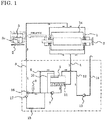
- FIG. 1 is a system diagram showing a seal oil supply device for rotating electric machine according to Embodiment 1 of the present invention, and also shows a rotating electric machine together.
- the rotating electric machine is, for example, a turbine generator of hydrogen-cooled type.
- the rotating electric machine 1 includes: a rotary shaft 2 penetrating a sealed chamber 1a in which hydrogen gas is sealed; and a seal ring 3 which is provided in each bearing chamber provided at both ends in the axial direction and which is a shaft sealing portion for sealing the gap between the sealed chamber 1a and the rotary shaft 2 of the rotating electric machine 1, using seal oil.
- Seal oil discharged from the seal ring 3 is sent via a seal oil discharge tube 4 to a vacuum tank 5 for vacuum-deaerating the seal oil.
- the upstream side of the seal ring 3 and the vacuum tank 5 are connected to each other via a seal oil supply tube 6 for supplying seal oil to the seal ring 3.
- a seal oil pump 7 for supplying seal oil stored in the vacuum tank 5 to the seal ring 3, and a differential pressure regulation valve 8 for regulating the pressure of the seal oil supplied to the seal ring 3, are attached to the seal oil supply tube 6.
- the differential pressure regulation valve 8 allows passage of the seal oil controlled to have a pressure higher by a certain value than the hydrogen gas pressure inside the rotating electric machine 1.
- seal oil return tube 9 for returning, to the vacuum tank 5, the seal oil that cannot pass through the differential pressure regulation valve 8, is connected to the seal oil supply tube 6 between the seal oil pump 7 and the differential pressure regulation valve 8.
- the other end side of the seal oil return tube 9 leads into the vacuum tank 5 and is connected to an ejection nozzle.
- An oil level regulation valve 11 for keeping the level of the seal oil constant is attached to the vacuum tank 5.
- the vacuum tank 5 is provided with a gas discharge tube 12 for discharging gas containing air, an oil component, moisture, hydrogen, etc., and the gas discharge tube 12 is connected to a vacuum pump 13.
- the gas is discharged from the vacuum pump 13 via an ejection tube 14 to the outside.
- a relief valve 15 having a setting pressure of, for example, 0.1 to 0.2 MPa-g is provided in parallel with the differential pressure regulation valve 8.
- a first route for supplying the seal oil from the seal oil pump 7 via the differential pressure regulation valve 8 is formed, and in addition, a second route for supplying the seal oil from the seal oil pump 7 via the relief valve 15 is formed.
- One end side of a seal oil return tube 10 for returning, to the vacuum tank 5, the seal oil that cannot pass through the relief valve 15, is connected between the seal oil pump 7 and the relief valve 15.
- Check valves 16 and 17 are provided on the downstream side of the differential pressure regulation valve 8 and the downstream side of the relief valve 15, respectively.
- seal oil is supplied from the seal oil supply tube 6 via an oil supply hole 3a, to form an oil film between the seal ring 3 and the rotary shaft 2, thereby preventing hydrogen gas sealed in the rotating electric machine 1 from leaking to the outside.
- the hydrogen gas in the rotating electric machine 1 is sealed by the seal oil which circulates through the seal oil supply circuit connected to the seal ring 3 as shown in FIG. 1 .
- the seal oil is fed by the seal oil pump 7 and is regulated by the differential pressure regulation valve 8 so as to have a pressure higher by a certain value than that of the hydrogen gas in the rotating electric machine 1.
- the regulated seal oil passes through the seal oil supply tube 6 and is sent to the seal ring 3. At the seal ring 3, the seal oil is exposed to the outside air to contain air, moisture, hydrogen gas, etc..
- the seal oil is retrieved to the vacuum tank 5 through the seal oil discharge tube 4, and vacuum-deaerated in the vacuum tank 5.
- the deaeration air obtained by deaeration in the vacuum tank 5 is sent through the gas discharge tube 12 to the vacuum pump 13, and then ejected through the ejection tube 14 to the outside.
- seal oil that passes through the first route from the seal oil pump 7 via the differential pressure regulation valve 8 is regulated by the differential pressure regulation valve 8 so that the pressure of the seal oil becomes gas pressure + differential pressure (about 0.05 to 0.10 MPa-g), and then the seal oil is supplied to the seal ring 3 through the oil supply tube 6.
- seal oil is supplied through the second route from the seal oil pump 7 via the relief valve 15, and since the setting pressure (0.1 to 0.2 MPa-g) of the relief valve 15 in the second route is greater than the pressure (machine-inside gas pressure + differential pressure) regulated by the differential pressure regulation valve 8 in the first route, the oil having the setting pressure of the relief valve 15 is supplied to the seal ring 3.
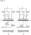
- FIG. 2 is a diagram illustrating a pressure distribution around the seal ring 3 in Embodiment 1, in which (a) shows the pressure gradient of seal oil when the gas pressure is 0.30 MPa-g, and (b) shows the pressure gradient of seal oil when the gas pressure is 0.00 MPa-g.
- FIG. 3 is a diagram illustrating a pressure distribution around the seal ring 3 in a conventional apparatus, in which (a) shows the pressure gradient of seal oil when the gas pressure is 0.30 MPa-g, and (b) shows the pressure gradient of seal oil when the gas pressure is 0.00 MPa-g.
- the machine-inner-side pressure gradient is the same as that in the case of gas pressure of 0.30 MPa-g, but the machine-outer-side pressure gradient is smaller than that in the case of gas pressure of 0.30 MPa-g.
- part enclosed by a dotted line between the rotary shaft 2 and the seal ring 3 indicates a region where an oil film is formed by the seal oil.
- seal oil is supplied from the seal oil pump 7 to the seal ring 3 of the rotating electric machine 1 in which hydrogen gas is sealed, via the differential pressure regulation valve 8 for regulating the pressure of the seal oil.
- the seal oil supply device for rotating electric machine has the first route for supplying the seal oil from the seal oil pump 7 via the differential pressure regulation valve 8, and in addition, has the second route for supplying the seal oil from the seal oil pump 7 via the relief valve 15.
- the gap between the rotary shaft 2 and the seal ring 3 during normal operation can be designed to be small, whereby oil amount reduction and size reduction can be achieved.
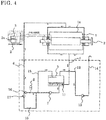
- the return oil from the differential pressure regulation valve 8 and the return oil from the relief valve 15 may be returned to the vacuum tank 5 through the same seal oil return tube 18.
Landscapes
- Engineering & Computer Science (AREA)
- General Engineering & Computer Science (AREA)
- Mechanical Engineering (AREA)
- Power Engineering (AREA)
- Motor Or Generator Cooling System (AREA)
- Sealing Using Fluids, Sealing Without Contact, And Removal Of Oil (AREA)
- Motor Or Generator Frames (AREA)
Claims (6)
- Dichtungsöl-Versorgungsvorrichtung für eine elektrische Rotationsmaschine, bei der Dichtungsöl von einer Dichtungsölpumpe (7) zu einem Dichtungsring (3) einer elektrischen Rotationsmaschine (1) zugeführt wird, in der Wasserstoffgas abgedichtet ist, und zwar über ein Differenzdruckregelventil zum Regulieren des Drucks des Dichtungsöls, wobei die Dichtungsöl-Versorgungsvorrichtung Folgendes aufweist:- einen ersten Pfad zum Zuführen des Dichtungsöls von der Dichtungsölpumpe (7) über das Differenzdruckregelventil (8) und- einen zweiten Pfad zum Zuführen des Dichtungsöls von der Dichtungsölpumpe (7) über ein Überdruckventil (15),dadurch gekennzeichnet,
dass die Dichtungsöl-Versorgungsvorrichtung ferner ein erstes Rückschlagventil (16), das auf der stromabwärtigen Seite des Differenzdruckregelventils (8) angeordnet ist, und ein zweites Rückschlagventil (17) aufweist, das auf der stromabwärtigen Seite des Überdruckventils (15) angeordnet ist. - Dichtungsöl-Versorgungsvorrichtung nach Anspruch 1,
wobei der Einstelldruck des Überdruckventils (15) auf einen Wert von 0,1 bis 0,2 MPa-g eingestellt ist. - Dichtungsöl-Versorgungsvorrichtung nach Anspruch 1 oder 2,
wobei der zweite Pfad parallel zu dem ersten Pfad ausgebildet ist, und
wobei bei dem ersten und dem zweiten Pfad jeweils Rückschlagventile (16, 17) vor einem Ort angeordnet sind, an dem der erste und der zweite Pfad zusammenlaufen. - Dichtungsöl-Versorgungsvorrichtung nach einem der Ansprüche 1 bis 3,
wobei Rücklauföl von dem Differenzdruckregelventil (8) und Rücklauföl von dem Überdruckventil (15) durch dasselbe Dichtungsöl-Rücklaufrohr (18) in einen Vakuumbehälter (5) zurückgeführt werden. - Dichtungsöl-Zuführungsverfahren für eine elektrische Rotationsmaschine, bei der Dichtungsöl von einer Dichtungsölpumpe (7) zu einem Dichtungsring (3) einer elektrischen Rotationsmaschine (1) zugeführt wird, in der Wasserstoffgas abgedichtet ist, und zwar über ein Differenzdruckregelventil (8) zum Regulieren des Drucks des Dichtungsöls, wobei das Dichtungsöl-Zuführungsverfahren folgende Schritte aufweist:- Zuführen des Dichtungsöls mittels eines ersten Pfads von der Dichtungsölpumpe (7) über das Differenzdruckregelventil (8) und ein erstes Rückschlagventil (16), das auf der stromabwärtigen Seite des Differenzdruckregelventils (8) angeordnet ist, während des normalen Betriebs der rotierenden elektrischen Maschine (1);
und- Zuführen des Dichtungsöls mittels eines zweiten Pfads von der Dichtungsölpumpe (7) über ein Überdruckventil (15) und ein zweites Rückschlagventil (17), das auf der stromabwärtigen Seite des Überdruckventils (15) angeordnet ist, wenn die elektrische Rotationsmaschine (1) mit einem Druck des Wasserstoffgases betrieben wird, der ein extrem niedriger Druck nahe 0,00 MPa-g ist. - Dichtungsöl-Zuführungsverfahren für eine elektrische Rotationsmaschine nach Anspruch 5,
wobei der Einstelldruck des Überdruckventils (15) auf einen Wert von 0,1 bis 0,2 MPa-g eingestellt ist.
Applications Claiming Priority (1)
| Application Number | Priority Date | Filing Date | Title |
|---|---|---|---|
| PCT/JP2014/064936 WO2015186221A1 (ja) | 2014-06-05 | 2014-06-05 | 回転電機の密封油供給装置及び密封油供給方法 |
Publications (3)
| Publication Number | Publication Date |
|---|---|
| EP3154163A1 EP3154163A1 (de) | 2017-04-12 |
| EP3154163A4 EP3154163A4 (de) | 2018-01-10 |
| EP3154163B1 true EP3154163B1 (de) | 2020-02-19 |
Family
ID=54766317
Family Applications (1)
| Application Number | Title | Priority Date | Filing Date |
|---|---|---|---|
| EP14893972.1A Active EP3154163B1 (de) | 2014-06-05 | 2014-06-05 | Dichtungsölversorgungsvorrichtung für eine dynamoelektrische maschine und dichtungsölversorgungsverfahren |
Country Status (5)
| Country | Link |
|---|---|
| US (1) | US10069370B2 (de) |
| EP (1) | EP3154163B1 (de) |
| JP (1) | JP6139790B2 (de) |
| CN (1) | CN106416005B (de) |
| WO (1) | WO2015186221A1 (de) |
Families Citing this family (2)
| Publication number | Priority date | Publication date | Assignee | Title |
|---|---|---|---|---|
| CN107366749A (zh) * | 2017-08-28 | 2017-11-21 | 利辛县宝隆橡塑密封件有限责任公司 | 一种防尘密封 |
| CN112483357A (zh) * | 2020-11-11 | 2021-03-12 | 杭州国能汽轮工程有限公司 | 一种多功能供油系统 |
Family Cites Families (14)
| Publication number | Priority date | Publication date | Assignee | Title |
|---|---|---|---|---|
| US3176996A (en) * | 1962-10-12 | 1965-04-06 | Barnett Leon Truman | Oil balanced shaft seal |
| US4029323A (en) * | 1972-04-11 | 1977-06-14 | Nippon Seiko Kabushiki Kaisha | Fluid pressure seal arrangement |
| US4005580A (en) * | 1975-06-12 | 1977-02-01 | Swearingen Judson S | Seal system and method |
| US4058320A (en) * | 1976-07-26 | 1977-11-15 | Westinghouse Electric Corporation | Generator seal oil supply system |
| JPS58148641A (ja) | 1982-02-26 | 1983-09-03 | Toshiba Corp | タ−ビン発電機の軸封油供給装置 |
| JPS62145462U (de) | 1986-03-10 | 1987-09-14 | ||
| JPS6445472U (de) * | 1987-09-11 | 1989-03-20 | ||
| US4969796A (en) | 1989-10-30 | 1990-11-13 | Westinghouse Electric Corp. | Method and apparatus for cooling shaft seals |
| US5474304A (en) * | 1994-06-27 | 1995-12-12 | General Electric Co. | Seal oil supply system using differential pressure accumulator |
| JPH0965600A (ja) | 1995-08-28 | 1997-03-07 | Toshiba Corp | 回転電機の軸密封油系統のフロートトラップ槽 |
| US6116609A (en) * | 1997-12-17 | 2000-09-12 | A. W. Chesterton Company | Fluidic feedback pressure regulation system for a mechanical seal |
| JP2001028867A (ja) | 1999-07-13 | 2001-01-30 | Mitsubishi Electric Corp | 回転電機の軸シール装置 |
| JP2004007876A (ja) * | 2002-05-31 | 2004-01-08 | Mitsubishi Electric Corp | 回転電機の密封油供給装置 |
| JP4437752B2 (ja) * | 2005-02-16 | 2010-03-24 | 三菱電機株式会社 | 回転電機の密封油供給装置 |
-
2014
- 2014-06-05 EP EP14893972.1A patent/EP3154163B1/de active Active
- 2014-06-05 WO PCT/JP2014/064936 patent/WO2015186221A1/ja not_active Ceased
- 2014-06-05 US US15/303,701 patent/US10069370B2/en not_active Expired - Fee Related
- 2014-06-05 JP JP2016525629A patent/JP6139790B2/ja not_active Expired - Fee Related
- 2014-06-05 CN CN201480079581.0A patent/CN106416005B/zh not_active Expired - Fee Related
Non-Patent Citations (1)
| Title |
|---|
| None * |
Also Published As
| Publication number | Publication date |
|---|---|
| JP6139790B2 (ja) | 2017-05-31 |
| WO2015186221A1 (ja) | 2015-12-10 |
| CN106416005B (zh) | 2019-02-15 |
| EP3154163A1 (de) | 2017-04-12 |
| US20170040862A1 (en) | 2017-02-09 |
| EP3154163A4 (de) | 2018-01-10 |
| US10069370B2 (en) | 2018-09-04 |
| JPWO2015186221A1 (ja) | 2017-04-20 |
| CN106416005A (zh) | 2017-02-15 |
Similar Documents
| Publication | Publication Date | Title |
|---|---|---|
| US10396618B2 (en) | Rotating electric machine with shaft-seal devices having partition plate | |
| US10208611B2 (en) | Flanged spring guide for a face seal arrangement | |
| US9429037B2 (en) | Turbine including seal air valve system | |
| EP3141759B1 (de) | Turbopumpe | |
| AU2016280924B2 (en) | Expansion turbine device | |
| US10364691B2 (en) | Turbomachine comprising a ventilation system | |
| US10069370B2 (en) | Seal oil supply device for dynamo-electric machine and seal oil supply method | |
| US10396630B2 (en) | System and method for cooling windings of generator rotor | |
| US20170191486A1 (en) | Fluid energy machine having a tandem dry gas seal | |
| US20100247285A1 (en) | Systems and Methods for Providing Compressor Extraction Cooling | |
| AU2016280925B2 (en) | Expansion turbine device | |
| EP2189688A1 (de) | Schaftabdichtsystem, insbesondere für einen wasserstoffgekühlten Generator | |
| US20160341429A1 (en) | Gas turbine engine liquid fuel supply system and method | |
| JP6205419B2 (ja) | 冷却方法 | |
| EP3427803B1 (de) | Rotierende elektrische maschine mit wellendichtungsvorrichtung | |
| US2968499A (en) | Shaft seal for hydrogen-cooled generator | |
| US10947864B2 (en) | Gas turbine with separate cooling for turbine and exhaust casing | |
| US9625101B2 (en) | Pressure controlled chamber | |
| GB2483714A (en) | Gas turbine engine bearing housing sealing | |
| US20210048026A1 (en) | Machine for aircraft and method | |
| KR20170073274A (ko) | 보일러 급수 펌프 |
Legal Events
| Date | Code | Title | Description |
|---|---|---|---|
| STAA | Information on the status of an ep patent application or granted ep patent |
Free format text: STATUS: THE INTERNATIONAL PUBLICATION HAS BEEN MADE |
|
| PUAI | Public reference made under article 153(3) epc to a published international application that has entered the european phase |
Free format text: ORIGINAL CODE: 0009012 |
|
| STAA | Information on the status of an ep patent application or granted ep patent |
Free format text: STATUS: REQUEST FOR EXAMINATION WAS MADE |
|
| 17P | Request for examination filed |
Effective date: 20161129 |
|
| AK | Designated contracting states |
Kind code of ref document: A1 Designated state(s): AL AT BE BG CH CY CZ DE DK EE ES FI FR GB GR HR HU IE IS IT LI LT LU LV MC MK MT NL NO PL PT RO RS SE SI SK SM TR |
|
| AX | Request for extension of the european patent |
Extension state: BA ME |
|
| DAX | Request for extension of the european patent (deleted) | ||
| A4 | Supplementary search report drawn up and despatched |
Effective date: 20171212 |
|
| RIC1 | Information provided on ipc code assigned before grant |
Ipc: F16J 15/40 20060101ALI20171206BHEP Ipc: H02K 5/124 20060101AFI20171206BHEP |
|
| GRAP | Despatch of communication of intention to grant a patent |
Free format text: ORIGINAL CODE: EPIDOSNIGR1 |
|
| STAA | Information on the status of an ep patent application or granted ep patent |
Free format text: STATUS: GRANT OF PATENT IS INTENDED |
|
| INTG | Intention to grant announced |
Effective date: 20190417 |
|
| GRAJ | Information related to disapproval of communication of intention to grant by the applicant or resumption of examination proceedings by the epo deleted |
Free format text: ORIGINAL CODE: EPIDOSDIGR1 |
|
| STAA | Information on the status of an ep patent application or granted ep patent |
Free format text: STATUS: REQUEST FOR EXAMINATION WAS MADE |
|
| GRAP | Despatch of communication of intention to grant a patent |
Free format text: ORIGINAL CODE: EPIDOSNIGR1 |
|
| STAA | Information on the status of an ep patent application or granted ep patent |
Free format text: STATUS: GRANT OF PATENT IS INTENDED |
|
| INTC | Intention to grant announced (deleted) | ||
| INTG | Intention to grant announced |
Effective date: 20190912 |
|
| GRAS | Grant fee paid |
Free format text: ORIGINAL CODE: EPIDOSNIGR3 |
|
| GRAA | (expected) grant |
Free format text: ORIGINAL CODE: 0009210 |
|
| STAA | Information on the status of an ep patent application or granted ep patent |
Free format text: STATUS: THE PATENT HAS BEEN GRANTED |
|
| AK | Designated contracting states |
Kind code of ref document: B1 Designated state(s): AL AT BE BG CH CY CZ DE DK EE ES FI FR GB GR HR HU IE IS IT LI LT LU LV MC MK MT NL NO PL PT RO RS SE SI SK SM TR |
|
| REG | Reference to a national code |
Ref country code: CH Ref legal event code: EP |
|
| REG | Reference to a national code |
Ref country code: DE Ref legal event code: R096 Ref document number: 602014061374 Country of ref document: DE |
|
| REG | Reference to a national code |
Ref country code: CH Ref legal event code: NV Representative=s name: VALIPAT S.A. C/O BOVARD SA NEUCHATEL, CH |
|
| REG | Reference to a national code |
Ref country code: AT Ref legal event code: REF Ref document number: 1236078 Country of ref document: AT Kind code of ref document: T Effective date: 20200315 |
|
| REG | Reference to a national code |
Ref country code: IE Ref legal event code: FG4D |
|
| REG | Reference to a national code |
Ref country code: NL Ref legal event code: MP Effective date: 20200219 |
|
| PG25 | Lapsed in a contracting state [announced via postgrant information from national office to epo] |
Ref country code: RS Free format text: LAPSE BECAUSE OF FAILURE TO SUBMIT A TRANSLATION OF THE DESCRIPTION OR TO PAY THE FEE WITHIN THE PRESCRIBED TIME-LIMIT Effective date: 20200219 Ref country code: NO Free format text: LAPSE BECAUSE OF FAILURE TO SUBMIT A TRANSLATION OF THE DESCRIPTION OR TO PAY THE FEE WITHIN THE PRESCRIBED TIME-LIMIT Effective date: 20200519 Ref country code: FI Free format text: LAPSE BECAUSE OF FAILURE TO SUBMIT A TRANSLATION OF THE DESCRIPTION OR TO PAY THE FEE WITHIN THE PRESCRIBED TIME-LIMIT Effective date: 20200219 |
|
| REG | Reference to a national code |
Ref country code: LT Ref legal event code: MG4D |
|
| PG25 | Lapsed in a contracting state [announced via postgrant information from national office to epo] |
Ref country code: LV Free format text: LAPSE BECAUSE OF FAILURE TO SUBMIT A TRANSLATION OF THE DESCRIPTION OR TO PAY THE FEE WITHIN THE PRESCRIBED TIME-LIMIT Effective date: 20200219 Ref country code: SE Free format text: LAPSE BECAUSE OF FAILURE TO SUBMIT A TRANSLATION OF THE DESCRIPTION OR TO PAY THE FEE WITHIN THE PRESCRIBED TIME-LIMIT Effective date: 20200219 Ref country code: HR Free format text: LAPSE BECAUSE OF FAILURE TO SUBMIT A TRANSLATION OF THE DESCRIPTION OR TO PAY THE FEE WITHIN THE PRESCRIBED TIME-LIMIT Effective date: 20200219 Ref country code: IS Free format text: LAPSE BECAUSE OF FAILURE TO SUBMIT A TRANSLATION OF THE DESCRIPTION OR TO PAY THE FEE WITHIN THE PRESCRIBED TIME-LIMIT Effective date: 20200619 Ref country code: BG Free format text: LAPSE BECAUSE OF FAILURE TO SUBMIT A TRANSLATION OF THE DESCRIPTION OR TO PAY THE FEE WITHIN THE PRESCRIBED TIME-LIMIT Effective date: 20200519 Ref country code: GR Free format text: LAPSE BECAUSE OF FAILURE TO SUBMIT A TRANSLATION OF THE DESCRIPTION OR TO PAY THE FEE WITHIN THE PRESCRIBED TIME-LIMIT Effective date: 20200520 |
|
| PG25 | Lapsed in a contracting state [announced via postgrant information from national office to epo] |
Ref country code: NL Free format text: LAPSE BECAUSE OF FAILURE TO SUBMIT A TRANSLATION OF THE DESCRIPTION OR TO PAY THE FEE WITHIN THE PRESCRIBED TIME-LIMIT Effective date: 20200219 |
|
| PG25 | Lapsed in a contracting state [announced via postgrant information from national office to epo] |
Ref country code: SK Free format text: LAPSE BECAUSE OF FAILURE TO SUBMIT A TRANSLATION OF THE DESCRIPTION OR TO PAY THE FEE WITHIN THE PRESCRIBED TIME-LIMIT Effective date: 20200219 Ref country code: PT Free format text: LAPSE BECAUSE OF FAILURE TO SUBMIT A TRANSLATION OF THE DESCRIPTION OR TO PAY THE FEE WITHIN THE PRESCRIBED TIME-LIMIT Effective date: 20200712 Ref country code: RO Free format text: LAPSE BECAUSE OF FAILURE TO SUBMIT A TRANSLATION OF THE DESCRIPTION OR TO PAY THE FEE WITHIN THE PRESCRIBED TIME-LIMIT Effective date: 20200219 Ref country code: CZ Free format text: LAPSE BECAUSE OF FAILURE TO SUBMIT A TRANSLATION OF THE DESCRIPTION OR TO PAY THE FEE WITHIN THE PRESCRIBED TIME-LIMIT Effective date: 20200219 Ref country code: LT Free format text: LAPSE BECAUSE OF FAILURE TO SUBMIT A TRANSLATION OF THE DESCRIPTION OR TO PAY THE FEE WITHIN THE PRESCRIBED TIME-LIMIT Effective date: 20200219 Ref country code: DK Free format text: LAPSE BECAUSE OF FAILURE TO SUBMIT A TRANSLATION OF THE DESCRIPTION OR TO PAY THE FEE WITHIN THE PRESCRIBED TIME-LIMIT Effective date: 20200219 Ref country code: ES Free format text: LAPSE BECAUSE OF FAILURE TO SUBMIT A TRANSLATION OF THE DESCRIPTION OR TO PAY THE FEE WITHIN THE PRESCRIBED TIME-LIMIT Effective date: 20200219 Ref country code: SM Free format text: LAPSE BECAUSE OF FAILURE TO SUBMIT A TRANSLATION OF THE DESCRIPTION OR TO PAY THE FEE WITHIN THE PRESCRIBED TIME-LIMIT Effective date: 20200219 Ref country code: EE Free format text: LAPSE BECAUSE OF FAILURE TO SUBMIT A TRANSLATION OF THE DESCRIPTION OR TO PAY THE FEE WITHIN THE PRESCRIBED TIME-LIMIT Effective date: 20200219 |
|
| REG | Reference to a national code |
Ref country code: AT Ref legal event code: MK05 Ref document number: 1236078 Country of ref document: AT Kind code of ref document: T Effective date: 20200219 |
|
| REG | Reference to a national code |
Ref country code: DE Ref legal event code: R097 Ref document number: 602014061374 Country of ref document: DE |
|
| PLBE | No opposition filed within time limit |
Free format text: ORIGINAL CODE: 0009261 |
|
| STAA | Information on the status of an ep patent application or granted ep patent |
Free format text: STATUS: NO OPPOSITION FILED WITHIN TIME LIMIT |
|
| 26N | No opposition filed |
Effective date: 20201120 |
|
| PG25 | Lapsed in a contracting state [announced via postgrant information from national office to epo] |
Ref country code: MC Free format text: LAPSE BECAUSE OF FAILURE TO SUBMIT A TRANSLATION OF THE DESCRIPTION OR TO PAY THE FEE WITHIN THE PRESCRIBED TIME-LIMIT Effective date: 20200219 Ref country code: IT Free format text: LAPSE BECAUSE OF FAILURE TO SUBMIT A TRANSLATION OF THE DESCRIPTION OR TO PAY THE FEE WITHIN THE PRESCRIBED TIME-LIMIT Effective date: 20200219 Ref country code: AT Free format text: LAPSE BECAUSE OF FAILURE TO SUBMIT A TRANSLATION OF THE DESCRIPTION OR TO PAY THE FEE WITHIN THE PRESCRIBED TIME-LIMIT Effective date: 20200219 |
|
| PG25 | Lapsed in a contracting state [announced via postgrant information from national office to epo] |
Ref country code: SI Free format text: LAPSE BECAUSE OF FAILURE TO SUBMIT A TRANSLATION OF THE DESCRIPTION OR TO PAY THE FEE WITHIN THE PRESCRIBED TIME-LIMIT Effective date: 20200219 Ref country code: PL Free format text: LAPSE BECAUSE OF FAILURE TO SUBMIT A TRANSLATION OF THE DESCRIPTION OR TO PAY THE FEE WITHIN THE PRESCRIBED TIME-LIMIT Effective date: 20200219 |
|
| GBPC | Gb: european patent ceased through non-payment of renewal fee |
Effective date: 20200605 |
|
| PG25 | Lapsed in a contracting state [announced via postgrant information from national office to epo] |
Ref country code: LU Free format text: LAPSE BECAUSE OF NON-PAYMENT OF DUE FEES Effective date: 20200605 |
|
| REG | Reference to a national code |
Ref country code: BE Ref legal event code: MM Effective date: 20200630 |
|
| PG25 | Lapsed in a contracting state [announced via postgrant information from national office to epo] |
Ref country code: IE Free format text: LAPSE BECAUSE OF NON-PAYMENT OF DUE FEES Effective date: 20200605 Ref country code: GB Free format text: LAPSE BECAUSE OF NON-PAYMENT OF DUE FEES Effective date: 20200605 Ref country code: FR Free format text: LAPSE BECAUSE OF NON-PAYMENT OF DUE FEES Effective date: 20200630 |
|
| PG25 | Lapsed in a contracting state [announced via postgrant information from national office to epo] |
Ref country code: BE Free format text: LAPSE BECAUSE OF NON-PAYMENT OF DUE FEES Effective date: 20200630 |
|
| PG25 | Lapsed in a contracting state [announced via postgrant information from national office to epo] |
Ref country code: TR Free format text: LAPSE BECAUSE OF FAILURE TO SUBMIT A TRANSLATION OF THE DESCRIPTION OR TO PAY THE FEE WITHIN THE PRESCRIBED TIME-LIMIT Effective date: 20200219 Ref country code: MT Free format text: LAPSE BECAUSE OF FAILURE TO SUBMIT A TRANSLATION OF THE DESCRIPTION OR TO PAY THE FEE WITHIN THE PRESCRIBED TIME-LIMIT Effective date: 20200219 Ref country code: CY Free format text: LAPSE BECAUSE OF FAILURE TO SUBMIT A TRANSLATION OF THE DESCRIPTION OR TO PAY THE FEE WITHIN THE PRESCRIBED TIME-LIMIT Effective date: 20200219 |
|
| PG25 | Lapsed in a contracting state [announced via postgrant information from national office to epo] |
Ref country code: MK Free format text: LAPSE BECAUSE OF FAILURE TO SUBMIT A TRANSLATION OF THE DESCRIPTION OR TO PAY THE FEE WITHIN THE PRESCRIBED TIME-LIMIT Effective date: 20200219 Ref country code: AL Free format text: LAPSE BECAUSE OF FAILURE TO SUBMIT A TRANSLATION OF THE DESCRIPTION OR TO PAY THE FEE WITHIN THE PRESCRIBED TIME-LIMIT Effective date: 20200219 |
|
| PGFP | Annual fee paid to national office [announced via postgrant information from national office to epo] |
Ref country code: DE Payment date: 20220505 Year of fee payment: 9 |
|
| PGFP | Annual fee paid to national office [announced via postgrant information from national office to epo] |
Ref country code: CH Payment date: 20220702 Year of fee payment: 9 |
|
| REG | Reference to a national code |
Ref country code: DE Ref legal event code: R119 Ref document number: 602014061374 Country of ref document: DE |
|
| REG | Reference to a national code |
Ref country code: CH Ref legal event code: PL |
|
| PG25 | Lapsed in a contracting state [announced via postgrant information from national office to epo] |
Ref country code: DE Free format text: LAPSE BECAUSE OF NON-PAYMENT OF DUE FEES Effective date: 20240103 Ref country code: CH Free format text: LAPSE BECAUSE OF NON-PAYMENT OF DUE FEES Effective date: 20230630 |