EP3153885B1 - Opto-electronic protective device - Google Patents
Opto-electronic protective device Download PDFInfo
- Publication number
- EP3153885B1 EP3153885B1 EP15189223.9A EP15189223A EP3153885B1 EP 3153885 B1 EP3153885 B1 EP 3153885B1 EP 15189223 A EP15189223 A EP 15189223A EP 3153885 B1 EP3153885 B1 EP 3153885B1
- Authority
- EP
- European Patent Office
- Prior art keywords
- protected
- light
- zones
- protected zone
- release
- Prior art date
- Legal status (The legal status is an assumption and is not a legal conclusion. Google has not performed a legal analysis and makes no representation as to the accuracy of the status listed.)
- Active
Links
- 230000001681 protective effect Effects 0.000 title claims description 29
- 230000005693 optoelectronics Effects 0.000 title claims description 10
- 238000011156 evaluation Methods 0.000 claims description 12
- 238000012544 monitoring process Methods 0.000 claims description 7
- 238000000034 method Methods 0.000 claims description 6
- 230000003287 optical effect Effects 0.000 claims description 4
- 230000005540 biological transmission Effects 0.000 claims 3
- 238000009434 installation Methods 0.000 description 5
- 241000196324 Embryophyta Species 0.000 description 4
- 238000011161 development Methods 0.000 description 3
- 238000001514 detection method Methods 0.000 description 2
- 231100001261 hazardous Toxicity 0.000 description 2
- 238000012545 processing Methods 0.000 description 2
- 241000183024 Populus tremula Species 0.000 description 1
- 238000013459 approach Methods 0.000 description 1
- 230000004888 barrier function Effects 0.000 description 1
- 230000009194 climbing Effects 0.000 description 1
- 238000004519 manufacturing process Methods 0.000 description 1
- 238000003825 pressing Methods 0.000 description 1
- 238000003466 welding Methods 0.000 description 1
Images


Classifications
-
- G—PHYSICS
- G01—MEASURING; TESTING
- G01S—RADIO DIRECTION-FINDING; RADIO NAVIGATION; DETERMINING DISTANCE OR VELOCITY BY USE OF RADIO WAVES; LOCATING OR PRESENCE-DETECTING BY USE OF THE REFLECTION OR RERADIATION OF RADIO WAVES; ANALOGOUS ARRANGEMENTS USING OTHER WAVES
- G01S17/00—Systems using the reflection or reradiation of electromagnetic waves other than radio waves, e.g. lidar systems
- G01S17/02—Systems using the reflection of electromagnetic waves other than radio waves
- G01S17/06—Systems determining position data of a target
- G01S17/42—Simultaneous measurement of distance and other co-ordinates
-
- B—PERFORMING OPERATIONS; TRANSPORTING
- B25—HAND TOOLS; PORTABLE POWER-DRIVEN TOOLS; MANIPULATORS
- B25J—MANIPULATORS; CHAMBERS PROVIDED WITH MANIPULATION DEVICES
- B25J9/00—Programme-controlled manipulators
- B25J9/16—Programme controls
- B25J9/1674—Programme controls characterised by safety, monitoring, diagnostic
- B25J9/1676—Avoiding collision or forbidden zones
-
- G—PHYSICS
- G01—MEASURING; TESTING
- G01S—RADIO DIRECTION-FINDING; RADIO NAVIGATION; DETERMINING DISTANCE OR VELOCITY BY USE OF RADIO WAVES; LOCATING OR PRESENCE-DETECTING BY USE OF THE REFLECTION OR RERADIATION OF RADIO WAVES; ANALOGOUS ARRANGEMENTS USING OTHER WAVES
- G01S17/00—Systems using the reflection or reradiation of electromagnetic waves other than radio waves, e.g. lidar systems
- G01S17/02—Systems using the reflection of electromagnetic waves other than radio waves
- G01S17/04—Systems determining the presence of a target
-
- G—PHYSICS
- G05—CONTROLLING; REGULATING
- G05B—CONTROL OR REGULATING SYSTEMS IN GENERAL; FUNCTIONAL ELEMENTS OF SUCH SYSTEMS; MONITORING OR TESTING ARRANGEMENTS FOR SUCH SYSTEMS OR ELEMENTS
- G05B19/00—Programme-control systems
- G05B19/02—Programme-control systems electric
- G05B19/18—Numerical control [NC], i.e. automatically operating machines, in particular machine tools, e.g. in a manufacturing environment, so as to execute positioning, movement or co-ordinated operations by means of programme data in numerical form
- G05B19/406—Numerical control [NC], i.e. automatically operating machines, in particular machine tools, e.g. in a manufacturing environment, so as to execute positioning, movement or co-ordinated operations by means of programme data in numerical form characterised by monitoring or safety
- G05B19/4061—Avoiding collision or forbidden zones
-
- G—PHYSICS
- G05—CONTROLLING; REGULATING
- G05B—CONTROL OR REGULATING SYSTEMS IN GENERAL; FUNCTIONAL ELEMENTS OF SUCH SYSTEMS; MONITORING OR TESTING ARRANGEMENTS FOR SUCH SYSTEMS OR ELEMENTS
- G05B2219/00—Program-control systems
- G05B2219/30—Nc systems
- G05B2219/37—Measurements
- G05B2219/37275—Laser, interferometer
-
- G—PHYSICS
- G05—CONTROLLING; REGULATING
- G05B—CONTROL OR REGULATING SYSTEMS IN GENERAL; FUNCTIONAL ELEMENTS OF SUCH SYSTEMS; MONITORING OR TESTING ARRANGEMENTS FOR SUCH SYSTEMS OR ELEMENTS
- G05B2219/00—Program-control systems
- G05B2219/30—Nc systems
- G05B2219/37—Measurements
- G05B2219/37631—Means detecting object in forbidden zone
Description
Die Erfindung betrifft eine optoelektronische Schutzeinrichtung nach dem Oberbegriff des Anspruchs 1.The invention relates to an optoelectronic protective device according to the preamble of claim 1.
Solche Schutzeinrichtungen werden zum Beispiel an Anlagen wie Pressen, Stanzen, Schweißrobotern und dergleichen eingesetzt, bei denen ein Gefahrenbereich, z.B. ein Zugangsbereich, überwacht werden muss, der beim Betrieb der Maschine von einer Bedienperson nicht betreten werden darf. Wird mit Hilfe der Schutzeinrichtung die Anwesenheit eines unzulässigen Gegenstands - also zum Beispiel ein Bein einer Bedienperson - im Gefahrenbereich festgestellt, werden alle gefahrbringenden Bewegungen gestoppt. Nach diesem Stopp sind bewusste Aktionen erforderlich, um die Anlage in Gang zu setzen. Hierzu zählt das manuelle Rücksetzen der Schutzeinrichtung zum Vorbereiten des Wiederanlaufs der Anlage.Such guards are used, for example, on equipment such as presses, punches, welding robots and the like where a danger area, e.g. an access area must be monitored, which must not be entered by an operator during operation of the machine. If the presence of an inadmissible object - for example a leg of an operator - in the danger zone is detected with the aid of the protective device, all dangerous movements are stopped. After this stop, conscious actions are required to start the system. This includes the manual reset of the protective device to prepare the restart of the system.
Häufig werden als optoelektronische Schutzeinrichtung Sicherheitslaserscanner eingesetzt, wie sie beispielsweise aus der
Derartige Schutzeinrichtungen müssen zuverlässig arbeiten und deshalb hohe Sicherheitsanforderungen, beispielsweise die Norm EN13849 für Maschinensicherheit und die Gerätenorm EN61496 für berührungslos wirkende Schutzeinrichtungen (BWS), erfüllen.Such protective devices must work reliably and therefore meet high safety requirements, for example the standard EN13849 for machine safety and the device standard EN61496 for non-contact protective devices (ESPE).
Einige der so überwachten Bereiche, z.B. ein Zugangsbereich, werden z.B. von Bedienpersonen häufiger oder sogar regelmäßig betreten, um z.B. Material zu der Anlage zuzuführen. Die Sicherheitsnorm schreibt es dann vor, dass die Anlage nur dann automatisch selbsttätig wieder anfahren kann, wenn sichergestellt ist, dass eine gefährliche Situation nicht existieren kann ("only if a hazardous situation cannot exist"). Das kann aber durch automatische Schutzeinrichtungen fast nie sichergestellt werden, denn diese können nicht jeden freien Winkel einer abzusichernden Anlage erfassen. So ist es immer möglich, dass eine Person zwar die Schutzbereiche der Schutzeinrichtung nicht mehr verletzt, aber sich dennoch im Gefahrenbereich einer Anlage befindet, z.B. durch Klettern auf ein Anlagenteil oder sonstiges "Verstecken" in der Maschine. Die Forderung der Sicherheitsnorm wird dann dadurch erfüllt, dass die Anlage manuell anzufahren ist durch manuelles Betätigen einer Rücksetzeinrichtung (Reset-Taster) und darauffolgendes manuelles Betätigen eines Restart--Tasters. Das ist jedes Mal aufwändig.Some of the areas monitored in this way, eg an access area, are entered by operators more frequently or even regularly, for example, to feed material to the installation. The safety standard then stipulates that the system can automatically restart automatically if it is ensured that a dangerous situation can not exist ("only if a hazardous situation can not exist"). However, this can almost never be ensured by automatic safety devices, because they can not detect every free angle of a system to be protected. So it is always possible that a person no longer violates the protective areas of the protective device, but is still in the danger zone of a system, for example by climbing on a part of the system or other "hiding" in the machine. The requirement of the safety standard is then met by the fact that the system is manually approach by manual operation a reset device (reset button) and then manually pressing a restart button. This is time consuming.
Aus der
Ausgehend von diesem Stand der Technik ist es Aufgabe der Erfindung, eine verbesserte Schutzeinrichtung und ein entsprechendes Überwachungsverfahren bereitzustellen, mit dem zwar die Sicherheit gewährleistet bleibt, aber der Wiederanlauf der Anlage vereinfacht ist.Based on this prior art, it is an object of the invention to provide an improved protective device and a corresponding monitoring method, with which although the security is guaranteed, but the restart of the system is simplified.
Diese Aufgabe wird gelöst, durch eine Einrichtung mit den Merkmalen des Anspruchs 1 und ein Verfahren mit den Merkmalen des Anspruchs 8.This object is achieved by a device having the features of claim 1 and a method having the features of claim 8.
Die erfindungsgemäße optoelektronische Schutzeinrichtung dient zur optischen Überwachung mehrerer Schutzbereiche auf Verletzung durch wenigstens ein Objekt und zur Steuerung einer abzusichernden Anlage. Sie weist wenigstens eine Lichtsendeeinheit, mit der Sendelicht in die Schutzbereiche ausgesendet wird, eine Lichtempfangseinheit, mit dem an dem Objekt reflektiertes Sendelicht empfangen wird und in elektrische Empfangssignale umgewandelt wird und eine Auswerteeinheit zur Auswertung der Empfangssignale auf, um festzustellen, welcher der Schutzbereiche durch das Objekt verletzt wird (Schutzbereichsverletzung) und welchen Schutzbereich das Objekt verlassen hat (Schutzbereichsfreigabe). Erfindungsgemäß ist eine Steuerung vorgesehen zur Erzeugung und Ausgabe eines Schaltsignals, das ein Freigabesignal zur Freigabe des Anlagenbetriebs ist und dass die Steuerung dazu ausgebildet ist, das Freigabesignal nur dann auszugeben, wenn die Steuerung eine vorbestimmte Reihenfolge von Ereignissen, bestehend aus Schutzbereichsverletzungen und Schutzbereichsfreigaben der verschiedenen Schutzbereiche, erkennt.The optoelectronic protective device according to the invention is used for optical monitoring of a plurality of protection zones for damage by at least one object and for controlling a system to be protected. It has at least one light-emitting unit with which transmitted light is emitted into the protected areas, a light-receiving unit with which transmitted light reflected at the object is received and converted into electrical received signals and an evaluation unit for evaluating the received signals to determine which of the protected areas by the Object is violated (protection area violation) and which protection area the object has left (protection area release). According to the invention, a controller is provided for generating and outputting a switching signal, which is a release signal for enabling the plant operation and in that the controller is designed to output the release signal only if the controller has a predetermined sequence of events consisting of protection zone violations and protection zone releases of the various Protection areas, recognizes.
Der wesentliche Vorteil einer so ausgebildeten Schutzeinrichtung ist die Möglichkeit, dass die abzusichernde Anlage dann automatisch nach dem Freigabesignal wieder anlaufen kann. Die Schutzeinrichtung erfasst die mehreren Schutzbereiche und stellt fest, in welcher Reihenfolge diese verletzt werden und wieder freigegeben werden. Auf diese Weise kann ein Weg einer Person durch die Schutzbereiche auf einfache Weise verfolgt werden und zwar durch die an sich "dumme" Schutzeinrichtung, die im Prinzip nur feststellt, ob ein Schutzbereich verletzt ist oder nicht. Durch die zusätzliche, erfindungsgemäße Erfassung der Reihenfolge ist jetzt aber eine Möglichkeit geschaffen, diejenigen Situationen, in denen eine Person die Anlage betritt und wieder verlässt, von anderen Situationen, die potentiell Gefahr bergen, unterscheiden zu können. Dann kann sicher gesagt werden, dass die Person, die die Anlage betreten hat, diese auch wieder verlassen hat und das Merkmal der Norm "a hazardous situation cannot exist" erfüllt ist. Ein automatischer Wiederanlauf kann dann erfolgen. Das erspart Zeit, Aufwand und damit Produktionskosten. Die Produktivität ist erhöht.The main advantage of a protection device designed in this way is the possibility that the system to be protected can then restart automatically after the release signal. The protective device covers the several protection areas and Determines in which order these are violated and released again. In this way a way of a person through the protection areas can be pursued in a simple way and by the "stupid" Protective device, which in principle only determines whether a protected area is damaged or not. Due to the additional detection of the sequence according to the invention, however, it is now possible to be able to differentiate those situations in which a person enters and leaves the installation from other situations which are potentially dangerous. It can then be said with certainty that the person who entered the facility has also left it and that the characteristic of the standard "a hazardous situation can not exist" is met. An automatic restart can then take place. This saves time, effort and thus production costs. Productivity is increased.
Ebenso ist die Schutzeinrichtung besser vor Fehlgebrauch geschützt. So ist ein manueller Anlauf der Anlage keine Routinemaßnahme mehr, sondern eine außergewöhnliche Gefahrensituation, die wegen ihrer Besonderheit dann auch als solche besser erkannt und mit mehr Vorsicht behandelt wird. Das erhöht weiter die Sicherheit.Likewise, the guard is better protected against misuse. Thus, a manual start-up of the plant is no longer a routine measure, but an exceptional danger situation, which is recognized because of its special nature as such better and treated with more care. This further increases security.
In diesen besonderen Situationen, wenn also die Reihenfolge der Ereignisse (Schutzbereichsverletzungen - Schutzbereichsfreigaben) nicht eingehalten ist, ist der automatische Wiederanlauf gesperrt und die Anlage kann nur in bekannter Weise mit manuellem Reset und Restart wieder angefahren werden.In these special situations, ie if the sequence of events (protection zone violations - protection zone releases) is not adhered to, the automatic restart is blocked and the system can only be restarted in a known manner with manual reset and restart.
Um keine unüberwachten Lücken zwischen den Schutzbereichen entstehen zu lassen, ist es vorteilhaft, wenn die Schutzbereiche benachbart sind und bevorzugt lückenlos aneinandergrenzen oder sogar zumindest teilweise überlappen. Auch eine vollständige Überlappung der verschiedenen Schutzbereiche wäre möglich. Dann müssten sie aber zumindest unterschiedlich groß sein, so dass es örtliche Bereiche gibt, die eindeutig nur einem Schutzbereich zugeordnet sind.In order to prevent unmonitored gaps between the protection areas, it is advantageous if the protection areas are adjacent and preferably adjoin one another without gaps or even overlap at least partially. Even a complete overlap of the different protection areas would be possible. Then they would have to be at least different in size, so that there are local areas that are clearly assigned to only one protected area.
In Weiterbildung der Erfindung weist die Einrichtung einen Ausgang für ein Stopp-Signal auf, wobei die Steuerung ausgebildet ist, das Stopp-Signal zu erzeugen, wenn im Normalbetrieb der Anlage ein Schutzfeld verletzt wird. Die Schutzeinrichtung dient also nicht nur zum sicheren Steuern eines Wiederanlaufs, sondern wie bisher auch als Schutzeinrichtung für das Anhalten gefahrbringender Bewegungen.In a development of the invention, the device has an output for a stop signal, wherein the controller is designed to generate the stop signal if a protective field is violated during normal operation of the system. The protective device is therefore not only used to safely control a restart, but as before, as a protective device for stopping dangerous movements.
In Weiterbildung der Erfindung weist die Steuerung einen Zeitgeber auf, so dass die Auswerteeinheit überwachen kann, ob aufeinanderfolgende Ereignisse innerhalb bestimmter Zeitfenster erfolgen.In a further development of the invention, the controller has a timer, so that the evaluation unit can monitor whether successive events take place within specific time windows.
Zur Überwachung mehrerer Schutzbereiche, wie es für die Erfindung erforderlich ist, sollte die Einrichtung möglichst einfach ausgebildet sein. Deshalb weist in Weiterbildung der Erfindung die Lichtsendeeinheit nur einen Lichtsender auf und die Lichtempfangseinheit nur einen Lichtempfänger auf.To monitor multiple protection areas, as required for the invention, the device should be as simple as possible. Therefore, in a further development of the invention, the light-emitting unit has only one light transmitter and the light-receiving unit has only one light receiver.
Zur Überwachung mehrerer Schutzbereiche ist ein Laserscanner besonders geeignet, dessen einer Sendelichtstrahl die Schutzbereiche überstreicht. So kann mit nur einem Gerät die Überwachung erfolgen. Der Laserscanner könnte sogar auch die Steuerung beinhalten. Alternativ kann die Steuerung auch separat vorgesehen sein, an die der Laserscanner angeschlossen ist.For monitoring a plurality of protection areas, a laser scanner is particularly suitable, whose one transmitted light beam passes over the protection areas. This allows monitoring with just one device. The laser scanner could even include the controller. Alternatively, the controller may also be provided separately, to which the laser scanner is connected.
Wie oben erwähnt, wird die Aufgabe in analoger Weise auch durch ein Verfahren gelöst. Nach dem erfindungsgemäßen Verfahren werden mehrere Schutzbereiche auf Verletzung durch wenigstens ein Objekt optisch überwacht und eine abzusichernde Anlage gesteuert. Bei dem Verfahren wird
- Sendelicht von einer Lichtsendeeinheit in die Schutzbereiche ausgesandt,
- an dem Objekt reflektiertes Sendelicht mit einer Lichtempfangseinheit empfangen und in elektrische Empfangssignale umgewandelt,
- die Empfangssignale von einer Auswerteeinheit ausgewertet um festzustellen, welcher der Schutzbereiche durch das Objekt verletzt wird (Schutzbereichsverletzung) und welchen Schutzbereich das Objekt verlassen hat (Schutzfeldfreigabe)
- ein Schaltsignal, das ein Freigabesignal zur Freigabe des Anlagenbetriebs ist, in einer Steuerung erzeugt und von dieser ausgegeben
- und das Freigabesignal wird von der Steuerung nur dann ausgegeben, wenn die Steuerung eine vorbestimmte Reihenfolge von Ereignissen, bestehend aus Schutzbereichsverletzungen und Schutzbereichsfreigaben der verschiedenen Schutzbereiche, erkennt.
- Transmitted light from a light-emitting unit in the protection areas,
- receiving light reflected at the object is received by a light receiving unit and converted into received electrical signals,
- the receive signals are evaluated by an evaluation unit to determine which of the protection zones is violated by the object (protection zone violation) and which protection area the object has left (protective field release)
- a switching signal, which is a release signal for enabling the plant operation, generated in and output from a controller
- and the enable signal is output from the controller only if the controller has a predetermined sequence of events consisting of Protection zone violations and protection zone releases of the various protection zones.
Die Erfindung wird nachstehend auch hinsichtlich weiterer Vorteile und Merkmale unter Bezugnahme auf die beigefügte Zeichnung anhand von Ausführungsbeispielen erläutert. Die Figuren der Zeichnung zeigen in:
- Fig. 1
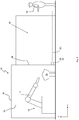
- eine schematische Darstellung einer abzusichernden Anlage mit einer erfindungsgemäßen Schutzeinrichtung in der Seitenansicht;
- Fig. 2
- eine schematische Darstellung der abzusichernden Anlage aus
Fig. 1 in der Draufsicht; - Fig. 3
- eine schematische Darstellung der optoelektronischen Schutzeinrichtung in einer Ausführungsform als Laserscanner.
- Fig. 1
- a schematic representation of a system to be protected with a protective device according to the invention in side view;
- Fig. 2
- a schematic representation of the system to be hedged
Fig. 1 in the plan view; - Fig. 3
- a schematic representation of the optoelectronic protective device in one embodiment as a laser scanner.
Eine in
Um dies zu verhindern, bestehen die Wände 22 der Roboterzelle 18 aus einem Gitter oder dergleichen. Ein Zugang 24 muss für Materialzu- und -abführung allerdings frei bleiben (
Der Zugangsbereich 26 ist zu seinen Seiten 26-1 und 26-2 hin durch mechanische Sperren 27, wie Zäune, abgesichert. Die der Roboterzelle 18 abgewandte Eingangsseite 26-3 ist offen, um Zugang zu erlauben. Die Fläche des Zugangsbereichs 26 ist durch eine erfindungsgemäße optoelektronische Schutzeinrichtung 28 abgesichert. Diese überwacht optisch in einem Überwachungsmodus, ob der Zugangsbereich 26 frei ist. Die optoelektronische Schutzeinrichtung 28 ist in diesem Ausführungsbeispiel als Sicherheits-Laserscanner 30 ausgebildet.
Diese Auswertung erfolgt in der Auswerteeinheit 50, die dafür mit der Lichtsendeeinheit 32, dem Lichtempfänger 42, dem Motor 44 und Encoder 48 verbunden ist. Mit den Winkel- und Entfernungsangaben lässt sich der Ort des Objektes 20 ermitteln und auf diese Weise der oder die Schutzbereiche SB vollständig überwachen. Die Schutzbereiche SB sind in ihren Abmessungen durch entsprechende Parameter definiert, die in der Auswerteeinheit 50 in einem Speicher 52 abgelegt sind. Befindet sich in einem der Schutzbereiche SB ein unzulässiges Objekt 20, so kann von der Auswerteeinheit 50 ein entsprechendes Objektfeststellungssignal ausgegeben werden und somit letztendlich ein Sicherheitssignal an einem Ausgang 54 des Laserscanners 30 ausgegeben werden, um zum Beispiel einen Stopp der Anlage 10 herbeizuführen oder diese zumindest in einen gefahrlosen Zustand zu versetzen.This evaluation takes place in the
Alle genannten Funktionskomponenten des Sicherheits-Laserscanners 30 sind in einem Gehäuse 58 angeordnet, das zumindest im Bereich der Lichtaus- und Lichteintritte eine zur Vermeidung von direkten Reflexionen in den Empfänger schräggestellte Frontscheibe 60 aufweist.All mentioned functional components of the
Tritt also während der Bearbeitung des Werkstücks 16 durch den Roboter 12 die Person in den Zugangsbereich 26 ein, erkennt dies die Schutzeinrichtung 28 und kann gegebenenfalls ein Schaltsignal ausgeben und einen Stopp des Roboters 12 oder zumindest ein Herunterfahren der Anlage 10 in einen gefahrlosen Zustand bewirken. Hat die Person 20 den überwachten Zugangsbereich 26 wieder verlassen, kann die Anlage 10 wieder anlaufen.If, during the processing of the
Wenn die Person 20 die Anlage betreten muss, um beispielsweise das Werkstück 16 herauszunehmen oder einzulegen, ist es erfindungsgemäß vorgesehen, dass die Anlage 10 selbsttätig, also automatisch wieder anläuft. Um für diesen Fall sicherzugehen, dass die Person 20 den Zugangsbereich 26 nach außen hin verlassen hat und beispielsweise den Zugangsbereich 26 nicht durch Eintritt in die Roboterzelle 18 nach Innen hin verlassen hat, ist die optoelektronische Schutzeinrichtung 28 nach der Erfindung speziell ausgebildet, was im Nachfolgenden insbesondere unter Bezugnahme auf
Der Zugangsbereich 26 wird im Wesentlichen vollständig, also vollflächig, von dem Scanbereich des Laserscanners 30 erfasst. Der so erfasste Zugangsbereich 26 ist aufgeteilt in mehrere, in diesem Beispiel vier, Schutzbereiche SB1 bis SB4, die aneinandergrenzen. Die Schutzbereiche SB1 bis SB4 liegen hintereinander aneinandergereiht von der Eingangsseite 26-3 bis zum Zugang 24. Die Person 20 wird also während des Zugangs zur Anlage 10 zunächst den ersten Schutzbereich SB1, dann SB2, dann SB3 und schließlich SB4 verletzen (Schutzbereichsverletzungen). Wenn die Person 20 die Anlage 10 wieder korrekt verlässt, tritt sie zunächst aus Schutzbereich SB4 aus (Schutzbereichsfreigabe), dann aus SB3, SB2 und schließlich wird Schutzbereich SB1 freigegeben.The
Die Schutzeinrichtung 28 weist eine Steuerung 56 auf, die diese Reihenfolge von Ereignissen, also die Reihenfolge von Schutzbereichsverletzungen und Schutzbereichsfreigaben, erfasst und auswertet. Entspricht die erfasste Reihenfolge einer vorbestimmten Reihenfolge, also zum Beispiel der zuvor genannten Schutzbereichsverletzungen von SB1 - SB2 - SB3 - SB4 und dann Schutzbereichsfreigaben von SB4 - SB3 - SB2 - SB1, dann erzeugt die Steuerung 56 ein Schaltsignal, das ein Freigabesignal zur Freigabe des Anlagenbetriebs ist. Dieses Freigabesignal wird an die Anlage ausgegeben.The
Die Steuerung 56 kann in die optoelektronische Schutzeinrichtung 28 integriert sein, wie in
Die vorbestimmten Reihenfolgen müssen nicht der oben beispielhaft beschriebenen entsprechen. Die beschriebene Reihenfolge ist aber die einfachste und bei Zugang einer Person durch einen Zugangsbereich wie in
Sinnvollerweise grenzen die Schutzbereiche aneinander ohne Lücken an, so dass es keine Lücken zwischen SB1 und SB2, zwischen SB2 und SB3 sowie zwischen SB3 und SB4 gibt. Die Schutzbereiche SB1 bis SB4 können auch überlappen.It makes sense that the protection areas adjoin one another without gaps, so there are no gaps between SB1 and SB2, between SB2 and SB3, and between SB3 and SB4. The protection areas SB1 to SB4 may also overlap.
Des Weiteren muss der Laserscanner 30 nicht zu jeder Zeit alle Schutzbereiche SB1 bis SB4 einsehen können. Wenn der Laserscanner 30 wie in
Sinnvollerweise weist die Steuerung 56 einen nicht dargestellten Zeitgeber auf, um überwachen zu können, dass die Ereignisse der Reihenfolge auch in einem tolerierbaren Zeitablauf stattfinden, um die Reihenfolge der Ereignisse möglichst eindeutig bestimmten realen Vorgänge sicher zuzuordnen.It makes sense for the
Claims (8)
- An optoelectronic protective device for the optical monitoring of a plurality of protected zones (SB1, SB2, SB3, SB4) for infringement by at least one object (20) and for controlling a plant (10) to be secured, comprising- a light transmission unit (32) with which transmitted light (34) is transmitted into the protected zones (SB1, SB2, SB3, SB4);- a light reception unit (42) with which transmitted light reflected at the object (20) (received light 38) is received and is converted into received electrical signals;- an evaluation unit (50) for evaluating the received signals to determine which of the protected zones (SB1, SB2, SB3, SB4) is infringed by the object (20), called a protected zone infringement in the following, and which protected zone (SB1, SB2, SB3, SB4) the object (20) has left, called a protected zone release in the following;- comprising a control (56) for generating and outputting a switching signal that is a release signal for the release of the plant operation,characterized in that
the control (56) is configured only to output the release signal when the control (56) recognizes a predefined sequence of events, with the events comprising protected zone infringements and protected zone releases of the protected zones (SB1, SB2, SB3, SB4) and with each event being either a protected zone infringement or a protected zone release. - A device in accordance with claim 1, characterized in that the protected zones (SB1, SB2, SB3, SB4) are adjacent to one another in a gapless manner.
- A device in accordance with one of the preceding claims, characterized in that the protected zones (SB1, SB2, SB3, SB4) at least partly overlap.
- A device in accordance with any one of the preceding claims, characterized in that the device has an output (54) for a stop signal, with the control being configured to generate the stop signal when a protected zone (SB1, SB2, SB3, SB4) is infringed and the predefined sequence is not run through.
- A device in accordance with any one of the preceding claims, characterized in that the control (56) has a clock so that the evaluation unit can monitor whether consecutive events take place within specific time windows.
- A device in accordance with any one of the preceding claims, characterized in that the light transmission unit (32) only has one light transmitter and the light reception unit (42) only has one light receiver.
- A device in accordance with any one of the preceding claims, characterized in that the device has a laser scanner (30) whose transmitted light sweeps over the protected zones (SB1, SB2, SB3, SB4).
- A method for the optical monitoring of a plurality of protected zones (SB1, SB2, SB3, SB4) for infringement by at least one object (20) and for controlling a plant (10) to be secured, in which- transmitted light (34) is transmitted from a light transmission unit (32) into the protected zones (SB1, SB2, SB3, SB4);- transmitted light (38) reflected at the object (20) is received by a light reception unit (42) and is converted into received electrical signals;- the received signals are evaluated by an evaluation unit (50) to determine which of the protected zones (SB1, SB2, SB3, SB4) is infringed by the object (20), called a protected zone infringement in the following, and which protected zone (SB1, SB2, SB3, SB4) the object (20) has left, called a protected zone release in the following,- wherein a switching signal that is a release signal for releasing the plant operation is generated in a control (56) and is output by it;- and the release signal is only output by the control (56) when the control (56) recognizes a predefined sequence of events, with the events comprising protected zone infringements and protected zone releases of the protected zones (SB1, SB2, SB3, SB4) and with each event being either a protected zone infringement or a protected zone release.
Priority Applications (2)
| Application Number | Priority Date | Filing Date | Title |
|---|---|---|---|
| EP15189223.9A EP3153885B1 (en) | 2015-10-09 | 2015-10-09 | Opto-electronic protective device |
| ES15189223.9T ES2678844T3 (en) | 2015-10-09 | 2015-10-09 | Optoelectronic protection device |
Applications Claiming Priority (1)
| Application Number | Priority Date | Filing Date | Title |
|---|---|---|---|
| EP15189223.9A EP3153885B1 (en) | 2015-10-09 | 2015-10-09 | Opto-electronic protective device |
Publications (2)
| Publication Number | Publication Date |
|---|---|
| EP3153885A1 EP3153885A1 (en) | 2017-04-12 |
| EP3153885B1 true EP3153885B1 (en) | 2018-05-23 |
Family
ID=54292705
Family Applications (1)
| Application Number | Title | Priority Date | Filing Date |
|---|---|---|---|
| EP15189223.9A Active EP3153885B1 (en) | 2015-10-09 | 2015-10-09 | Opto-electronic protective device |
Country Status (2)
| Country | Link |
|---|---|
| EP (1) | EP3153885B1 (en) |
| ES (1) | ES2678844T3 (en) |
Families Citing this family (2)
| Publication number | Priority date | Publication date | Assignee | Title |
|---|---|---|---|---|
| DE102017112419B3 (en) | 2017-06-06 | 2018-09-06 | Sick Ag | Access protection system |
| DE202018105474U1 (en) * | 2018-09-24 | 2020-01-03 | Leuze Electronic Gmbh + Co. Kg | Device for protecting a hazardous area of a plant |
Family Cites Families (3)
| Publication number | Priority date | Publication date | Assignee | Title |
|---|---|---|---|---|
| DE4340756C5 (en) | 1992-12-08 | 2006-08-10 | Sick Ag | Laser range finding device |
| DE10324628A1 (en) * | 2003-05-28 | 2004-12-16 | Daimlerchrysler Ag | Control method for robot especially fixed mounted robots, involves verifying whether or not each object in monitoring zone has scheduled intrusion into working program |
| GB2462590A (en) * | 2008-08-05 | 2010-02-17 | Elliot Harrison-Croft | Proximity safety system for vehicle and personnel using ID tags, with vehicle immobilization and event logging. |
-
2015
- 2015-10-09 EP EP15189223.9A patent/EP3153885B1/en active Active
- 2015-10-09 ES ES15189223.9T patent/ES2678844T3/en active Active
Non-Patent Citations (1)
| Title |
|---|
| None * |
Also Published As
| Publication number | Publication date |
|---|---|
| ES2678844T3 (en) | 2018-08-17 |
| EP3153885A1 (en) | 2017-04-12 |
Similar Documents
| Publication | Publication Date | Title |
|---|---|---|
| EP1089030B1 (en) | Device and method for monitoring a protection zone | |
| DE102015015651B3 (en) | Monitoring device, processing system and method for work space monitoring for laser material processing | |
| EP2180348B1 (en) | Safety light curtain and corresponding method for monitoring a protection area | |
| DE102005030829C5 (en) | Method for operating a light grid and light grid | |
| EP2253417B1 (en) | Processing machine with safety scanner | |
| DE102015121574B4 (en) | TOOL MACHINE WITH PROTECTIVE COVER DETECTOR | |
| DE102010006397A1 (en) | Photoelectric safety switch | |
| DE102010006395A1 (en) | Photoelectric optical sampling switch | |
| EP1170601A2 (en) | Light grid | |
| DE10304054B4 (en) | Optical sensor | |
| DE102009055990B4 (en) | monitoring sensor | |
| DE102008003606A1 (en) | Machine tool monitoring device | |
| EP2644962A1 (en) | Reshaping device and method for operating same | |
| EP3321557A1 (en) | Deformation device and method for operating a deformation device | |
| EP3153885B1 (en) | Opto-electronic protective device | |
| EP2362242B1 (en) | Optoelectronic sensor | |
| EP3415804B1 (en) | Safety device | |
| DE60208487T2 (en) | Photoelectric safety grille with muting function | |
| EP3133331B1 (en) | Safety system and method for monitoring | |
| DE102016103894A1 (en) | Safety device for use with a light source, system for use and protection of a light source and method for operating safety | |
| DE202008016946U1 (en) | Light curtain or photocell | |
| DE102009031226B4 (en) | Safety Light Curtain | |
| DE202005003596U1 (en) | Monitoring unit for an access prevention area of dangerous equipment has a control unit with a control output for activating a mechanical separating arrangement and a switching output for turning the dangerous equipment off | |
| EP1321706A2 (en) | Contactless protection device | |
| DE10240438A1 (en) | Method for operating a monitoring device and monitoring device |
Legal Events
| Date | Code | Title | Description |
|---|---|---|---|
| PUAI | Public reference made under article 153(3) epc to a published international application that has entered the european phase |
Free format text: ORIGINAL CODE: 0009012 |
|
| AK | Designated contracting states |
Kind code of ref document: A1 Designated state(s): AL AT BE BG CH CY CZ DE DK EE ES FI FR GB GR HR HU IE IS IT LI LT LU LV MC MK MT NL NO PL PT RO RS SE SI SK SM TR |
|
| AX | Request for extension of the european patent |
Extension state: BA ME |
|
| 17P | Request for examination filed |
Effective date: 20170405 |
|
| RBV | Designated contracting states (corrected) |
Designated state(s): AL AT BE BG CH CY CZ DE DK EE ES FI FR GB GR HR HU IE IS IT LI LT LU LV MC MK MT NL NO PL PT RO RS SE SI SK SM TR |
|
| 17Q | First examination report despatched |
Effective date: 20170626 |
|
| GRAP | Despatch of communication of intention to grant a patent |
Free format text: ORIGINAL CODE: EPIDOSNIGR1 |
|
| INTG | Intention to grant announced |
Effective date: 20180124 |
|
| RIN1 | Information on inventor provided before grant (corrected) |
Inventor name: BOEHLER, FRANK Inventor name: ESAU, MARK Inventor name: BOEHME, MAX |
|
| GRAS | Grant fee paid |
Free format text: ORIGINAL CODE: EPIDOSNIGR3 |
|
| GRAA | (expected) grant |
Free format text: ORIGINAL CODE: 0009210 |
|
| AK | Designated contracting states |
Kind code of ref document: B1 Designated state(s): AL AT BE BG CH CY CZ DE DK EE ES FI FR GB GR HR HU IE IS IT LI LT LU LV MC MK MT NL NO PL PT RO RS SE SI SK SM TR |
|
| REG | Reference to a national code |
Ref country code: GB Ref legal event code: FG4D Free format text: NOT ENGLISH |
|
| REG | Reference to a national code |
Ref country code: CH Ref legal event code: EP |
|
| REG | Reference to a national code |
Ref country code: IE Ref legal event code: FG4D Free format text: LANGUAGE OF EP DOCUMENT: GERMAN |
|
| REG | Reference to a national code |
Ref country code: DE Ref legal event code: R096 Ref document number: 502015004357 Country of ref document: DE |
|
| REG | Reference to a national code |
Ref country code: AT Ref legal event code: REF Ref document number: 1001950 Country of ref document: AT Kind code of ref document: T Effective date: 20180615 |
|
| REG | Reference to a national code |
Ref country code: SE Ref legal event code: TRGR |
|
| REG | Reference to a national code |
Ref country code: ES Ref legal event code: FG2A Ref document number: 2678844 Country of ref document: ES Kind code of ref document: T3 Effective date: 20180817 |
|
| REG | Reference to a national code |
Ref country code: NL Ref legal event code: MP Effective date: 20180523 |
|
| REG | Reference to a national code |
Ref country code: LT Ref legal event code: MG4D |
|
| REG | Reference to a national code |
Ref country code: FR Ref legal event code: PLFP Year of fee payment: 4 |
|
| PG25 | Lapsed in a contracting state [announced via postgrant information from national office to epo] |
Ref country code: FI Free format text: LAPSE BECAUSE OF FAILURE TO SUBMIT A TRANSLATION OF THE DESCRIPTION OR TO PAY THE FEE WITHIN THE PRESCRIBED TIME-LIMIT Effective date: 20180523 Ref country code: BG Free format text: LAPSE BECAUSE OF FAILURE TO SUBMIT A TRANSLATION OF THE DESCRIPTION OR TO PAY THE FEE WITHIN THE PRESCRIBED TIME-LIMIT Effective date: 20180823 Ref country code: NO Free format text: LAPSE BECAUSE OF FAILURE TO SUBMIT A TRANSLATION OF THE DESCRIPTION OR TO PAY THE FEE WITHIN THE PRESCRIBED TIME-LIMIT Effective date: 20180823 Ref country code: LT Free format text: LAPSE BECAUSE OF FAILURE TO SUBMIT A TRANSLATION OF THE DESCRIPTION OR TO PAY THE FEE WITHIN THE PRESCRIBED TIME-LIMIT Effective date: 20180523 |
|
| PG25 | Lapsed in a contracting state [announced via postgrant information from national office to epo] |
Ref country code: HR Free format text: LAPSE BECAUSE OF FAILURE TO SUBMIT A TRANSLATION OF THE DESCRIPTION OR TO PAY THE FEE WITHIN THE PRESCRIBED TIME-LIMIT Effective date: 20180523 Ref country code: RS Free format text: LAPSE BECAUSE OF FAILURE TO SUBMIT A TRANSLATION OF THE DESCRIPTION OR TO PAY THE FEE WITHIN THE PRESCRIBED TIME-LIMIT Effective date: 20180523 Ref country code: LV Free format text: LAPSE BECAUSE OF FAILURE TO SUBMIT A TRANSLATION OF THE DESCRIPTION OR TO PAY THE FEE WITHIN THE PRESCRIBED TIME-LIMIT Effective date: 20180523 Ref country code: NL Free format text: LAPSE BECAUSE OF FAILURE TO SUBMIT A TRANSLATION OF THE DESCRIPTION OR TO PAY THE FEE WITHIN THE PRESCRIBED TIME-LIMIT Effective date: 20180523 Ref country code: GR Free format text: LAPSE BECAUSE OF FAILURE TO SUBMIT A TRANSLATION OF THE DESCRIPTION OR TO PAY THE FEE WITHIN THE PRESCRIBED TIME-LIMIT Effective date: 20180824 |
|
| PG25 | Lapsed in a contracting state [announced via postgrant information from national office to epo] |
Ref country code: PL Free format text: LAPSE BECAUSE OF FAILURE TO SUBMIT A TRANSLATION OF THE DESCRIPTION OR TO PAY THE FEE WITHIN THE PRESCRIBED TIME-LIMIT Effective date: 20180523 Ref country code: EE Free format text: LAPSE BECAUSE OF FAILURE TO SUBMIT A TRANSLATION OF THE DESCRIPTION OR TO PAY THE FEE WITHIN THE PRESCRIBED TIME-LIMIT Effective date: 20180523 Ref country code: CZ Free format text: LAPSE BECAUSE OF FAILURE TO SUBMIT A TRANSLATION OF THE DESCRIPTION OR TO PAY THE FEE WITHIN THE PRESCRIBED TIME-LIMIT Effective date: 20180523 Ref country code: RO Free format text: LAPSE BECAUSE OF FAILURE TO SUBMIT A TRANSLATION OF THE DESCRIPTION OR TO PAY THE FEE WITHIN THE PRESCRIBED TIME-LIMIT Effective date: 20180523 Ref country code: DK Free format text: LAPSE BECAUSE OF FAILURE TO SUBMIT A TRANSLATION OF THE DESCRIPTION OR TO PAY THE FEE WITHIN THE PRESCRIBED TIME-LIMIT Effective date: 20180523 Ref country code: SK Free format text: LAPSE BECAUSE OF FAILURE TO SUBMIT A TRANSLATION OF THE DESCRIPTION OR TO PAY THE FEE WITHIN THE PRESCRIBED TIME-LIMIT Effective date: 20180523 |
|
| REG | Reference to a national code |
Ref country code: DE Ref legal event code: R097 Ref document number: 502015004357 Country of ref document: DE |
|
| PG25 | Lapsed in a contracting state [announced via postgrant information from national office to epo] |
Ref country code: SM Free format text: LAPSE BECAUSE OF FAILURE TO SUBMIT A TRANSLATION OF THE DESCRIPTION OR TO PAY THE FEE WITHIN THE PRESCRIBED TIME-LIMIT Effective date: 20180523 |
|
| PLBE | No opposition filed within time limit |
Free format text: ORIGINAL CODE: 0009261 |
|
| STAA | Information on the status of an ep patent application or granted ep patent |
Free format text: STATUS: NO OPPOSITION FILED WITHIN TIME LIMIT |
|
| 26N | No opposition filed |
Effective date: 20190226 |
|
| PG25 | Lapsed in a contracting state [announced via postgrant information from national office to epo] |
Ref country code: SI Free format text: LAPSE BECAUSE OF FAILURE TO SUBMIT A TRANSLATION OF THE DESCRIPTION OR TO PAY THE FEE WITHIN THE PRESCRIBED TIME-LIMIT Effective date: 20180523 |
|
| REG | Reference to a national code |
Ref country code: CH Ref legal event code: PL |
|
| REG | Reference to a national code |
Ref country code: BE Ref legal event code: MM Effective date: 20181031 |
|
| PG25 | Lapsed in a contracting state [announced via postgrant information from national office to epo] |
Ref country code: LU Free format text: LAPSE BECAUSE OF NON-PAYMENT OF DUE FEES Effective date: 20181009 Ref country code: MC Free format text: LAPSE BECAUSE OF FAILURE TO SUBMIT A TRANSLATION OF THE DESCRIPTION OR TO PAY THE FEE WITHIN THE PRESCRIBED TIME-LIMIT Effective date: 20180523 |
|
| REG | Reference to a national code |
Ref country code: IE Ref legal event code: MM4A |
|
| PG25 | Lapsed in a contracting state [announced via postgrant information from national office to epo] |
Ref country code: LI Free format text: LAPSE BECAUSE OF NON-PAYMENT OF DUE FEES Effective date: 20181031 Ref country code: CH Free format text: LAPSE BECAUSE OF NON-PAYMENT OF DUE FEES Effective date: 20181031 Ref country code: BE Free format text: LAPSE BECAUSE OF NON-PAYMENT OF DUE FEES Effective date: 20181031 |
|
| PG25 | Lapsed in a contracting state [announced via postgrant information from national office to epo] |
Ref country code: IE Free format text: LAPSE BECAUSE OF NON-PAYMENT OF DUE FEES Effective date: 20181009 |
|
| PG25 | Lapsed in a contracting state [announced via postgrant information from national office to epo] |
Ref country code: AL Free format text: LAPSE BECAUSE OF FAILURE TO SUBMIT A TRANSLATION OF THE DESCRIPTION OR TO PAY THE FEE WITHIN THE PRESCRIBED TIME-LIMIT Effective date: 20180523 |
|
| PG25 | Lapsed in a contracting state [announced via postgrant information from national office to epo] |
Ref country code: MT Free format text: LAPSE BECAUSE OF FAILURE TO SUBMIT A TRANSLATION OF THE DESCRIPTION OR TO PAY THE FEE WITHIN THE PRESCRIBED TIME-LIMIT Effective date: 20180523 |
|
| PG25 | Lapsed in a contracting state [announced via postgrant information from national office to epo] |
Ref country code: TR Free format text: LAPSE BECAUSE OF FAILURE TO SUBMIT A TRANSLATION OF THE DESCRIPTION OR TO PAY THE FEE WITHIN THE PRESCRIBED TIME-LIMIT Effective date: 20180523 |
|
| PG25 | Lapsed in a contracting state [announced via postgrant information from national office to epo] |
Ref country code: PT Free format text: LAPSE BECAUSE OF FAILURE TO SUBMIT A TRANSLATION OF THE DESCRIPTION OR TO PAY THE FEE WITHIN THE PRESCRIBED TIME-LIMIT Effective date: 20180523 |
|
| PG25 | Lapsed in a contracting state [announced via postgrant information from national office to epo] |
Ref country code: HU Free format text: LAPSE BECAUSE OF FAILURE TO SUBMIT A TRANSLATION OF THE DESCRIPTION OR TO PAY THE FEE WITHIN THE PRESCRIBED TIME-LIMIT; INVALID AB INITIO Effective date: 20151009 Ref country code: CY Free format text: LAPSE BECAUSE OF FAILURE TO SUBMIT A TRANSLATION OF THE DESCRIPTION OR TO PAY THE FEE WITHIN THE PRESCRIBED TIME-LIMIT Effective date: 20180523 Ref country code: MK Free format text: LAPSE BECAUSE OF NON-PAYMENT OF DUE FEES Effective date: 20180523 |
|
| PG25 | Lapsed in a contracting state [announced via postgrant information from national office to epo] |
Ref country code: IS Free format text: LAPSE BECAUSE OF FAILURE TO SUBMIT A TRANSLATION OF THE DESCRIPTION OR TO PAY THE FEE WITHIN THE PRESCRIBED TIME-LIMIT Effective date: 20180923 |
|
| PGFP | Annual fee paid to national office [announced via postgrant information from national office to epo] |
Ref country code: GB Payment date: 20231025 Year of fee payment: 9 |
|
| PGFP | Annual fee paid to national office [announced via postgrant information from national office to epo] |
Ref country code: ES Payment date: 20231117 Year of fee payment: 9 |
|
| PGFP | Annual fee paid to national office [announced via postgrant information from national office to epo] |
Ref country code: SE Payment date: 20231025 Year of fee payment: 9 Ref country code: IT Payment date: 20231031 Year of fee payment: 9 Ref country code: FR Payment date: 20231023 Year of fee payment: 9 Ref country code: DE Payment date: 20231018 Year of fee payment: 9 Ref country code: AT Payment date: 20231019 Year of fee payment: 9 |