EP3153854A1 - Determination of combustion parameters from physical gas parameters - Google Patents
Determination of combustion parameters from physical gas parameters Download PDFInfo
- Publication number
- EP3153854A1 EP3153854A1 EP15188323.8A EP15188323A EP3153854A1 EP 3153854 A1 EP3153854 A1 EP 3153854A1 EP 15188323 A EP15188323 A EP 15188323A EP 3153854 A1 EP3153854 A1 EP 3153854A1
- Authority
- EP
- European Patent Office
- Prior art keywords
- gas
- flow
- parameter
- sensor
- volumetric
- Prior art date
- Legal status (The legal status is an assumption and is not a legal conclusion. Google has not performed a legal analysis and makes no representation as to the accuracy of the status listed.)
- Granted
Links
Images


Classifications
-
- G—PHYSICS
- G01—MEASURING; TESTING
- G01N—INVESTIGATING OR ANALYSING MATERIALS BY DETERMINING THEIR CHEMICAL OR PHYSICAL PROPERTIES
- G01N33/00—Investigating or analysing materials by specific methods not covered by groups G01N1/00 - G01N31/00
- G01N33/22—Fuels; Explosives
- G01N33/225—Gaseous fuels, e.g. natural gas
-
- G—PHYSICS
- G01—MEASURING; TESTING
- G01F—MEASURING VOLUME, VOLUME FLOW, MASS FLOW OR LIQUID LEVEL; METERING BY VOLUME
- G01F1/00—Measuring the volume flow or mass flow of fluid or fluent solid material wherein the fluid passes through a meter in a continuous flow
- G01F1/68—Measuring the volume flow or mass flow of fluid or fluent solid material wherein the fluid passes through a meter in a continuous flow by using thermal effects
- G01F1/684—Structural arrangements; Mounting of elements, e.g. in relation to fluid flow
- G01F1/6845—Micromachined devices
-
- G—PHYSICS
- G01—MEASURING; TESTING
- G01N—INVESTIGATING OR ANALYSING MATERIALS BY DETERMINING THEIR CHEMICAL OR PHYSICAL PROPERTIES
- G01N25/00—Investigating or analyzing materials by the use of thermal means
- G01N25/005—Investigating or analyzing materials by the use of thermal means by investigating specific heat
-
- G—PHYSICS
- G01—MEASURING; TESTING
- G01N—INVESTIGATING OR ANALYSING MATERIALS BY DETERMINING THEIR CHEMICAL OR PHYSICAL PROPERTIES
- G01N25/00—Investigating or analyzing materials by the use of thermal means
- G01N25/18—Investigating or analyzing materials by the use of thermal means by investigating thermal conductivity
Definitions
- the present invention relates to a method, a gas sensor and a computer program for determining a combustion parameter of a gas in a gas flow, for instance, a calorific value (heat of combustion per unit mass or per unit volume), a Wobbe index, or a methane number.
- a calorific value heat of combustion per unit mass or per unit volume
- a Wobbe index or a methane number.
- One traditional method of determining parameters that characterize the combustion behavior of complex gas mixtures such as natural gases includes an analysis of the gas composition by gas chromatography. This method is complex and expensive. Other methods are based on burning the gas and directly measuring the resulting heat of combustion, either in a qualitative manner with an open flame or in a quantitative manner by a calorimetric analysis with a specialized calorimeter. These methods are prone to errors and/or complicated.
- a gas is passed with a constant volumetric flow through a measurement tube.
- a heater, a first temperature sensor upstream of the heater, and a second temperature sensor downstream from the heater are provided on the measurement tube.
- a temperature difference between the temperature sensors is determined while the heater is operated at constant power.
- a calorific value of the gas is then calculated as a linear function of the temperature difference, using empirically determined coefficients. This method is simple, but rather inaccurate.
- a thermal flow sensor is employed to measure temperatures upstream and downstream from a heater.
- a pressure difference across a flow restrictor is measured.
- the heat conductivity and the microscopic force of the gas are determined from these measurements, and empirically determined correlation functions are employed to calculate a combustion parameter from these physical parameters.
- US 7,377,152 B2 also discloses that a thermal flow sensor is employed and that a pressure difference is measured across a flow restrictor to determine, inter alia, a combustion parameter. These methods require a pressure difference across a flow restrictor to be determined.
- the present invention provides a method for determining a combustion parameter of a gas in a gas flow, the method comprising:
- combustion parameters i.e., parameters that characterize the combustion behavior of the gas
- gases including most natural gases
- a heat transfer parameter i.e., a parameter that characterizes the heat transfer behavior of the gas, e.g., the thermal conductivity of the gas
- a heat capacity parameter i.e., a parameter that characterizes the amount of energy required to heat a unit mass or a unit volume of the gas by a certain amount, e.g., its specific heat capacity per unit mass or unit volume
- a heat transfer parameter i.e., a parameter that characterizes the heat transfer behavior of the gas, e.g., the thermal conductivity of the gas
- a heat capacity parameter i.e., a parameter that characterizes the amount of energy required to heat a unit mass or a unit volume of the gas by a certain amount, e.g., its specific heat capacity per unit mass or unit volume
- the heat transfer parameter that is determined in the method can be thermal conductivity
- the heat capacity parameter can be volumetric heat capacity (specific heat capacity per unit volume, or equivalently, the product of specific heat capacity per unit mass, multiplied by density).
- the combustion parameter can be the thermodynamic heat of combustion, i.e., the energy released as heat when the gas undergoes complete combustion with oxygen under standard conditions, per unit volume.
- This combustion parameter is sometimes also referred to as the higher heating value per unit volume.
- the present invention provides a method for measuring a volumetric flow rate in a gas flow, the method comprising:
- control device of the gas sensor can additionally be configured to carry out any of the method steps of the method of the present invention as described above.
- the thermal flow sensor can comprise a heating element, a first temperature sensor upstream of the heating element, and a second temperature sensor downstream of the heating element.
- the control device can then be configured to carry out the following steps:
- the combustion parameter is preferably calculated for some predefined standard conditions, taking into account the temperature and/or pressure of the gas.
- the gas sensor can comprise a temperature sensor and/or a pressure sensor. One or both of these sensors may be integrated with the thermal flow sensor.
- the present invention further provides a gas sensor for determining a volumetric flow rate of a gas in a gas flow, the gas sensor comprising:
- the invention also relates to a computer program comprising computer program code that, when carried out in a control device of a gas sensor according to the present invention, causes the control device to carry out the method of the present invention.
- the computer program can be provided in source code, in machine-executable code, or in any intermediate form of code like object code. It can be provided as a computer program product on a computer-readable medium in tangible form, e.g., on a CD-ROM or on a Flash ROM memory element, or it can be made available in the form of a network-accessible medium for download from one or more remote servers through a network.
- control device 500 calculates, inter alia, an indicator of the calorific value of the gas in the gas flow G, in particular, its heat of combustion per unit volume H ⁇ 0 at predefined standard conditions (e.g., 20 °C and 1013 mbar).
- FIG. 2 illustrates an example of a thermal flow sensor 100 that can be employed in conjunction with the present invention.
- the thermal flow sensor 100 comprises a resistive heater 101 arranged between a first temperature sensor 102 upstream of the heater 101 and a second temperature sensor 103 downstream from the heater 101.
- the temperature sensors 102, 103 are thermopiles; however, the invention can also be carried out with other types of temperature sensors, such as resistive temperature sensors.
- the thermal flow sensor 100 further comprises a substrate 104, preferably a semiconductor substrate, in particular a silicon substrate.
- the temperature sensors 102, 103 as well as the heater 101 are arranged at least partially on the membrane 106 for good thermal insulation. At least the portion of the sensor 100 that comprises the heater 111 and the temperature sensors 112, 113 extends into the conduit 13, so as to be in thermal contact with the gas flow G.
- This type of thermal flow sensor is described in more detail in WO 01/98736 A1 and US 7,188,519 B2 , and the disclosure of these documents is incorporated herein by reference in its entirety for teaching the setup of a thermal flow sensor.
- the available volume of the chambers 211, 214, respectively is also variable.
- the volumes of chambers 211, 212 are directly coupled: an increase of the volume of chamber 211 effects a corresponding decrease of the volume of chamber 212.
- chambers 213, 214 are coupled.
- the horizontal wall 204 defines several orifices, two of which lead to an outlet pipe 209. Sliding valves 208 cover the orifices in such a manner that gas entering the flow sensor 200 is admitted into only one of chambers 211, 212, 213, 214 at a time, while gas from another chamber that is coupled to this chamber is expelled into the outlet pipe 209.
- the volumetric flow sensor 200 directly communicates with the control device 500.
- the expansion and contraction movement of the bellows is monitored indirectly by the thermal flow sensor 100 by detecting a typical oscillation pattern in the flow rate, as illustrated in Fig. 4 .
- Flow through a bellows-type volumetric gas sensor is not constant over time, but is oscillatory, with a momentary minimum of the flow rate occurring each time one of the valves moves so as to admit gas to a different chamber (point 701 in Fig. 4 ).
- the thermal flow sensor acts as a cycle counter for the volumetric flow sensor. In this case, no data connection between the volumetric flow sensor 200 and the control device 500 is needed. This is particularly advantageous in cases where the thermal flow sensor 100, the temperature sensor 300, the pressure sensor 400 and the control device 500 are retrofitted to an existing bellow-type volumetric flow sensor.
- the volumetric flow sensor can be an ultrasound flow sensor, as it is well known in the art.
- An ultrasound flow sensor can be used to directly determine a flow velocity of the gas flow.
- FIG. 4 A simplified and highly schematic block diagram of a digital control device 500 is shown in Fig. 4 .
- the control device comprises a processor (CPU, ⁇ P) 501, a non-volatile (e.g., Flash ROM) memory 502, and a volatile (RAM) memory 506.
- the processor 501 communicates with the memory modules 502, 506 via one more data buses 510.
- the non-volatile memory 502 stores, inter alia, plural sets of calibration data 503, 504 in the form of lookup tables LUT1, LUT2, as well as a machine-executable program 505 for execution in the processor 501.
- Lookup table LUT1 includes calibration data from calibration measurements with reference gases, as will be described in more detail below, while lookup table LUT2 includes coefficients of a polynomial expansion of a combustion parameter as a function of two physical parameters, as will also be described in more detail below.
- the processor 501 communicates with various peripherals, which may include, e.g., at least one input/output (I/O) interface 508 for interfacing with an external input/output device such as a keyboard and/or mouse, an LCD screen, etc., with the volumetric flow sensor 200, with the temperature sensor 300, with the pressure sensor 400, and with the thermal flow sensor 100 via its built-in digital circuitry 109.
- I/O input/output
- the calculation of the combustion parameters is based on a determination of thermal conductivity at standard conditions, ⁇ 0 , and volumetric heat capacity (i.e., heat capacity per unit volume) at standard conditions, c P 0 ⁇ 0 .
- the combustion parameters are calculated as a function of these variables, for instance, as a polynomial of these variables, as will be detailed below. It will therefore be described in the following how a thermal conductivity at standard conditions, ⁇ 0 , and volumetric heat capacity at standard conditions, c P 0 ⁇ 0 , are determined from measurements with the volumetric flow sensor and the thermal flow sensor, while taking temperature and pressure into account.
- step 601 the first and second temperatures T 1 and T 2 or linear combinations thereof are measured by the thermal flow sensor 100.
- step 602 the thermal conductivity ⁇ and a mass flow parameter ⁇ are calculated from these values, using lookup table LUT1 (box 603) as detailed in the following.
- the first and second temperatures T 1 and T 2 and thereby also their linear combinations depend, inter alia, on the mass flow pv and on the heat transfer properties of the gas, in particular, on its thermal conductivity ⁇ .
- c P is the specific heat capacity of the gas at constant pressure
- ⁇ is the density of the gas
- v is the bulk velocity of the gas at the sensor location.
- the functions F i themselves depend on the details of the measurement setup, e.g., on the geometry of the conduit 11, on the geometry and position of the thermal flow sensor 100, etc. They may additionally depend on further properties of the gas, e.g., the Prandtl number of the gas flow, which in a first approximation can however be neglected. They may depend additionally explicitly on the temperature of the gas, e.g., through a temperature dependence of the Seebeck effect, of the resistive heater or of the heat conductivity of the sensor membrane. However, this temperature dependence is usually weak and can, in a first approximation, also be neglected.
- the function f is determined through calibration measurements as follows. Two calibration gases g 1 and g 2 with known thermal conductivities ⁇ g 1 and ⁇ g 2 , respectively, at a reference temperature are employed for the calibration measurements. Both gases g 1 and g 2 are sent, one at a time, through the gas sensor 10 while the mass flow rate ⁇ is varied throughout the relevant flow range, so as to determine a set of value triples ( ⁇ g 1 , ⁇ 1 g 1 , ⁇ 2 g 1 ) for gas g 1 and ( ⁇ g 2 , ⁇ 1 g 2 , ⁇ 2 g 2 ) for gas g 2 .
- mass flow parameter ⁇ c P ⁇ / ⁇ depends both on the actual mass flow pv (which is assumed to be known in the calibration measurements) as well as on gas-specific parameters c P and ⁇ . These value triples are stored in lookup table LUT1.
- Equation (1) F 1 ⁇ ⁇
- This procedure eventually leads to a determination of thermal conductivity ⁇ and of the mass flow parameter ⁇ , which corresponds to c P ⁇ / ⁇ .
- the mass flow parameter depends not only on the flow velocity v, but also on the volumetric heat capacity c P ⁇ and on the thermal conductivity ⁇ . Since the thermal conductivity ⁇ is now known, the above procedure enables a determination of the volumetric heat capacity c P ⁇ if the flow velocity ⁇ or a quantity that is proportional to the flow velocity, e.g., the volumetric flow, is known from an independent measurement, e.g., from a volumetric flow measurement.
- the resulting value c P ⁇ would depend on temperature and pressure because the gas density ⁇ strongly depends on these quantities, and because the specific heat c P is temperature-dependent for real gases.
- step 604 the actual gas pressure P and the actual gas temperature T in the conduit 11 are determined.
- step 605 the volumetric flow rate dV / dt is measured, e.g., by a positive displacement flow sensor. For instance, if a bellows-type volumetric flow sensor is used, the number of cycles of the bellows may be determined (step 606) by the volumetric flow sensor itself or by the thermal flow sensor, and the volumetric flow rate dV / dt may be calculated from this (step 607). Alternatively, it is possible to measure the flow velocity, e.g., by an ultrasound flow sensor.
- combustion parameters such as calorific value (in particular, heat of combustion per unit volume at standard conditions H ⁇ 0 , Wobbe index I W and methane number N M ) are determined as follows.
- composition If the composition is known, its gas-specific physical parameters ⁇ 0 and c P 0 ⁇ 0 can be calculated by means of commercially available programs such as Refprop NIST (available under http://www.nist.gov/srd/nist23.cfm, visited on October 1, 2015) or PPDS (available under http://www.tuv-sud.co.uk/uk-en/about-tuev-sued/tuev-sued-in-the-uk/nel/ppds-thermodynamic-properties-suite, visited on October 1, 2015).
- Refprop NIST available under http://www.nist.gov/srd/nist23.cfm, visited on October 1, 2015
- PPDS available under http://www.tuv-sud.co.uk/uk-en/about-tuev-sued/tuev-sued-in-the-uk/nel/ppds-thermo
- the physical parameters ⁇ 0 and c P 0 ⁇ 0 were expressed as dimensionless variables by dividing by the respective physical parameter of methane; therefore, all coefficients have the dimension of energy per unit volume.
- Figure 7 illustrates the quality of a regression analysis for 650 natural gases, including both so-called L gases and H gases.
- H ⁇ 0 l i t the "true" calorific value per unit volume at standard conditions, H ⁇ 0 l i t , as taken from available reports, is shown; on the vertical axis, calculated values H ⁇ 0 calc obtained by Equation (11) are shown.
- the correlation between these values is remarkable, considering that a chemical property (heat of combustion) is calculated purely from physical properties (thermal conductivity and volumetric heat capacity).
Landscapes
- Chemical & Material Sciences (AREA)
- Life Sciences & Earth Sciences (AREA)
- Engineering & Computer Science (AREA)
- General Physics & Mathematics (AREA)
- Physics & Mathematics (AREA)
- Health & Medical Sciences (AREA)
- Medicinal Chemistry (AREA)
- Food Science & Technology (AREA)
- Oil, Petroleum & Natural Gas (AREA)
- General Chemical & Material Sciences (AREA)
- Analytical Chemistry (AREA)
- Biochemistry (AREA)
- General Health & Medical Sciences (AREA)
- Chemical Kinetics & Catalysis (AREA)
- Immunology (AREA)
- Pathology (AREA)
- Fluid Mechanics (AREA)
- Investigating Or Analyzing Materials Using Thermal Means (AREA)
Abstract
Description
- The present invention relates to a method, a gas sensor and a computer program for determining a combustion parameter of a gas in a gas flow, for instance, a calorific value (heat of combustion per unit mass or per unit volume), a Wobbe index, or a methane number.
- One traditional method of determining parameters that characterize the combustion behavior of complex gas mixtures such as natural gases includes an analysis of the gas composition by gas chromatography. This method is complex and expensive. Other methods are based on burning the gas and directly measuring the resulting heat of combustion, either in a qualitative manner with an open flame or in a quantitative manner by a calorimetric analysis with a specialized calorimeter. These methods are prone to errors and/or complicated.
- Therefore, a number of methods have been proposed that aim at estimating combustion parameters of a gas without burning the gas, based on measurements of physical properties only.
- For instance, in
DE 101 22 039 A1 - In
DE 41 18 781 A1 a volumetric flow rate, a mass flow rate and a pressure difference across a laminar flow restrictor at isothermal conditions are determined. The mass flow rate is determined with a thermal flow sensor. Approximate values of the Wobbe index and of the heat of combustion are calculated from these quantities with empirically determined formulae. The method is relatively complicated, requiring active temperature control to keep the laminar flow restrictor at constant temperature. - In
WO 2015/075278 a thermal flow sensor is employed to measure temperatures upstream and downstream from a heater. In addition, a pressure difference across a flow restrictor is measured. The heat conductivity and the microscopic force of the gas are determined from these measurements, and empirically determined correlation functions are employed to calculate a combustion parameter from these physical parameters.US 7,377,152 B2 also discloses that a thermal flow sensor is employed and that a pressure difference is measured across a flow restrictor to determine, inter alia, a combustion parameter. These methods require a pressure difference across a flow restrictor to be determined. - In a first aspect, it is an object of the present invention to provide a method of determining a combustion parameter of a gas, which method does not require sophisticated equipment, is simple to execute and accurate.
- This object is achieved by a method as defined in
claim 1. - Accordingly, the present invention provides a method for determining a combustion parameter of a gas in a gas flow, the method comprising:
- determining a flow velocity or a volumetric flow rate of the gas in the gas flow;
- operating a thermal flow sensor exposed to the gas flow;
- calculating a heat transfer parameter and a heat capacity parameter of the gas from an output of the thermal flow sensor and from the flow velocity or volumetric flow rate; and
- calculating the combustion parameter of the gas from the heat transfer parameter and the heat capacity parameter.
- The present invention builds on two findings. The first finding is that combustion parameters (i.e., parameters that characterize the combustion behavior of the gas) of many gases, including most natural gases, can be very precisely predicted if a heat transfer parameter (i.e., a parameter that characterizes the heat transfer behavior of the gas, e.g., the thermal conductivity of the gas) and a heat capacity parameter (i.e., a parameter that characterizes the amount of energy required to heat a unit mass or a unit volume of the gas by a certain amount, e.g., its specific heat capacity per unit mass or unit volume) are known. The second finding is that both a heat transfer parameter and a heat capacity parameter can be readily determined by operating a thermal flow sensor exposed to the gas flow and by independently measuring a volumetric flow rate (or, equivalently, a flow velocity) of the gas flow. In particular, by operating the thermal flow sensor, it is possible to readily determine a heat transfer parameter as well as a mass flow parameter which depends, inter alia, on the mass flow rate and on the specific heat capacity per unit mass of the gas. By independently measuring a volumetric flow rate (or, equivalently, a flow velocity), a heat capacity parameter (in particular, the specific heat capacity per unit volume) can be extracted.
- The method of the present invention is very simple and cost-efficient to implement. The method does not require sophisticated equipment. It can be employed in conjunction with any existing volumetric gas sensor, e.g., with any bellow-type gas counter as it is widely used in residential installations.
- In preferred embodiments, the step of determining the heat transfer parameter and the heat capacity parameter comprises:
- determining the heat transfer parameter and a mass flow parameter of the gas flow from the output of the thermal flow sensor;
- calculating the heat capacity parameter from the mass flow parameter, from the flow velocity or volumetric flow rate, and from the heat transfer parameter.
- In particular, the thermal flow sensor can comprise a heating element, a first temperature sensor upstream of the heating element, and a second temperature sensor downstream of the heating element. The method can then comprise:
- determining a first temperature value at the first temperature sensor and a second temperature value at the second temperature sensor under action of the heating element; and
- calculating the heat transfer parameter and the mass flow parameter taking into account said first and second temperature values.
- In particular, the heat transfer parameter and the mass flow parameter can be calculated from the first and second temperature values or linear combinations thereof, more particularly, from their (possibly weighted) sum and their (possibly weighted) difference, using calibration data. In this case, it is preferred if the heating element is operated at a known and preferably constant heating power. However, there are other possible modes of operating a thermal flow sensor, and depending on the mode, other possibilities exist. For instance, the heating element can be actively controlled so as to keep one of the temperatures or their (possibly weighted) sum constant. In this case, the heat transfer parameter and the mass flow parameter can be derived from the heating power applied to the heating element (which will be strongly affected by the heat transfer behavior of the gas) and from the difference between the first and second temperature values (which will be strongly affected by the mass flow). Several other possibilities exist.
- In particular, the heat transfer parameter that is determined in the method can be thermal conductivity, and the heat capacity parameter can be volumetric heat capacity (specific heat capacity per unit volume, or equivalently, the product of specific heat capacity per unit mass, multiplied by density).
- In order to be able to calculate the combustion parameter at some defined standard conditions (i.e., at a reference temperature and reference pressure), the heat transfer parameter and the heat capacity parameter are preferably calculated for such predefined standard conditions, taking into account an actual gas temperature and an actual gas pressure, and the combustion parameter is then calculated from the heat transfer parameter and the heat capacity parameter at said standard conditions. To this end, the method of the present invention may include measuring the temperature and/or pressure of the gas. However, data relating to the temperature and/or pressure of the gas can also be obtained from other sources than a direct measurement. In particular, pressure may be known from a pressure regulator upstream from the volumetric flow sensor and the thermal flow sensor.
- In order to calculate the heat capacity parameter at standard conditions, the step of calculating the heat capacity parameter can comprise:
- calculating, from the measured flow velocity or volumetric flow rate, a standardized flow velocity or standardized volumetric flow rate at standard conditions, taking into account the actual gas temperature and the actual gas pressure; and
- employing the standardized flow velocity or standardized volumetric flow rate to obtain a value indicative of the heat capacity parameter at said standard conditions.
- The combustion parameter can in particular be one of the following:
- a calorific value, in particular, heat of combustion per unit volume;
- Wobbe index; and
- methane number.
- In particular, the combustion parameter can be the thermodynamic heat of combustion, i.e., the energy released as heat when the gas undergoes complete combustion with oxygen under standard conditions, per unit volume. This combustion parameter is sometimes also referred to as the higher heating value per unit volume.
- The combustion parameter is calculated from a correlation function having the heat transfer parameter and the heat capacity parameter as input variables. In particular, the correlation function can be a polynomial in these input variables. The coefficients of the polynomial can be determined empirically, as will be described by way of example in more detail below.
- In another aspect, the present invention provides a method for measuring a volumetric flow rate in a gas flow, the method comprising:
- passing the gas flow through at least one chamber that defines a variable volume, gas being alternatingly admitted into the chamber and being subsequently again expelled from the chamber, the alternate admission and expulsion causing oscillations of the gas flow;
- detecting an oscillation signal by the thermal flow sensor, the oscillation signal being indicative of the oscillations of the gas flow; and
- calculating the volumetric flow rate based on the oscillation signal.
- In this method, the thermal flow sensor acts as the counter of admission and expulsion cycles of the volumetric flow sensor. If the volume change per cycle is known, the volumetric flow rate can be readily calculated from the thus-determined cycle rate. This method can readily be combined with the above-described method of determining a combustion parameter.
- Volumetric flow sensors having a chamber that defines a variable volume are often called bellows-type volumetric flow sensors. Such flow sensors are widely used as gas counters in residential and small commercial installations. They are usually equipped with a mechanical counter only. The presently proposed method is particularly useful if such a gas counter is to be retrofitted so as to enable electronic readout of the volumetric flow rate. Instead of providing a possibly complicated electronic counter on the existing mechanical counter mechanism, a simple and cheap thermal flow sensor can act as the cycle counter. The thermal flow sensor can then be additionally employed for other purposes, in particular, for determining combustion parameters as described above.
- The invention further provides a gas sensor configured to carry out the method of the present invention. Accordingly, a gas sensor for determining a combustion parameter of a gas in a gas flow is provided, the gas sensor comprising:
- a thermal flow sensor configured to be exposed to the gas flow; and
- a control device configured to carry out the following method:
- receiving an indication of a flow velocity or a volumetric flow rate of the gas in the gas flow;
- operating the thermal flow sensor;
- calculating a heat transfer parameter and a heat capacity parameter of the gas from an output of the thermal flow sensor and from the flow velocity or volumetric flow rate; and
- calculating the combustion parameter of the gas from the heat transfer parameter and the heat capacity parameter.
- Such a gas sensor can be made extremely compact. It is readily suitable to be employed in conjunction with any volumetric flow sensor that provides the indication of the flow velocity or the volumetric flow rate of the gas.
- The gas sensor can comprise a volumetric flow sensor for determining the flow velocity or the volumetric flow rate of the gas in the gas flow. However, the gas sensor can instead also be configured to be retrofitted to an existing volumetric gas sensor, in particular, to an existing bellows-type gas counter.
- The control device of the gas sensor can additionally be configured to carry out any of the method steps of the method of the present invention as described above.
- As outlined above, the thermal flow sensor can comprise a heating element, a first temperature sensor upstream of the heating element, and a second temperature sensor downstream of the heating element. The control device can then be configured to carry out the following steps:
- operating the thermal flow sensor to determine a first temperature value at the first temperature sensor and a second temperature value at the second temperature sensor under action of the heating element;
- calculating the heat transfer parameter and a mass flow parameter of the gas taking into account said first and second temperature values or from their combinations; and
- calculating the heat capacity parameter from the mass flow parameter, from the flow velocity or volumetric flow rate, and from the heat transfer parameter.
- As outlined above, the combustion parameter is preferably calculated for some predefined standard conditions, taking into account the temperature and/or pressure of the gas. To this end, the gas sensor can comprise a temperature sensor and/or a pressure sensor. One or both of these sensors may be integrated with the thermal flow sensor.
- The volumetric flow sensor of the present gas sensor can be a bellows-type volumetric flow sensor comprising at least one chamber that defines a variable volume, the volumetric flow sensor being configured to alternatingly admit gas to the chamber and to subsequently again expel the gas from the chamber, the alternate admission and expulsion causing oscillations of the gas flow. The control device can then be configured to carry out the following method:
- detecting an oscillation signal based on signals from the thermal flow sensor, the oscillation signal being indicative of the oscillations of the gas flow; and
- determining the volumetric flow rate based on the oscillation signal.
- The present invention further provides a gas sensor for determining a volumetric flow rate of a gas in a gas flow, the gas sensor comprising:
- a volumetric flow sensor of the bellows type comprising at least one chamber that defines a variable volume, the volumetric flow sensor being configured to alternatingly admit gas to the chamber and to subsequently again expel the gas from the chamber, the alternate admission and expulsion causing oscillations of the gas flow;
- a thermal flow sensor configured to be exposed to the gas flow; and
- a control device configured to carry out the following method:
- detecting an oscillation signal based on signals from the thermal flow sensor, the oscillation signal being indicative of the oscillations of the gas flow; and
- determining the volumetric flow rate based on the oscillation signal.
- The invention also relates to a computer program comprising computer program code that, when carried out in a control device of a gas sensor according to the present invention, causes the control device to carry out the method of the present invention. The computer program can be provided in source code, in machine-executable code, or in any intermediate form of code like object code. It can be provided as a computer program product on a computer-readable medium in tangible form, e.g., on a CD-ROM or on a Flash ROM memory element, or it can be made available in the form of a network-accessible medium for download from one or more remote servers through a network.
- Preferred embodiments of the invention are described in the following with reference to the drawings, which are for the purpose of illustrating the present preferred embodiments of the invention and not for the purpose of limiting the same. In the drawings,
- Fig. 1
- shows a highly schematic functional diagram of a gas sensor according to an embodiment of the present invention;
- Fig. 2
- shows a schematic perspective view of a thermal flow sensor that can be employed in the present invention;
- Fig. 3
- shows a schematic cross-sectional view of a bellows-type volumetric flow sensor that can be employed in the present invention;
- Fig. 4
- shows a diagram illustrating the variations of the gas flow over time through a bellows-type volumetric flow sensor;
- Fig. 5
- shows a simplified block diagram of a digital control circuit that can be employed in the present invention;
- Fig. 6
- shows a flow diagram of a method according to an embodiment of the present invention;
- Fig. 7
- shows a diagram that correlates the calorific value of various gases as calculated from their thermal conductivity and heat capacity per unit volume at standard conditions to their calorific value as taken from literature.
-
Figure 1 shows a highly schematic functional diagram of agas sensor 10 according to an embodiment of the present invention. A gas flow G passes through aconduit 11. Thegas sensor 10 comprises avolumetric flow sensor 200, atemperature sensor 300, apressure sensor 400, and athermal flow sensor 100. These sensors are connected to acontrol device 500. As will be explained in more detail below, thecontrol device 500 receives the rate of displacement cycles of thevolumetric flow sensor 200, an indicator of temperature T from thetemperature sensor 300, an indicator of pressure P from thepressure sensor 400, and two temperature values upstream and downstream of a heating element from thethermal flow sensor 100. From these values, thecontrol device 500 calculates, inter alia, an indicator of the calorific value of the gas in the gas flow G, in particular, its heat of combustion per unit volume Hρ 0 at predefined standard conditions (e.g., 20 °C and 1013 mbar). - It is to be understood that
Fig. 1 is only highly schematic. In particular, while it is advantageous for the thermal flow sensor to be arranged downstream from the volumetric gas sensor as shown, the order of the sensors in the conduit may generally be different than shown. In some embodiments, the temperature sensor and/or the pressure sensor may be integrated with the thermal flow sensor. Thesensors thermal flow sensor 100 may be arranged directly in the main flow within theconduit 11, as shown, or it may be arranged in a bypass portion of theconduit 11. For instance, theconduit 11 and thethermal flow sensor 100 may be configured in the manner disclosed inWO 01/98736 A1 EP 2 527 779 A1WO 2012/021999 A1 . -
Figure 2 illustrates an example of athermal flow sensor 100 that can be employed in conjunction with the present invention. Thethermal flow sensor 100 comprises aresistive heater 101 arranged between afirst temperature sensor 102 upstream of theheater 101 and asecond temperature sensor 103 downstream from theheater 101. In the present embodiment, thetemperature sensors thermal flow sensor 100 further comprises asubstrate 104, preferably a semiconductor substrate, in particular a silicon substrate. Theheater 101, thetemperature sensors Fig. 2 ) are integrated on a surface of thesubstrate 104. An opening orrecess 105 in thesubstrate 104 has been manufactured e.g. by anisotropic etching; therecess 105 is spanned by amembrane 106. Thetemperature sensors heater 101 are arranged at least partially on themembrane 106 for good thermal insulation. At least the portion of thesensor 100 that comprises the heater 111 and the temperature sensors 112, 113 extends into the conduit 13, so as to be in thermal contact with the gas flow G. This type of thermal flow sensor is described in more detail inWO 01/98736 A1 US 7,188,519 B2 , and the disclosure of these documents is incorporated herein by reference in its entirety for teaching the setup of a thermal flow sensor. - The
flow sensor 11 is operated as follows. The gas flow G is passed overfirst temperature sensor 102,heater 101 andsecond temperature sensor 103.Heater 101 is heated by an electric current. Thermal conductance throughmembrane 106 as well as through the gas in flow G leads to a temperature increase atinner contacts temperature sensors substrate 104. In the presence of a non-zero flow, the temperature distribution is asymmetric, and the temperature T 1 measured byfirst temperature sensor 102 will generally be lower than the temperature T 2 measured bysecond temperature sensor 103. A description how these values are processed further will be provided below. -
Figure 3 illustrates an example of avolumetric flow sensor 200 that can be employed in conjunction with the present invention. Thevolumetric flow sensor 200 of this embodiment is a positive-displacement sensor of the bellows type. Such sensors have been well known for a long time and are the most common form of residential gas meters. Thesensor 200 comprises ahousing 201 having aninlet 202 and anoutlet 203 for the gas flow G. Ahorizontal wall 204 and avertical wall 205 delimit twochambers foldable wall 206 and arigid disk 207 is arranged. Each of the bellows defines achamber chambers chambers chambers chamber 211 effects a corresponding decrease of the volume ofchamber 212. Likewise,chambers horizontal wall 204 defines several orifices, two of which lead to anoutlet pipe 209. Slidingvalves 208 cover the orifices in such a manner that gas entering theflow sensor 200 is admitted into only one ofchambers outlet pipe 209. By a pressure difference between theinlet 202 and theoutlet 203, each of the bellows is alternatingly expanded and contracted. A mechanism (not illustrated inFig. 3 ) ensures that thevalves 208 open and close the orifices in such a manner that the measuring volume that is admitted into and expelled from each chamber per cycle of the expansion and contraction of the bellows is constant. By the mechanism, the oscillating movement of the bellows is transformed into a rotational movement and is mechanically transmitted to a counter. In one embodiment, the counter directly transmits the cycle count to thecontrol unit 500, and thecontrol unit 500 calculates the volumetric flow rate from the cycle count. In another embodiment, an electronic evaluation unit ofvolumetric flow sensor 200 directly outputs the volumetric flow rate. Since the entire gas flow has to pass through one of the chambers, the entire volume of gas passing through the sensor is measured. - In the above-described embodiments, the
volumetric flow sensor 200 directly communicates with thecontrol device 500. In other embodiments, the expansion and contraction movement of the bellows is monitored indirectly by thethermal flow sensor 100 by detecting a typical oscillation pattern in the flow rate, as illustrated inFig. 4 . Flow through a bellows-type volumetric gas sensor is not constant over time, but is oscillatory, with a momentary minimum of the flow rate occurring each time one of the valves moves so as to admit gas to a different chamber (point 701 inFig. 4 ). By detecting this typical flow pattern with the thermal flow sensor, the thermal flow sensor acts as a cycle counter for the volumetric flow sensor. In this case, no data connection between thevolumetric flow sensor 200 and thecontrol device 500 is needed. This is particularly advantageous in cases where thethermal flow sensor 100, thetemperature sensor 300, thepressure sensor 400 and thecontrol device 500 are retrofitted to an existing bellow-type volumetric flow sensor. - In yet other embodiments, the volumetric flow sensor can be an ultrasound flow sensor, as it is well known in the art. An ultrasound flow sensor can be used to directly determine a flow velocity of the gas flow.
- A simplified and highly schematic block diagram of a
digital control device 500 is shown inFig. 4 . The control device comprises a processor (CPU, µP) 501, a non-volatile (e.g., Flash ROM)memory 502, and a volatile (RAM)memory 506. Theprocessor 501 communicates with thememory modules more data buses 510. Thenon-volatile memory 502 stores, inter alia, plural sets ofcalibration data executable program 505 for execution in theprocessor 501. Lookup table LUT1 includes calibration data from calibration measurements with reference gases, as will be described in more detail below, while lookup table LUT2 includes coefficients of a polynomial expansion of a combustion parameter as a function of two physical parameters, as will also be described in more detail below. - Via a device interface (IF) 507, the
processor 501 communicates with various peripherals, which may include, e.g., at least one input/output (I/O)interface 508 for interfacing with an external input/output device such as a keyboard and/or mouse, an LCD screen, etc., with thevolumetric flow sensor 200, with thetemperature sensor 300, with thepressure sensor 400, and with thethermal flow sensor 100 via its built-indigital circuitry 109. - Combustion parameters such as calorific value (in particular, heat of combustion per unit volume at standard conditions Hρ0), Wobbe index IW and methane number NM are determined as described in the following with reference to the flow diagram in
Fig. 6 . - In this embodiment, the calculation of the combustion parameters is based on a determination of thermal conductivity at standard conditions, λ 0, and volumetric heat capacity (i.e., heat capacity per unit volume) at standard conditions, c P0 ρ 0. The combustion parameters are calculated as a function of these variables, for instance, as a polynomial of these variables, as will be detailed below. It will therefore be described in the following how a thermal conductivity at standard conditions, λ 0, and volumetric heat capacity at standard conditions, c P0 ρ 0 , are determined from measurements with the volumetric flow sensor and the thermal flow sensor, while taking temperature and pressure into account.
- In
step 601, the first and second temperatures T 1 and T 2 or linear combinations thereof are measured by thethermal flow sensor 100. Instep 602, the thermal conductivity λ and a mass flow parameter φ are calculated from these values, using lookup table LUT1 (box 603) as detailed in the following. - As linear combinations, the difference Θ1 = T 2 - T 1 and the sum Θ2 = T 1 + T 2 are employed, but also other linear combinations can be used. The first and second temperatures T 1 and T 2 and thereby also their linear combinations depend, inter alia, on the mass flow pv and on the heat transfer properties of the gas, in particular, on its thermal conductivity λ. For instance, the dependence of the difference and sum values Θ1 and Θ2 can be expressed as follows:

- Here, cP is the specific heat capacity of the gas at constant pressure, ρ is the density of the gas, and v is the bulk velocity of the gas at the sensor location. This functional dependence is a consequence of the heat equation. The functions Fi themselves depend on the details of the measurement setup, e.g., on the geometry of the
conduit 11, on the geometry and position of thethermal flow sensor 100, etc. They may additionally depend on further properties of the gas, e.g., the Prandtl number of the gas flow, which in a first approximation can however be neglected. They may depend additionally explicitly on the temperature of the gas, e.g., through a temperature dependence of the Seebeck effect, of the resistive heater or of the heat conductivity of the sensor membrane. However, this temperature dependence is usually weak and can, in a first approximation, also be neglected. - Equation (1) defines a system of two equations with two unknown variables, namely, a mass flow parameter φ = cPρν/λ and the thermal conductivity λ. This implies that it is generally possible to determine both the thermal conductivity λ and the mass flow parameter φ from the linear combinations Θ1 and Θ2. In particular, the functional dependence of the thermal conductivity λ on the temperature values Θ1 and Θ2 can be expressed as follows:

- In the present embodiment, the function f is determined through calibration measurements as follows. Two calibration gases g 1 and g 2 with known thermal conductivities λ g1 and λ g2, respectively, at a reference temperature are employed for the calibration measurements. Both gases g 1 and g 2 are sent, one at a time, through the
gas sensor 10 while the mass flow rate ρν is varied throughout the relevant flow range, so as to determine a set of value triples (φ g1,


gas sensor 10, the values of the temperature difference Θ1 and of the sum Θ2 are determined for this gas flow, and the thermal conductivity λ is calculated by means of linear interpolation of the Θ2 value at the given Θ1 value, using the calibration data stored in lookup table LUT1, as follows:
with
- Note that for this determination of the thermal conductivity λ the actual flow rate or the value of the mass flow parameter φ does not need to be known. This procedure can be readily generalized to a case where more than two calibration gases are used for calibration, or to a case where only one calibration gas is used in conjunction with master data, as described in
WO 2015/075278 . - The difference value Θ1 or another linear combination is now used to quantify the mass flow. In particular, the mass flow parameter φ, which corresponds to cPρν/λ, is determined from Equation (1). To this end, Equation (1) is rewritten as follows:

- In practice, an estimate of the function F 1 for a given value of λ can be determined with the aid of the above-described calibration measurements as follows. The dependence of the difference value Θ1 upon the flow parameter φ and the thermal conductivity λ can be linearized in parameter A as follows:

with


- In order for the linearization in Equation (6) to represent a good approximation, the thermal conductivity λ should preferably be sufficiently close to λ g1 and λ g2, which means that λ should preferably be in the range above 50%, preferably above 80% of the smaller of λ g1 and λ g2 and below 150%, preferably below 125% of the larger of λ g1 and λ g2. More preferably λ g1 ≤ λ ≤ λ g2, wherein λ g1 and λ g2 differ by not more than 20% of λ g2 .
- Again, this procedure can be readily generalized to a case where more than two calibration gases are used for calibration, or to a case where only one calibration gas is used in conjunction with master data, as described in
WO 2015/075278 . - This procedure eventually leads to a determination of thermal conductivity λ and of the mass flow parameter φ, which corresponds to cPρν/λ. The mass flow parameter depends not only on the flow velocity v, but also on the volumetric heat capacity cPρ and on the thermal conductivity λ. Since the thermal conductivity λ is now known, the above procedure enables a determination of the volumetric heat capacity cPρ if the flow velocity ν or a quantity that is proportional to the flow velocity, e.g., the volumetric flow, is known from an independent measurement, e.g., from a volumetric flow measurement. However, the resulting value cPρ would depend on temperature and pressure because the gas density ρ strongly depends on these quantities, and because the specific heat cP is temperature-dependent for real gases. In order to determine combustion parameters, it is however desirable to use values at some predefined standard conditions. It is therefore desirable to transform the volumetric heat capacity that has been determined in this manner into a volumetric heat capacity at standard conditions, i.e., at a reference temperature T 0 and a reference pressure P 0. This can be done in various ways. One possibility will be described in the following with reference to steps 604-609 in
Fig. 6 . - In
step 604, the actual gas pressure P and the actual gas temperature T in theconduit 11 are determined. Instep 605, the volumetric flow rate dV/dt is measured, e.g., by a positive displacement flow sensor. For instance, if a bellows-type volumetric flow sensor is used, the number of cycles of the bellows may be determined (step 606) by the volumetric flow sensor itself or by the thermal flow sensor, and the volumetric flow rate dV/dt may be calculated from this (step 607). Alternatively, it is possible to measure the flow velocity, e.g., by an ultrasound flow sensor. - In
step 608, the volumetric flow dV/dt is transformed into a standardized volumetric flow Q at a reference temperature T 0 and reference pressure P 0 as follows:
- A similar transformation can also be carried out for the flow velocity if the flow velocity has been measured. Strictly speaking, Equation (8) is only valid in the approximation of an ideal gas. For real gases, a more complicated dependency may be used instead of Equation (8). However, Equation (8) will generally be sufficiently precise if the actual gas temperature T and actual gas pressure P do not too strongly deviate from the reference values T 0 and P 0.
- Now the mass flow parameter φ in Equation (5) can be rewritten as follows, using the parameter Q :

- The factor of proportionality generally depends on the Reynolds number. Note that the density is expressed on the right hand side of Equation (9) as a density at standard conditions, ρ(P 0,T 0), while the specific heat cP (T) and the thermal conductivity λ(T) are still expressed at the actual measurement temperature.
- Subsequently, a quantity c 0 = φ · λ(T)/Q is calculated. The quantity c 0 is a volumetric heat capacity parameter that is proportional to the value of cP (T)ρ(P 0, T 0):

- The right hand side of Equation (10) is independent of the gas pressure P, but still depends on temperature T through cP (T). A temperature compensation of c 0 can however be achieved rather easily, since the temperature coefficients of the specific heat cP (T) are very similar for most combustible gases in a particular class, e.g., for all natural gases. In this manner, the volumetric specific heat at standard conditions, c p0 ρ 0 = cP (T 0) ρ(P 0,T 0), is obtained. Likewise, a temperature compensation of the thermal conductivity λ can be carried out rather easily, since also the temperature coefficients of the thermal conductivity are very similar for most combustible gases in a particular class. In this manner, the thermal conductivity at standard temperature, λ 0 = λ(T 0), is obtained. This completes
step 609 inFig. 6 . - In
step 610, combustion parameters such as calorific value (in particular, heat of combustion per unit volume at standard conditions Hρ 0, Wobbe index IW and methane number NM ) are determined as follows. The combustion parameters are calculated as a function of the variables c P0 ρ 0 and λ 0, for instance, as a polynomial of these variables:


- The coefficients A i , Bi, Ci, Di, Ei, Fi, i = 1,2,3, can be determined by a regression analysis on a data set of known gases. For instance, the "Report on gas composition range in Europe" (available under http://www.ingas-eu.org/docs/DB0.1.pdf, downloaded on October 1, 2015) contains the combustion parameters Hρ 0 , IW and NM for a large number of natural gases, together with their compositions. If the composition is known, its gas-specific physical parameters λ 0 and c P0 ρ 0 can be calculated by means of commercially available programs such as Refprop NIST (available under http://www.nist.gov/srd/nist23.cfm, visited on October 1, 2015) or PPDS (available under http://www.tuv-sud.co.uk/uk-en/about-tuev-sued/tuev-sued-in-the-uk/nel/ppds-thermodynamic-properties-suite, visited on October 1, 2015). Thereby, a regression analysis for Equations (11), (12) and (13) can be carried out for a large number of gases.
- Such a regression analysis for the calorific value Hρ 0 was carried out for 650 natural gases and led to the following values for coefficients A 1, B 1, C 1, D 1, E 1, F 1:


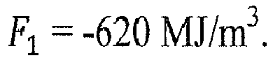
- Here, the physical parameters λ 0 and c P0 ρ 0 were expressed as dimensionless variables by dividing by the respective physical parameter of methane; therefore, all coefficients have the dimension of energy per unit volume.
- The coefficients A i , Bi, Ci, Di, Ei, Fi, i = 1,2,3, are stored in lookup table LUT2 (box 611).
- In
step 612, the resulting combustion parameters are outputted. -
Figure 7 illustrates the quality of a regression analysis for 650 natural gases, including both so-called L gases and H gases. On the horizontal axis, the "true" calorific value per unit volume at standard conditions,
values 
- In alternative embodiments, the thermal conductivity λ = λ(T) and the specific heat per unit volume, cPρ = cP (T) ρ(P,T), can be determined at the actual temperature T and pressure P, by using the above procedure, employing the actual volumetric flow rate dV/dt rather than the standardized volumetric flow rate Q and skipping temperature compensation of cP and A. Also in this case equations of the same form as equations (11)-(13) can be used; however, the coefficients A i , Bi, Ci, Di, Ei, Fi, i = 1,2,3, would have to be known for the actual pressure and temperature. If pressure and temperature are not constant, lookup table LUT2 would correspondingly contain the coefficients at more than one temperature and pressure and would thus be more complex.
- All or part of
control device 500 may be implemented as a dedicated digital signal processor (DSP) or as a general-purpose computer with a processor that executes software causing the processor to carry out the above-described steps. Consequently, the presently described method can be embodied in a computer program for execution on a general-purpose computer or on a dedicated DSP. - While there are shown and described presently preferred embodiments of the invention, it is to be understood that the invention is not limited thereto but may be otherwise variously embodied and practiced within the scope of the following claims.
Claims (15)
- A method for determining a combustion parameter of a gas in a gas flow (G), the method comprising:determining a flow velocity (ν) or a volumetric flow rate (dV/dt) of the gas in the gas flow (G);operating a thermal flow sensor (100) exposed to the gas flow (G);calculating a heat transfer parameter (λ 0) and a heat capacity parameter (c p0 ρ 0) of the gas from an output of the thermal flow sensor (100) and from the flow velocity (ν) or volumetric flow rate (dV/dt); andcalculating the combustion parameter (Hρ; IW; NM ) of the gas from the heat transfer parameter (λ 0) and the heat capacity parameter (c p0 ρ 0).
- The method of claim 1, wherein determining the heat transfer parameter (λ 0) and the heat capacity parameter (c p0 ρ 0) comprises:determining the heat transfer parameter (λ 0) and a mass flow parameter (φ) of the gas flow from the output of the thermal flow sensor;calculating the heat capacity parameter (c p0 ρ 0) from the mass flow parameter (φ), from the flow velocity (ν) or volumetric flow rate (dV/dt), and from the heat transfer parameter (λ 0).
- The method of claim 2, wherein the thermal flow sensor (100) comprises a heating element (101), a first temperature sensor (102) upstream of the heating element (101), and a second temperature sensor (103) downstream of the heating element (101), and wherein the method comprises:determining a first temperature value (T 1) at the first temperature sensor (102) and a second temperature value (T 2) at the second temperature sensor (103) under action of the heating element (101);calculating the heat transfer parameter (λ 0) and the mass flow parameter (φ) taking into account said first and second temperature values (T 1, T 2).
- The method of any one of the preceding claims,
wherein the heat transfer parameter (λ 0) is thermal conductivity, and
wherein the heat capacity parameter (c p0 ρ 0) is a volumetric heat capacity of the gas. - The method of any one of the preceding claims, wherein the heat transfer parameter (λ 0) and the heat capacity parameter (c p0 ρ 0) are calculated for predefined standard conditions, taking into account an actual gas temperature (T) and an actual gas pressure (P), and wherein the combustion parameter (Hρ; IW; NM ) of the gas is calculated from the heat transfer parameter (λ 0) and the heat capacity parameter (c p0 ρ 0) at said standard conditions.
- The method of claim 5, wherein calculating the heat capacity parameter (c p0 ρ 0) comprises:calculating, from the measured flow velocity (ν) or volumetric flow rate (dV/dt), a standardized flow velocity or standardized volumetric flow rate (Q) at standard conditions, taking into account the actual gas temperature (T) and the actual gas pressure (P); andemploying the standardized flow velocity or standardized volumetric flow rate (Q) to obtain a value indicative of the heat capacity parameter (c p0 ρ 0) at said standard conditions.
- The method of any one of the preceding claims, wherein the combustion parameter (Hρ; IW; NM ) is one of the following:a calorific value, in particular, heat of combustion per unit volume (Hρ);Wobbe index (IW ); andmethane number (NM ).
- The method of any one of the preceding claims, wherein the combustion parameter (Hρ; IW; NM ) is calculated as a polynomial of the heat transfer parameter (λ 0) and the heat capacity parameter (c p0 ρ 0), the polynomial having empirically determined coefficients.
- A method for measuring a volumetric flow rate (dV/dt) of a gas in a gas flow (G), in particular, the method of any one of the preceding claims, the method comprising:passing the gas flow (G) through at least one chamber (211, 212, 213, 214) that defines a variable volume, gas being alternatingly admitted into the chamber (211, 212, 213, 214) and being subsequently again expelled from the chamber (211, 212, 213, 214), the alternate admission and expulsion causing oscillations of the gas flow (G);detecting an oscillation signal by a thermal flow sensor (100), the oscillation signal being indicative of the oscillations of the gas flow (G); andcalculating the volumetric flow rate (dV/dt) based on the oscillation signal.
- A gas sensor for determining a combustion parameter (Hρ; IW; NM ) of a gas in a gas flow (G), the gas sensor comprising:a thermal flow sensor (100) configured to be exposed to the gas flow (G); anda control device (500) configured to carry out the following method:receiving an indication of a flow velocity (v) or a volumetric flow rate (dV/dt) of the gas in the gas flow (G);operating the thermal flow sensor (100);calculating a heat transfer parameter (λ 0) and a heat capacity parameter (c p0 ρ 0) of the gas from an output of the thermal flow sensor (100) and from the flow velocity (v) or volumetric flow rate (dV/dt); andcalculating the combustion parameter (Hρ; IW; NM ) of the gas from the heat transfer parameter (λ 0) and the heat capacity parameter (c p0 ρ 0).
- The gas sensor of claim 10, further comprising a volumetric flow sensor (200) for determining the flow velocity (ν) or the volumetric flow rate (dV/dt) of the gas in the gas flow (G).
- The gas sensor of claim 10 or 11,
wherein the thermal flow sensor (100) comprises a heating element (101), a first temperature sensor (102) upstream of the heating element (101), and a second temperature sensor (103) downstream of the heating element (101), and wherein the control device (500) is configured to carry out the following steps:operating the thermal flow sensor (100) to determine a first temperature value (T 1) at the first temperature sensor (102) and a second temperature value (T 2) at the second temperature sensor (103) under action of the heating element (101);calculating the heat transfer parameter (λ 0) and a mass flow parameter (φ) of the gas, taking into account said first and second temperature values (T 1 , T 2); andcalculating the heat capacity parameter (c p0 ρ 0) from the mass flow parameter (φ), from the flow velocity (v) or volumetric flow rate (dV/dt), and from the heat transfer parameter (λ 0). - The gas sensor of any one of claims 10-12,
wherein the volumetric flow sensor (200) is a bellows-type volumetric flow sensor comprising at least one chamber (211, 212, 213, 214) that defines a variable volume, the volumetric flow sensor (200) being configured to alternatingly admit gas to the chamber (211, 212, 213, 214) and to subsequently again expel the gas from the chamber (211, 212, 213, 214), the alternate admission and expulsion causing oscillations of the gas flow (G), and
wherein the control device (500) is configured to carry out the following method:detecting an oscillation signal based on signals from the thermal flow sensor (100), the oscillation signal being indicative of the oscillations of the gas flow (G); anddetermining the volumetric flow rate (dV/dt) based on the oscillation signal. - A gas sensor for determining a volumetric flow rate (dV/dt) of a gas in a gas flow (G), the gas sensor comprising:a volumetric flow sensor (200) of the bellows type comprising at least one chamber (211, 212, 213, 214) that defines a variable volume, the volumetric flow sensor (200) being configured to alternatingly admit gas to the chamber (211,212, 213, 214) and to subsequently again expel the gas from the chamber (211, 212, 213, 214), the alternate admission and expulsion causing oscillations of the gas flow (G);a thermal flow sensor (100) configured to be exposed to the gas flow (G); anda control device (500) configured to carry out the following method:detecting an oscillation signal based on signals from the thermal flow sensor (100), the oscillation signal being indicative of the oscillations of the gas flow (G); anddetermining the volumetric flow rate (dV/dt) based on the oscillation signal.
- A computer program comprising computer program code that, when carried out in a control device (500) of a gas sensor according to any one of claims 10-14, causes the control device (500) to carry out a method according to any one of claims 1-9.
Priority Applications (1)
| Application Number | Priority Date | Filing Date | Title |
|---|---|---|---|
| EP15188323.8A EP3153854B1 (en) | 2015-10-05 | 2015-10-05 | Determination of volumetric flow rate of a gas in a gas flow |
Applications Claiming Priority (1)
| Application Number | Priority Date | Filing Date | Title |
|---|---|---|---|
| EP15188323.8A EP3153854B1 (en) | 2015-10-05 | 2015-10-05 | Determination of volumetric flow rate of a gas in a gas flow |
Publications (2)
| Publication Number | Publication Date |
|---|---|
| EP3153854A1 true EP3153854A1 (en) | 2017-04-12 |
| EP3153854B1 EP3153854B1 (en) | 2021-03-31 |
Family
ID=54291077
Family Applications (1)
| Application Number | Title | Priority Date | Filing Date |
|---|---|---|---|
| EP15188323.8A Active EP3153854B1 (en) | 2015-10-05 | 2015-10-05 | Determination of volumetric flow rate of a gas in a gas flow |
Country Status (1)
| Country | Link |
|---|---|
| EP (1) | EP3153854B1 (en) |
Cited By (8)
| Publication number | Priority date | Publication date | Assignee | Title |
|---|---|---|---|---|
| EP3457093A1 (en) | 2018-05-28 | 2019-03-20 | Sensirion AG | Thermal gas measuring device |
| EP3502687A1 (en) | 2017-12-20 | 2019-06-26 | Sensirion AG | Determination of gas parameters |
| US10942139B2 (en) | 2017-06-30 | 2021-03-09 | Sensirion Ag | Operation method for flow sensor device |
| WO2021050033A1 (en) * | 2019-09-09 | 2021-03-18 | Micro Motion, Inc. | Systems and methods for live determination of fluid energy content |
| EP3812753A1 (en) | 2019-10-24 | 2021-04-28 | Sensirion AG | Determination of gas-specific parameters from heat transfer in the temperature jump regime |
| RU2792287C1 (en) * | 2019-09-09 | 2023-03-21 | Майкро Моушн, Инк. | System and method for operational determination of the calority of fluid media |
| US12228561B2 (en) | 2019-10-03 | 2025-02-18 | Micro Motion, Inc. | Systems and methods for inferring energy and burning properties of a fluid in a pipeline |
| CN121252997A (en) * | 2025-12-03 | 2026-01-02 | 康跃科技(山东)有限公司 | Method and system for measuring temperature of port of gas compressor |
Families Citing this family (1)
| Publication number | Priority date | Publication date | Assignee | Title |
|---|---|---|---|---|
| US12474285B2 (en) | 2023-03-17 | 2025-11-18 | Honeywell International, Inc. | Closed-meshed energy measurement in the gas network |
Citations (12)
| Publication number | Priority date | Publication date | Assignee | Title |
|---|---|---|---|---|
| DE4118781A1 (en) | 1991-06-07 | 1992-12-10 | Rmg Messtechnik Gmbh | METHOD AND DEVICE FOR THE COMBUSTION-FREE DETERMINATION OF THE WOB NUMBER AND / OR THE COMBUSTION VALUE OF A GAS |
| EP0554095A2 (en) * | 1992-01-30 | 1993-08-04 | Honeywell Inc. | Determination of fuel characteristics |
| WO2001018500A1 (en) * | 1999-09-09 | 2001-03-15 | Sensirion Ag | Method and device for precision mass flow measurement |
| WO2001098736A1 (en) | 2000-06-23 | 2001-12-27 | Sensirion Ag | Gas meter and method for detecting a consumed amount of gas |
| DE10122039A1 (en) | 2001-05-07 | 2002-11-14 | Ruhrgas Ag | Method and device for determining a characteristic value representative of the nature of a gas |
| US7188519B2 (en) | 2002-11-27 | 2007-03-13 | Sensirion Ag | Device and method for measuring the flow and at least one material parameter of a fluid |
| US7377152B2 (en) | 2002-10-18 | 2008-05-27 | Brooks Instrument, Llc | Method and device for determining a characteristic value that is representative of the condition of a gas |
| WO2012021999A1 (en) | 2010-08-17 | 2012-02-23 | Sensirion Ag | Flow sensor arrangement |
| EP2527779A2 (en) | 2011-05-25 | 2012-11-28 | Raytheon Company | Retractable rotary laser turret |
| EP2574918A1 (en) * | 2011-09-28 | 2013-04-03 | Mems Ag | Microthermal method and sensor for determining physical gas properties |
| EP2806271A1 (en) * | 2013-05-24 | 2014-11-26 | Mems Ag | Method and measuring device for determining physical gas properties |
| WO2015075278A1 (en) | 2015-03-05 | 2015-05-28 | Sensirion Ag | Determination of fluid parameters |
-
2015
- 2015-10-05 EP EP15188323.8A patent/EP3153854B1/en active Active
Patent Citations (12)
| Publication number | Priority date | Publication date | Assignee | Title |
|---|---|---|---|---|
| DE4118781A1 (en) | 1991-06-07 | 1992-12-10 | Rmg Messtechnik Gmbh | METHOD AND DEVICE FOR THE COMBUSTION-FREE DETERMINATION OF THE WOB NUMBER AND / OR THE COMBUSTION VALUE OF A GAS |
| EP0554095A2 (en) * | 1992-01-30 | 1993-08-04 | Honeywell Inc. | Determination of fuel characteristics |
| WO2001018500A1 (en) * | 1999-09-09 | 2001-03-15 | Sensirion Ag | Method and device for precision mass flow measurement |
| WO2001098736A1 (en) | 2000-06-23 | 2001-12-27 | Sensirion Ag | Gas meter and method for detecting a consumed amount of gas |
| DE10122039A1 (en) | 2001-05-07 | 2002-11-14 | Ruhrgas Ag | Method and device for determining a characteristic value representative of the nature of a gas |
| US7377152B2 (en) | 2002-10-18 | 2008-05-27 | Brooks Instrument, Llc | Method and device for determining a characteristic value that is representative of the condition of a gas |
| US7188519B2 (en) | 2002-11-27 | 2007-03-13 | Sensirion Ag | Device and method for measuring the flow and at least one material parameter of a fluid |
| WO2012021999A1 (en) | 2010-08-17 | 2012-02-23 | Sensirion Ag | Flow sensor arrangement |
| EP2527779A2 (en) | 2011-05-25 | 2012-11-28 | Raytheon Company | Retractable rotary laser turret |
| EP2574918A1 (en) * | 2011-09-28 | 2013-04-03 | Mems Ag | Microthermal method and sensor for determining physical gas properties |
| EP2806271A1 (en) * | 2013-05-24 | 2014-11-26 | Mems Ag | Method and measuring device for determining physical gas properties |
| WO2015075278A1 (en) | 2015-03-05 | 2015-05-28 | Sensirion Ag | Determination of fluid parameters |
Non-Patent Citations (3)
| Title |
|---|
| PPDS, 1 October 2015 (2015-10-01), Retrieved from the Internet <URL:http://www.tuv-sud.co.uk/uk-en/about-tuev-sued/tuev-sued-in-the-uk/nel/ppds-thermodynamic-properties-suite> |
| REFPROP NIST, 1 October 2015 (2015-10-01), Retrieved from the Internet <URL:http://www.nist.gov/srd/nist23.cfin> |
| REPORT ON GAS COMPOSITION RANGE IN EUROPE, 1 October 2015 (2015-10-01), Retrieved from the Internet <URL:http://www.ingas-eu.org/docs/DB0.1.pdf> |
Cited By (14)
| Publication number | Priority date | Publication date | Assignee | Title |
|---|---|---|---|---|
| US10942139B2 (en) | 2017-06-30 | 2021-03-09 | Sensirion Ag | Operation method for flow sensor device |
| EP3502687A1 (en) | 2017-12-20 | 2019-06-26 | Sensirion AG | Determination of gas parameters |
| CN110031503A (en) * | 2017-12-20 | 2019-07-19 | 盛思锐股份公司 | The determination of gas parameter |
| EP3457093A1 (en) | 2018-05-28 | 2019-03-20 | Sensirion AG | Thermal gas measuring device |
| CN114424062A (en) * | 2019-09-09 | 2022-04-29 | 高准有限公司 | System and method for real-time determination of fluid energy content |
| WO2021050033A1 (en) * | 2019-09-09 | 2021-03-18 | Micro Motion, Inc. | Systems and methods for live determination of fluid energy content |
| KR20220054682A (en) * | 2019-09-09 | 2022-05-03 | 마이크로 모우션, 인코포레이티드 | Systems and Methods for Live Determination of Fluid Energy Content |
| RU2792287C1 (en) * | 2019-09-09 | 2023-03-21 | Майкро Моушн, Инк. | System and method for operational determination of the calority of fluid media |
| AU2019465533B2 (en) * | 2019-09-09 | 2023-04-20 | Micro Motion, Inc. | Systems and methods for live determination of fluid energy content |
| KR102704784B1 (en) | 2019-09-09 | 2024-09-09 | 마이크로 모우션, 인코포레이티드 | Systems and methods for live determination of fluid energy content |
| RU2793606C1 (en) * | 2019-10-03 | 2023-04-04 | Майкро Моушн, Инк. | System and method for determining energy content of flowing fluid medium in gaseous state |
| US12228561B2 (en) | 2019-10-03 | 2025-02-18 | Micro Motion, Inc. | Systems and methods for inferring energy and burning properties of a fluid in a pipeline |
| EP3812753A1 (en) | 2019-10-24 | 2021-04-28 | Sensirion AG | Determination of gas-specific parameters from heat transfer in the temperature jump regime |
| CN121252997A (en) * | 2025-12-03 | 2026-01-02 | 康跃科技(山东)有限公司 | Method and system for measuring temperature of port of gas compressor |
Also Published As
| Publication number | Publication date |
|---|---|
| EP3153854B1 (en) | 2021-03-31 |
Similar Documents
| Publication | Publication Date | Title |
|---|---|---|
| EP3153854B1 (en) | Determination of volumetric flow rate of a gas in a gas flow | |
| JP6731936B2 (en) | MEMS thermal type flow sensor and method for measuring fluid flow rate | |
| TWI476377B (en) | Mass-flow meter and mass-flow controller | |
| EP3502687B1 (en) | Determination of gas parameters | |
| US11226300B2 (en) | Determination of fluid parameters | |
| US20150316401A1 (en) | Thermal, flow measuring apparatus and method for determining and/or monitoring flow of a medium | |
| US20160138951A1 (en) | Method and measuring apparatus for determining specific quantities for gas quality | |
| RU2283479C2 (en) | Method for determining flow of gas mixture and a gas counter | |
| JP5961962B2 (en) | Boiler steam amount measuring method, boiler load analyzing method, boiler steam amount measuring device, and boiler load analyzing device | |
| US9964423B2 (en) | Device and method for determining the mass-flow of a fluid | |
| Cascetta et al. | Calibration procedures and uncertainty analysis for a thermal mass gas flowmeter of a new generation | |
| JP2019035640A (en) | Thermal flow meter | |
| JP2019052950A (en) | Thermal flow meter | |
| CN118235028A (en) | Method and system for determining the temperature of a fluid flowing through a pipe | |
| JP7037883B2 (en) | Exhaust flow rate measuring device, fuel consumption measuring device, program for exhaust gas flow rate measuring device, and exhaust gas flow rate measuring method | |
| CN115165961A (en) | Gas constant-pressure specific heat capacity measuring device and measuring method thereof | |
| WO2013175664A1 (en) | Steam pressure measurement device for boiler and steam amount measurement device for boiler | |
| WO2002090920A3 (en) | Method and device for determining a characteristic value that is representative of the condition of a gas | |
| JP5690003B2 (en) | Specific heat capacity measurement system and flow rate measurement system | |
| WO2019064819A1 (en) | Flow rate measurement device | |
| TW201116960A (en) | Mass flow controller | |
| EP3683555A1 (en) | Flow rate measurement device, gas meter provided with flow rate measurement device, and flow rate measurement device unit for gas meter | |
| KR20110006869U (en) | Non-balanced length sensor element of thermal mass flow meter | |
| CN110291372B (en) | Calorimetric probe and method for calorimetric measurement | |
| Zajc et al. | Rapid determination of the calorific value by means of a novel gas quality sensor |
Legal Events
| Date | Code | Title | Description |
|---|---|---|---|
| PUAI | Public reference made under article 153(3) epc to a published international application that has entered the european phase |
Free format text: ORIGINAL CODE: 0009012 |
|
| STAA | Information on the status of an ep patent application or granted ep patent |
Free format text: STATUS: THE APPLICATION HAS BEEN PUBLISHED |
|
| AK | Designated contracting states |
Kind code of ref document: A1 Designated state(s): AL AT BE BG CH CY CZ DE DK EE ES FI FR GB GR HR HU IE IS IT LI LT LU LV MC MK MT NL NO PL PT RO RS SE SI SK SM TR |
|
| AX | Request for extension of the european patent |
Extension state: BA ME |
|
| STAA | Information on the status of an ep patent application or granted ep patent |
Free format text: STATUS: REQUEST FOR EXAMINATION WAS MADE |
|
| 17P | Request for examination filed |
Effective date: 20170814 |
|
| RBV | Designated contracting states (corrected) |
Designated state(s): AL AT BE BG CH CY CZ DE DK EE ES FI FR GB GR HR HU IE IS IT LI LT LU LV MC MK MT NL NO PL PT RO RS SE SI SK SM TR |
|
| RIC1 | Information provided on ipc code assigned before grant |
Ipc: G01N 33/22 20060101AFI20200513BHEP Ipc: G01N 25/18 20060101ALI20200513BHEP Ipc: G01F 1/68 20060101ALI20200513BHEP |
|
| GRAJ | Information related to disapproval of communication of intention to grant by the applicant or resumption of examination proceedings by the epo deleted |
Free format text: ORIGINAL CODE: EPIDOSDIGR1 |
|
| GRAP | Despatch of communication of intention to grant a patent |
Free format text: ORIGINAL CODE: EPIDOSNIGR1 |
|
| RIN1 | Information on inventor provided before grant (corrected) |
Inventor name: HORNUNG, MARK Inventor name: RUEEGG, ANDREAS |
|
| GRAP | Despatch of communication of intention to grant a patent |
Free format text: ORIGINAL CODE: EPIDOSNIGR1 |
|
| STAA | Information on the status of an ep patent application or granted ep patent |
Free format text: STATUS: GRANT OF PATENT IS INTENDED |
|
| INTG | Intention to grant announced |
Effective date: 20201020 |
|
| GRAS | Grant fee paid |
Free format text: ORIGINAL CODE: EPIDOSNIGR3 |
|
| GRAA | (expected) grant |
Free format text: ORIGINAL CODE: 0009210 |
|
| STAA | Information on the status of an ep patent application or granted ep patent |
Free format text: STATUS: THE PATENT HAS BEEN GRANTED |
|
| AK | Designated contracting states |
Kind code of ref document: B1 Designated state(s): AL AT BE BG CH CY CZ DE DK EE ES FI FR GB GR HR HU IE IS IT LI LT LU LV MC MK MT NL NO PL PT RO RS SE SI SK SM TR |
|
| REG | Reference to a national code |
Ref country code: GB Ref legal event code: FG4D Ref country code: CH Ref legal event code: EP |
|
| REG | Reference to a national code |
Ref country code: AT Ref legal event code: REF Ref document number: 1377520 Country of ref document: AT Kind code of ref document: T Effective date: 20210415 |
|
| REG | Reference to a national code |
Ref country code: DE Ref legal event code: R096 Ref document number: 602015067402 Country of ref document: DE |
|
| REG | Reference to a national code |
Ref country code: IE Ref legal event code: FG4D |
|
| REG | Reference to a national code |
Ref country code: LT Ref legal event code: MG9D |
|
| PG25 | Lapsed in a contracting state [announced via postgrant information from national office to epo] |
Ref country code: BG Free format text: LAPSE BECAUSE OF FAILURE TO SUBMIT A TRANSLATION OF THE DESCRIPTION OR TO PAY THE FEE WITHIN THE PRESCRIBED TIME-LIMIT Effective date: 20210630 Ref country code: NO Free format text: LAPSE BECAUSE OF FAILURE TO SUBMIT A TRANSLATION OF THE DESCRIPTION OR TO PAY THE FEE WITHIN THE PRESCRIBED TIME-LIMIT Effective date: 20210630 Ref country code: FI Free format text: LAPSE BECAUSE OF FAILURE TO SUBMIT A TRANSLATION OF THE DESCRIPTION OR TO PAY THE FEE WITHIN THE PRESCRIBED TIME-LIMIT Effective date: 20210331 Ref country code: HR Free format text: LAPSE BECAUSE OF FAILURE TO SUBMIT A TRANSLATION OF THE DESCRIPTION OR TO PAY THE FEE WITHIN THE PRESCRIBED TIME-LIMIT Effective date: 20210331 |
|
| PG25 | Lapsed in a contracting state [announced via postgrant information from national office to epo] |
Ref country code: LV Free format text: LAPSE BECAUSE OF FAILURE TO SUBMIT A TRANSLATION OF THE DESCRIPTION OR TO PAY THE FEE WITHIN THE PRESCRIBED TIME-LIMIT Effective date: 20210331 Ref country code: RS Free format text: LAPSE BECAUSE OF FAILURE TO SUBMIT A TRANSLATION OF THE DESCRIPTION OR TO PAY THE FEE WITHIN THE PRESCRIBED TIME-LIMIT Effective date: 20210331 Ref country code: SE Free format text: LAPSE BECAUSE OF FAILURE TO SUBMIT A TRANSLATION OF THE DESCRIPTION OR TO PAY THE FEE WITHIN THE PRESCRIBED TIME-LIMIT Effective date: 20210331 |
|
| REG | Reference to a national code |
Ref country code: NL Ref legal event code: MP Effective date: 20210331 |
|
| REG | Reference to a national code |
Ref country code: AT Ref legal event code: MK05 Ref document number: 1377520 Country of ref document: AT Kind code of ref document: T Effective date: 20210331 |
|
| PG25 | Lapsed in a contracting state [announced via postgrant information from national office to epo] |
Ref country code: NL Free format text: LAPSE BECAUSE OF FAILURE TO SUBMIT A TRANSLATION OF THE DESCRIPTION OR TO PAY THE FEE WITHIN THE PRESCRIBED TIME-LIMIT Effective date: 20210331 Ref country code: LT Free format text: LAPSE BECAUSE OF FAILURE TO SUBMIT A TRANSLATION OF THE DESCRIPTION OR TO PAY THE FEE WITHIN THE PRESCRIBED TIME-LIMIT Effective date: 20210331 Ref country code: CZ Free format text: LAPSE BECAUSE OF FAILURE TO SUBMIT A TRANSLATION OF THE DESCRIPTION OR TO PAY THE FEE WITHIN THE PRESCRIBED TIME-LIMIT Effective date: 20210331 Ref country code: EE Free format text: LAPSE BECAUSE OF FAILURE TO SUBMIT A TRANSLATION OF THE DESCRIPTION OR TO PAY THE FEE WITHIN THE PRESCRIBED TIME-LIMIT Effective date: 20210331 Ref country code: AT Free format text: LAPSE BECAUSE OF FAILURE TO SUBMIT A TRANSLATION OF THE DESCRIPTION OR TO PAY THE FEE WITHIN THE PRESCRIBED TIME-LIMIT Effective date: 20210331 Ref country code: SM Free format text: LAPSE BECAUSE OF FAILURE TO SUBMIT A TRANSLATION OF THE DESCRIPTION OR TO PAY THE FEE WITHIN THE PRESCRIBED TIME-LIMIT Effective date: 20210331 |
|
| PG25 | Lapsed in a contracting state [announced via postgrant information from national office to epo] |
Ref country code: IS Free format text: LAPSE BECAUSE OF FAILURE TO SUBMIT A TRANSLATION OF THE DESCRIPTION OR TO PAY THE FEE WITHIN THE PRESCRIBED TIME-LIMIT Effective date: 20210731 Ref country code: PL Free format text: LAPSE BECAUSE OF FAILURE TO SUBMIT A TRANSLATION OF THE DESCRIPTION OR TO PAY THE FEE WITHIN THE PRESCRIBED TIME-LIMIT Effective date: 20210331 Ref country code: PT Free format text: LAPSE BECAUSE OF FAILURE TO SUBMIT A TRANSLATION OF THE DESCRIPTION OR TO PAY THE FEE WITHIN THE PRESCRIBED TIME-LIMIT Effective date: 20210802 Ref country code: ES Free format text: LAPSE BECAUSE OF FAILURE TO SUBMIT A TRANSLATION OF THE DESCRIPTION OR TO PAY THE FEE WITHIN THE PRESCRIBED TIME-LIMIT Effective date: 20210331 Ref country code: SK Free format text: LAPSE BECAUSE OF FAILURE TO SUBMIT A TRANSLATION OF THE DESCRIPTION OR TO PAY THE FEE WITHIN THE PRESCRIBED TIME-LIMIT Effective date: 20210331 Ref country code: RO Free format text: LAPSE BECAUSE OF FAILURE TO SUBMIT A TRANSLATION OF THE DESCRIPTION OR TO PAY THE FEE WITHIN THE PRESCRIBED TIME-LIMIT Effective date: 20210331 |
|
| REG | Reference to a national code |
Ref country code: DE Ref legal event code: R097 Ref document number: 602015067402 Country of ref document: DE |
|
| PG25 | Lapsed in a contracting state [announced via postgrant information from national office to epo] |
Ref country code: DK Free format text: LAPSE BECAUSE OF FAILURE TO SUBMIT A TRANSLATION OF THE DESCRIPTION OR TO PAY THE FEE WITHIN THE PRESCRIBED TIME-LIMIT Effective date: 20210331 Ref country code: AL Free format text: LAPSE BECAUSE OF FAILURE TO SUBMIT A TRANSLATION OF THE DESCRIPTION OR TO PAY THE FEE WITHIN THE PRESCRIBED TIME-LIMIT Effective date: 20210331 |
|
| PLBE | No opposition filed within time limit |
Free format text: ORIGINAL CODE: 0009261 |
|
| STAA | Information on the status of an ep patent application or granted ep patent |
Free format text: STATUS: NO OPPOSITION FILED WITHIN TIME LIMIT |
|
| 26N | No opposition filed |
Effective date: 20220104 |
|
| PG25 | Lapsed in a contracting state [announced via postgrant information from national office to epo] |
Ref country code: IS Free format text: LAPSE BECAUSE OF FAILURE TO SUBMIT A TRANSLATION OF THE DESCRIPTION OR TO PAY THE FEE WITHIN THE PRESCRIBED TIME-LIMIT Effective date: 20210731 |
|
| REG | Reference to a national code |
Ref country code: BE Ref legal event code: MM Effective date: 20211031 |
|
| GBPC | Gb: european patent ceased through non-payment of renewal fee |
Effective date: 20211005 |
|
| PG25 | Lapsed in a contracting state [announced via postgrant information from national office to epo] |
Ref country code: MC Free format text: LAPSE BECAUSE OF FAILURE TO SUBMIT A TRANSLATION OF THE DESCRIPTION OR TO PAY THE FEE WITHIN THE PRESCRIBED TIME-LIMIT Effective date: 20210331 |
|
| PG25 | Lapsed in a contracting state [announced via postgrant information from national office to epo] |
Ref country code: LU Free format text: LAPSE BECAUSE OF NON-PAYMENT OF DUE FEES Effective date: 20211005 Ref country code: IT Free format text: LAPSE BECAUSE OF FAILURE TO SUBMIT A TRANSLATION OF THE DESCRIPTION OR TO PAY THE FEE WITHIN THE PRESCRIBED TIME-LIMIT Effective date: 20210331 Ref country code: GB Free format text: LAPSE BECAUSE OF NON-PAYMENT OF DUE FEES Effective date: 20211005 Ref country code: BE Free format text: LAPSE BECAUSE OF NON-PAYMENT OF DUE FEES Effective date: 20211031 |
|
| PG25 | Lapsed in a contracting state [announced via postgrant information from national office to epo] |
Ref country code: FR Free format text: LAPSE BECAUSE OF NON-PAYMENT OF DUE FEES Effective date: 20211031 |
|
| PG25 | Lapsed in a contracting state [announced via postgrant information from national office to epo] |
Ref country code: IE Free format text: LAPSE BECAUSE OF NON-PAYMENT OF DUE FEES Effective date: 20211005 |
|
| PG25 | Lapsed in a contracting state [announced via postgrant information from national office to epo] |
Ref country code: HU Free format text: LAPSE BECAUSE OF FAILURE TO SUBMIT A TRANSLATION OF THE DESCRIPTION OR TO PAY THE FEE WITHIN THE PRESCRIBED TIME-LIMIT; INVALID AB INITIO Effective date: 20151005 |
|
| PG25 | Lapsed in a contracting state [announced via postgrant information from national office to epo] |
Ref country code: CY Free format text: LAPSE BECAUSE OF FAILURE TO SUBMIT A TRANSLATION OF THE DESCRIPTION OR TO PAY THE FEE WITHIN THE PRESCRIBED TIME-LIMIT Effective date: 20210331 |
|
| P01 | Opt-out of the competence of the unified patent court (upc) registered |
Effective date: 20230602 |
|
| PG25 | Lapsed in a contracting state [announced via postgrant information from national office to epo] |
Ref country code: GR Free format text: LAPSE BECAUSE OF FAILURE TO SUBMIT A TRANSLATION OF THE DESCRIPTION OR TO PAY THE FEE WITHIN THE PRESCRIBED TIME-LIMIT Effective date: 20210331 |
|
| PG25 | Lapsed in a contracting state [announced via postgrant information from national office to epo] |
Ref country code: MK Free format text: LAPSE BECAUSE OF FAILURE TO SUBMIT A TRANSLATION OF THE DESCRIPTION OR TO PAY THE FEE WITHIN THE PRESCRIBED TIME-LIMIT Effective date: 20210331 |
|
| PG25 | Lapsed in a contracting state [announced via postgrant information from national office to epo] |
Ref country code: MT Free format text: LAPSE BECAUSE OF FAILURE TO SUBMIT A TRANSLATION OF THE DESCRIPTION OR TO PAY THE FEE WITHIN THE PRESCRIBED TIME-LIMIT Effective date: 20210331 |
|
| REG | Reference to a national code |
Ref country code: CH Ref legal event code: U11 Free format text: ST27 STATUS EVENT CODE: U-0-0-U10-U11 (AS PROVIDED BY THE NATIONAL OFFICE) Effective date: 20251101 |
|
| PG25 | Lapsed in a contracting state [announced via postgrant information from national office to epo] |
Ref country code: TR Free format text: LAPSE BECAUSE OF FAILURE TO SUBMIT A TRANSLATION OF THE DESCRIPTION OR TO PAY THE FEE WITHIN THE PRESCRIBED TIME-LIMIT Effective date: 20210331 |
|
| PGFP | Annual fee paid to national office [announced via postgrant information from national office to epo] |
Ref country code: DE Payment date: 20251020 Year of fee payment: 11 |
|
| PGFP | Annual fee paid to national office [announced via postgrant information from national office to epo] |
Ref country code: CH Payment date: 20251101 Year of fee payment: 11 |