EP3153304B1 - Tête de soudage - Google Patents
Tête de soudage Download PDFInfo
- Publication number
- EP3153304B1 EP3153304B1 EP15188370.9A EP15188370A EP3153304B1 EP 3153304 B1 EP3153304 B1 EP 3153304B1 EP 15188370 A EP15188370 A EP 15188370A EP 3153304 B1 EP3153304 B1 EP 3153304B1
- Authority
- EP
- European Patent Office
- Prior art keywords
- lid
- welding
- welding head
- component
- head according
- Prior art date
- Legal status (The legal status is an assumption and is not a legal conclusion. Google has not performed a legal analysis and makes no representation as to the accuracy of the status listed.)
- Active
Links
- 238000003466 welding Methods 0.000 title claims description 131
- 230000006698 induction Effects 0.000 claims description 36
- 238000006073 displacement reaction Methods 0.000 claims description 9
- 238000007789 sealing Methods 0.000 claims description 9
- 210000003739 neck Anatomy 0.000 description 94
- 239000005022 packaging material Substances 0.000 description 23
- 230000001737 promoting effect Effects 0.000 description 21
- 230000008093 supporting effect Effects 0.000 description 21
- 230000033001 locomotion Effects 0.000 description 17
- 238000009826 distribution Methods 0.000 description 14
- 239000000463 material Substances 0.000 description 13
- 235000013305 food Nutrition 0.000 description 9
- 239000004033 plastic Substances 0.000 description 8
- 229920003023 plastic Polymers 0.000 description 8
- 230000009471 action Effects 0.000 description 6
- 238000004806 packaging method and process Methods 0.000 description 6
- 239000012530 fluid Substances 0.000 description 5
- 239000004020 conductor Substances 0.000 description 4
- 238000005304 joining Methods 0.000 description 4
- 230000008859 change Effects 0.000 description 3
- 230000001939 inductive effect Effects 0.000 description 3
- 230000003993 interaction Effects 0.000 description 3
- 238000003475 lamination Methods 0.000 description 3
- 238000004519 manufacturing process Methods 0.000 description 3
- 238000000034 method Methods 0.000 description 3
- -1 polypropylene Polymers 0.000 description 3
- 239000004698 Polyethylene Substances 0.000 description 2
- 239000005030 aluminium foil Substances 0.000 description 2
- IKZZIQXKLWDPCD-UHFFFAOYSA-N but-1-en-2-ol Chemical compound CCC(O)=C IKZZIQXKLWDPCD-UHFFFAOYSA-N 0.000 description 2
- 238000010438 heat treatment Methods 0.000 description 2
- 230000007246 mechanism Effects 0.000 description 2
- 239000000155 melt Substances 0.000 description 2
- 238000000465 moulding Methods 0.000 description 2
- 229920000573 polyethylene Polymers 0.000 description 2
- 238000012163 sequencing technique Methods 0.000 description 2
- 239000000243 solution Substances 0.000 description 2
- 238000011144 upstream manufacturing Methods 0.000 description 2
- MHAJPDPJQMAIIY-UHFFFAOYSA-N Hydrogen peroxide Chemical compound OO MHAJPDPJQMAIIY-UHFFFAOYSA-N 0.000 description 1
- 235000007688 Lycopersicon esculentum Nutrition 0.000 description 1
- 239000004743 Polypropylene Substances 0.000 description 1
- 240000003768 Solanum lycopersicum Species 0.000 description 1
- 230000003213 activating effect Effects 0.000 description 1
- 230000005540 biological transmission Effects 0.000 description 1
- 238000004891 communication Methods 0.000 description 1
- 230000006835 compression Effects 0.000 description 1
- 238000007906 compression Methods 0.000 description 1
- 230000008878 coupling Effects 0.000 description 1
- 238000010168 coupling process Methods 0.000 description 1
- 238000005859 coupling reaction Methods 0.000 description 1
- 230000007423 decrease Effects 0.000 description 1
- 239000002657 fibrous material Substances 0.000 description 1
- 238000009459 flexible packaging Methods 0.000 description 1
- 239000011888 foil Substances 0.000 description 1
- 235000015203 fruit juice Nutrition 0.000 description 1
- 239000011521 glass Substances 0.000 description 1
- 238000001746 injection moulding Methods 0.000 description 1
- 229910052500 inorganic mineral Inorganic materials 0.000 description 1
- 239000007788 liquid Substances 0.000 description 1
- 235000020191 long-life milk Nutrition 0.000 description 1
- 239000002184 metal Substances 0.000 description 1
- 229910052751 metal Inorganic materials 0.000 description 1
- 235000013336 milk Nutrition 0.000 description 1
- 239000008267 milk Substances 0.000 description 1
- 210000004080 milk Anatomy 0.000 description 1
- 239000011707 mineral Substances 0.000 description 1
- 229920001155 polypropylene Polymers 0.000 description 1
- 230000008569 process Effects 0.000 description 1
- 230000000717 retained effect Effects 0.000 description 1
- 235000015067 sauces Nutrition 0.000 description 1
- 230000001954 sterilising effect Effects 0.000 description 1
- 238000004659 sterilization and disinfection Methods 0.000 description 1
- 239000003206 sterilizing agent Substances 0.000 description 1
- 238000003860 storage Methods 0.000 description 1
- 239000000126 substance Substances 0.000 description 1
- 239000012815 thermoplastic material Substances 0.000 description 1
- 230000001131 transforming effect Effects 0.000 description 1
- 235000014101 wine Nutrition 0.000 description 1
Images


Classifications
-
- B—PERFORMING OPERATIONS; TRANSPORTING
- B29—WORKING OF PLASTICS; WORKING OF SUBSTANCES IN A PLASTIC STATE IN GENERAL
- B29C—SHAPING OR JOINING OF PLASTICS; SHAPING OF MATERIAL IN A PLASTIC STATE, NOT OTHERWISE PROVIDED FOR; AFTER-TREATMENT OF THE SHAPED PRODUCTS, e.g. REPAIRING
- B29C65/00—Joining or sealing of preformed parts, e.g. welding of plastics materials; Apparatus therefor
- B29C65/02—Joining or sealing of preformed parts, e.g. welding of plastics materials; Apparatus therefor by heating, with or without pressure
- B29C65/34—Joining or sealing of preformed parts, e.g. welding of plastics materials; Apparatus therefor by heating, with or without pressure using heated elements which remain in the joint, e.g. "verlorenes Schweisselement"
- B29C65/36—Joining or sealing of preformed parts, e.g. welding of plastics materials; Apparatus therefor by heating, with or without pressure using heated elements which remain in the joint, e.g. "verlorenes Schweisselement" heated by induction
- B29C65/3604—Joining or sealing of preformed parts, e.g. welding of plastics materials; Apparatus therefor by heating, with or without pressure using heated elements which remain in the joint, e.g. "verlorenes Schweisselement" heated by induction characterised by the type of elements heated by induction which remain in the joint
- B29C65/3644—Joining or sealing of preformed parts, e.g. welding of plastics materials; Apparatus therefor by heating, with or without pressure using heated elements which remain in the joint, e.g. "verlorenes Schweisselement" heated by induction characterised by the type of elements heated by induction which remain in the joint being a ribbon, band or strip
-
- B—PERFORMING OPERATIONS; TRANSPORTING
- B29—WORKING OF PLASTICS; WORKING OF SUBSTANCES IN A PLASTIC STATE IN GENERAL
- B29C—SHAPING OR JOINING OF PLASTICS; SHAPING OF MATERIAL IN A PLASTIC STATE, NOT OTHERWISE PROVIDED FOR; AFTER-TREATMENT OF THE SHAPED PRODUCTS, e.g. REPAIRING
- B29C65/00—Joining or sealing of preformed parts, e.g. welding of plastics materials; Apparatus therefor
- B29C65/78—Means for handling the parts to be joined, e.g. for making containers or hollow articles, e.g. means for handling sheets, plates, web-like materials, tubular articles, hollow articles or elements to be joined therewith; Means for discharging the joined articles from the joining apparatus
- B29C65/7802—Positioning the parts to be joined, e.g. aligning, indexing or centring
- B29C65/7805—Positioning the parts to be joined, e.g. aligning, indexing or centring the parts to be joined comprising positioning features
- B29C65/7814—Positioning the parts to be joined, e.g. aligning, indexing or centring the parts to be joined comprising positioning features in the form of inter-cooperating positioning features, e.g. tenons and mortises
-
- B—PERFORMING OPERATIONS; TRANSPORTING
- B29—WORKING OF PLASTICS; WORKING OF SUBSTANCES IN A PLASTIC STATE IN GENERAL
- B29C—SHAPING OR JOINING OF PLASTICS; SHAPING OF MATERIAL IN A PLASTIC STATE, NOT OTHERWISE PROVIDED FOR; AFTER-TREATMENT OF THE SHAPED PRODUCTS, e.g. REPAIRING
- B29C65/00—Joining or sealing of preformed parts, e.g. welding of plastics materials; Apparatus therefor
- B29C65/02—Joining or sealing of preformed parts, e.g. welding of plastics materials; Apparatus therefor by heating, with or without pressure
- B29C65/34—Joining or sealing of preformed parts, e.g. welding of plastics materials; Apparatus therefor by heating, with or without pressure using heated elements which remain in the joint, e.g. "verlorenes Schweisselement"
- B29C65/36—Joining or sealing of preformed parts, e.g. welding of plastics materials; Apparatus therefor by heating, with or without pressure using heated elements which remain in the joint, e.g. "verlorenes Schweisselement" heated by induction
- B29C65/3604—Joining or sealing of preformed parts, e.g. welding of plastics materials; Apparatus therefor by heating, with or without pressure using heated elements which remain in the joint, e.g. "verlorenes Schweisselement" heated by induction characterised by the type of elements heated by induction which remain in the joint
- B29C65/3656—Joining or sealing of preformed parts, e.g. welding of plastics materials; Apparatus therefor by heating, with or without pressure using heated elements which remain in the joint, e.g. "verlorenes Schweisselement" heated by induction characterised by the type of elements heated by induction which remain in the joint being a layer of a multilayer part to be joined, e.g. for joining plastic-metal laminates
-
- B—PERFORMING OPERATIONS; TRANSPORTING
- B29—WORKING OF PLASTICS; WORKING OF SUBSTANCES IN A PLASTIC STATE IN GENERAL
- B29C—SHAPING OR JOINING OF PLASTICS; SHAPING OF MATERIAL IN A PLASTIC STATE, NOT OTHERWISE PROVIDED FOR; AFTER-TREATMENT OF THE SHAPED PRODUCTS, e.g. REPAIRING
- B29C65/00—Joining or sealing of preformed parts, e.g. welding of plastics materials; Apparatus therefor
- B29C65/02—Joining or sealing of preformed parts, e.g. welding of plastics materials; Apparatus therefor by heating, with or without pressure
- B29C65/34—Joining or sealing of preformed parts, e.g. welding of plastics materials; Apparatus therefor by heating, with or without pressure using heated elements which remain in the joint, e.g. "verlorenes Schweisselement"
- B29C65/36—Joining or sealing of preformed parts, e.g. welding of plastics materials; Apparatus therefor by heating, with or without pressure using heated elements which remain in the joint, e.g. "verlorenes Schweisselement" heated by induction
- B29C65/3672—Joining or sealing of preformed parts, e.g. welding of plastics materials; Apparatus therefor by heating, with or without pressure using heated elements which remain in the joint, e.g. "verlorenes Schweisselement" heated by induction characterised by the composition of the elements heated by induction which remain in the joint
- B29C65/3676—Joining or sealing of preformed parts, e.g. welding of plastics materials; Apparatus therefor by heating, with or without pressure using heated elements which remain in the joint, e.g. "verlorenes Schweisselement" heated by induction characterised by the composition of the elements heated by induction which remain in the joint being metallic
- B29C65/368—Joining or sealing of preformed parts, e.g. welding of plastics materials; Apparatus therefor by heating, with or without pressure using heated elements which remain in the joint, e.g. "verlorenes Schweisselement" heated by induction characterised by the composition of the elements heated by induction which remain in the joint being metallic with a polymer coating
-
- B—PERFORMING OPERATIONS; TRANSPORTING
- B29—WORKING OF PLASTICS; WORKING OF SUBSTANCES IN A PLASTIC STATE IN GENERAL
- B29C—SHAPING OR JOINING OF PLASTICS; SHAPING OF MATERIAL IN A PLASTIC STATE, NOT OTHERWISE PROVIDED FOR; AFTER-TREATMENT OF THE SHAPED PRODUCTS, e.g. REPAIRING
- B29C65/00—Joining or sealing of preformed parts, e.g. welding of plastics materials; Apparatus therefor
- B29C65/48—Joining or sealing of preformed parts, e.g. welding of plastics materials; Apparatus therefor using adhesives, i.e. using supplementary joining material; solvent bonding
- B29C65/4805—Joining or sealing of preformed parts, e.g. welding of plastics materials; Apparatus therefor using adhesives, i.e. using supplementary joining material; solvent bonding characterised by the type of adhesives
- B29C65/481—Non-reactive adhesives, e.g. physically hardening adhesives
- B29C65/4815—Hot melt adhesives, e.g. thermoplastic adhesives
-
- B—PERFORMING OPERATIONS; TRANSPORTING
- B29—WORKING OF PLASTICS; WORKING OF SUBSTANCES IN A PLASTIC STATE IN GENERAL
- B29C—SHAPING OR JOINING OF PLASTICS; SHAPING OF MATERIAL IN A PLASTIC STATE, NOT OTHERWISE PROVIDED FOR; AFTER-TREATMENT OF THE SHAPED PRODUCTS, e.g. REPAIRING
- B29C65/00—Joining or sealing of preformed parts, e.g. welding of plastics materials; Apparatus therefor
- B29C65/48—Joining or sealing of preformed parts, e.g. welding of plastics materials; Apparatus therefor using adhesives, i.e. using supplementary joining material; solvent bonding
- B29C65/50—Joining or sealing of preformed parts, e.g. welding of plastics materials; Apparatus therefor using adhesives, i.e. using supplementary joining material; solvent bonding using adhesive tape, e.g. thermoplastic tape; using threads or the like
- B29C65/5007—Joining or sealing of preformed parts, e.g. welding of plastics materials; Apparatus therefor using adhesives, i.e. using supplementary joining material; solvent bonding using adhesive tape, e.g. thermoplastic tape; using threads or the like characterised by the structure of said adhesive tape, threads or the like
- B29C65/5021—Joining or sealing of preformed parts, e.g. welding of plastics materials; Apparatus therefor using adhesives, i.e. using supplementary joining material; solvent bonding using adhesive tape, e.g. thermoplastic tape; using threads or the like characterised by the structure of said adhesive tape, threads or the like being multi-layered
-
- B—PERFORMING OPERATIONS; TRANSPORTING
- B29—WORKING OF PLASTICS; WORKING OF SUBSTANCES IN A PLASTIC STATE IN GENERAL
- B29C—SHAPING OR JOINING OF PLASTICS; SHAPING OF MATERIAL IN A PLASTIC STATE, NOT OTHERWISE PROVIDED FOR; AFTER-TREATMENT OF THE SHAPED PRODUCTS, e.g. REPAIRING
- B29C65/00—Joining or sealing of preformed parts, e.g. welding of plastics materials; Apparatus therefor
- B29C65/48—Joining or sealing of preformed parts, e.g. welding of plastics materials; Apparatus therefor using adhesives, i.e. using supplementary joining material; solvent bonding
- B29C65/50—Joining or sealing of preformed parts, e.g. welding of plastics materials; Apparatus therefor using adhesives, i.e. using supplementary joining material; solvent bonding using adhesive tape, e.g. thermoplastic tape; using threads or the like
- B29C65/5057—Joining or sealing of preformed parts, e.g. welding of plastics materials; Apparatus therefor using adhesives, i.e. using supplementary joining material; solvent bonding using adhesive tape, e.g. thermoplastic tape; using threads or the like positioned between the surfaces to be joined
-
- B—PERFORMING OPERATIONS; TRANSPORTING
- B29—WORKING OF PLASTICS; WORKING OF SUBSTANCES IN A PLASTIC STATE IN GENERAL
- B29C—SHAPING OR JOINING OF PLASTICS; SHAPING OF MATERIAL IN A PLASTIC STATE, NOT OTHERWISE PROVIDED FOR; AFTER-TREATMENT OF THE SHAPED PRODUCTS, e.g. REPAIRING
- B29C65/00—Joining or sealing of preformed parts, e.g. welding of plastics materials; Apparatus therefor
- B29C65/78—Means for handling the parts to be joined, e.g. for making containers or hollow articles, e.g. means for handling sheets, plates, web-like materials, tubular articles, hollow articles or elements to be joined therewith; Means for discharging the joined articles from the joining apparatus
- B29C65/7858—Means for handling the parts to be joined, e.g. for making containers or hollow articles, e.g. means for handling sheets, plates, web-like materials, tubular articles, hollow articles or elements to be joined therewith; Means for discharging the joined articles from the joining apparatus characterised by the feeding movement of the parts to be joined
- B29C65/7861—In-line machines, i.e. feeding, joining and discharging are in one production line
- B29C65/787—In-line machines, i.e. feeding, joining and discharging are in one production line using conveyor belts or conveyor chains
-
- B—PERFORMING OPERATIONS; TRANSPORTING
- B29—WORKING OF PLASTICS; WORKING OF SUBSTANCES IN A PLASTIC STATE IN GENERAL
- B29C—SHAPING OR JOINING OF PLASTICS; SHAPING OF MATERIAL IN A PLASTIC STATE, NOT OTHERWISE PROVIDED FOR; AFTER-TREATMENT OF THE SHAPED PRODUCTS, e.g. REPAIRING
- B29C66/00—General aspects of processes or apparatus for joining preformed parts
- B29C66/01—General aspects dealing with the joint area or with the area to be joined
- B29C66/05—Particular design of joint configurations
- B29C66/10—Particular design of joint configurations particular design of the joint cross-sections
- B29C66/11—Joint cross-sections comprising a single joint-segment, i.e. one of the parts to be joined comprising a single joint-segment in the joint cross-section
- B29C66/112—Single lapped joints
-
- B—PERFORMING OPERATIONS; TRANSPORTING
- B29—WORKING OF PLASTICS; WORKING OF SUBSTANCES IN A PLASTIC STATE IN GENERAL
- B29C—SHAPING OR JOINING OF PLASTICS; SHAPING OF MATERIAL IN A PLASTIC STATE, NOT OTHERWISE PROVIDED FOR; AFTER-TREATMENT OF THE SHAPED PRODUCTS, e.g. REPAIRING
- B29C66/00—General aspects of processes or apparatus for joining preformed parts
- B29C66/01—General aspects dealing with the joint area or with the area to be joined
- B29C66/05—Particular design of joint configurations
- B29C66/10—Particular design of joint configurations particular design of the joint cross-sections
- B29C66/11—Joint cross-sections comprising a single joint-segment, i.e. one of the parts to be joined comprising a single joint-segment in the joint cross-section
- B29C66/114—Single butt joints
-
- B—PERFORMING OPERATIONS; TRANSPORTING
- B29—WORKING OF PLASTICS; WORKING OF SUBSTANCES IN A PLASTIC STATE IN GENERAL
- B29C—SHAPING OR JOINING OF PLASTICS; SHAPING OF MATERIAL IN A PLASTIC STATE, NOT OTHERWISE PROVIDED FOR; AFTER-TREATMENT OF THE SHAPED PRODUCTS, e.g. REPAIRING
- B29C66/00—General aspects of processes or apparatus for joining preformed parts
- B29C66/01—General aspects dealing with the joint area or with the area to be joined
- B29C66/05—Particular design of joint configurations
- B29C66/20—Particular design of joint configurations particular design of the joint lines, e.g. of the weld lines
- B29C66/24—Particular design of joint configurations particular design of the joint lines, e.g. of the weld lines said joint lines being closed or non-straight
- B29C66/242—Particular design of joint configurations particular design of the joint lines, e.g. of the weld lines said joint lines being closed or non-straight said joint lines being closed, i.e. forming closed contours
- B29C66/2422—Particular design of joint configurations particular design of the joint lines, e.g. of the weld lines said joint lines being closed or non-straight said joint lines being closed, i.e. forming closed contours being circular, oval or elliptical
- B29C66/24221—Particular design of joint configurations particular design of the joint lines, e.g. of the weld lines said joint lines being closed or non-straight said joint lines being closed, i.e. forming closed contours being circular, oval or elliptical being circular
-
- B—PERFORMING OPERATIONS; TRANSPORTING
- B29—WORKING OF PLASTICS; WORKING OF SUBSTANCES IN A PLASTIC STATE IN GENERAL
- B29C—SHAPING OR JOINING OF PLASTICS; SHAPING OF MATERIAL IN A PLASTIC STATE, NOT OTHERWISE PROVIDED FOR; AFTER-TREATMENT OF THE SHAPED PRODUCTS, e.g. REPAIRING
- B29C66/00—General aspects of processes or apparatus for joining preformed parts
- B29C66/50—General aspects of joining tubular articles; General aspects of joining long products, i.e. bars or profiled elements; General aspects of joining single elements to tubular articles, hollow articles or bars; General aspects of joining several hollow-preforms to form hollow or tubular articles
- B29C66/51—Joining tubular articles, profiled elements or bars; Joining single elements to tubular articles, hollow articles or bars; Joining several hollow-preforms to form hollow or tubular articles
- B29C66/54—Joining several hollow-preforms, e.g. half-shells, to form hollow articles, e.g. for making balls, containers; Joining several hollow-preforms, e.g. half-cylinders, to form tubular articles
- B29C66/542—Joining several hollow-preforms, e.g. half-shells, to form hollow articles, e.g. for making balls, containers; Joining several hollow-preforms, e.g. half-cylinders, to form tubular articles joining hollow covers or hollow bottoms to open ends of container bodies
-
- B—PERFORMING OPERATIONS; TRANSPORTING
- B29—WORKING OF PLASTICS; WORKING OF SUBSTANCES IN A PLASTIC STATE IN GENERAL
- B29C—SHAPING OR JOINING OF PLASTICS; SHAPING OF MATERIAL IN A PLASTIC STATE, NOT OTHERWISE PROVIDED FOR; AFTER-TREATMENT OF THE SHAPED PRODUCTS, e.g. REPAIRING
- B29C66/00—General aspects of processes or apparatus for joining preformed parts
- B29C66/80—General aspects of machine operations or constructions and parts thereof
- B29C66/81—General aspects of the pressing elements, i.e. the elements applying pressure on the parts to be joined in the area to be joined, e.g. the welding jaws or clamps
- B29C66/814—General aspects of the pressing elements, i.e. the elements applying pressure on the parts to be joined in the area to be joined, e.g. the welding jaws or clamps characterised by the design of the pressing elements, e.g. of the welding jaws or clamps
- B29C66/8145—General aspects of the pressing elements, i.e. the elements applying pressure on the parts to be joined in the area to be joined, e.g. the welding jaws or clamps characterised by the design of the pressing elements, e.g. of the welding jaws or clamps characterised by the constructional aspects of the pressing elements, e.g. of the welding jaws or clamps
- B29C66/81463—General aspects of the pressing elements, i.e. the elements applying pressure on the parts to be joined in the area to be joined, e.g. the welding jaws or clamps characterised by the design of the pressing elements, e.g. of the welding jaws or clamps characterised by the constructional aspects of the pressing elements, e.g. of the welding jaws or clamps comprising a plurality of single pressing elements, e.g. a plurality of sonotrodes, or comprising a plurality of single counter-pressing elements, e.g. a plurality of anvils, said plurality of said single elements being suitable for making a single joint
- B29C66/81465—General aspects of the pressing elements, i.e. the elements applying pressure on the parts to be joined in the area to be joined, e.g. the welding jaws or clamps characterised by the design of the pressing elements, e.g. of the welding jaws or clamps characterised by the constructional aspects of the pressing elements, e.g. of the welding jaws or clamps comprising a plurality of single pressing elements, e.g. a plurality of sonotrodes, or comprising a plurality of single counter-pressing elements, e.g. a plurality of anvils, said plurality of said single elements being suitable for making a single joint one placed behind the other in a single row in the feed direction
-
- B—PERFORMING OPERATIONS; TRANSPORTING
- B29—WORKING OF PLASTICS; WORKING OF SUBSTANCES IN A PLASTIC STATE IN GENERAL
- B29C—SHAPING OR JOINING OF PLASTICS; SHAPING OF MATERIAL IN A PLASTIC STATE, NOT OTHERWISE PROVIDED FOR; AFTER-TREATMENT OF THE SHAPED PRODUCTS, e.g. REPAIRING
- B29C66/00—General aspects of processes or apparatus for joining preformed parts
- B29C66/80—General aspects of machine operations or constructions and parts thereof
- B29C66/81—General aspects of the pressing elements, i.e. the elements applying pressure on the parts to be joined in the area to be joined, e.g. the welding jaws or clamps
- B29C66/816—General aspects of the pressing elements, i.e. the elements applying pressure on the parts to be joined in the area to be joined, e.g. the welding jaws or clamps characterised by the mounting of the pressing elements, e.g. of the welding jaws or clamps
- B29C66/8169—General aspects of the pressing elements, i.e. the elements applying pressure on the parts to be joined in the area to be joined, e.g. the welding jaws or clamps characterised by the mounting of the pressing elements, e.g. of the welding jaws or clamps the mounting of said pressing elements being laterally movable, e.g. adjustable
-
- B—PERFORMING OPERATIONS; TRANSPORTING
- B29—WORKING OF PLASTICS; WORKING OF SUBSTANCES IN A PLASTIC STATE IN GENERAL
- B29C—SHAPING OR JOINING OF PLASTICS; SHAPING OF MATERIAL IN A PLASTIC STATE, NOT OTHERWISE PROVIDED FOR; AFTER-TREATMENT OF THE SHAPED PRODUCTS, e.g. REPAIRING
- B29C66/00—General aspects of processes or apparatus for joining preformed parts
- B29C66/80—General aspects of machine operations or constructions and parts thereof
- B29C66/82—Pressure application arrangements, e.g. transmission or actuating mechanisms for joining tools or clamps
- B29C66/824—Actuating mechanisms
- B29C66/8242—Pneumatic or hydraulic drives
-
- B—PERFORMING OPERATIONS; TRANSPORTING
- B29—WORKING OF PLASTICS; WORKING OF SUBSTANCES IN A PLASTIC STATE IN GENERAL
- B29C—SHAPING OR JOINING OF PLASTICS; SHAPING OF MATERIAL IN A PLASTIC STATE, NOT OTHERWISE PROVIDED FOR; AFTER-TREATMENT OF THE SHAPED PRODUCTS, e.g. REPAIRING
- B29C66/00—General aspects of processes or apparatus for joining preformed parts
- B29C66/80—General aspects of machine operations or constructions and parts thereof
- B29C66/83—General aspects of machine operations or constructions and parts thereof characterised by the movement of the joining or pressing tools
- B29C66/834—General aspects of machine operations or constructions and parts thereof characterised by the movement of the joining or pressing tools moving with the parts to be joined
- B29C66/8351—Jaws mounted on rollers, cylinders, drums, bands, belts or chains; Flying jaws
- B29C66/83541—Jaws mounted on rollers, cylinders, drums, bands, belts or chains; Flying jaws flying jaws, e.g. jaws mounted on crank mechanisms or following a hand over hand movement
-
- B—PERFORMING OPERATIONS; TRANSPORTING
- B29—WORKING OF PLASTICS; WORKING OF SUBSTANCES IN A PLASTIC STATE IN GENERAL
- B29C—SHAPING OR JOINING OF PLASTICS; SHAPING OF MATERIAL IN A PLASTIC STATE, NOT OTHERWISE PROVIDED FOR; AFTER-TREATMENT OF THE SHAPED PRODUCTS, e.g. REPAIRING
- B29C66/00—General aspects of processes or apparatus for joining preformed parts
- B29C66/80—General aspects of machine operations or constructions and parts thereof
- B29C66/84—Specific machine types or machines suitable for specific applications
- B29C66/843—Machines for making separate joints at the same time in different planes; Machines for making separate joints at the same time mounted in parallel or in series
- B29C66/8432—Machines for making separate joints at the same time mounted in parallel or in series
-
- B—PERFORMING OPERATIONS; TRANSPORTING
- B29—WORKING OF PLASTICS; WORKING OF SUBSTANCES IN A PLASTIC STATE IN GENERAL
- B29C—SHAPING OR JOINING OF PLASTICS; SHAPING OF MATERIAL IN A PLASTIC STATE, NOT OTHERWISE PROVIDED FOR; AFTER-TREATMENT OF THE SHAPED PRODUCTS, e.g. REPAIRING
- B29C66/00—General aspects of processes or apparatus for joining preformed parts
- B29C66/80—General aspects of machine operations or constructions and parts thereof
- B29C66/84—Specific machine types or machines suitable for specific applications
- B29C66/849—Packaging machines
-
- B—PERFORMING OPERATIONS; TRANSPORTING
- B65—CONVEYING; PACKING; STORING; HANDLING THIN OR FILAMENTARY MATERIAL
- B65B—MACHINES, APPARATUS OR DEVICES FOR, OR METHODS OF, PACKAGING ARTICLES OR MATERIALS; UNPACKING
- B65B51/00—Devices for, or methods of, sealing or securing package folds or closures; Devices for gathering or twisting wrappers, or necks of bags
- B65B51/10—Applying or generating heat or pressure or combinations thereof
- B65B51/22—Applying or generating heat or pressure or combinations thereof by friction or ultrasonic or high-frequency electrical means, i.e. by friction or ultrasonic or induction welding
- B65B51/227—Applying or generating heat or pressure or combinations thereof by friction or ultrasonic or high-frequency electrical means, i.e. by friction or ultrasonic or induction welding by induction welding
-
- B—PERFORMING OPERATIONS; TRANSPORTING
- B65—CONVEYING; PACKING; STORING; HANDLING THIN OR FILAMENTARY MATERIAL
- B65B—MACHINES, APPARATUS OR DEVICES FOR, OR METHODS OF, PACKAGING ARTICLES OR MATERIALS; UNPACKING
- B65B7/00—Closing containers or receptacles after filling
- B65B7/16—Closing semi-rigid or rigid containers or receptacles not deformed by, or not taking-up shape of, contents, e.g. boxes or cartons
- B65B7/168—Closing semi-rigid or rigid containers or receptacles not deformed by, or not taking-up shape of, contents, e.g. boxes or cartons by applying and securing double closures
-
- B—PERFORMING OPERATIONS; TRANSPORTING
- B65—CONVEYING; PACKING; STORING; HANDLING THIN OR FILAMENTARY MATERIAL
- B65B—MACHINES, APPARATUS OR DEVICES FOR, OR METHODS OF, PACKAGING ARTICLES OR MATERIALS; UNPACKING
- B65B7/00—Closing containers or receptacles after filling
- B65B7/16—Closing semi-rigid or rigid containers or receptacles not deformed by, or not taking-up shape of, contents, e.g. boxes or cartons
- B65B7/28—Closing semi-rigid or rigid containers or receptacles not deformed by, or not taking-up shape of, contents, e.g. boxes or cartons by applying separate preformed closures, e.g. lids, covers
- B65B7/2842—Securing closures on containers
- B65B7/2878—Securing closures on containers by heat-sealing
-
- B—PERFORMING OPERATIONS; TRANSPORTING
- B29—WORKING OF PLASTICS; WORKING OF SUBSTANCES IN A PLASTIC STATE IN GENERAL
- B29C—SHAPING OR JOINING OF PLASTICS; SHAPING OF MATERIAL IN A PLASTIC STATE, NOT OTHERWISE PROVIDED FOR; AFTER-TREATMENT OF THE SHAPED PRODUCTS, e.g. REPAIRING
- B29C65/00—Joining or sealing of preformed parts, e.g. welding of plastics materials; Apparatus therefor
- B29C65/56—Joining or sealing of preformed parts, e.g. welding of plastics materials; Apparatus therefor using mechanical means or mechanical connections, e.g. form-fits
- B29C65/561—Joining or sealing of preformed parts, e.g. welding of plastics materials; Apparatus therefor using mechanical means or mechanical connections, e.g. form-fits using screw-threads being integral at least to one of the parts to be joined
-
- B—PERFORMING OPERATIONS; TRANSPORTING
- B29—WORKING OF PLASTICS; WORKING OF SUBSTANCES IN A PLASTIC STATE IN GENERAL
- B29C—SHAPING OR JOINING OF PLASTICS; SHAPING OF MATERIAL IN A PLASTIC STATE, NOT OTHERWISE PROVIDED FOR; AFTER-TREATMENT OF THE SHAPED PRODUCTS, e.g. REPAIRING
- B29C66/00—General aspects of processes or apparatus for joining preformed parts
- B29C66/01—General aspects dealing with the joint area or with the area to be joined
- B29C66/05—Particular design of joint configurations
- B29C66/10—Particular design of joint configurations particular design of the joint cross-sections
- B29C66/12—Joint cross-sections combining only two joint-segments; Tongue and groove joints; Tenon and mortise joints; Stepped joint cross-sections
- B29C66/124—Tongue and groove joints
- B29C66/1244—Tongue and groove joints characterised by the male part, i.e. the part comprising the tongue
- B29C66/12441—Tongue and groove joints characterised by the male part, i.e. the part comprising the tongue being a single wall
-
- B—PERFORMING OPERATIONS; TRANSPORTING
- B29—WORKING OF PLASTICS; WORKING OF SUBSTANCES IN A PLASTIC STATE IN GENERAL
- B29C—SHAPING OR JOINING OF PLASTICS; SHAPING OF MATERIAL IN A PLASTIC STATE, NOT OTHERWISE PROVIDED FOR; AFTER-TREATMENT OF THE SHAPED PRODUCTS, e.g. REPAIRING
- B29C66/00—General aspects of processes or apparatus for joining preformed parts
- B29C66/01—General aspects dealing with the joint area or with the area to be joined
- B29C66/05—Particular design of joint configurations
- B29C66/10—Particular design of joint configurations particular design of the joint cross-sections
- B29C66/12—Joint cross-sections combining only two joint-segments; Tongue and groove joints; Tenon and mortise joints; Stepped joint cross-sections
- B29C66/124—Tongue and groove joints
- B29C66/1246—Tongue and groove joints characterised by the female part, i.e. the part comprising the groove
- B29C66/12469—Tongue and groove joints characterised by the female part, i.e. the part comprising the groove being asymmetric
-
- B—PERFORMING OPERATIONS; TRANSPORTING
- B29—WORKING OF PLASTICS; WORKING OF SUBSTANCES IN A PLASTIC STATE IN GENERAL
- B29C—SHAPING OR JOINING OF PLASTICS; SHAPING OF MATERIAL IN A PLASTIC STATE, NOT OTHERWISE PROVIDED FOR; AFTER-TREATMENT OF THE SHAPED PRODUCTS, e.g. REPAIRING
- B29C66/00—General aspects of processes or apparatus for joining preformed parts
- B29C66/50—General aspects of joining tubular articles; General aspects of joining long products, i.e. bars or profiled elements; General aspects of joining single elements to tubular articles, hollow articles or bars; General aspects of joining several hollow-preforms to form hollow or tubular articles
- B29C66/51—Joining tubular articles, profiled elements or bars; Joining single elements to tubular articles, hollow articles or bars; Joining several hollow-preforms to form hollow or tubular articles
- B29C66/53—Joining single elements to tubular articles, hollow articles or bars
- B29C66/532—Joining single elements to the wall of tubular articles, hollow articles or bars
- B29C66/5324—Joining single elements to the wall of tubular articles, hollow articles or bars said single elements being substantially annular, i.e. of finite length
- B29C66/53245—Joining single elements to the wall of tubular articles, hollow articles or bars said single elements being substantially annular, i.e. of finite length said articles being hollow
- B29C66/53246—Joining single elements to the wall of tubular articles, hollow articles or bars said single elements being substantially annular, i.e. of finite length said articles being hollow said single elements being spouts, e.g. joining spouts to containers
- B29C66/53247—Joining single elements to the wall of tubular articles, hollow articles or bars said single elements being substantially annular, i.e. of finite length said articles being hollow said single elements being spouts, e.g. joining spouts to containers said spouts comprising flanges
-
- B—PERFORMING OPERATIONS; TRANSPORTING
- B29—WORKING OF PLASTICS; WORKING OF SUBSTANCES IN A PLASTIC STATE IN GENERAL
- B29C—SHAPING OR JOINING OF PLASTICS; SHAPING OF MATERIAL IN A PLASTIC STATE, NOT OTHERWISE PROVIDED FOR; AFTER-TREATMENT OF THE SHAPED PRODUCTS, e.g. REPAIRING
- B29C66/00—General aspects of processes or apparatus for joining preformed parts
- B29C66/70—General aspects of processes or apparatus for joining preformed parts characterised by the composition, physical properties or the structure of the material of the parts to be joined; Joining with non-plastics material
- B29C66/72—General aspects of processes or apparatus for joining preformed parts characterised by the composition, physical properties or the structure of the material of the parts to be joined; Joining with non-plastics material characterised by the structure of the material of the parts to be joined
- B29C66/723—General aspects of processes or apparatus for joining preformed parts characterised by the composition, physical properties or the structure of the material of the parts to be joined; Joining with non-plastics material characterised by the structure of the material of the parts to be joined being multi-layered
- B29C66/7232—General aspects of processes or apparatus for joining preformed parts characterised by the composition, physical properties or the structure of the material of the parts to be joined; Joining with non-plastics material characterised by the structure of the material of the parts to be joined being multi-layered comprising a non-plastics layer
- B29C66/72321—General aspects of processes or apparatus for joining preformed parts characterised by the composition, physical properties or the structure of the material of the parts to be joined; Joining with non-plastics material characterised by the structure of the material of the parts to be joined being multi-layered comprising a non-plastics layer consisting of metals or their alloys
-
- B—PERFORMING OPERATIONS; TRANSPORTING
- B29—WORKING OF PLASTICS; WORKING OF SUBSTANCES IN A PLASTIC STATE IN GENERAL
- B29C—SHAPING OR JOINING OF PLASTICS; SHAPING OF MATERIAL IN A PLASTIC STATE, NOT OTHERWISE PROVIDED FOR; AFTER-TREATMENT OF THE SHAPED PRODUCTS, e.g. REPAIRING
- B29C66/00—General aspects of processes or apparatus for joining preformed parts
- B29C66/80—General aspects of machine operations or constructions and parts thereof
- B29C66/81—General aspects of the pressing elements, i.e. the elements applying pressure on the parts to be joined in the area to be joined, e.g. the welding jaws or clamps
- B29C66/816—General aspects of the pressing elements, i.e. the elements applying pressure on the parts to be joined in the area to be joined, e.g. the welding jaws or clamps characterised by the mounting of the pressing elements, e.g. of the welding jaws or clamps
- B29C66/8163—Self-aligning to the joining plane, e.g. mounted on a ball and socket
-
- B—PERFORMING OPERATIONS; TRANSPORTING
- B29—WORKING OF PLASTICS; WORKING OF SUBSTANCES IN A PLASTIC STATE IN GENERAL
- B29K—INDEXING SCHEME ASSOCIATED WITH SUBCLASSES B29B, B29C OR B29D, RELATING TO MOULDING MATERIALS OR TO MATERIALS FOR MOULDS, REINFORCEMENTS, FILLERS OR PREFORMED PARTS, e.g. INSERTS
- B29K2705/00—Use of metals, their alloys or their compounds, for preformed parts, e.g. for inserts
- B29K2705/02—Aluminium
-
- B—PERFORMING OPERATIONS; TRANSPORTING
- B29—WORKING OF PLASTICS; WORKING OF SUBSTANCES IN A PLASTIC STATE IN GENERAL
- B29L—INDEXING SCHEME ASSOCIATED WITH SUBCLASS B29C, RELATING TO PARTICULAR ARTICLES
- B29L2031/00—Other particular articles
- B29L2031/712—Containers; Packaging elements or accessories, Packages
- B29L2031/7162—Boxes, cartons, cases
- B29L2031/7166—Cartons of the fruit juice or milk type, i.e. containers of polygonal cross sections formed by folding blanks into a tubular body with end-closing or contents-supporting elements, e.g. gable type containers
Definitions
- the invention relates to a welding head for welding a lid onto a container, particularly a sealed container for packaging pourable food products.
- the welding head according to the invention is especially suitable for welding a lid onto a neck that has been moulded on a sheet packaging material, the latter being in turn adapted to be folded, filled with a pourable food product and sealed to form a container.
- pourable food products such as fruit juice, UHT (ultra-high-temperature treated) milk, wine, tomato sauce, etc.
- containers made of sterilized sheet packaging material are sold in containers made of sterilized sheet packaging material.
- Tetra Brik Aseptic registered trademark
- a typical example of this type of containers is the parallelepiped-shaped container for liquid or pourable food products known as Tetra Brik Aseptic (registered trademark), which is made by folding and sealing laminated strip packaging material.
- the packaging material has a multilayer structure substantially comprising a base layer for stiffness and strength, which may include a layer of fibrous material, e.g. paper, or mineral-filled polypropylene material, and a number of lamination layers of heat-sealable plastic material, e.g. polyethylene films, covering both sides of the base layer.
- a base layer for stiffness and strength may include a layer of fibrous material, e.g. paper, or mineral-filled polypropylene material, and a number of lamination layers of heat-sealable plastic material, e.g. polyethylene films, covering both sides of the base layer.
- the packaging material also comprises a layer of gas-barrier material, e.g. aluminium foil or ethyl vinyl alcohol (EVOH) film, which is superimposed on a layer of heat-sealable plastic material, and is in turn covered with another layer of heat-sealable plastic material forming the inner face of the container eventually contacting the food product.
- gas-barrier material e.g. aluminium foil or ethyl vinyl alcohol (EVOH) film
- Containers of this sort are normally produced on fully automatic packaging machines, which are fed with a web of packaging material that is sterilized on the packaging machine, e.g. by applying a chemical sterilizing agent, such as a hydrogen peroxide solution, which, once sterilization is completed, is removed from the surfaces of the packaging material, e.g. evaporated by heating.
- a chemical sterilizing agent such as a hydrogen peroxide solution
- the web of packaging material so sterilized is then maintained in a closed, sterile environment, and is folded and sealed longitudinally to form a vertical tube.
- the tube is filled with a sterilized or sterile-processed food product, and is sealed and subsequently cut along equally spaced cross sections to form pillow packs, which are then folded mechanically to form respective finished, e.g. substantially parallelepiped-shaped, containers.
- the packaging material may be cut into blanks, which are formed into containers on forming spindles, and the containers are filled with the food product and sealed.
- a container known by the trade name Tetra Rex (registered trademark).
- the opening of the pouring spout is sealed by a closing element connected integrally to the pouring spout and detachable from it along a normally circular tear line.
- the closing element extends at the same level as the packaging material, so as to seal the hole in the wall of the container.
- the closing element On the side facing the lid, the closing element has an integral projecting pull ring, the free end of which is pulled by the user to detach the closing element from the pouring spout along the tear line and so open the pouring opening. More specifically, the pull ring extends inside, and at a predetermined distance from, the pouring spout.
- a removable, e.g. screw or hinged, lid is subsequently fitted to the pouring spout in order to outwardly close the latter.
- the opening devices disclosed above have excellent sealing properties. However, they have the drawback that, the first time a user opens a container closed by an opening device of the kind disclosed above, two steps must be performed before being capable of pouring the content of the container. In a first step, the user removes the lid removably fitted to the pouring spout. In a second step, the user detaches the closing element from the pouring spout along the tear line, by acting on the pull ring.
- the closing element of the opening device is formed in one piece with a protruding portion extending inside the pouring spout and welded to the lid.
- An end wall of the lid is provided with a disk-shaped welding promoting element that is welded to the protruding portion so that, when removing the lid from the pouring spout, the protruding portion and the closing element remain attached to the lid.
- an electric induction generating element comprising a coil that, when activated, induces an electric current in a conductive layer of the welding promoting element. Localized heat is consequently generated in a heat-sealable layer of the welding promoting element, which causes the end wall of the lid - including the welding promoting element - to become attached to the protruding portion.
- the coil of the electric induction generating element needs to be centered relative to the end wall of the lid.
- the dimensions and shape of the container may vary to a certain extent due to the flexible nature of the material forming the container, namely a sheet packaging material.
- the dimensions and shape of the neck may also vary within a relatively large range, because the neck is moulded directly on the sheet packaging material forming the container, by using a polymeric material having a limited stiffness. For these reasons, the position of the neck relative to the corresponding container may vary from a container to another.
- the lid which is made of a relatively flexible material such as plastics, may have a shape and dimensions that are not exactly repeatable between different lids.
- an electric induction generating element which is perfectly centered relative to a lid applied onto a container neck, is in a non-centered position relative to a subsequent lid applied onto another container neck.
- US2422750A refers to bottle capping and discloses a machine for forming or molding plastic crown caps on bottle necks to bring about the tight sealing of the bottles.
- FR2199527A1 relates to a device and a method for sealing lids on containers, and more particularly relates to the sealing by means of high-frequency induction heating of lids composed of a sheet of electrically conductive metal and a layer of thermoplastic material.
- DE202007003450U1 discloses an induction coil arrangement that forms part of a resonant circuit to heat a sealing foil for a container as it is moved past, e.g. on a conveyor.
- the induction coil is split into at least two parts with flexible connections to allow adjustment at right angles to the container movement.
- the coils can be angled but the conductors within the coils remain parallel relative to each other.
- WO98/14373A1 discloses method and an apparatus for sealing a container with a cap and a seal member which is adhered to the neck.
- the seal member is inserted into the cap before the cap is applied to the neck by moving the cap in an axially downward direction relative to the neck to substantially seat the cap on the neck so that the cap cannot be removed without unscrewing the cap.
- the seal member is firmly held against the neck by the cap while the seal disc is adhered to the neck.
- An object of the invention is to provide a welding head that is capable of effectively and reliably welding a lid to an opening device of a container.
- Another object is to provide a welding head for welding lids onto opening devices of respective containers, which ensures a good welding quality even if the containers interact with the welding head at a position that may vary between different containers.
- a further object is to provide a welding head that can be used to weld lids onto respective opening devices of container, which guarantees good performances in spite of the containers, and/or the opening devices, and/or the lids, having shapes and/or dimensions that differ from one another.
- Another object is to provide a welding head that can be used to weld a lid to an opening device of a container, which ensures a good welding quality even at high production rates.
- the compensating device allows the welding element to be centered relative to subsequently processed lids, even if the lids are in positions that differ from the respective theoretical positions. A good welding quality is thus ensured.
- the misalignments between the lid and the welding element, which can be compensated by the compensating device, may in particular be due to a variability in dimensions and/or shape of the neck and/or of the lid.
- the lid may be successfully welded to the opening device, irrespective of the relatively large tolerances within which the dimensions or shape of the container, neck or lid are variable.
- the welding time necessary for welding the lid to the opening device may be minimized, which makes the welding head according to the invention capable of operating even at high production rates.
- the welding element comprises an electric induction generating element for generating an electric current capable of heat-sealing the lid to the opening device.
- the compensating device allows a coil included in the electric induction generating element to be centered relative to subsequently processed lids.
- the electric induction field generated by the coil which is localized in a relatively narrow zone, may thus be centered relative to the lid, thereby ensuring a good welding quality.
- Figure 1 shows a lid 1 intended to be applied onto a container neck.
- the lid 1 comprises an end wall 2, which may be shaped as a disk, particularly a circular disk.
- the lid 1 further comprises a side wall 3, which may be substantially cylindrical, appended to the end wall 2.
- the side wall 3 extends around an axis of the lid 1, whereas the end wall 2 extends transversely, in particular perpendicularly, to the axis of the lid 1.
- the side wall 3 is provided with one or more internal threads 4 capable of engaging with corresponding threads obtained on the container neck.
- the side wall 3 may be externally provided with a plurality of knurls 5, which allow a user to more easily grip the lid 1.
- Two appendages 6 project from an outer surface of the side wall 3, at diametrically opposite positions.
- the lid 1 may comprise an annular rib 8, obtained integrally with the end wall 2, which axially protrudes from the end wall 2 towards the inside of the lid 1.
- the annular rib 8 defines a seat for receiving the welding promoting element 7.
- the welding promoting element 7 is defined by a multilayer sheet element distinct from the end wall 2 and permanently connected to the latter.
- the welding promoting element 7 comprises a layer of conductive material, e.g. an aluminium foil, and at least two layers of heat-sealable plastic material, e.g. polyethylene films, covering both sides of the layer of conductive material and defining respective opposite faces of the welding promoting element 7.
- a face of the welding promoting element 7 is welded to the end wall 2 by the heat generated when inducing a current in the layer made of conductive material.
- the lid 1 is intended to be applied onto a neck 9 of a container 10, particularly a sealed container for packaging pourable food products.
- the neck 9 is included in an opening device comprising a pouring spout 11 fixed to the packaging material forming the container 10.
- the neck 9 has a substantially cylindrical tubular shape and extends around an axis A.
- the neck 9 defines a pouring opening 12, through which the content of the container 10 can be poured by a user.
- the lid 1 can be removably coupled to the neck 9.
- the axis of the lid 1 is coincident with the axis A of the neck 9.
- the pouring opening 12 is initially closed by a closing element 14 that is integrally connected to the pouring spout 11 at a tear line 15, along which the closing element 14 can be detached from the pouring spout 11.
- the pouring spout 11 and the closing element 14 are formed in one piece on a receiving portion 16 of the packaging material forming the container 10, whilst the lid 1 is formed separately from the pouring spout 11 and the closing element 14, and then fitted thereto.
- the pouring spout 11 and the closing element 14 may be obtained by moulding molten plastic material - in particular by an injection moulding operation - on the packaging material before it is transformed into a container 10.
- the receiving portion 16 may be defined by a so called pre-laminated hole made in the packaging material forming the container 10, i.e. a hole made through a base layer of the packaging material and covered by one, two, or more lamination layers of the packaging material, which seal the hole.
- the receiving portion 16 may be simply defined by a hole made through the whole thickness of the packaging material forming the container 1, which is intended to be sealed by the pouring spout 11 and the closing element 14.
- the receiving portion 16 may be defined by a patch fixed to the rest of packaging material to seal a hole formed, in this case, through the whole thickness of the packaging material.
- the closing element 14 is formed in one piece with a protruding portion 17 extending through the pouring opening 12.
- the protruding portion 17 is intended to be welded to the welding promoting element 7, after the lid 1 has been screwed onto the neck 9.
- the protruding portion 17 may comprise an annular body 18 for contacting the welding promoting element 7, and two or more legs 19 for connecting the annular body 18 to the closing element 14.
- the legs 19 are diametrically opposite one another.
- the container 10 is formed, filled and sealed in a filling machine and is already provided with the pouring spout 11, the closing element 14 and the protruding portion 17 when leaving the filling machine. Thereafter, as will be described in greater detail hereinbelow, an applying head screws a lid 1 onto the neck 9.
- the welding promoting element 7 of the lid 1 is then welded to the protruding portion 17, by inducing an electric current in the conductive layer of the welding promoting element 7. This current melts the heat-sealable layer of the welding promoting element 7 that faces the neck 9, thereby permanently joining the welding promoting element 7 to the protruding portion 17.
- the first opening of the container 10 is obtained by rotating the lid 1 relative to the pouring spout 11 around the axis A.
- the legs 19 bend in the direction of rotation, thereby exerting a pulling action on the closing element 14 at a given point of the tear line 15.
- the torque exerted on the lid 1 is transformed in a pulling action on the closing element 14, which starts to detach from the pouring spout 11 at two given points along the tear line 15.
- the user can then use the lid 1 to again close or open the container 10, by screwing the lid 1 onto the neck 9 or respectively unscrewing the lid 1 from the neck 9, as often as desired.
- Figure 4 shows an applying unit or apparatus 20 for applying lids 1 onto respective containers 10, which have already been formed, filled and sealed in a filling machine provided upstream of the apparatus 20.
- Each container 10 has, in the embodiment shown, a substantially parallelepiped body and a slanted top wall, i.e. a top wall that is inclined with respect to a base wall of the container 10.
- a substantially parallelepiped body and a slanted top wall i.e. a top wall that is inclined with respect to a base wall of the container 10.
- the top wall is inclined with respect to a horizontal plane parallel to the base wall.
- each container 10 has a substantially parallelepiped body and a top wall substantially parallel to the base wall.
- the apparatus 20 may work with containers 10 having different shapes and/or dimensions.
- the apparatus 20 comprises a conveying device, which is not shown, for advancing the containers 10 in an advancement direction F, particularly along a rectilinear path.
- the conveying device may comprise a linear conveyor, for example a belt conveyor or a roller conveyor.
- the conveying device may be configured to advance the containers 10 continuously along the advancement direction F.
- a sequencing device may be provided, in order to arrange the containers 10 at a preset distance one from another, i.e. in a sequence having a preset pitch. It is thus ensured that the containers 10 are regularly spaced when entering the apparatus 20.
- the apparatus 20 further comprises a distribution unit 21 for feeding the lids 1 to the necks 9 of the containers 10 advancing along the advancement direction F.
- the distribution unit 21 may comprise a slide 22 and a feeding unit, which is not shown, for supplying the lids 1 to the slide 22.
- the slide 22 is inclined with respect to the conveying device that conveys the containers 10 along the advancement direction F, so that the distance between the slide 22 and the conveying device decreases when moving along the advancement direction F.
- a dispensing opening is provided, which is so configured as to loosely retain one lid 1.
- the neck 9 of the container 10 interacts with the lid 1 retained by the dispensing opening of the distribution unit 20 and removes the lid 1 from such dispensing unit.
- the lid 1 is stripped from the dispensing opening located downstream of the slide 22 by the neck 9 of an underlying container 10. Therefore, downstream of the slide 22, the lid 1 is positioned on the neck 9, although not being fully screwed onto the neck 9.
- the apparatus 20 further comprises a group of applying heads 23 for applying the lids 1 to the respective containers 10, particularly by screwing each lid 1 onto a corresponding neck 9 of a container 10.
- the group of applying heads comprises two applying heads 23, arranged in sequence along the advancement direction F.
- the group of applying heads may comprise also a number of applying heads 23 different from two, for example three, four or more applying heads 23.
- Each applying head 23 is arranged to screw a lid 1 onto a corresponding neck 9.
- the applying heads 23 are supported by a common support element 24.
- the support element 24 may be formed in one piece, or may be assembled from a plurality of components that are connected one to another so as to behave, in use, like a single piece.
- the support element 24 is shaped as a back plate from which a plurality of projecting walls extend, so as to define a plurality of recesses 25, in each of which an applying head 23 is partially housed.
- the support element 24 may nevertheless have shapes different from that shown in the drawings.
- the applying heads 23 are fitted to the support element 24 so that the distance between two consecutive applying heads 23 is equal to the distance between two consecutive containers 10 advanced along the advancement direction F, i.e. to the pitch of the containers 10.
- a movement device 26 is provided for moving the group of applying heads 23 along the advancement direction F, so that each applying head 23 is coupled to an underlying container 10 for a portion of the path thereof along the advancement direction F.
- the movement device 26 allows the applying heads 23 to follow the containers 10 with which they interact along a portion of the path of the containers 10.
- the applying heads 23 are hence movable synchronously with the conveying device that advances the containers 10 in the advancement direction F, along the above mentioned portion of the path of the conveying device.
- the movement device 26 may comprise a motor 27, possibly connected to a gear box 28, arranged for driving a pulley 30 around which a belt 29 is wound.
- the belt 29 is further wound around a driven pulley 31.
- the belt 29 has an active branch that is intended to drive the support element 24 and runs parallelly to the advancement direction F.
- a pair of guiding bars 32 each of which extends parallelly to the advancement direction F, is provided for guiding the support element 24 as the latter moves along the advancement direction F.
- a sliding element that is not shown is slidable along the guiding bars 32.
- the support element 24 is fixed relative to the sliding element.
- One or more connecting plates which are not shown, are fastened to the belt 29.
- the connecting plates are fixed relative to the sliding element mentioned above.
- the motor 27 is configured for rotating the pulley 30 in two opposite rotation directions, so that the belt 29 may be driven forwards or backwards parallelly to the advancement direction F.
- the support element 24 - which, as explained above, is fixed relative to the belt 29 - moves together with the belt 29.
- the applying heads 23, which are supported by the support element 24, are therefore moved forwards or backwards along the advancement direction F.
- the applying heads 23 can follow respective containers 10 so that each applying head 23 applies a lid 1 on the corresponding neck 9.
- the applying heads 23 can be moved backwards along the advancement direction F so as to be brought back to a starting point at which the applying heads 23 can start to interact with new containers 10.
- the movement device 26 thus moves synchronously the applying heads 23, which means that the applying heads 23 are moved together along the advancement direction F by the movement device 26.
- the applying heads 23 are moved by the movement device 26 simultaneously and by the same extent, along the advancement direction F.
- the movement device 26 may comprise a toothed rack fixed relative to the support element 24.
- the motor 27 has a shaft coupled to a toothed wheel or pinion that engages with the toothed rack, so as to move the latter forwards or backwards parallelly to the advancement direction F.
- the movement device 26 may comprise any transmission device that is capable of transforming rotation of a shaft of the motor 27 into a linear motion of a linearly movable element fixed relative to the support element 24.
- each applying head 23 comprises a pair of gripping elements 33 intended to interact with the lid 1 for screwing it onto the neck 9.
- the gripping elements 33 of an applying head 23 are supported by a supporting component 35 connected to a stem 36.
- Each applying head 23 further comprises a driving device 34 for driving the gripping elements 33.
- the driving device is fastened to the support element 24.
- the driving device 34 is directly connected to the stem 36, so as to move the supporting component 35 and hence drive simultaneously both the gripping elements 33.
- the driving device 34 is capable of causing the stem 36 to slide parallelly to the longitudinal axis thereof, thereby displacing the supporting component 35 and hence the gripping elements 33 in a direction parallel to the axis A of a neck 9.
- the gripping elements 33 can thus be moved towards a lid 1 to be screwed, or alternatively be moved away from a lid 1 that has already been screwed onto the corresponding neck 9.
- the driving device 34 may comprise a linear motor.
- the driving device 34 is furthermore configured to rotate the stem 36, and hence the supporting component 35 and the gripping elements 33, around a longitudinal axis of the stem 36 that, in use, coincides with the axis A of a neck 9.
- each gripping element 33 comprises an abutment plane 38 for contacting the end wall 2 of the lid 1.
- the abutment plane 38 is, for example, obtained on a main portion 39 of the gripping element 33, which may be approximately semicircular in plan view.
- Each gripping element 33 further comprises a screwing portion 40, which projects from the abutment plane 38 towards the container 10, i.e. away from the supporting component 35.
- the screwing portion 40 is delimited by two active surfaces 41, each of which is capable of interacting with an appendage 6 of a lid 1.
- the active surfaces 41 are substantially flat and each active surface 41 lies in a plane that is parallel to the axis A of the neck 9.
- the screwing portion 40 is further delimited by two joining surfaces 42, each of which is interposed between the active surfaces 41.
- the joining surfaces 42 may be shaped as portions of cylindrical surfaces, particularly coaxial one to another.
- Each gripping element 33 comprises a guiding portion 37, for example T-shaped, which is slidable inside a correspondingly shaped seat obtained in the supporting component 35.
- the guiding portion 37 projects from a face of the main portion 39 opposite a further face of the main portion 39 from which the screwing portion 40 projects.
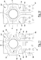
- the gripping elements 33 of an applying head 23 are movable between an engagement position P1, shown in Figures 6 and 8 , and a disengagement position P2, shown in Figures 5 and 7 .
- the engagement position P1 the gripping elements 33 are close to one another, so that the active surfaces 41 of the screwing portions 40 may interact with the appendages 6 of a lid 1 in order to rotate the lid 1 around the axis A of the neck 9.
- the gripping elements 33 are far from one another, so that the screwing portions 40 are arranged externally of the appendages 6 and cannot interact with the appendages 6.
- the gripping elements 33 move towards one another or away from one another along a direction that is perpendicular to the axis A of the neck 9.
- the guiding portions 37 slide in the seats of the supporting component 35, which keep the gripping elements 33 guided along their stroke from the engagement position P1 to the disengagement position P2 or vice versa.
- a pneumatic arrangement is provided for displacing the gripping elements 33 from the engagement position P1 to the disengagement position P2 or vice versa.
- the pneumatic arrangement comprises a pneumatic circuit inside which a pneumatic fluid, e.g. compressed air, may flow.
- the pneumatic circuit comprises a conduit defined inside the stem 36, which is hollow, such conduit being in fluid communication with a chamber obtained inside the supporting component 35. From this chamber, the pneumatic fluid acts on the guiding portions 37 of the gripping elements 33 in order to displace the gripping elements 33 between the engagement position P1 and the disengagement position P2.
- the driving device 34 moves the gripping elements 33 along a direction parallel to the axis A of a neck 9, towards the lid 1, until the abutment plane 38 abuts against the end wall 2 of the lid 1, as shown in Figure 7 . From this position, the gripping elements 33 move towards the lid 1 slightly more, so as to exert on the lid 1 a force directed towards the container 10, i.e. a compressing force, which allows the lid 1 to be positioned correctly on the neck 9.
- the gripping elements 33 thus exert a leveling action on the lid 1, in order to ensure that the end wall 2 of the lid 1 is perpendicular to the axis A of the neck 9, i.e. that the lid 1 is arranged coaxially to the neck 9.
- the lid 1 when the lid 1 is stripped by a container 10 in the distribution unit 21, the lid 1 is not correctly positioned onto the neck 9.
- the lid 1 might rest on the neck 9 in a tilted position, in which the axis A of the neck 9 is inclined relative to an axis of the neck 9.
- the containers 10 are not rigid containers, but are made of a flexible packaging sheet material and have dimensions varying within relatively large tolerances between different containers. Furthermore, the stiffness of the containers 10 is not as high as that of a glass bottle or jar. Consequently, the containers 10 need to be handled with care, to ensure that they are not damaged by the apparatus 20.
- the neck 9 may be relatively soft, particularly if moulded directly on the sheet packaging material. For this reason, the neck 9 might be slightly elliptical, instead of being perfectly circular.
- the compressing force applied by the gripping elements 33 on the lid 1 before starting to screw the lid 1 on the neck 9, may adapt the lid 1 to the neck 9, thereby enabling the lid 1 to be subsequently more easily screwed on the neck 9.
- the gripping elements 33 While the abutment plane 38 applies on the lid 1 the compression force that allows the lid 1 to be leveled on the neck 9, the gripping elements 33 are still in the disengagement position P2. After leveling the lid 1, the gripping elements 33 are moved one towards another by the pneumatic arrangement associated thereto, so that they can reach the engagement position P1.
- the gripping elements 33 might need to be rotated by a certain angle around the axis of the stem 36, so as to bring an active surface 41 of each screwing portion 40 in contact with an appendage 6 of the lid 1, as shown in Figure 8 .
- the screwing portions 40 are actually engaged with the appendages 6 and may effectively rotate the lid 1.
- the gripping elements 33 may initially rotate the lid 1 in a rotation direction that is opposite the rotation direction that allows the lid 1 to be screwed onto the neck 9, i.e. in an unscrewing direction, which is usually counterclockwise. This allows the lid 1 to be so positioned, that the starting point of an internal thread 4 on the lid 1 is aligned with the starting point of an outer thread 13 on the neck 9. This makes easier screwing the lid 1 onto the neck 9.
- the gripping elements 33 are now rotated in a screwing direction, and simultaneously moved towards the container 10, so that the lid 1 is screwed onto the neck 9.
- the lid 1 comprises the appendages 6, the lid 1 is rotated in the screwing direction until the appendages 6 have reached a preset position, particularly a preset angular position relative to the neck 9. At this point, the lid 1 is correctly screwed onto the neck 9 and can be released by the gripping elements 33.
- a position control that controls the position of the appendages 6 is used for determining the end of the screwing operation allowing the lid 1 to be screwed onto the neck 9.
- This position control is made possible by a position sensor, particularly an encoder, which is associated to the driving device 34.
- the sensor allows the angular position of the stem 36, and hence of the gripping elements 33, to be determined.
- the applying heads 23 may be configured to apply, onto the containers 10, lids 1 that do not comprise the appendages 6. i.e. lids 1 that are delimited by a cylindrical side wall 3.
- the gripping elements 33 act on the side wall 3 of the lid 1, i.e. grip directly a portion of cylindrical surface delimiting the lid 1 around its axis.
- the screwing action terminates when a preset screwing force has been applied onto the lid 1.
- the end of the screwing operation is determined by controlling the screwing force applied on the lid 1. This can be done by controlling the torque applied by the gripping elements 33 on the lid 1. It is thus possible to avoid damages on the lid 1 and/or on the neck 9 due to an excessive screwing force.
- the force applied onto the lid 1 while rotating the latter can be controlled easily and precisely, by controlling the pressure acting on the guiding portions 37 of the gripping elements 33.
- the apparatus 20 further comprises a plurality of welding heads 43 for induction welding the lid 1 to the protruding portion 17 that projects from the closing element 14.
- each welding head 43 is configured to generate in the conductive layer of the welding promoting element 7 an electric current, which melts the heat-sealable layer of the welding promoting element 7 facing the closing element 14. This heat-sealable layer thus adheres to the protruding portion 17, which consequently becomes permanently attached to the lid 1.
- the welding heads 43 are arranged downstream of the applying heads 23, along the conveying device that advances the containers 10 in the advancement direction F.
- the welding heads 43 thus interact with the containers 10 after the applying heads 23 have screwed the lids 1 onto the containers 10.
- the number of welding heads 43 may be equal to the number of applying heads 23. In the example shown, two welding heads 43 are provided, but this condition is not essential and the number of welding heads 43 could also be different from two.
- the distance between two consecutive welding heads 43 is equal to the distance between two consecutive containers 10 advancing along the advancement direction F. Similarly, the distance between the last applying head 23 and the first welding head 43 is equal to the distance between two consecutive containers 10.
- the welding heads 43 are movable forwards and backwards in the advancement direction F, i.e. are movable synchronously with the conveying device that advances the containers 10 in the advancement direction F, along a part of the path of the conveying device.
- each welding head 43 is capable of following a container 10 in order to interact with the corresponding lid 1 for a time sufficient to ensure welding of the lid 1 to the protruding portion 17.
- the welding head 43 moves backwards so as to reach an initial position in which it is ready to weld a new lid 1 to the corresponding container 10.
- All the welding heads 43 can be moved synchronously by a common mechanism. To this end, all the welding heads 43 can be supported by a common support member 44 so that, by moving the support member 44 in the advancement direction F, all the welding heads 43 are moved together in the advancing direction F forwards or backwards.
- the welding heads 43 are moved by the same movement device 26 that also displaces the applying heads 23.
- the support member 44 is fixed relative to the support element 24, for example because the support member 44 is directly fastened to the support element 24.
- the motor 27 moves the support element 24 by driving the belt 29, the support member 44, and consequently also the welding heads 43, are also displaced in the advancement direction F.
- the position of the applying heads 23, of the welding heads 43 and of the distribution unit 21 can be easily adjusted if, for example, there is the need to change the size and/or shape of the containers 10 to be processed.
- Figure 4 shows a frame 45 of the apparatus 20, which is fixed relative to the packaging line that processes the containers 10.
- the frame 45 comprises two end brackets 46, arranged at opposite sides of the apparatus 20.
- the distribution unit 21, the applying heads 23 and the welding heads 43 are supported by a common supporting arrangement that comprises, in addition to the support element 24 and the support member 44, a structure supporting the movement device 26 and a structure supporting the distribution unit 21.
- the common supporting arrangement comprises two supporting plates 49 each of which is fastened to an end bracket 46.
- the vertical position of the distribution unit 21 can be easily adjusted by vertically displacing the whole structure supporting the distribution unit 21, which is made possible by adjusting slots 50 provided in the supporting plate 49 adjacent to the distribution unit 21.
- the height of the distribution unit 21 above the conveying device that advances the containers 10 in the advancement direction F can therefore be adjusted.
- the vertical position of the applying module comprising the applying heads 23 and of the welding module comprising the welding heads 43 can be easily adjusted by means of few and simple adjustment operations.
- the support element 24 and the support member 44 are actually positioned in the supporting arrangement so that their height relative to the conveying device is adjustable.
- the apparatus 20 has high flexibility.
- FIG 10 shows in detail a welding head 43 acting on a lid 1 of a container 10.
- the welding head 43 comprises an electric induction generating element 51 including a coil that is not shown. By activating the coil, an electric current is induced in the conductive layer of the welding promoting element 7, with a consequent generation of localized heat causing the heat-sealable layer of the welding promoting element 7 facing the neck 9 to be welded to the protruding portion 17.
- the welding head 43 comprises an actuator device 52 for displacing the electric induction generating element 51 in a displacement direction arranged transversely, in particular perpendicularly, to the advancement direction F, so as to move the electric induction generating element 51 towards a lid 1 or alternatively away from a lid 1. More precisely, the actuator device 52 is intended to move the electric induction generating element 51 parallelly to the axis of the lid 1 that is being welded.
- the actuator device 52 may comprise for example an electric linear motor or a pneumatic actuator.
- the actuator device 52 is configured to displace the electric induction generating element 51 between an active configuration C1, shown for example in Figure 10 , and an inactive configuration C2, shown in Figure 4 .
- the electric induction generating element 51 is at a distance from the lid 1, so as not to interact with the latter.
- the electric induction generating element 51 interacts with the lid 1 and welds the latter to the protruding portion 17.
- the electric induction generating element 51 is in contact with the end wall 2 of the lid 1 in the active configuration C1.
- the electric induction generation element 51 may nevertheless weld the lid 1 to the protruding portion 17 by remaining at a short distance from the end wall 2 in the active configuration C1.
- Each welding head 43 further comprises a pair of gripping members 53 for gripping the lid 1, particularly at the side wall 3 thereof, so as to avoid undesired side displacements of the lid 1 during welding.
- each gripping member 53 comprises an interaction portion 54 for interacting with the lid 1.
- the interaction portion 54 of a gripping member 53 is delimited by two contact surfaces 55 for contacting the side wall 3 of the lid 1.
- the contact surfaces 55 are substantially flat.
- the contact surfaces 55 of a gripping member 53 define respective planes that are perpendicular to one another.
- the gripping members 53 of a welding head 43 are symmetrical with respect to one another.
- the four contact surfaces 55 of the two interacting gripping members 53 lie in respective planes that are arranged at right angles one to another, thereby defining an ideal square, in plan view.
- each contact surfaces 55 of a pair of gripping members 53 lies in a respective plane parallel to the axis of a lid 1.
- a recess 56 is provided in the interacting portion 54.
- the recess 56 has the purpose of housing an appendage 6 of a lid 1 while the lid 1 is gripped by the gripping members 53.
- the gripping members 53 of a welding head 43 are movable between an open position Q1, shown in Figure 11 , and a closed position Q2, shown in Figure 12 .
- the open position Q1 the gripping members 53 are far away from one another and do not interact with a lid 1.
- the closed position Q2 the gripping members 53 are closer to one another, so as to hold a lid 1 between the contact surfaces 55.
- each welding head 43 further comprises a carrying element 57 for supporting the gripping members 53.
- the carrying element 57 may be arranged in a back region of the welding head 43.
- Each gripping member 53 comprises a guiding part 58 that is slidingly coupled to the carrying element 57.
- the guiding part 58 may be for example T-shaped and engages in a correspondingly shaped seat of the carrying element 57, so as to be guided by the carrying element 57 when the gripping members 53 move between the open position Q1 and the closed position Q2.
- Each gripping member 53 further comprises an intermediate portion 59 that connects the interaction portion 54 to the guiding part 58.
- a pneumatic system for displacing the gripping members 53 between the open position Q1 and the closed position Q2.
- the pneumatic system comprises a pneumatic circuit inside which a pneumatic fluid, e.g. compressed air, may flow.
- the pneumatic circuit comprises a chamber obtained inside the carrying element 57. From this chamber, the pneumatic fluid acts on the guiding parts 58 of the gripping members 53 in order to displace the gripping members 53 between the open position Q1 and the closed position Q2.
- the carrying element 57 is fastened to a mounting component 60 arranged above the electric induction generating element 51.
- Each welding head 43 further comprises a compensating device 62 that allows the electric inducting generating element 51 to be centered relative to the end wall 2 of the lid 1, by compensating a possible misalignment between the electric inducting generating element 51 and the lid 1.
- the compensating device 62 is interposed between the actuator device 52 and the electric inductive generating element 51.
- the compensating device 62 comprises a first component 63 that is fixed relative to the actuator device 52.
- the first component 63 is fixed relative to a plate 64 of the actuator device 52.
- the plate 64 is in turn connected to a plurality of columns 65 of the actuator device 52, the columns 65 being slidable relative to a main body 66 of the actuator device 52 when the actuator device 52 moves the gripping members 53 between the active configuration C1 and the inactive configuration C2.
- the compensating device 62 further comprises a second component 67 coupled to the first component 63.
- the coupling between the first component 63 and the second component 67 has two degrees of freedom, since the second component 67 is capable of sliding in two directions relative to the first component 63. More precisely, the first component 63 and the second component 67 are in contact to one another in an interface plane P and the second component 67 is capable of sliding in the interface plane P relative to the first component 63.
- the interface plane P is parallel to a flat surface of the electric induction generating element 51, said flat surface being intended to contact the end wall 2 of the lid 1.
- the interface plane P is arranged transversely, in particular perpendicularly, to the displacement direction along which the actuator device 52 displaces the electric induction generating element 51 when moving the latter between the active configuration C1 and the inactive configuration C2.
- the interface plane P is arranged transversely, in particular perpendicularly, to the axis A of the neck 9. In other words, the interface plane P is parallel to the end wall 2 of the lid 1 and also to a top wall of the container 10.
- the second component 67 is closer to the electric induction generating element 51 than the first component 63. In other words, the second component 67 faces towards the electric induction generating element 51, whereas the first component 63 faces away from the electric induction generating element 51.
- the electric induction generating element 51 is fixed relative to the second component 67 as far as displacement in a plane parallel to the interface plane P is concerned.
- the electric induction generating element 51 is first brought in the active configuration C1.
- the gripping members 53 are still in the open position Q1, as shown in Figure 5 .
- the gripping members 53 are then brought into the closed position Q2 by the pneumatic system associated thereto. It may happen that the cap 1 is not perfectly centered relative to the electric induction generating element 51 and hence relative to the gripping members 53. If this occurs, a center of the end wall 2 of the lid 1 is not coincident with a central point of an ideal quadrilateral defined by the contact surfaces 55.
- the side wall 3 of the lid 1 contacts one of the contact surfaces 55 before contacting the other three contact surfaces 55.
- the second component 67 of the compensating device 62 moves parallelly to the interface plane P, i.e. parallelly to the end wall 2 of the lid 1, in order to compensate such contact force.
- the electric induction generating element 51 moves together with the second component 67, thereby reaching a position in which the gripping members 53, and hence also the electric induction generating element 51, are centered relative to the lid 1.
- the gripping members 53 exert a guiding action on the second component 67 of the compensating device 62, and consequently on the electric induction generating element 51.
- the lid 1 determines the position of the gripping members 53, which in turn determine the position of the second component 67, thereby allowing the electric induction generating element 51 to be centered relative to the lid 1.
- the gripping members 53 are associated with the second component 67, particularly by means of the carrying element 58, which is fixed relative to the second component 67 as far as displacement parallelly to the interface plane P is concerned.
- the electric induction generating element 51 may correctly weld the end wall 2 of the lid 1 to the protruding portion 17.
- the containers 10 are arranged in a sequence at a preset distance from one another by a sequencing device that is not shown.
- the containers 10 are then advanced along the advancement direction F so as to pass below the distribution unit 21.
- each container 10 receives a lid 1, which rests on the neck 9 without being fully applied to the latter.
- the lid 1 may be released in a random angular position on the neck 9, i.e. the distribution unit 21 may be so configured that a position control on the angular position of the lids 1 is not applied.
- each gripping head 23 which are still in the disengagement position P2, as shown in Figure 5 , apply a compressing force on the respective lid 1, i.e. push the lid 1 towards the neck 9. This allows the lid 1 to be leveled on the neck 9, i.e. to be positioned on the neck 9 with the top wall 2 substantially perpendicular to the axis of the neck 9.
- each applying head 23 The gripping elements 33 of each applying head 23 are then moved into the engagement position P1, as shown in Figure 6 , and the lid 1 is initially rotated in an unscrewing direction so that its internal thread 4 engages with the outer thread 13 of the neck 9. Thereafter, the lid 1 is rotated in a screwing direction, so as to be screwed onto the neck 9, until a predetermined angular position of the lid 1, or a predetermined screwing force, has been reached.
- each applying head 23 When the lids 1 have been completely screwed onto the necks 9, the gripping elements 33 of each applying head 23 are opened to reach the disengagement position P2, and are displaced upwards in order to disengage from the corresponding lid 1, as shown in Figure 9 .
- the movement device 26 now displaces the applying heads 23 backwards, so that the applying heads 23 can engage with a new group of containers 10.
- the containers 10 on which the lids 1 have been applied continue to move along the advancement direction F towards the welding heads 43, so as to arrive below the welding heads 43.
- Each welding head 43 is then displaced downwards, until the respective electric induction generating element 31 contacts the end wall 2 of a lid 1 in the active configuration C1.
- the gripping members 53 are in the open position Q1, as shown in Figures 5 and 9 .
- the gripping members 53 of each welding head 43 are brought into the closed position Q2, as shown in Figure 6 .
- the side wall 3 of the lid 1 is contacted by at least one contact surface 55 of a gripping member 53.
- the compensating device 62 allows the electric induction generating element 51 to move in a plane perpendicular to the end wall 2 of the lid 1, so as to reach a centered position relative to the lid 1.
- the lid 1 may now be welded to the protruding portion 17 of the closing element 14, owing to the welding promoting element 7.
- the movement device 26 moves the support member 44 along the advancement direction F, which causes the welding heads 43, which are fixed relative to the support member 44, to be moved together, i.e. synchronously, along the advancement direction F.
- the gripping members 53 are opened and move away from the corresponding lid 1, which is thus released from the welding head 43.
- the welding heads 43 supported by the support member 44 are moved backwards by the movement device 26, so as to reach a position in which the welding heads 43 may engage with a new group of containers 10.
- the apparatus 20 may be used to apply, onto the necks 9, lids 1 that are substantially round, i.e. that do not possess the appendages 6.
- the gripping elements 33 and the gripping members 53 may have a simpler structure and be configured to engage directly with the side wall 3 of the lids 1.
- the apparatus 20, and particularly the welding heads 43 thereof allow the lids 1 to be reliably and effectively welded to the opening devices provided on the containers 10, and particularly to the protruding portions 17, even at high production rates.
- the gripping elements 33 and the gripping members 53 can be shaped as desired, thereby allowing also non-round lids 1 to be applied.
Claims (14)
- Tête de soudage comprenant un élément de soudage (51) pour souder un couvercle (1) à un dispositif d'ouverture d'un contenant (10) et un dispositif de compensation (62) utilisable pour compenser un désalignement entre l'élément de soudage (51) et le couvercle (1), ainsi centrant l'élément de soudage (51) relativement au couvercle (1), caractérisé en ce que le dispositif de compensation (62) est configuré pour permettre à l'élément de soudage (51) de coulisser dans un plan qui, durant l'utilisation, est agencé transversalement, en particulier perpendiculairement, à un axe du couvercle (1).
- Tête de soudage selon la revendication 1, dans laquelle le dispositif de compensation (62) comprend un premier composant (63) tourné à l'opposé de l'élément de soudage (51) et un second composant (67) tourné vers l'élément de soudage (51), le premier composant (63) interagissant avec le second composant (67) dans un plan d'interface (P), le second composant (67) pouvant coulisser parallèlement au plan d'interface (P) relativement au premier composant (63).
- Tête de soudage selon la revendication 2, dans laquelle l'élément de soudage (51) est supporté par le second composant (67).
- Tête de soudage selon la revendication 2 ou 3, dans laquelle la tête de soudage (43) comprend au moins deux organes de préhension (53) pour retenir le couvercle (1) durant le soudage, les organes de préhension (53) étant associés au second composant (67) afin de positionner le second composant (67) en fonction de la position d'un couvercle (1) destiné à être soudé.
- Tête de soudage selon la revendication 4, dans laquelle les organes de préhension (53) sont supportés par un élément de support (57) qui est fixe relativement au second composant (67) en ce qui concerne le déplacement parallèlement au plan d'interface (P).
- Tête de soudage selon la revendication 5, dans laquelle chaque organe de préhension (53) comprend une partie de guidage (58) qui s'engage de façon coulissante dans un siège correspondant réalisé sur l'élément de support (57), pour que les organes de préhension (53) soient mobiles entre une position ouverte (Q1), dans laquelle les organes de préhension (53) n'interagissent pas avec le couvercle (1), et une position fermée (Q2), dans laquelle les organes de préhension (53) retiennent le couvercle (1).
- Tête de soudage selon l'une quelconque des revendications 4 à 6, dans laquelle les organes de préhension (53) comprennent une pluralité de surfaces de contact (55) pour entrer en contact avec des portions distinctes d'une paroi latérale (3) du couvercle (1), moyennant quoi la surface de contact (55) de ladite pluralité qui entre en contact en premier avec la paroi latérale (3) du couvercle (1) détermine la position des organes de préhension (53) parallèlement au plan d'interface (P) .
- Tête de soudage selon la revendication 7, dans laquelle ladite pluralité de surfaces de contact (55) comprend au moins deux surfaces de contact (55) prévues sur un des organes de préhension (53) et au moins deux surfaces de contact supplémentaires (55) prévues sur un autre des organes de préhension (53).
- Tête de soudage selon la revendication 8, dans laquelle un évidement (56) est prévu entre les surfaces de contact (55) d'un organe de préhension (53), ledit évidement (56) étant configuré pour loger un appendice (6) faisant saillie à partir de la paroi latérale (3) du couvercle (1).
- Tête de soudage selon la revendication 8 ou 9, dans laquelle chaque surface de contact (55) définit un plan, les plans définis par deux surfaces de contact adjacentes (55) étant agencés à angle droit.
- Tête de soudage selon une quelconque revendication précédente, et comprenant en outre un dispositif actionneur (52) pour déplacer l'élément de soudage (51) dans une direction de déplacement, entre une configuration active (C1), dans laquelle l'élément de soudage (51) est plus près d'une paroi d'extrémité (2) du couvercle (1) pour souder la paroi d'extrémité (2) au dispositif d'ouverture, et une configuration inactive (C2), dans laquelle l'élément de soudage (51) est plus éloigné de la paroi d'extrémité (2) afin de ne pas interagir avec le couvercle (1).
- Tête de soudage selon la revendication 11, telle qu'annexée à l'une quelconque des revendications 2 à 10, dans laquelle le second composant (67) est fixe relativement à une plaque mobile (64) du dispositif actionneur (52).
- Tête de soudage selon la revendication 12, ou selon la revendication 11, telle qu'annexée à l'une quelconque des revendications 2 à 10, dans laquelle la direction de déplacement est agencée transversalement, en particulier perpendiculairement, au plan d'interface (P).
- Tête de soudage selon une quelconque revendication précédente, dans laquelle l'élément de soudage comprend un élément de génération d'induction électrique (51) pour générer un courant électrique capable de thermosceller le couvercle (1) sur le dispositif d'ouverture.
Priority Applications (8)
| Application Number | Priority Date | Filing Date | Title |
|---|---|---|---|
| EP15188370.9A EP3153304B1 (fr) | 2015-10-05 | 2015-10-05 | Tête de soudage |
| PCT/EP2016/072124 WO2017060061A1 (fr) | 2015-10-05 | 2016-09-19 | Tête de soudage |
| BR112018002088A BR112018002088A2 (pt) | 2015-10-05 | 2016-09-19 | cabeça de soldagem |
| MX2018001791A MX2018001791A (es) | 2015-10-05 | 2016-09-19 | Cabeza de soldadura. |
| US15/765,881 US10919234B2 (en) | 2015-10-05 | 2016-09-19 | Welding head |
| JP2018517630A JP6913677B2 (ja) | 2015-10-05 | 2016-09-19 | 溶着ヘッド |
| CN201680047925.9A CN107921715B (zh) | 2015-10-05 | 2016-09-19 | 一种焊头 |
| RU2018114667A RU2018114667A (ru) | 2015-10-05 | 2016-09-19 | Сварочная головка |
Applications Claiming Priority (1)
| Application Number | Priority Date | Filing Date | Title |
|---|---|---|---|
| EP15188370.9A EP3153304B1 (fr) | 2015-10-05 | 2015-10-05 | Tête de soudage |
Publications (2)
| Publication Number | Publication Date |
|---|---|
| EP3153304A1 EP3153304A1 (fr) | 2017-04-12 |
| EP3153304B1 true EP3153304B1 (fr) | 2019-12-11 |
Family
ID=54266418
Family Applications (1)
| Application Number | Title | Priority Date | Filing Date |
|---|---|---|---|
| EP15188370.9A Active EP3153304B1 (fr) | 2015-10-05 | 2015-10-05 | Tête de soudage |
Country Status (8)
| Country | Link |
|---|---|
| US (1) | US10919234B2 (fr) |
| EP (1) | EP3153304B1 (fr) |
| JP (1) | JP6913677B2 (fr) |
| CN (1) | CN107921715B (fr) |
| BR (1) | BR112018002088A2 (fr) |
| MX (1) | MX2018001791A (fr) |
| RU (1) | RU2018114667A (fr) |
| WO (1) | WO2017060061A1 (fr) |
Families Citing this family (4)
| Publication number | Priority date | Publication date | Assignee | Title |
|---|---|---|---|---|
| JP7224344B2 (ja) * | 2017-09-18 | 2023-02-17 | テトラ ラバル ホールディングス アンド ファイナンス エス エイ | 溶接ヘッド |
| CN111284781A (zh) * | 2020-03-12 | 2020-06-16 | 周建平 | 一种基于光感控制的塑料包装焊接可自动定高焊接的装置 |
| CN111976148A (zh) * | 2020-08-18 | 2020-11-24 | 严雨琴 | 高频塑料热合机 |
| WO2024002832A1 (fr) * | 2022-06-30 | 2024-01-04 | Tetra Laval Holdings & Finance S.A. | Dispositif d'ouverture pour emballage, et emballage pourvu de celui-ci |
Family Cites Families (37)
| Publication number | Priority date | Publication date | Assignee | Title |
|---|---|---|---|---|
| US2422750A (en) * | 1943-06-05 | 1947-06-24 | Pabst Brewing Co | Plastic bottle crowner |
| US3460310A (en) * | 1964-12-09 | 1969-08-12 | United Glass Ltd | Container closures |
| NL7112926A (fr) * | 1971-09-21 | 1973-03-23 | ||
| US3928109A (en) * | 1972-09-11 | 1975-12-23 | Phoenix Closures Inc | Method of assembling and bonding a laminated liner within a closure member |
| FR2199527B1 (fr) * | 1972-09-15 | 1975-03-14 | Stel | |
| US3783582A (en) * | 1972-11-30 | 1974-01-08 | E Willvonseder | Shrink-film capping machine |
| US3909326A (en) * | 1973-02-26 | 1975-09-30 | Kraftco Corp | Method for applying heat sealable membrane |
| US3946540A (en) * | 1974-05-13 | 1976-03-30 | Champion International Corporation | Heat seal capper head assembly |
| US4265696A (en) * | 1979-09-05 | 1981-05-05 | Universal Precision Machining Co. | Apparatus for heat sealing |
| GB8721663D0 (en) * | 1987-09-15 | 1987-10-21 | Electricity Council | Induction heating apparatus |
| JP2711467B2 (ja) * | 1989-01-26 | 1998-02-10 | 島田理化工業株式会社 | 筒状容器の高周波溶着装置 |
| US5858141A (en) * | 1990-08-09 | 1999-01-12 | Portola Packaging, Inc. | Method and apparatus to attach foil seals to necks |
| US5284001A (en) * | 1992-10-16 | 1994-02-08 | Anchor Hocking Packaging Co. | Spindle type straight line capper |
| JPH1033636A (ja) * | 1996-05-03 | 1998-02-10 | Yuyama Seisakusho:Kk | 薬剤分包装置、薬瓶及び薬剤検査方法 |
| US6412252B1 (en) * | 1996-11-15 | 2002-07-02 | Kaps-All Packaging Systems, Inc. | Slotted induction heater |
| US6747252B2 (en) * | 1996-11-15 | 2004-06-08 | Kenneth J. Herzog | Multiple head induction sealer apparatus and method |
| DE19707007A1 (de) | 1997-02-21 | 1998-08-27 | Alfelder Kunststoffw Meyer H | Vorrichtung und Verfahren zur Induktionsversiegelung |
| US6104013A (en) * | 1998-01-16 | 2000-08-15 | Miller; Cardell | Induction sealing covers with tabs |
| US6079185A (en) * | 1998-07-31 | 2000-06-27 | Tetra Laval Holdings & Finance, Sa | Induction heat sealing of a closure to a container |
| FR2802176B1 (fr) * | 1999-12-09 | 2002-01-18 | Ducros | Procede et dispositif pour conditionner un solide, notamment alimentaire, dans un recipient tel que flacon |
| US20040035088A1 (en) * | 2002-06-10 | 2004-02-26 | Loeffler Herbert H. | Container positioning device |
| DE10328411B4 (de) * | 2002-11-29 | 2005-04-14 | Sig Technology Ltd. | Vorrichtung zum Einsiegeln eines Deckelelementes in einen Mantelteil eines Verpackungskörpers aus Verbundmaterial |
| US7322160B2 (en) * | 2004-05-17 | 2008-01-29 | Herzog Kenneth J | Monitoring system for induction sealer |
| DE202007003450U1 (de) * | 2007-03-06 | 2007-05-10 | Hüttinger Elektronik Gmbh + Co. Kg | Flexibler Induktor für das induktive Versiegeln von Gebinden |
| EP1967452B1 (fr) * | 2007-03-06 | 2010-01-27 | HÜTTINGER Elektronik GmbH + Co. KG | Inducteur flexible pour le scellage inductif de fûts |
| ITBO20070546A1 (it) * | 2007-08-02 | 2009-02-03 | Acma Spa | Apparecchiatura di presa per gruppi tappatori in macchine per il confezionamento di contenitori. |
| US7834298B2 (en) * | 2007-11-26 | 2010-11-16 | Ultraflex International, Inc. | Adjustable electromagnetic sealing device |
| CN101559547B (zh) * | 2009-04-09 | 2011-04-20 | 上海交通大学 | 适用于超声纳米焊接中焊头与样品的平行度调节方法 |
| EP2495176B1 (fr) * | 2011-03-03 | 2013-08-21 | UHLMANN PAC-SYSTEME GmbH & Co. KG | Dispositif destiné à fermer des récipients |
| ES2610911T3 (es) * | 2011-07-11 | 2017-05-04 | A&R Carton Lund AB | Aparato y procedimiento para cerrar de forma estanca un recipiente a base de cartón |
| US10131455B2 (en) * | 2011-10-28 | 2018-11-20 | Sonoco Development, Inc. | Apparatus and method for induction sealing of conveyed workpieces |
| US20140290181A1 (en) * | 2013-04-01 | 2014-10-02 | Bottle Tree Water Corporation | System and Method for Eco-Friendly Beverage Dispensing Kiosk |
| CN103521908B (zh) * | 2013-09-29 | 2015-09-23 | 常州市瑞泰工程机械有限公司 | 型材感应焊装置及方法 |
| WO2015121838A2 (fr) * | 2014-02-13 | 2015-08-20 | G.D Societa' Per Azioni | Unité d'application et procédé d'application d'une paroi à un corps creux dans un processus de fabrication pour produire une capsule de boisson |
| FR3022222B1 (fr) * | 2014-06-17 | 2019-04-12 | 1/4 Vin | Procede et dispositif de thermoscellage d'un opercule sur le buvant d'un verre |
| US9808883B2 (en) * | 2014-12-05 | 2017-11-07 | T.A. Systems, Inc. | Dual ultrasonic welder |
| CN204417073U (zh) * | 2014-12-10 | 2015-06-24 | 江西科伦药业有限公司 | 焊盖机 |
-
2015
- 2015-10-05 EP EP15188370.9A patent/EP3153304B1/fr active Active
-
2016
- 2016-09-19 US US15/765,881 patent/US10919234B2/en active Active
- 2016-09-19 RU RU2018114667A patent/RU2018114667A/ru not_active Application Discontinuation
- 2016-09-19 JP JP2018517630A patent/JP6913677B2/ja active Active
- 2016-09-19 WO PCT/EP2016/072124 patent/WO2017060061A1/fr active Application Filing
- 2016-09-19 MX MX2018001791A patent/MX2018001791A/es unknown
- 2016-09-19 BR BR112018002088A patent/BR112018002088A2/pt not_active Application Discontinuation
- 2016-09-19 CN CN201680047925.9A patent/CN107921715B/zh active Active
Non-Patent Citations (1)
| Title |
|---|
| None * |
Also Published As
| Publication number | Publication date |
|---|---|
| JP6913677B2 (ja) | 2021-08-04 |
| MX2018001791A (es) | 2018-06-06 |
| JP2018531164A (ja) | 2018-10-25 |
| CN107921715B (zh) | 2021-03-12 |
| WO2017060061A1 (fr) | 2017-04-13 |
| US20180297294A1 (en) | 2018-10-18 |
| EP3153304A1 (fr) | 2017-04-12 |
| BR112018002088A2 (pt) | 2018-09-18 |
| US10919234B2 (en) | 2021-02-16 |
| CN107921715A (zh) | 2018-04-17 |
| RU2018114667A (ru) | 2019-11-07 |
Similar Documents
| Publication | Publication Date | Title |
|---|---|---|
| US10815017B2 (en) | Apparatus for capping a container | |
| US10351286B2 (en) | Applying unit for applying a lid onto a container | |
| US11242167B2 (en) | Welding head | |
| US10919234B2 (en) | Welding head | |
| US10967996B2 (en) | Method of, and an applying head for, applying a lid onto a container | |
| JP2018531164A6 (ja) | 溶着ヘッド | |
| US11186392B2 (en) | Distribution unit for feeding lids to necks of containers |
Legal Events
| Date | Code | Title | Description |
|---|---|---|---|
| PUAI | Public reference made under article 153(3) epc to a published international application that has entered the european phase |
Free format text: ORIGINAL CODE: 0009012 |
|
| STAA | Information on the status of an ep patent application or granted ep patent |
Free format text: STATUS: THE APPLICATION HAS BEEN PUBLISHED |
|
| AK | Designated contracting states |
Kind code of ref document: A1 Designated state(s): AL AT BE BG CH CY CZ DE DK EE ES FI FR GB GR HR HU IE IS IT LI LT LU LV MC MK MT NL NO PL PT RO RS SE SI SK SM TR |
|
| AX | Request for extension of the european patent |
Extension state: BA ME |
|
| STAA | Information on the status of an ep patent application or granted ep patent |
Free format text: STATUS: REQUEST FOR EXAMINATION WAS MADE |
|
| 17P | Request for examination filed |
Effective date: 20171012 |
|
| RBV | Designated contracting states (corrected) |
Designated state(s): AL AT BE BG CH CY CZ DE DK EE ES FI FR GB GR HR HU IE IS IT LI LT LU LV MC MK MT NL NO PL PT RO RS SE SI SK SM TR |
|
| REG | Reference to a national code |
Ref country code: DE Ref legal event code: R079 Ref document number: 602015043355 Country of ref document: DE Free format text: PREVIOUS MAIN CLASS: B29C0065780000 Ipc: B29C0065360000 |
|
| GRAP | Despatch of communication of intention to grant a patent |
Free format text: ORIGINAL CODE: EPIDOSNIGR1 |
|
| STAA | Information on the status of an ep patent application or granted ep patent |
Free format text: STATUS: GRANT OF PATENT IS INTENDED |
|
| RIC1 | Information provided on ipc code assigned before grant |
Ipc: B29C 65/48 20060101ALN20190708BHEP Ipc: B29C 65/36 20060101AFI20190708BHEP Ipc: B29C 65/78 20060101ALI20190708BHEP Ipc: B65B 7/28 20060101ALI20190708BHEP Ipc: B29C 65/56 20060101ALN20190708BHEP Ipc: B29K 705/02 20060101ALN20190708BHEP Ipc: B29C 65/50 20060101ALN20190708BHEP Ipc: B65B 7/16 20060101ALI20190708BHEP Ipc: B65B 51/22 20060101ALI20190708BHEP |
|
| INTG | Intention to grant announced |
Effective date: 20190805 |
|
| GRAS | Grant fee paid |
Free format text: ORIGINAL CODE: EPIDOSNIGR3 |
|
| GRAA | (expected) grant |
Free format text: ORIGINAL CODE: 0009210 |
|
| STAA | Information on the status of an ep patent application or granted ep patent |
Free format text: STATUS: THE PATENT HAS BEEN GRANTED |
|
| AK | Designated contracting states |
Kind code of ref document: B1 Designated state(s): AL AT BE BG CH CY CZ DE DK EE ES FI FR GB GR HR HU IE IS IT LI LT LU LV MC MK MT NL NO PL PT RO RS SE SI SK SM TR |
|
| REG | Reference to a national code |
Ref country code: GB Ref legal event code: FG4D |
|
| REG | Reference to a national code |
Ref country code: CH Ref legal event code: EP |
|
| REG | Reference to a national code |
Ref country code: AT Ref legal event code: REF Ref document number: 1211759 Country of ref document: AT Kind code of ref document: T Effective date: 20191215 |
|
| REG | Reference to a national code |
Ref country code: DE Ref legal event code: R096 Ref document number: 602015043355 Country of ref document: DE |
|
| REG | Reference to a national code |
Ref country code: IE Ref legal event code: FG4D |
|
| REG | Reference to a national code |
Ref country code: NL Ref legal event code: MP Effective date: 20191211 |
|
| REG | Reference to a national code |
Ref country code: LT Ref legal event code: MG4D |
|
| PG25 | Lapsed in a contracting state [announced via postgrant information from national office to epo] |
Ref country code: LT Free format text: LAPSE BECAUSE OF FAILURE TO SUBMIT A TRANSLATION OF THE DESCRIPTION OR TO PAY THE FEE WITHIN THE PRESCRIBED TIME-LIMIT Effective date: 20191211 Ref country code: NO Free format text: LAPSE BECAUSE OF FAILURE TO SUBMIT A TRANSLATION OF THE DESCRIPTION OR TO PAY THE FEE WITHIN THE PRESCRIBED TIME-LIMIT Effective date: 20200311 Ref country code: GR Free format text: LAPSE BECAUSE OF FAILURE TO SUBMIT A TRANSLATION OF THE DESCRIPTION OR TO PAY THE FEE WITHIN THE PRESCRIBED TIME-LIMIT Effective date: 20200312 Ref country code: FI Free format text: LAPSE BECAUSE OF FAILURE TO SUBMIT A TRANSLATION OF THE DESCRIPTION OR TO PAY THE FEE WITHIN THE PRESCRIBED TIME-LIMIT Effective date: 20191211 Ref country code: BG Free format text: LAPSE BECAUSE OF FAILURE TO SUBMIT A TRANSLATION OF THE DESCRIPTION OR TO PAY THE FEE WITHIN THE PRESCRIBED TIME-LIMIT Effective date: 20200311 Ref country code: LV Free format text: LAPSE BECAUSE OF FAILURE TO SUBMIT A TRANSLATION OF THE DESCRIPTION OR TO PAY THE FEE WITHIN THE PRESCRIBED TIME-LIMIT Effective date: 20191211 Ref country code: SE Free format text: LAPSE BECAUSE OF FAILURE TO SUBMIT A TRANSLATION OF THE DESCRIPTION OR TO PAY THE FEE WITHIN THE PRESCRIBED TIME-LIMIT Effective date: 20191211 |
|
| PG25 | Lapsed in a contracting state [announced via postgrant information from national office to epo] |
Ref country code: RS Free format text: LAPSE BECAUSE OF FAILURE TO SUBMIT A TRANSLATION OF THE DESCRIPTION OR TO PAY THE FEE WITHIN THE PRESCRIBED TIME-LIMIT Effective date: 20191211 Ref country code: HR Free format text: LAPSE BECAUSE OF FAILURE TO SUBMIT A TRANSLATION OF THE DESCRIPTION OR TO PAY THE FEE WITHIN THE PRESCRIBED TIME-LIMIT Effective date: 20191211 |
|
| PG25 | Lapsed in a contracting state [announced via postgrant information from national office to epo] |
Ref country code: AL Free format text: LAPSE BECAUSE OF FAILURE TO SUBMIT A TRANSLATION OF THE DESCRIPTION OR TO PAY THE FEE WITHIN THE PRESCRIBED TIME-LIMIT Effective date: 20191211 |
|
| PG25 | Lapsed in a contracting state [announced via postgrant information from national office to epo] |
Ref country code: PT Free format text: LAPSE BECAUSE OF FAILURE TO SUBMIT A TRANSLATION OF THE DESCRIPTION OR TO PAY THE FEE WITHIN THE PRESCRIBED TIME-LIMIT Effective date: 20200506 Ref country code: ES Free format text: LAPSE BECAUSE OF FAILURE TO SUBMIT A TRANSLATION OF THE DESCRIPTION OR TO PAY THE FEE WITHIN THE PRESCRIBED TIME-LIMIT Effective date: 20191211 Ref country code: CZ Free format text: LAPSE BECAUSE OF FAILURE TO SUBMIT A TRANSLATION OF THE DESCRIPTION OR TO PAY THE FEE WITHIN THE PRESCRIBED TIME-LIMIT Effective date: 20191211 Ref country code: RO Free format text: LAPSE BECAUSE OF FAILURE TO SUBMIT A TRANSLATION OF THE DESCRIPTION OR TO PAY THE FEE WITHIN THE PRESCRIBED TIME-LIMIT Effective date: 20191211 Ref country code: NL Free format text: LAPSE BECAUSE OF FAILURE TO SUBMIT A TRANSLATION OF THE DESCRIPTION OR TO PAY THE FEE WITHIN THE PRESCRIBED TIME-LIMIT Effective date: 20191211 Ref country code: EE Free format text: LAPSE BECAUSE OF FAILURE TO SUBMIT A TRANSLATION OF THE DESCRIPTION OR TO PAY THE FEE WITHIN THE PRESCRIBED TIME-LIMIT Effective date: 20191211 |
|
| PG25 | Lapsed in a contracting state [announced via postgrant information from national office to epo] |
Ref country code: SK Free format text: LAPSE BECAUSE OF FAILURE TO SUBMIT A TRANSLATION OF THE DESCRIPTION OR TO PAY THE FEE WITHIN THE PRESCRIBED TIME-LIMIT Effective date: 20191211 Ref country code: IS Free format text: LAPSE BECAUSE OF FAILURE TO SUBMIT A TRANSLATION OF THE DESCRIPTION OR TO PAY THE FEE WITHIN THE PRESCRIBED TIME-LIMIT Effective date: 20200411 Ref country code: SM Free format text: LAPSE BECAUSE OF FAILURE TO SUBMIT A TRANSLATION OF THE DESCRIPTION OR TO PAY THE FEE WITHIN THE PRESCRIBED TIME-LIMIT Effective date: 20191211 |
|
| REG | Reference to a national code |
Ref country code: DE Ref legal event code: R097 Ref document number: 602015043355 Country of ref document: DE |
|
| REG | Reference to a national code |
Ref country code: AT Ref legal event code: MK05 Ref document number: 1211759 Country of ref document: AT Kind code of ref document: T Effective date: 20191211 |
|
| PLBE | No opposition filed within time limit |
Free format text: ORIGINAL CODE: 0009261 |
|
| STAA | Information on the status of an ep patent application or granted ep patent |
Free format text: STATUS: NO OPPOSITION FILED WITHIN TIME LIMIT |
|
| PG25 | Lapsed in a contracting state [announced via postgrant information from national office to epo] |
Ref country code: DK Free format text: LAPSE BECAUSE OF FAILURE TO SUBMIT A TRANSLATION OF THE DESCRIPTION OR TO PAY THE FEE WITHIN THE PRESCRIBED TIME-LIMIT Effective date: 20191211 |
|
| 26N | No opposition filed |
Effective date: 20200914 |
|
| PG25 | Lapsed in a contracting state [announced via postgrant information from national office to epo] |
Ref country code: SI Free format text: LAPSE BECAUSE OF FAILURE TO SUBMIT A TRANSLATION OF THE DESCRIPTION OR TO PAY THE FEE WITHIN THE PRESCRIBED TIME-LIMIT Effective date: 20191211 Ref country code: AT Free format text: LAPSE BECAUSE OF FAILURE TO SUBMIT A TRANSLATION OF THE DESCRIPTION OR TO PAY THE FEE WITHIN THE PRESCRIBED TIME-LIMIT Effective date: 20191211 |
|
| PG25 | Lapsed in a contracting state [announced via postgrant information from national office to epo] |
Ref country code: PL Free format text: LAPSE BECAUSE OF FAILURE TO SUBMIT A TRANSLATION OF THE DESCRIPTION OR TO PAY THE FEE WITHIN THE PRESCRIBED TIME-LIMIT Effective date: 20191211 |
|
| REG | Reference to a national code |
Ref country code: CH Ref legal event code: PL |
|
| GBPC | Gb: european patent ceased through non-payment of renewal fee |
Effective date: 20201005 |
|
| PG25 | Lapsed in a contracting state [announced via postgrant information from national office to epo] |
Ref country code: LU Free format text: LAPSE BECAUSE OF NON-PAYMENT OF DUE FEES Effective date: 20201005 Ref country code: MC Free format text: LAPSE BECAUSE OF FAILURE TO SUBMIT A TRANSLATION OF THE DESCRIPTION OR TO PAY THE FEE WITHIN THE PRESCRIBED TIME-LIMIT Effective date: 20191211 |
|
| REG | Reference to a national code |
Ref country code: BE Ref legal event code: MM Effective date: 20201031 |
|
| PG25 | Lapsed in a contracting state [announced via postgrant information from national office to epo] |
Ref country code: FR Free format text: LAPSE BECAUSE OF NON-PAYMENT OF DUE FEES Effective date: 20201031 |
|
| PG25 | Lapsed in a contracting state [announced via postgrant information from national office to epo] |
Ref country code: CH Free format text: LAPSE BECAUSE OF NON-PAYMENT OF DUE FEES Effective date: 20201031 Ref country code: BE Free format text: LAPSE BECAUSE OF NON-PAYMENT OF DUE FEES Effective date: 20201031 Ref country code: GB Free format text: LAPSE BECAUSE OF NON-PAYMENT OF DUE FEES Effective date: 20201005 Ref country code: LI Free format text: LAPSE BECAUSE OF NON-PAYMENT OF DUE FEES Effective date: 20201031 |
|
| PG25 | Lapsed in a contracting state [announced via postgrant information from national office to epo] |
Ref country code: IE Free format text: LAPSE BECAUSE OF NON-PAYMENT OF DUE FEES Effective date: 20201005 |
|
| PG25 | Lapsed in a contracting state [announced via postgrant information from national office to epo] |
Ref country code: TR Free format text: LAPSE BECAUSE OF FAILURE TO SUBMIT A TRANSLATION OF THE DESCRIPTION OR TO PAY THE FEE WITHIN THE PRESCRIBED TIME-LIMIT Effective date: 20191211 Ref country code: MT Free format text: LAPSE BECAUSE OF FAILURE TO SUBMIT A TRANSLATION OF THE DESCRIPTION OR TO PAY THE FEE WITHIN THE PRESCRIBED TIME-LIMIT Effective date: 20191211 Ref country code: CY Free format text: LAPSE BECAUSE OF FAILURE TO SUBMIT A TRANSLATION OF THE DESCRIPTION OR TO PAY THE FEE WITHIN THE PRESCRIBED TIME-LIMIT Effective date: 20191211 |
|
| PG25 | Lapsed in a contracting state [announced via postgrant information from national office to epo] |
Ref country code: MK Free format text: LAPSE BECAUSE OF FAILURE TO SUBMIT A TRANSLATION OF THE DESCRIPTION OR TO PAY THE FEE WITHIN THE PRESCRIBED TIME-LIMIT Effective date: 20191211 |
|
| P01 | Opt-out of the competence of the unified patent court (upc) registered |
Effective date: 20230426 |
|
| PGFP | Annual fee paid to national office [announced via postgrant information from national office to epo] |
Ref country code: IT Payment date: 20231024 Year of fee payment: 9 Ref country code: DE Payment date: 20231027 Year of fee payment: 9 |