EP3152508B1 - Wärmetauscher, insbesondere abgaskühler - Google Patents
Wärmetauscher, insbesondere abgaskühler Download PDFInfo
- Publication number
- EP3152508B1 EP3152508B1 EP15729075.0A EP15729075A EP3152508B1 EP 3152508 B1 EP3152508 B1 EP 3152508B1 EP 15729075 A EP15729075 A EP 15729075A EP 3152508 B1 EP3152508 B1 EP 3152508B1
- Authority
- EP
- European Patent Office
- Prior art keywords
- heat exchanger
- flange
- pins
- housing
- base
- Prior art date
- Legal status (The legal status is an assumption and is not a legal conclusion. Google has not performed a legal analysis and makes no representation as to the accuracy of the status listed.)
- Active
Links
Images


Classifications
-
- F—MECHANICAL ENGINEERING; LIGHTING; HEATING; WEAPONS; BLASTING
- F28—HEAT EXCHANGE IN GENERAL
- F28D—HEAT-EXCHANGE APPARATUS, NOT PROVIDED FOR IN ANOTHER SUBCLASS, IN WHICH THE HEAT-EXCHANGE MEDIA DO NOT COME INTO DIRECT CONTACT
- F28D21/00—Heat-exchange apparatus not covered by any of the groups F28D1/00 - F28D20/00
- F28D21/0001—Recuperative heat exchangers
- F28D21/0003—Recuperative heat exchangers the heat being recuperated from exhaust gases
-
- F—MECHANICAL ENGINEERING; LIGHTING; HEATING; WEAPONS; BLASTING
- F28—HEAT EXCHANGE IN GENERAL
- F28D—HEAT-EXCHANGE APPARATUS, NOT PROVIDED FOR IN ANOTHER SUBCLASS, IN WHICH THE HEAT-EXCHANGE MEDIA DO NOT COME INTO DIRECT CONTACT
- F28D7/00—Heat-exchange apparatus having stationary tubular conduit assemblies for both heat-exchange media, the media being in contact with different sides of a conduit wall
- F28D7/16—Heat-exchange apparatus having stationary tubular conduit assemblies for both heat-exchange media, the media being in contact with different sides of a conduit wall the conduits being arranged in parallel spaced relation
- F28D7/1684—Heat-exchange apparatus having stationary tubular conduit assemblies for both heat-exchange media, the media being in contact with different sides of a conduit wall the conduits being arranged in parallel spaced relation the conduits having a non-circular cross-section
-
- F—MECHANICAL ENGINEERING; LIGHTING; HEATING; WEAPONS; BLASTING
- F01—MACHINES OR ENGINES IN GENERAL; ENGINE PLANTS IN GENERAL; STEAM ENGINES
- F01N—GAS-FLOW SILENCERS OR EXHAUST APPARATUS FOR MACHINES OR ENGINES IN GENERAL; GAS-FLOW SILENCERS OR EXHAUST APPARATUS FOR INTERNAL-COMBUSTION ENGINES
- F01N3/00—Exhaust or silencing apparatus having means for purifying, rendering innocuous, or otherwise treating exhaust
- F01N3/02—Exhaust or silencing apparatus having means for purifying, rendering innocuous, or otherwise treating exhaust for cooling, or for removing solid constituents of, exhaust
-
- F—MECHANICAL ENGINEERING; LIGHTING; HEATING; WEAPONS; BLASTING
- F01—MACHINES OR ENGINES IN GENERAL; ENGINE PLANTS IN GENERAL; STEAM ENGINES
- F01N—GAS-FLOW SILENCERS OR EXHAUST APPARATUS FOR MACHINES OR ENGINES IN GENERAL; GAS-FLOW SILENCERS OR EXHAUST APPARATUS FOR INTERNAL-COMBUSTION ENGINES
- F01N2260/00—Exhaust treating devices having provisions not otherwise provided for
- F01N2260/02—Exhaust treating devices having provisions not otherwise provided for for cooling the device
-
- F—MECHANICAL ENGINEERING; LIGHTING; HEATING; WEAPONS; BLASTING
- F28—HEAT EXCHANGE IN GENERAL
- F28D—HEAT-EXCHANGE APPARATUS, NOT PROVIDED FOR IN ANOTHER SUBCLASS, IN WHICH THE HEAT-EXCHANGE MEDIA DO NOT COME INTO DIRECT CONTACT
- F28D21/00—Heat-exchange apparatus not covered by any of the groups F28D1/00 - F28D20/00
- F28D2021/0019—Other heat exchangers for particular applications; Heat exchange systems not otherwise provided for
- F28D2021/008—Other heat exchangers for particular applications; Heat exchange systems not otherwise provided for for vehicles
-
- F—MECHANICAL ENGINEERING; LIGHTING; HEATING; WEAPONS; BLASTING
- F28—HEAT EXCHANGE IN GENERAL
- F28F—DETAILS OF HEAT-EXCHANGE AND HEAT-TRANSFER APPARATUS, OF GENERAL APPLICATION
- F28F2275/00—Fastening; Joining
- F28F2275/14—Fastening; Joining by using form fitting connection, e.g. with tongue and groove
- F28F2275/143—Fastening; Joining by using form fitting connection, e.g. with tongue and groove with pin and hole connections
-
- F—MECHANICAL ENGINEERING; LIGHTING; HEATING; WEAPONS; BLASTING
- F28—HEAT EXCHANGE IN GENERAL
- F28F—DETAILS OF HEAT-EXCHANGE AND HEAT-TRANSFER APPARATUS, OF GENERAL APPLICATION
- F28F2280/00—Mounting arrangements; Arrangements for facilitating assembling or disassembling of heat exchanger parts
- F28F2280/04—Means for preventing wrong assembling of parts
Definitions
- the invention relates to a heat exchanger, in particular exhaust gas cooler of the type specified in the preamble of claim 1.
- an exhaust gas heat exchanger in particular described for a motor vehicle, comprising at least one diffuser for supplying and / or discharging an exhaust gas flow, an exchanger region and a housing through which a coolant can flow.
- the exchanger portion is formed of a plurality of axially extending exchanger tubes which are fluid tightly connected at one end to a bottom.
- the WO 2014/016192 A1 discloses an exhaust gas cooler with a housing having an opening into which a heat exchanger block formed from heat exchanger tubes is inserted. This has a bottom in which the ends of the heat exchanger tubes are received fluid-tight. On the housing a surrounding the opening flange is formed, on which the bottom is brought into abutment. In the region of the flange projections are provided which engage for aligning the bottom at its edge.
- the invention has for its object to provide a heat exchanger of the type mentioned, in which in a simple production of the soil on the flange of the housing is easily positioned accurately and a relative movement of the soil on the flange is prevented with certainty.
- a relative displacement of the soil on the flange during or after welding is prevented by the provided pins and thus determines the position of the heat exchanger tubes relative to the housing exactly.
- the access is secured by fastening screws to threaded holes next to the flange.
- the exact positioning saves a subsequent dimensional control. Since the pins are made simultaneously with the casting of the housing, no additional components and operations are required for their attachment. This and the saving of the subsequent dimensional control results in a considerable cost advantage over the production of known exhaust gas coolers.
- the pins are provided diametrically opposite to the opening. As a result, the floor is most effectively fixed against rotation.
- the pins are surrounded at their foot by a circumferential groove.
- a burr formation and a high notch effect at the transition between Pinansatz and housing end face (flange) is avoided.
- the pins are bypassed by the cutter.
- the pin is not touched during milling.
- the circumferential groove preferably has a radius of 0.5 mm to 1.5 mm with respect to its cross section. The milling cutter works on the face at a distance of approx. 0.5 mm away from the pin.
- the pins and the corresponding recesses at least in sections one have elliptical and / or circular and / or angular and / or elongated contour.
- the pins can also be positioned at the very edge of the flange.
- the pins have a height sufficient to protrude from the ground with bottom adjacent to the flange. In this way, a bottom-mounted diffuser can be accurately positioned by gripping the pins into corresponding openings on the bottom-facing side of the diffuser.
- the diffuser is centered by means of the pins relative to the housing. This eliminates the need for time consuming interfacing at the end of the production line, saving investment in a dimension control facility.
- the bottom has a shape adapted to the shape of the flange of the housing.
- protrusions or arms with threaded holes arranged therein are provided on an outer edge of the flange, and at the edge of the bottom projections and arms designed in the same way are provided with bores arranged therein.
- Fig. 1 is a view of a flange 1 of a housing 2 of a heat exchanger 3, for example, an exhaust gas cooler shown.
- the flange 1 surrounds a substantially rectangular opening 4, which forms a shaft for receiving a heat exchanger block comprising a plurality of heat exchanger tubes (winglets).
- a pin 10 is disposed adjacent to the threaded hole 9, which protrudes perpendicularly from the flange surface of the flange 1.
- Such a pin 10 is also on the in Fig. 1 left arm 7 is provided.
- the pins 10 are located in relation to the flange diagonally opposite locations of the flange 1.
- the pins 10 are cast on the flange 1, ie they are generated during casting of the housing 2 and do not need to be added later.
- the Fig. 2 shows a bottom 11 with a plurality of openings 12, in which the ends of heat exchanger tubes received and materially connected, in particular welded.
- the shape of the bottom 11 corresponds to the shape of the flange 1 in FIG Fig. 1 including the projections 6 'and 8' and the arms 7 '. By this shape of the bottom 11 results in a contact surface for abutment of the bottom 11 on the flange 1.
- the projections 6 ', 8' and arms 7 ' are holes or punched holes 13, the congruent with the threaded holes 9 on the flange 1 (see. Fig. 1 ) are.
- holes 14 and openings are provided which are suitable in terms of their position and size, the pins 10 (see. Fig. 1 ), such that the pins 10 fit exactly into the holes 14.
- Fig. 3 one of the integrally formed on the flange 1 of the housing 2 arms 7 is shown with the arranged in the arm 7 threaded hole 9 and the pin 10.
- the pin 10 has at its foot a circumferential groove 15, which is also already generated during casting of the housing 2 ,
- the circumferential groove preferably has a radius of 0.5 mm with respect to its cross section.
- the Fig. 4 shows that the bottom 11 is supplied to the flange 1, but this is the case only when the bottom 11 is equipped with heat exchanger tubes 17, as shown in FIG Fig. 6 is shown.
- both are in Fig. 1 shown pins 10 inserted into the respective opening 14 in the bottom 11, whereby an exact positioning of the bottom 11 takes place on the flange 1.
- the pins 10 in the openings 14 and a subsequent relative movement of the bottom 11 is prevented from the flange.
- the Fig. 6 shows that the heat exchanger tubes 5 and their ends are received in the bottom 11.
- the block formed from the heat exchanger tubes 5 in the in Fig. 1 shown opening, wherein the bottom 11 comes to rest on the flange 1.
- the exact positioning of the bottom 11 on the flange 1 is effected by the insertion of the particular diametrically arranged pins 10 (see. Fig. 1 ) in the holes 14, because the sizing of Pin 10 and bore 14 are selected to preclude relative sliding of the bottom 11 on the flange surface.
- the exact positioning also ensures that the holes or holes 13 are congruent with the threaded holes 9 and thus covering the threaded holes 9 is excluded.
- a diffuser 16 is placed.
- This diffuser 16 has, on its surface facing the bottom 11, corresponding openings into which the pins 10 projecting beyond the bottom 11 are inserted, so that the diffuser 16 also assumes a precisely defined position.
- the diffuser 16 has a form adapted to the shape of the bottom 11 of a contact surface, on whose outer edge also projections 6 and arms 7 are formed, as is the case on the flange 1 and bottom 11.
- the projections 6 and arms 7 of the diffuser 16 are also provided with holes 17 which are congruent with the holes 13 on the bottom 11 and the threaded holes 9, so that screws for fixing the diffuser 16 and the fixed bracing of the components 16, 11 and second can be inserted and tightened.
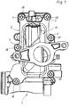
- Fig. 7 a view is shown on the overall arrangement, wherein the diffuser 16 is fixed by means of screws 18 on the housing 2. All other reference numerals are identical to those of the same parts Fig. 1 to 6 match.
- the shape of the pins 10 can be selected according to the application.
- the pins and the corresponding recesses have, at least in sections, an elliptical and / or circular and / or angular and / or oblong contour.
Landscapes
- Engineering & Computer Science (AREA)
- Mechanical Engineering (AREA)
- General Engineering & Computer Science (AREA)
- Physics & Mathematics (AREA)
- Thermal Sciences (AREA)
- Heat-Exchange Devices With Radiators And Conduit Assemblies (AREA)
- Chemical & Material Sciences (AREA)
- Combustion & Propulsion (AREA)
Description
- Die Erfindung betrifft einen Wärmetauscher, insbesondere Abgaskühler der im Oberbegriff des Anspruchs 1 angegebenen Gattung.
- In modernen Verbrennungsmotoren wird als Mittel zur Reduzierung der Stickstoff-Emissionen ein Teilstrom des Abgases abgezweigt und rückgeführt, um der Verbrennungsluft im Ansaugsystem des Verbrennungsmotors beigemischt zu werden. Um die Verbrennungstemperatur abzusenken und damit die Stickoxid-Produktion zu verringern, werden Abgaskühler eingesetzt, in denen das rückgeführte Abgas mittels Luft oder einem anderen Kühlfluid gekühlt wird. Es hat sich herausgestellt, dass durch die thermische Einwirkung beim Schweißen der auf der Flanschfläche des Gehäuses liegende Boden sich relativ zum Flansch bewegen kann und dadurch keine genaue Lage der Wärmetauscherrohre (Winglets) im Gehäuse gegeben ist und der Zugang von Schrauben zu am Gehäuse angeordneten Gewindebohrungen nicht sichergestellt ist. Solche als Winglets bezeichnete Wärmetauscherrohre sind beispielsweise aus der
DE 10 2010 043 309 A1 bekannt. - In der
DE 10 2009 050 884 A1 ist ein Abgaswärmetauscher, insbesondere für ein Kraftfahrzeug beschrieben, der mindestens einen Diffusor zum Zuführen und/oder Abführen eines Abgasstroms, einen Tauscherbereich und ein von einem Kühlmittel durchströmbares Gehäuse umfasst. Der Tauscherbereich wird aus einer Vielzahl von sich in axialer Richtung erstreckenden Tauscherrohren gebildet, die an einem Ende mit einem Boden fluiddicht verbunden sind. - Die
WO 2014/016192 A1 offenbart einen Abgaskühler mit einem Gehäuse, das eine Öffnung aufweist, in die ein aus Wärmetauscherrohren gebildeter Wärmetauscherblock eingesetzt ist. Dieser hat einen Boden, in dem die Enden der Wärmetauscherrohre fluiddicht aufgenommen sind. Am Gehäuse ist ein die Öffnung umgebender Flansch ausgebildet, auf dem der Boden zur Anlage gebracht ist. Im Bereich des Flansches sind Vorsprünge vorgesehen, die zum Ausrichten des Bodens an dessen Rand angreifen. - Aus der
DE 10 2009 000 263 A1 ist ein gegossener Wärmetauscher bekannt, bei dem keine Maßnahmen zur Ausrichtung des Bodens zum Flansch offenbart sind. - Der Erfindung liegt die Aufgabe zugrunde, einen Wärmetauscher der eingangs genannten Gattung zu schaffen, bei dem in einfacher Herstellung der Boden auf dem Flansch des Gehäuses auf einfache Weise exakt positioniert wird und eine Relativbewegung des Bodens auf der Flanschfläche mit Sicherheit verhindert wird.
- Diese Aufgabe wird durch einen Wärmetauscher mit den Merkmalen des Anspruchs 1 gelöst.
- Eine relative Verschiebung des Bodens auf dem Flansch beim bzw. nach dem Schweißen wird durch die vorgesehenen Pins verhindert und auf diese Weise die Lage der Wärmetauscherrohre relativ zum Gehäuse genau festgelegt. Außerdem wird der Zugang von Befestigungsschrauben zu Gewindebohrungen neben dem Flansch gesichert. Die exakte Positionierung erspart eine nachträgliche Dimensionskontrolle. Da die Pins gleichzeitig mit dem Gießen des Gehäuses hergestellt werden, sind keine zusätzlichen Bauteile und Arbeitsschritte zu deren Anbringung erforderlich. Dadurch und durch die Einsparung der nachträglichen Dimensionskontrolle ergibt sich ein erheblicher Kostenvorteil gegenüber der Herstellung bekannter Abgaskühler.
- Nach einer vorteilhaften Ausführungsform der Erfindung sind die Pins diametral gegenüberliegend zu der Öffnung vorgesehen. Dadurch ist der Boden am effektivsten gegen Verdrehung fixiert.
- Gemäß einer vorteilhaften Ausgestaltung der Erfindung ist vorgesehen, dass die Pins an ihrem Fuß von einer umlaufenden Nut umgeben sind. Dadurch wird eine Gratbildung und hohe Kerbwirkung am Übergang zwischen Pinansatz und Gehäusestirnfläche (Flanschfläche) vermieden. Während der Bearbeitung der Stirnfläche des Gehäuses auf das Maß der gewünschten Gehäuselänge werden die Pins vom Fräser umfahren. Der Pin wird beim Fräsen nicht berührt. Die umlaufende Nut weist bezüglich ihres Querschnitts vorzugsweise einen Radius von 0,5 mm bis 1,5 mm auf. Der Fräser bearbeitet die Stirnfläche im Abstand von ca. 0,5 mm entfernt zum Pin. Des Weiteren ist es vorteilhaft, dass die Pins und die entsprechenden Ausnehmungen zumindest abschnittsweise eine elliptische und/oder kreisförmige und/oder eckige und/oder längliche Kontur aufweisen. Somit lassen sich die Pins beispielsweise auch ganz am Rand des Flansches positionieren. Es ist außerdem vorteilhaft, dass die Pins eine Höhe aufweisen, die ausreichend ist, um bei an dem Flansch anliegendem Boden aus dem Boden hervorzustehen. Auf diese Weise kann ein auf dem Boden aufliegender Diffusor exakt positioniert werden, indem die Pins in entsprechende Öffnungen an der dem Boden zugewandten Seite des Diffusors greifen. Dadurch wird der Diffusor mittels der Pins relativ zum Gehäuse zentriert. Dadurch entfällt aufwendiges Vermessen der Schnittstellen am Ende der Produktionslinie, wodurch Investitionen in eine Einrichtung für die Dimensionskontrolle eingespart werden. Vorzugsweise weist der Boden eine der Form des Flanschs des Gehäuses angepasste Form auf. Dadurch wird eine großflächige gleichmäßige Anlage des Bodens am Flansch erreicht. Gemäß einer weiteren Ausgestaltung sind an einem äußeren Rand des Flansches Vorsprünge oder Arme mit darin angeordneten Gewindebohrungen vorgesehen, und am Rand des Bodens sind auf gleiche Weise gestaltete Vorsprünge und Arme mit darin angeordneten Bohrungen vorgesehen. Durch die auf gleiche Weise gestalteten Vorsprünge und Arme mit Bohrungen, in denen Befestigungsschrauben aufgenommen werden, wird der Diffusor befestigt und der Boden gegen den Flansch fest verspannt.
- Ein Ausführungsbeispiel der Erfindung ist nachstehend anhand der Zeichnung näher erläutert. In der Zeichnung zeigt:
- Fig. 1
- eine Ansicht eines Gehäuseflansches an einem Gehäuse eines Kühlers, insbesondere Abgaswärmetauschers,
- Fig. 2
- einen Boden zur Aufnahme der Enden von Wärmetauscherrohren (Winglets),
- Fig. 3
- Darstellung eines am Gehäuseflansch angeformten Arms mit einem aus der Flanschebene vorstehenden Pin,
- Fig. 4
- einen Ausschnitt des Gehäuseflanschs mit einem entsprechenden Abschnitt des Bodens,
- Fig. 5
- einen Ausschnitt des Gehäuseflansches mit angeformtem Arm und zugefügtem Boden,
- Fig. 6
- einen Ausschnitt des Gehäuseflanschs gemäß
Fig. 4 mit darüber dargestelltem Ausschnitt des Bodens und eines Diffusors, - Fig. 7
- eine Ansicht auf einen am Gehäuseflansch befestigten Diffusor.
- In
Fig. 1 ist eine Ansicht auf einen Flansch 1 eines Gehäuses 2 eines Wärmetauschers 3, beispielsweise eines Abgaskühlers gezeigt. Der Flansch 1 umgibt eine im Wesentlichen rechteckige Öffnung 4, die einen Schacht zur Aufnahme eines eine Vielzahl von Wärmetauscherrohren (Winglets) umfassenden Wärmetauscherblocks bildet. Seitlich am Flansch 1 sind Vorsprünge 6, 8 und Arme 7 angeformt, in denen Gewindebohrungen 9 zur Aufnahme von Befestigungsschrauben - was später noch erläutert wird - dienen. An dem Vorsprung 8 ist benachbart zu der Gewindebohrung 9 ein Pin 10 angeordnet, der senkrecht aus der Flanschfläche des Flansches 1 hervorsteht. Ein solcher Pin 10 ist außerdem an dem inFig. 1 linken Arm 7 vorgesehen. Durch diese Anordnung befinden sich die Pins 10 an bezogen auf die Flanschfläche diagonal gegenüberliegenden Stellen des Flansches 1. Die Pins 10 sind an dem Flansch 1 angegossen, d. h. sie werden beim Gießen des Gehäuses 2 erzeugt und brauchen nicht nachträglich angebaut werden. - Die
Fig. 2 zeigt einen Boden 11 mit einer Vielzahl von Öffnungen 12, in denen die Enden von Wärmetauscherrohren aufgenommen und stoffschlüssig verbunden, insbesondere geschweißt sind. Die Form des Bodens 11 entspricht der Form des Flansches 1 inFig. 1 einschließlich der Vorsprünge 6' und 8' sowie der Arme 7'. Durch diese Form des Bodens 11 ergibt sich eine Anlagefläche zur Anlage des Bodens 11 auf dem Flansch 1. In den Vorsprüngen 6', 8' und Armen 7' sind Bohrungen oder gestanzte Löcher 13, die deckungsgleich mit den Gewindebohrungen 9 am Flansch 1 (vgl.Fig. 1 ) sind. Außerdem sind Bohrungen 14 bzw. Öffnungen vorgesehen, die bezüglich ihrer Lage und Größe geeignet sind, die Pins 10 (vgl.Fig. 1 ) aufzunehmen, derart, dass die Pins 10 exakt in die Bohrungen 14 passen. - In
Fig. 3 ist einer der am Flansch 1 des Gehäuses 2 angeformten Arme 7 gezeigt, mit der im Arm 7 angeordneten Gewindebohrung 9 und dem Pin 10. Der Pin 10 weist an seinem Fuß eine umlaufende Nut 15 auf, die ebenfalls beim Gießen des Gehäuses 2 bereits erzeugt wird. Die umlaufende Nut hat bezüglich ihres Querschnitts vorzugsweise einen Radius von 0,5 mm. - Die
Fig. 4 zeigt, dass der Boden 11 dem Flansch 1 zugeführt wird, was allerdings erst der Fall ist, wenn der Boden 11 mit Wärmetauscherrohren 17 bestückt ist, wie dies inFig. 6 gezeigt ist. Beim Zuführen des Bodens 11 zum Flansch 1 werden beide inFig. 1 gezeigten Pins 10 in die jeweilige Öffnung 14 im Boden 11 eingeführt, wodurch eine exakte Positionierung des Bodens 11 auf dem Flansch 1 erfolgt. Durch die Pins 10 in den Öffnungen 14 wird auch eine spätere relative Bewegung des Bodens 11 zur Flanschfläche verhindert. - Aus
Fig. 5 ist ersichtlich, dass der Pin 10 bei auf den Flansch 1 aufgelegtem Boden 11 aus der Bodenebene hervorsteht und dass die Bohrung 13 mit der Gewindebohrung 9 deckungsgleich ist. Dadurch wird sichergestellt, dass die Befestigungsschrauben bei der Endmontage zuverlässig eingeführt werden können. - Die
Fig. 6 zeigt, dass die Wärmetauscherrohre 5 bzw. deren Enden im Boden 11 aufgenommen sind. Beim Zusammenbau des Wärmetauschers 3 wird der aus den Wärmetauscherrohren 5 gebildete Block in die inFig. 1 gezeigte Öffnung gesteckt, wobei der Boden 11 auf dem Flansch 1 zur Anlage kommt. Die genaue Positionierung des Bodens 11 auf dem Flansch 1 erfolgt durch das Einführen der insbesondere diametral angeordneten Pins 10 (vgl.Fig. 1 ) in die Bohrungen 14, denn die Dimensionierung von Pin 10 und Bohrung 14 ist so gewählt, dass ein relatives Gleiten des Bodens 11 auf der Flanschfläche ausgeschlossen ist. Durch die genaue Positionierung wird auch gewährleistet, dass die Bohrungen bzw. Löcher 13 deckungsgleich mit den Gewindebohrungen 9 sind und somit ein Abdecken der Gewindebohrungen 9 ausgeschlossen ist. AusFig. 6 ist weiter ersichtlich, dass nach Montage des Wärmetauscherblocks im Gehäuse 2 auf den Boden 11 ein Diffusor 16 aufgesetzt wird. Dieser Diffusor 16 weist an seiner dem Boden 11 zugewandten Fläche entsprechende Öffnungen auf, in die die über den Boden 11 herausstehenden Pins 10 eingeführt werden, so dass auch der Diffusor 16 eine exakt definierte Position einnimmt. Der Diffusor 16 hat eine an die Form des Bodens 11 angepasste Form einer Anlagefläche, an deren äußerem Rand ebenfalls Vorsprünge 6 und Arme 7 ausgebildet sind, wie dies am Flansch 1 und Boden 11 der Fall ist. Die Vorsprünge 6 und Arme 7 des Diffusors 16 sind ebenfalls mit Bohrungen 17 versehen, die deckungsgleich mit den Bohrungen 13 am Boden 11 und den Gewindebohrungen 9 sind, so dass Schrauben zur Befestigung des Diffusors 16 und dem festen Verspannen der Bauelemente 16, 11 und 2 eingeführt und festgeschraubt werden können. - In
Fig. 7 ist eine Ansicht auf die Gesamtanordnung gezeigt, wobei der Diffusor 16 mittels Schrauben 18 auf dem Gehäuse 2 befestigt ist. Alle übrigen Bezugszeichen stimmen für gleiche Teile mit denjenigen derFig. 1 bis 6 überein. - Die Form der Pins 10 kann dem Anwendungsfall entsprechend gewählt werden. Vorteihaft weisen die Pins und die entsprechenden Ausnehmungen zumindest abschnittsweise eine elliptische und/oder kreisförmige und/oder eckige und/oder längliche Kontur auf.
Claims (9)
- Wärmetauscher (3), insbesondere Abgaskühler mit einem Gehäuse (2), das eine Öffnung (4) aufweist, in die ein aus Wärmetauscherrohren (5) gebildeter Wärmetauscherblock eingesetzt ist, und mit einem Boden (11), in dem Enden der Wärmetauscherrohre (5) fluiddicht aufgenommen sind, wobei am Gehäuse (2) ein die Öffnung (4) umgebender Flansch (1) ausgebildet ist, auf dem der Boden (11) zur Anlage gebracht ist, wobei im Bereich des Flansches (1) mindestens zwei aus einer Flanschebene hervorstehende Pins (10) vorgesehen sind und der Boden mindestens zwei Ausnehmungen (14) aufweist, in die die Pins (10) eingeführt sind, wobei die Pins (10) einstückig mit dem Gehäuse (2) ausgeführt sind,
dadurch gekennzeichnet, dass die Pins (10) bei der Herstellung des Gehäuses (2) angegossen sind. - Wärmetauscher nach Anspruch 1,
dadurch gekennzeichnet, dass die Pins diametral gegenüberliegend zu der Öffnung (4) vorgesehen sind. - Wärmetauscher nach Anspruch 1 oder 2,
dadurch gekennzeichnet, dass die Pins (10) an ihrem Fuß von einer umlaufenden Nut (15) umgeben sind. - Wärmetauscher nach Anspruch 3,
dadurch gekennzeichnet, dass die umlaufende Nut (15) einen Radius von 0,5 mm bis 1,5 mm aufweist. - Wärmetauscher nach einem der vorhergehenden Ansprüche,
dadurch gekennzeichnet, dass die Pins und die entsprechenden Ausnehmungen zumindest abschnittsweise eine elliptische und/oder kreisförmige und/oder eckige und/oder längliche Kontur aufweisen. - Wärmetauscher nach einem der vorhergehenden Ansprüche,
dadurch gekennzeichnet, dass die Pins (10) eine Höhe aufweisen, die ausreichend ist, um bei an dem Flansch (1) anliegendem Boden (11) aus dem Boden (11) hervorzustehen. - Wärmetauscher nach einem der vorhergehenden Ansprüche,
dadurch gekennzeichnet, dass der Boden (11) eine der Form des Flansches (1) des Gehäuses (2) angepasste Form aufweist. - Wärmetauscher einem der vorhergehenden Ansprüche,
dadurch gekennzeichnet, dass an einem äußeren Rand des Flanschs (1) Vorsprünge (6, 8) oder Arme (7) mit darin angeordneten Gewindebohrungen (9) vorgesehen sind und am Rand des Bodens (11) auf gleiche Weise gestaltete Vorsprünge (6', 8') und Arme (7') mit darin angeordneten Bohrungen oder gestanzten Löchern (13) vorgesehen sind. - Wärmetauscher nach Anspruch 8,
dadurch gekennzeichnet, dass der Boden (11) mittels in die Gewindebohrung (9) gedrehten Schrauben (18) gegen den Flansch (1) gespannt ist.
Applications Claiming Priority (2)
| Application Number | Priority Date | Filing Date | Title |
|---|---|---|---|
| DE102014008465.5A DE102014008465A1 (de) | 2014-06-06 | 2014-06-06 | Wärmetauscher, insbesondere Abgaskühler |
| PCT/EP2015/001130 WO2015185214A1 (de) | 2014-06-06 | 2015-06-03 | Wärmetauscher, insbesondere abgaskühler |
Publications (2)
| Publication Number | Publication Date |
|---|---|
| EP3152508A1 EP3152508A1 (de) | 2017-04-12 |
| EP3152508B1 true EP3152508B1 (de) | 2018-08-15 |
Family
ID=53398028
Family Applications (1)
| Application Number | Title | Priority Date | Filing Date |
|---|---|---|---|
| EP15729075.0A Active EP3152508B1 (de) | 2014-06-06 | 2015-06-03 | Wärmetauscher, insbesondere abgaskühler |
Country Status (4)
| Country | Link |
|---|---|
| EP (1) | EP3152508B1 (de) |
| KR (1) | KR20170020843A (de) |
| DE (1) | DE102014008465A1 (de) |
| WO (1) | WO2015185214A1 (de) |
Families Citing this family (6)
| Publication number | Priority date | Publication date | Assignee | Title |
|---|---|---|---|---|
| US20170114225A1 (en) | 2015-10-27 | 2017-04-27 | Schott Gemtron Corp. | Coating compositions for glass substrates |
| US10591652B2 (en) | 2015-11-20 | 2020-03-17 | Schott Gemtron Corp. | Multi-layer coated glass substrate |
| EP3493683A4 (de) | 2016-08-03 | 2019-08-14 | Schott Gemtron Corporation | Ofen mit einem dielektrisch beschichteten glassubstrat zur absorption von elektromagnetischer strahlung und emission von wärmestrahlung |
| DE102017210400A1 (de) * | 2017-06-21 | 2018-12-27 | Mahle International Gmbh | Wärmeübertrager |
| ES2724915A1 (es) * | 2018-03-16 | 2019-09-17 | Valeo Termico Sa | Intercambiador de calor para gases y procedimiento de montaje de un intercambiador de calor |
| KR102516395B1 (ko) * | 2021-07-23 | 2023-03-30 | 백승욱 | 세라믹 제품의 수율을 향상시키기 위한 프레스 장치 및 이를 이용한 세라믹 제조 방법 |
Family Cites Families (8)
| Publication number | Priority date | Publication date | Assignee | Title |
|---|---|---|---|---|
| US3254709A (en) * | 1963-07-30 | 1966-06-07 | Richard G Lyall | Heat exchanger |
| DE102006051000A1 (de) * | 2005-10-26 | 2007-07-12 | Behr Gmbh & Co. Kg | Wärmetauscher, Verfahren zur Herstellung eines Wärmetauschers |
| DE202009018892U1 (de) * | 2009-01-15 | 2014-04-17 | Halla Visteon Climate Control Corporation | Wärmetauscher für den Abgasstrang eines Kraftfahrzeugs mit verbessertem Temperaturausgleich im Kühlmittel |
| DE102009050884A1 (de) | 2009-10-27 | 2011-04-28 | Behr Gmbh & Co. Kg | Abgaswärmetauscher |
| DE102010043309A1 (de) | 2010-11-03 | 2012-05-03 | Behr Gmbh & Co. Kg | Verfahren zum Anbringen von Winglets an einem Grundmaterial und Wingletrohr |
| EP2463490B1 (de) * | 2010-12-10 | 2015-09-09 | Perkins Engines Company Limited | Verbesserungen an oder in Zusammenhang mit Gaskühlern für Verbrennungsmotoren |
| DE102011077141A1 (de) * | 2011-06-07 | 2012-12-13 | Behr Gmbh & Co. Kg | Wärmetauscher |
| FR2993969B1 (fr) * | 2012-07-24 | 2018-07-27 | Valeo Systemes Thermiques | Echangeur de chaleur pour vehicule automobile comportant une bride de fixation |
-
2014
- 2014-06-06 DE DE102014008465.5A patent/DE102014008465A1/de not_active Withdrawn
-
2015
- 2015-06-03 WO PCT/EP2015/001130 patent/WO2015185214A1/de not_active Ceased
- 2015-06-03 KR KR1020177000472A patent/KR20170020843A/ko not_active Ceased
- 2015-06-03 EP EP15729075.0A patent/EP3152508B1/de active Active
Non-Patent Citations (1)
| Title |
|---|
| None * |
Also Published As
| Publication number | Publication date |
|---|---|
| DE102014008465A1 (de) | 2015-12-17 |
| WO2015185214A1 (de) | 2015-12-10 |
| KR20170020843A (ko) | 2017-02-24 |
| EP3152508A1 (de) | 2017-04-12 |
Similar Documents
| Publication | Publication Date | Title |
|---|---|---|
| WO2015185214A1 (de) | Wärmetauscher, insbesondere abgaskühler | |
| EP1991838B1 (de) | Anordnung eines luftmassenmessers an einem strömungskanal | |
| DE102012011848A1 (de) | Befestigungsanordnung | |
| WO2014124847A1 (de) | Kühleinrichtung für ein kraftfahrzeug | |
| EP1452816B1 (de) | Plattenwärmetauscher | |
| DE102007063255A1 (de) | Lagereinrichtung | |
| DE69607663T2 (de) | Baugruppe mit Gebläse und Wärmetauscher | |
| DE102008015154A1 (de) | Führungs- oder Spannschiene in einem Zugmitteltrieb | |
| DE69701325T2 (de) | Anordnung von radiator und kondensator | |
| EP4584106A1 (de) | Thermalmodulvorrichtung und fahrzeug mit der thermalmodulvorrichtung | |
| DE102011114786A1 (de) | Motorbaugruppe umfassend einen Lagerbock sowie Verfahren zu deren Montage | |
| DE69509734T2 (de) | Behälter für einen Wärmeaustauscher | |
| DE102018217241A1 (de) | Vorrichtung und elektronische Drosselklappensteueranordnung | |
| DE102008021268A1 (de) | Montagehilfe | |
| DE102019214119A1 (de) | Kühlsystem, Kraftfahrzeug | |
| DE102014222368A1 (de) | Thermostatventil | |
| EP2998684B1 (de) | Vorrichtung zur zuführung eines kühlmittels zu einem wärmeübertrager, vorzugsweise für einen abgaskühler eines verbrennungsmotors eines kraftfahrzeuges | |
| DE102021103945A1 (de) | Klappeneinheit für eine Klappenanlage, Klappenanlage für eine Verbrennungskraftmaschine, Verbrennungskraftmaschine für ein Kraftfahrzeug sowie Kraftfahrzeug | |
| DE102014213540A1 (de) | Hitzeschild | |
| EP2532855B1 (de) | Wärmetauscher | |
| DE112015001284B4 (de) | Anbringungsstruktur für ein Kraftmaschinenzubehör | |
| EP1801369B1 (de) | Saugrohr-Zylinderkopfanordnung | |
| DE102022134491B4 (de) | Klimatisierungssystem für ein Fahrzeug | |
| DE102013214403B4 (de) | Grundplatte für einen Fahrzeugwärmetauscher, Verfahren zu ihrer Herstellung, Wärmetauscher und Ölfiltermodul | |
| WO2006131220A1 (de) | Schweissverbund |
Legal Events
| Date | Code | Title | Description |
|---|---|---|---|
| STAA | Information on the status of an ep patent application or granted ep patent |
Free format text: STATUS: THE INTERNATIONAL PUBLICATION HAS BEEN MADE |
|
| PUAI | Public reference made under article 153(3) epc to a published international application that has entered the european phase |
Free format text: ORIGINAL CODE: 0009012 |
|
| STAA | Information on the status of an ep patent application or granted ep patent |
Free format text: STATUS: REQUEST FOR EXAMINATION WAS MADE |
|
| 17P | Request for examination filed |
Effective date: 20161202 |
|
| AK | Designated contracting states |
Kind code of ref document: A1 Designated state(s): AL AT BE BG CH CY CZ DE DK EE ES FI FR GB GR HR HU IE IS IT LI LT LU LV MC MK MT NL NO PL PT RO RS SE SI SK SM TR |
|
| AX | Request for extension of the european patent |
Extension state: BA ME |
|
| RIN1 | Information on inventor provided before grant (corrected) |
Inventor name: DREIZLER, SABINE Inventor name: DERLETH, MARTIN Inventor name: PANIC, PREDRAG |
|
| DAV | Request for validation of the european patent (deleted) | ||
| DAX | Request for extension of the european patent (deleted) | ||
| GRAP | Despatch of communication of intention to grant a patent |
Free format text: ORIGINAL CODE: EPIDOSNIGR1 |
|
| STAA | Information on the status of an ep patent application or granted ep patent |
Free format text: STATUS: GRANT OF PATENT IS INTENDED |
|
| INTG | Intention to grant announced |
Effective date: 20171115 |
|
| GRAJ | Information related to disapproval of communication of intention to grant by the applicant or resumption of examination proceedings by the epo deleted |
Free format text: ORIGINAL CODE: EPIDOSDIGR1 |
|
| STAA | Information on the status of an ep patent application or granted ep patent |
Free format text: STATUS: REQUEST FOR EXAMINATION WAS MADE |
|
| GRAP | Despatch of communication of intention to grant a patent |
Free format text: ORIGINAL CODE: EPIDOSNIGR1 |
|
| STAA | Information on the status of an ep patent application or granted ep patent |
Free format text: STATUS: GRANT OF PATENT IS INTENDED |
|
| INTC | Intention to grant announced (deleted) | ||
| INTG | Intention to grant announced |
Effective date: 20180209 |
|
| GRAS | Grant fee paid |
Free format text: ORIGINAL CODE: EPIDOSNIGR3 |
|
| GRAA | (expected) grant |
Free format text: ORIGINAL CODE: 0009210 |
|
| STAA | Information on the status of an ep patent application or granted ep patent |
Free format text: STATUS: THE PATENT HAS BEEN GRANTED |
|
| AK | Designated contracting states |
Kind code of ref document: B1 Designated state(s): AL AT BE BG CH CY CZ DE DK EE ES FI FR GB GR HR HU IE IS IT LI LT LU LV MC MK MT NL NO PL PT RO RS SE SI SK SM TR |
|
| REG | Reference to a national code |
Ref country code: CH Ref legal event code: EP Ref country code: GB Ref legal event code: FG4D Free format text: NOT ENGLISH Ref country code: AT Ref legal event code: REF Ref document number: 1030277 Country of ref document: AT Kind code of ref document: T Effective date: 20180815 |
|
| REG | Reference to a national code |
Ref country code: IE Ref legal event code: FG4D Free format text: LANGUAGE OF EP DOCUMENT: GERMAN |
|
| REG | Reference to a national code |
Ref country code: DE Ref legal event code: R096 Ref document number: 502015005446 Country of ref document: DE |
|
| REG | Reference to a national code |
Ref country code: NL Ref legal event code: MP Effective date: 20180815 |
|
| REG | Reference to a national code |
Ref country code: LT Ref legal event code: MG4D |
|
| PG25 | Lapsed in a contracting state [announced via postgrant information from national office to epo] |
Ref country code: NL Free format text: LAPSE BECAUSE OF FAILURE TO SUBMIT A TRANSLATION OF THE DESCRIPTION OR TO PAY THE FEE WITHIN THE PRESCRIBED TIME-LIMIT Effective date: 20180815 Ref country code: BG Free format text: LAPSE BECAUSE OF FAILURE TO SUBMIT A TRANSLATION OF THE DESCRIPTION OR TO PAY THE FEE WITHIN THE PRESCRIBED TIME-LIMIT Effective date: 20181115 Ref country code: LT Free format text: LAPSE BECAUSE OF FAILURE TO SUBMIT A TRANSLATION OF THE DESCRIPTION OR TO PAY THE FEE WITHIN THE PRESCRIBED TIME-LIMIT Effective date: 20180815 Ref country code: IS Free format text: LAPSE BECAUSE OF FAILURE TO SUBMIT A TRANSLATION OF THE DESCRIPTION OR TO PAY THE FEE WITHIN THE PRESCRIBED TIME-LIMIT Effective date: 20181215 Ref country code: SE Free format text: LAPSE BECAUSE OF FAILURE TO SUBMIT A TRANSLATION OF THE DESCRIPTION OR TO PAY THE FEE WITHIN THE PRESCRIBED TIME-LIMIT Effective date: 20180815 Ref country code: NO Free format text: LAPSE BECAUSE OF FAILURE TO SUBMIT A TRANSLATION OF THE DESCRIPTION OR TO PAY THE FEE WITHIN THE PRESCRIBED TIME-LIMIT Effective date: 20181115 Ref country code: GR Free format text: LAPSE BECAUSE OF FAILURE TO SUBMIT A TRANSLATION OF THE DESCRIPTION OR TO PAY THE FEE WITHIN THE PRESCRIBED TIME-LIMIT Effective date: 20181116 Ref country code: FI Free format text: LAPSE BECAUSE OF FAILURE TO SUBMIT A TRANSLATION OF THE DESCRIPTION OR TO PAY THE FEE WITHIN THE PRESCRIBED TIME-LIMIT Effective date: 20180815 Ref country code: RS Free format text: LAPSE BECAUSE OF FAILURE TO SUBMIT A TRANSLATION OF THE DESCRIPTION OR TO PAY THE FEE WITHIN THE PRESCRIBED TIME-LIMIT Effective date: 20180815 |
|
| PG25 | Lapsed in a contracting state [announced via postgrant information from national office to epo] |
Ref country code: AL Free format text: LAPSE BECAUSE OF FAILURE TO SUBMIT A TRANSLATION OF THE DESCRIPTION OR TO PAY THE FEE WITHIN THE PRESCRIBED TIME-LIMIT Effective date: 20180815 Ref country code: HR Free format text: LAPSE BECAUSE OF FAILURE TO SUBMIT A TRANSLATION OF THE DESCRIPTION OR TO PAY THE FEE WITHIN THE PRESCRIBED TIME-LIMIT Effective date: 20180815 Ref country code: LV Free format text: LAPSE BECAUSE OF FAILURE TO SUBMIT A TRANSLATION OF THE DESCRIPTION OR TO PAY THE FEE WITHIN THE PRESCRIBED TIME-LIMIT Effective date: 20180815 |
|
| PG25 | Lapsed in a contracting state [announced via postgrant information from national office to epo] |
Ref country code: PL Free format text: LAPSE BECAUSE OF FAILURE TO SUBMIT A TRANSLATION OF THE DESCRIPTION OR TO PAY THE FEE WITHIN THE PRESCRIBED TIME-LIMIT Effective date: 20180815 Ref country code: EE Free format text: LAPSE BECAUSE OF FAILURE TO SUBMIT A TRANSLATION OF THE DESCRIPTION OR TO PAY THE FEE WITHIN THE PRESCRIBED TIME-LIMIT Effective date: 20180815 Ref country code: IT Free format text: LAPSE BECAUSE OF FAILURE TO SUBMIT A TRANSLATION OF THE DESCRIPTION OR TO PAY THE FEE WITHIN THE PRESCRIBED TIME-LIMIT Effective date: 20180815 Ref country code: CZ Free format text: LAPSE BECAUSE OF FAILURE TO SUBMIT A TRANSLATION OF THE DESCRIPTION OR TO PAY THE FEE WITHIN THE PRESCRIBED TIME-LIMIT Effective date: 20180815 Ref country code: RO Free format text: LAPSE BECAUSE OF FAILURE TO SUBMIT A TRANSLATION OF THE DESCRIPTION OR TO PAY THE FEE WITHIN THE PRESCRIBED TIME-LIMIT Effective date: 20180815 Ref country code: ES Free format text: LAPSE BECAUSE OF FAILURE TO SUBMIT A TRANSLATION OF THE DESCRIPTION OR TO PAY THE FEE WITHIN THE PRESCRIBED TIME-LIMIT Effective date: 20180815 |
|
| REG | Reference to a national code |
Ref country code: DE Ref legal event code: R097 Ref document number: 502015005446 Country of ref document: DE |
|
| PG25 | Lapsed in a contracting state [announced via postgrant information from national office to epo] |
Ref country code: SK Free format text: LAPSE BECAUSE OF FAILURE TO SUBMIT A TRANSLATION OF THE DESCRIPTION OR TO PAY THE FEE WITHIN THE PRESCRIBED TIME-LIMIT Effective date: 20180815 Ref country code: SM Free format text: LAPSE BECAUSE OF FAILURE TO SUBMIT A TRANSLATION OF THE DESCRIPTION OR TO PAY THE FEE WITHIN THE PRESCRIBED TIME-LIMIT Effective date: 20180815 Ref country code: DK Free format text: LAPSE BECAUSE OF FAILURE TO SUBMIT A TRANSLATION OF THE DESCRIPTION OR TO PAY THE FEE WITHIN THE PRESCRIBED TIME-LIMIT Effective date: 20180815 |
|
| PLBE | No opposition filed within time limit |
Free format text: ORIGINAL CODE: 0009261 |
|
| STAA | Information on the status of an ep patent application or granted ep patent |
Free format text: STATUS: NO OPPOSITION FILED WITHIN TIME LIMIT |
|
| 26N | No opposition filed |
Effective date: 20190516 |
|
| PG25 | Lapsed in a contracting state [announced via postgrant information from national office to epo] |
Ref country code: SI Free format text: LAPSE BECAUSE OF FAILURE TO SUBMIT A TRANSLATION OF THE DESCRIPTION OR TO PAY THE FEE WITHIN THE PRESCRIBED TIME-LIMIT Effective date: 20180815 |
|
| PG25 | Lapsed in a contracting state [announced via postgrant information from national office to epo] |
Ref country code: MC Free format text: LAPSE BECAUSE OF FAILURE TO SUBMIT A TRANSLATION OF THE DESCRIPTION OR TO PAY THE FEE WITHIN THE PRESCRIBED TIME-LIMIT Effective date: 20180815 |
|
| REG | Reference to a national code |
Ref country code: CH Ref legal event code: PL |
|
| GBPC | Gb: european patent ceased through non-payment of renewal fee |
Effective date: 20190603 |
|
| REG | Reference to a national code |
Ref country code: BE Ref legal event code: MM Effective date: 20190630 |
|
| PG25 | Lapsed in a contracting state [announced via postgrant information from national office to epo] |
Ref country code: TR Free format text: LAPSE BECAUSE OF FAILURE TO SUBMIT A TRANSLATION OF THE DESCRIPTION OR TO PAY THE FEE WITHIN THE PRESCRIBED TIME-LIMIT Effective date: 20180815 |
|
| PG25 | Lapsed in a contracting state [announced via postgrant information from national office to epo] |
Ref country code: GB Free format text: LAPSE BECAUSE OF NON-PAYMENT OF DUE FEES Effective date: 20190603 Ref country code: IE Free format text: LAPSE BECAUSE OF NON-PAYMENT OF DUE FEES Effective date: 20190603 |
|
| PG25 | Lapsed in a contracting state [announced via postgrant information from national office to epo] |
Ref country code: BE Free format text: LAPSE BECAUSE OF NON-PAYMENT OF DUE FEES Effective date: 20190630 Ref country code: LI Free format text: LAPSE BECAUSE OF NON-PAYMENT OF DUE FEES Effective date: 20190630 Ref country code: LU Free format text: LAPSE BECAUSE OF NON-PAYMENT OF DUE FEES Effective date: 20190603 Ref country code: CH Free format text: LAPSE BECAUSE OF NON-PAYMENT OF DUE FEES Effective date: 20190630 |
|
| PG25 | Lapsed in a contracting state [announced via postgrant information from national office to epo] |
Ref country code: PT Free format text: LAPSE BECAUSE OF FAILURE TO SUBMIT A TRANSLATION OF THE DESCRIPTION OR TO PAY THE FEE WITHIN THE PRESCRIBED TIME-LIMIT Effective date: 20181215 Ref country code: FR Free format text: LAPSE BECAUSE OF NON-PAYMENT OF DUE FEES Effective date: 20190630 |
|
| PG25 | Lapsed in a contracting state [announced via postgrant information from national office to epo] |
Ref country code: CY Free format text: LAPSE BECAUSE OF FAILURE TO SUBMIT A TRANSLATION OF THE DESCRIPTION OR TO PAY THE FEE WITHIN THE PRESCRIBED TIME-LIMIT Effective date: 20180815 |
|
| PG25 | Lapsed in a contracting state [announced via postgrant information from national office to epo] |
Ref country code: HU Free format text: LAPSE BECAUSE OF FAILURE TO SUBMIT A TRANSLATION OF THE DESCRIPTION OR TO PAY THE FEE WITHIN THE PRESCRIBED TIME-LIMIT; INVALID AB INITIO Effective date: 20150603 Ref country code: MT Free format text: LAPSE BECAUSE OF FAILURE TO SUBMIT A TRANSLATION OF THE DESCRIPTION OR TO PAY THE FEE WITHIN THE PRESCRIBED TIME-LIMIT Effective date: 20180815 |
|
| REG | Reference to a national code |
Ref country code: AT Ref legal event code: MM01 Ref document number: 1030277 Country of ref document: AT Kind code of ref document: T Effective date: 20200603 |
|
| PG25 | Lapsed in a contracting state [announced via postgrant information from national office to epo] |
Ref country code: AT Free format text: LAPSE BECAUSE OF NON-PAYMENT OF DUE FEES Effective date: 20200603 |
|
| PG25 | Lapsed in a contracting state [announced via postgrant information from national office to epo] |
Ref country code: MK Free format text: LAPSE BECAUSE OF FAILURE TO SUBMIT A TRANSLATION OF THE DESCRIPTION OR TO PAY THE FEE WITHIN THE PRESCRIBED TIME-LIMIT Effective date: 20180815 |
|
| P01 | Opt-out of the competence of the unified patent court (upc) registered |
Effective date: 20240527 |
|
| PGFP | Annual fee paid to national office [announced via postgrant information from national office to epo] |
Ref country code: DE Payment date: 20250618 Year of fee payment: 11 |