EP3152413B1 - Trägermodul - Google Patents
Trägermodul Download PDFInfo
- Publication number
- EP3152413B1 EP3152413B1 EP15719603.1A EP15719603A EP3152413B1 EP 3152413 B1 EP3152413 B1 EP 3152413B1 EP 15719603 A EP15719603 A EP 15719603A EP 3152413 B1 EP3152413 B1 EP 3152413B1
- Authority
- EP
- European Patent Office
- Prior art keywords
- carrier module
- base plate
- module according
- carrying
- carrying walls
- Prior art date
- Legal status (The legal status is an assumption and is not a legal conclusion. Google has not performed a legal analysis and makes no representation as to the accuracy of the status listed.)
- Not-in-force
Links
- 238000002485 combustion reaction Methods 0.000 claims description 5
- 229910000831 Steel Inorganic materials 0.000 claims description 4
- 238000005516 engineering process Methods 0.000 claims description 4
- 239000010959 steel Substances 0.000 claims description 4
- 238000005452 bending Methods 0.000 claims description 3
- 238000010276 construction Methods 0.000 claims 1
- 210000002414 leg Anatomy 0.000 description 7
- 229910052782 aluminium Inorganic materials 0.000 description 2
- XAGFODPZIPBFFR-UHFFFAOYSA-N aluminium Chemical compound [Al] XAGFODPZIPBFFR-UHFFFAOYSA-N 0.000 description 2
- 239000003562 lightweight material Substances 0.000 description 2
- 238000004519 manufacturing process Methods 0.000 description 2
- 239000004033 plastic Substances 0.000 description 2
- 229920003023 plastic Polymers 0.000 description 2
- RTAQQCXQSZGOHL-UHFFFAOYSA-N Titanium Chemical compound [Ti] RTAQQCXQSZGOHL-UHFFFAOYSA-N 0.000 description 1
- 230000015572 biosynthetic process Effects 0.000 description 1
- 238000006073 displacement reaction Methods 0.000 description 1
- 238000005553 drilling Methods 0.000 description 1
- 239000000835 fiber Substances 0.000 description 1
- 210000000245 forearm Anatomy 0.000 description 1
- 210000001061 forehead Anatomy 0.000 description 1
- 238000009434 installation Methods 0.000 description 1
- 239000000314 lubricant Substances 0.000 description 1
- 238000003754 machining Methods 0.000 description 1
- 239000000463 material Substances 0.000 description 1
- 229910052751 metal Inorganic materials 0.000 description 1
- 239000002184 metal Substances 0.000 description 1
- 210000000689 upper leg Anatomy 0.000 description 1
Images

Classifications
-
- F—MECHANICAL ENGINEERING; LIGHTING; HEATING; WEAPONS; BLASTING
- F01—MACHINES OR ENGINES IN GENERAL; ENGINE PLANTS IN GENERAL; STEAM ENGINES
- F01L—CYCLICALLY OPERATING VALVES FOR MACHINES OR ENGINES
- F01L1/00—Valve-gear or valve arrangements, e.g. lift-valve gear
- F01L1/02—Valve drive
- F01L1/04—Valve drive by means of cams, camshafts, cam discs, eccentrics or the like
- F01L1/047—Camshafts
- F01L1/053—Camshafts overhead type
-
- F—MECHANICAL ENGINEERING; LIGHTING; HEATING; WEAPONS; BLASTING
- F01—MACHINES OR ENGINES IN GENERAL; ENGINE PLANTS IN GENERAL; STEAM ENGINES
- F01L—CYCLICALLY OPERATING VALVES FOR MACHINES OR ENGINES
- F01L1/00—Valve-gear or valve arrangements, e.g. lift-valve gear
- F01L1/12—Transmitting gear between valve drive and valve
- F01L1/18—Rocking arms or levers
- F01L1/181—Centre pivot rocking arms
- F01L1/182—Centre pivot rocking arms the rocking arm being pivoted about an individual fulcrum, i.e. not about a common shaft
-
- F—MECHANICAL ENGINEERING; LIGHTING; HEATING; WEAPONS; BLASTING
- F01—MACHINES OR ENGINES IN GENERAL; ENGINE PLANTS IN GENERAL; STEAM ENGINES
- F01L—CYCLICALLY OPERATING VALVES FOR MACHINES OR ENGINES
- F01L1/00—Valve-gear or valve arrangements, e.g. lift-valve gear
- F01L1/20—Adjusting or compensating clearance
-
- F—MECHANICAL ENGINEERING; LIGHTING; HEATING; WEAPONS; BLASTING
- F01—MACHINES OR ENGINES IN GENERAL; ENGINE PLANTS IN GENERAL; STEAM ENGINES
- F01L—CYCLICALLY OPERATING VALVES FOR MACHINES OR ENGINES
- F01L1/00—Valve-gear or valve arrangements, e.g. lift-valve gear
- F01L1/02—Valve drive
- F01L1/04—Valve drive by means of cams, camshafts, cam discs, eccentrics or the like
- F01L1/047—Camshafts
- F01L2001/0476—Camshaft bearings
-
- F—MECHANICAL ENGINEERING; LIGHTING; HEATING; WEAPONS; BLASTING
- F01—MACHINES OR ENGINES IN GENERAL; ENGINE PLANTS IN GENERAL; STEAM ENGINES
- F01L—CYCLICALLY OPERATING VALVES FOR MACHINES OR ENGINES
- F01L1/00—Valve-gear or valve arrangements, e.g. lift-valve gear
- F01L1/02—Valve drive
- F01L1/04—Valve drive by means of cams, camshafts, cam discs, eccentrics or the like
- F01L1/047—Camshafts
- F01L1/053—Camshafts overhead type
- F01L2001/0535—Single overhead camshafts [SOHC]
-
- F—MECHANICAL ENGINEERING; LIGHTING; HEATING; WEAPONS; BLASTING
- F01—MACHINES OR ENGINES IN GENERAL; ENGINE PLANTS IN GENERAL; STEAM ENGINES
- F01L—CYCLICALLY OPERATING VALVES FOR MACHINES OR ENGINES
- F01L2303/00—Manufacturing of components used in valve arrangements
Definitions
- the invention relates to a support module for an OHC valve train of an internal combustion engine, with two upright and separate support walls, which at least indirectly with their upper forehead at least indirectly with a cylinder head cover and their Unterstirnen be connected to a cylinder head and at least one main and secondary bore for storage a cam and valve operating lever shaft therebetween.
- Such carrier modules are, for example, in 1-cylinder motorcycle engines with 2V technology in use and made of cast aluminum (see valve engine Hyundai engine KRM / KVS, installed in Hyundai CG 150 Titan (Brazil)).
- the levers for actuating the two gas exchange valves sit on separate shafts.
- Such a carrier module builds comparatively massive and takes up unnecessary space.
- the functional surfaces of the carrier module such as, for example, the holes for cam and valve actuation shaft (s) are subsequently machined by machining.
- the production costs and the costs are increased, which is particularly relevant in mass production.
- this object is achieved in that protrudes from the lower end of each support wall an orthogonally bent legs, which is mounted on a separate, an immediate connection of the support module with the cylinder head base plate, the base plate and the support walls with their legs punching-bending technology Steel sheet are shown.
- a lightweight and compact carrier module is particularly, but not exclusively, available for motorcycles, boats, or minisite engines.
- a module should be used in 1-cylinder engines.
- steel sheet board / tape
- other lightweight materials such as aluminum sheet, also packaged or otherwise reinforced, plastics, fiber or particle-reinforced, etc. to offer.
- the carrier module according to the invention is designed to receive only a central, short-throwing camshaft and at least one flanking valve operating lever shaft, wherein preferably an inlet and a Auslisterventilbetus Trentshebelwelle are provided and also more than one camshaft can be used.
- the protection of this invention also extends to cam and valve actuation lever shaft (s) and levers mounted thereon.
- a noteworthy advantage of the invention is the possibility of a kit formation. Over a combination of comparatively few groups of differently dimensioned supporting walls with comparatively few groups of differently dimensioned base plates, a large number of different carrier modules can be presented. It is conceivable, for example, also the combination of a standard base plate with different sized or differently spaced support walls or a combination of standard support walls with different sized base plates, etc.
- the legs of the supporting walls on the base plate are projecting from each other. Depending on the available installation space, these can also face each other or be rectified. Possibly.
- Each support wall or one of them can also consist of two contiguous sheet metal plates, so that a T-shapeditz effect on the base plate is conceivable and possible.
- Simple attachment forms of the support walls on the legs on the base plate are the subject of another subclaim. Accordingly, these may, for example, in the edge region of the feet welded to the base plate / soldered or glued. Alternatively, it is intended to rivets, screws or pegs, in which case the legs or the base plate can have a large number of holes, of which only a minority with the rivet, screw or pin connection are provided (modular principle, see.).
- the base plate has openings in the region of its edges, which can be, for example, punched holes, which openings serve to engage, for example, screws or centering pins for fastening the carrier module to the cylinder head.
- the proposed ⁇ lsiererschreibchen may consist of plastic or other lightweight material and with the respective support wall, for example. Snapped or clipped and be provided with a check valve.
- the support module 1 has two upright and mutually spaced support walls 2, which stand on their lower end brackets 4 orthogonally bent legs 10 on a separate base plate 11. As can be seen, the legs 10 protrude away from each other. They are fixed to the base plate 11 via seated in holes 13 rivet 12. In this case, only a subset of the prefabricated holes with rivets 12 are occupied, so that without a change in the base plate 11 and the support walls 2, only by lateral displacement last mentioned on the base plate 11, the support module 1 can be installed in different types of internal combustion engines.
- Each support wall 2 has an approximately central main bore 5.
- a camshaft 7 is rotatably mounted in the main bores 5.
- a window 18 is provided in the base plate 11.
- Each support wall 2 has two side bores 6. The latter are located on lug-like edge portions 16 of the support wall 2, in the upper- to the side face 3, 17.
- a valve operating lever shaft 8, 9 is mounted, wherein the valve operating lever shaft 8 acts as an inlet shaft and an intake rocker arm 20, and wherein the valve operating lever shaft 9 serves as an exhaust shaft and has an exhaust rocker arm 21.
- FIG. 1 shows that at the right here apparent support wall 2 from the bottom to the top end 4, 3 leading ⁇ lsiererschreibchen 19 is clipped. This serves in the operation of the internal combustion engine a forwarding of lubricant in the direction of the cylinder head cover.
Landscapes
- Engineering & Computer Science (AREA)
- Mechanical Engineering (AREA)
- General Engineering & Computer Science (AREA)
- Valve-Gear Or Valve Arrangements (AREA)
- Cylinder Crankcases Of Internal Combustion Engines (AREA)
Description
- Die Erfindung betrifft ein Trägermodul für einen OHC-Ventiltrieb einer Brennkraftmaschine, mit zwei aufrechten und separaten Tragwänden, welche bei ihren Oberstirnen zumindest mittelbar mit einem Zylinderkopfdeckel und bei ihren Unterstirnen zumindest mittelbar mit einem Zylinderkopf verbindbar sind sowie jeweils wenigstens eine Haupt- und Nebenbohrung zur Lagerung einer Nocken- und Ventilbetätigungshebelwelle hierzwischen aufweisen.
- Derartige Trägermodule sind bspw. bei 1-Zylinder-Motorradmotoren mit 2V-Technik im Einsatz und bestehen aus Aluminiumguß (s. Ventiltrieb Honda-Motor KRM/KVS, verbaut in Honda CG 150 Titan (Brasilien)). Die Hebel zur Betätigung der beiden Gaswechselventile sitzen auf separaten Wellen. Ein derartiges Trägermodul baut vergleichsweise massiv und nimmt unnötig Bauraum ein. Die Funktionsflächen des Trägermoduls, wie bspw. die Bohrungen für Nocken- und Ventilbetätigungswelle(n), werden nachträglich spanend feinbearbeitet. Somit sind der Fertigungsaufwand und die -kosten erhöht, was insbesondere in der Massenfertigung zum Tragen kommt.
- Die Dokumente
DE 10 2011 088 994 A1 undDE 10 2007 063 254 A1 offenbaren Trägermodule für Nockenwellen. - Es ist Aufgabe der Erfindung, ein Trägermodul ohne die vorgenannten Nachteile zu kreieren.
- Erfindungsgemäß wird diese Aufgabe dadurch gelöst, daß von der Unterstirn jeder Tragwand ein orthogonal abgebogener Schenkel absteht, der auf einer separaten, einer unmittelbaren Verbindung des Trägermoduls mit dem Zylinderkopf dienenden Grundplatte befestigt ist, wobei die Grundplatte sowie die Tragwände mit ihren Schenkeln stanz-biegetechnisch aus Stahlblech dargestellt sind.
- Somit liegt ein leichtbauendes und kompaktes Trägermodul insbesondere, jedoch nicht ausschließlich, für Krafträder-, Boots- oder Kleingerätemotoren vor. Bevorzugt soll ein derartiges Modul bei 1-Zylindermotoren verwendet werden. Es ist jedoch auch ein Einsatz bei Motoren mit einer Zylinderzahl >1 denkbar und vorgesehen.
- Als Alternativen für das Stahlblech (Platine / Band) bieten sich auch andere Leichtbauwerkstoffe wie ggf. Aluminiumblech, auch paketiert oder anderweitig verstärkt, Kunstoffe, auch faser- oder partikelverstärkt, etc. an.
- Das erfindungsgemäße Trägermodul ist zur Aufnahme lediglich einer mittigen, kurzbauenden Nockenwelle und zumindest einer diese flankierenden Ventilbetätigungshebelwelle ausgelegt, wobei vorzugsweise eine Einlaß- und eine Auslaßventilbetätigungshebelwelle vorgesehen sind und auch mehr als eine Nockenwelle eingesetzt werden kann.
- Der Schutz dieser Erfindung erstreckt sich auch auf fertig mit Nocken- und Ventilbetätigungshebelwelle(n) sowie Hebeln hierauf montierte Trägermodule.
- Ein hervorhebenswerter Vorteil der Erfindung besteht in der Möglichkeit einer Bausatzbildung. Über eine Kombination von vergleichsweise wenigen Gruppen unterschiedlich dimensionierter Tragwände mit vergleichsweise wenigen Gruppen unterschiedlich dimensionierter Grundplatten können eine große Anzahl unterschiedlicher Trägermodule vorgelegt werden. Denkbar ist bspw. auch die Kombination einer Standardgrundplatte mit unterschiedlich großen oder unterschiedlich beabstandeten Tragwänden oder auch eine Kombination von Standardtragwänden mit unterschiedlich dimensionierten Grundplatten etc.
- Gemäß einer zweckmäßigen Fortbildung der Erfindung sollen die Schenkel der Tragwände auf der Grundplatte voneinander wegstehen. Je nach verfügbarem Bauraum können diese auch aufeinander zu weisen oder gleichgerichtet sein. Ggf. kann jede Tragwand oder eine hiervon auch aus zwei aneinander liegenden Blechplatten bestehen, so daß auch eine T-förmige Fußausbildung auf der Grundplatte denkbar und möglich ist.
- Einfache Befestigungsformen der Tragwände über deren Schenkel auf der Grundplatte sind Gegenstand eines weiteren Unteranspruchs. Demnach können diese bspw. im Randbereich der Füße mit der Grundplatte verschweißt / verlötet oder verklebt sein. Alternativ ist an Nieten, Verschrauben oder Verstiften gedacht, wobei hierbei die Schenkel oder die Grundplatte eine große Zahl von Bohrungen haben können, von denen lediglich eine Minderzahl mit der Niet-, Schraub- oder Stiftverbindung versehen sind (Baukastenprinzip, s. o.).
- Die Grundplatte hat im Bereich ihrer Kanten Öffnungen, die bspw. gestanzte Löcher sein können, welche Öffnungen einem Eingriff von bspw. Schrauben oder Zentrierstiften zur Befestigung des Trägermoduls am Zylinderkopf dienen.
- In Fortbildung der Erfindung ist es vorgesehen, die Kantenbereiche der Tragwände, in welchen die Nebenbohrungen positioniert sind, laschenartig auszuschneiden. Dies spart Material und schafft ggf. Bauraum im Zylinderkopfbereich.
- Zudem soll über das vorschlagsgemäße Fenster oder die Einsenkung im Mittenbereich der Grundplatte ein Nockendurchlauf gewährleistet sein. Diese Gestaltung spart Bauhöhe und, im Fall des Fensters, Masse.
- Das vorgeschlagene Ölsteigröhrchen kann aus Kunststoff oder einem anderen Leichtbauwerkstoff bestehen und mit der respektiven Tragwand bspw. verschnappt oder verklipst sowie mit einem Rückschlagventil versehen sein.
- Die Erfindung geht aus der Zeichnung hervor.
-
Figur 1 zeigt eine räumliche Seitenansicht des Trägermoduls und -
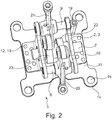
Figur 2 zeigt eine räumliche Ansicht auf das Trägermodul von oben. - Dargestellt ist in beiden Figuren ein stanz-biegetechnisch aus Stahlblech hergestelltes Trägermodul 1 für einen OHC-Ventiltrieb einer einzylindrigen Motorrad-Brennkraftmaschine.
- Das Trägermodul 1 hat zwei aufrechte und zueinander beabstandete Tragwände 2, welche über von deren Unterstirnen 4 orthogonal abgebogene Schenkel 10 auf einer separaten Grundplatte 11 stehen. Wie zu erkennen ist, ragen die Schenkel 10 voneinander weg. Sie sind an der Grundplatte 11 über in Bohrungen 13 sitzende Nietverbindungen 12 fixiert. Dabei sind nur eine Teilmenge der vorgefertigten Bohrungen mit Nietverbindungen 12 besetzt, so daß ohne eine Änderung der Grundplatte 11 und der Tragwände 2, lediglich durch seitlichen Versatz Letztgenannter auf der Grundplatte 11, das Trägermodul 1 in unterschiedlichen Brennkraftmaschinentypen verbaut werden kann.
- Jede Tragwand 2 hat eine in etwa mittige Hauptbohrung 5. In den Hauptbohrungen 5 ist eine Nockenwelle 7 drehbeweglich gelagert. Für einen ungehinderten Durchlauf von Nocken 22, 23 der Nockenwelle 7 ist in der Grundplatte 11 ein Fenster 18 vorgesehen.
- Jede Tragwand 2 hat zwei Nebenbohrungen 6. Letztgenannte liegen an laschenartig wegragenden Kantenbereichen 16 der Tragwand 2, bei deren Ober- zur Seitenstirn 3, 17. In jedem Paar von Nebenbohrungen 6 ist eine Ventilbetätigungshebelwelle 8, 9 gelagert, wobei die Ventilbetätigungshebelwelle 8 als Einlaßwelle fungiert und einen Einlaßkipphebel 20 trägt und wobei die Ventilbetätigungshebelwelle 9 als Auslaßwelle dient und einen Auslaßkipphebel 21 aufweist.
- Schließlich geht am besten aus
Figur 1 hervor, daß an der hier rechts ersichtlichen Tragwand 2 ein von der Unter- zur Oberstirn 4, 3 führendes Ölsteigröhrchen 19 angeklipst ist. Dieses dient im Betrieb der Brennkraftmaschine einer Weiterleitung von Schmierstoff in Richtung Zylinderkopfdeckel. -
- 1) Trägermodul
- 2) Tragwand
- 3) Oberstirn
- 4) Unterstirn
- 5) Hauptbohrung
- 6) Nebenbohrung
- 7) Nockenwelle
- 8) Ventilbetätigungshebelwelle (Einlaß)
- 9) Ventilbetätigungshebelwelle (Auslaß)
- 10) Schenkel
- 11) Grundplatte
- 12) Verbindung
- 13) Bohrung
- 14) Kante
- 15)Öffnung
- 16) Kantenbereich
- 17) Seitenstirn
- 18) Fenster
- 19) Ölsteigröhrchen
- 20) Einlaßkipphebel
- 21) Auslaßkipphebel
- 22) Nocken
- 23) Nocken
Claims (10)
- Trägermodul (1) für einen OHC-Ventiltrieb einer Brennkraftmaschine, mit zwei aufrechten und separaten Tragwänden (2), welche bei ihren Oberstirnen (3) zumindest mittelbar mit einem Zylinderkopfdeckel und bei ihren Unterstirnen (4) zumindest mittelbar mit einem Zylinderkopf verbindbar sind sowie jeweils wenigstens eine Haupt- und Nebenbohrung (5, 6) zur Lagerung einer Nocken- und Ventilbetätigungshebelwelle (7, 8, 9) hierzwischen aufweisen, und wobei von der Unterstirn (4) jeder Tragwand (2) ein orthogonal abgebogener Schenkel (10) absteht, der auf einer separaten, einer unmittelbaren Verbindung des Trägermoduls (1) mit dem Zylinderkopf dienenden Grundplatte (11) befestigt ist, wobei die Grundplatte (11) sowie die Tragwände (2) mit ihren Schenkeln (10) stanz-biegetechnisch aus Stahlblech dargestellt sind.
- Trägermodul nach Anspruch 1, dadurch gekennzeichnet, daß die Schenkel (10) der Tragwände (2) auf der Grundplatte (11) voneinander wegstehen.
- Trägermodul nach Anspruch 1, dadurch gekennzeichnet, daß die Schenkel (10) der Tragwände (2) an der Grundplatte (11) entweder a) über eine Schweiß- oder b) über eine Niet-, Stift- oder Schraubverbindung (12) fixiert sind.
- Trägermodul nach Anspruch 3, dadurch gekennzeichnet, daß, im Fall b), zur Ermöglichung eines Baukastens, wenigstens eines der Bauteile Schenkel (10) / Grundplatte (11) mehr Bohrungen (13) hat, als Niet-, Stift- oder Schraubverbindungen (12) gesetzt sind.
- Trägermodul nach Anspruch 1, dadurch gekennzeichnet, daß die Grundplatte (11) im Bereich ihrer Kanten (14) gestanzte Öffnungen (15) zum Verschrauben oder Zentrierverstiften des Trägermoduls (1) mit dem Zylinderkopf aufweist.
- Trägermodul nach Anspruch 1, dadurch gekennzeichnet, daß jede Tragwand (2) nur eine in ihre Längsrichtung gesehen in etwa mittige Hauptbohrung (5) aufweist, wobei die Nebenbohrungen (6) an beiden Kantenbereichen (16) der zwei Tragwände (2) bei deren Ober- zu Seitenstirnen (3, 17) liegen, so daß zwischen beiden Tragwänden (2) eine Nockenwelle (7) und zwei Ventilbetätigungshebelwellen (8, 9) vorsehbar oder vorgesehen sind.
- Trägermodul nach Anspruch 6, dadurch gekennzeichnet, daß die Kantenbereiche (16) der Tragwände (2) mit den Nebenbohrungen (6) laschenartig ausgeschnitten von den Tragwänden (2) wegragen.
- Trägermodul nach Anspruch 1, dadurch gekennzeichnet, daß ein Mittenbereich der Grundplatte (11) zwischen den Tragwänden (2) mit einem Fenster (18) oder einer Einsenkung versehen ist.
- Trägermodul nach Anspruch 1, dadurch gekennzeichnet, daß an zumindest einer der beiden Tragwände (2) wenigstens ein von der Unter- zur Oberstirn (4, 3) führendes, separates Ölsteigröhrchen (19) befestigt ist.
- Trägermodul nach Anspruch 1, dadurch gekennzeichnet, daß das Trägermodul (1) für einen Ventiltrieb einer einzylindrigen Brennkraftmaschine vorgesehen ist.
Applications Claiming Priority (2)
| Application Number | Priority Date | Filing Date | Title |
|---|---|---|---|
| DE102014210477.7A DE102014210477A1 (de) | 2014-06-03 | 2014-06-03 | Trägermodul |
| PCT/DE2015/200234 WO2015185044A1 (de) | 2014-06-03 | 2015-03-31 | Trägermodul |
Publications (2)
| Publication Number | Publication Date |
|---|---|
| EP3152413A1 EP3152413A1 (de) | 2017-04-12 |
| EP3152413B1 true EP3152413B1 (de) | 2018-09-19 |
Family
ID=53039143
Family Applications (1)
| Application Number | Title | Priority Date | Filing Date |
|---|---|---|---|
| EP15719603.1A Not-in-force EP3152413B1 (de) | 2014-06-03 | 2015-03-31 | Trägermodul |
Country Status (3)
| Country | Link |
|---|---|
| EP (1) | EP3152413B1 (de) |
| DE (1) | DE102014210477A1 (de) |
| WO (1) | WO2015185044A1 (de) |
Family Cites Families (4)
| Publication number | Priority date | Publication date | Assignee | Title |
|---|---|---|---|---|
| US4724804A (en) * | 1987-02-24 | 1988-02-16 | General Motors Corporation | Engine valve train module |
| DE602007003789D1 (de) * | 2006-09-25 | 2010-01-28 | Honda Motor Co Ltd | Verbrennungsmotor mit variabler Ventilhebung |
| DE102007063254A1 (de) * | 2007-12-31 | 2009-07-02 | Mahle International Gmbh | Zylinderkopfhaube |
| DE102011088994A1 (de) * | 2011-12-19 | 2013-06-20 | Bayerische Motoren Werke Aktiengesellschaft | Hubvariabler Ventiltrieb für einen Zylinderkopf einer Brennkraftmaschine |
-
2014
- 2014-06-03 DE DE102014210477.7A patent/DE102014210477A1/de not_active Withdrawn
-
2015
- 2015-03-31 EP EP15719603.1A patent/EP3152413B1/de not_active Not-in-force
- 2015-03-31 WO PCT/DE2015/200234 patent/WO2015185044A1/de not_active Ceased
Non-Patent Citations (1)
| Title |
|---|
| None * |
Also Published As
| Publication number | Publication date |
|---|---|
| WO2015185044A1 (de) | 2015-12-10 |
| EP3152413A1 (de) | 2017-04-12 |
| DE102014210477A1 (de) | 2015-12-03 |
Similar Documents
| Publication | Publication Date | Title |
|---|---|---|
| DE9405442U1 (de) | 4-Ventil-Kolbenbrennkraftmaschine | |
| DE102012213662A1 (de) | Kipphebel | |
| DE3805588A1 (de) | Ventilbetaetigungsmodul fuer eine brennkraftmaschine | |
| EP0861975A2 (de) | Abgaskrümmerflansch für eine Brennkraftmaschine | |
| DE102015200100B3 (de) | Trägermodul | |
| DE102014210477A1 (de) | Trägermodul | |
| DE19641811A1 (de) | Ventilanordnung für Verbrennungsmotoren | |
| EP3152414B1 (de) | Trägermodul | |
| EP3158172B1 (de) | Trägermodul fur einen ohc-ventiltrieb einer brennkraftmaschine | |
| DE102022003788A1 (de) | Nockenwelle für verbesserte Einstellung der Motorsteuerung | |
| DE102010034201B4 (de) | Rollenschlepphebel für eine Betätigung eines Gaswechselventils einer Brennkraftmaschine | |
| DE69623823T3 (de) | Zylinderkopfzusammenbau mit flachen und gegossenen komponenten | |
| EP3140520B1 (de) | Trägermodul | |
| EP3721089B1 (de) | Lamellenauslassventil | |
| EP2468432B1 (de) | Verfahren zum Herstellen einer Schaltkulisse | |
| DE202004004802U1 (de) | Vorrichtung zum Rückführen von Öl | |
| DE102013222820B4 (de) | Hubvariabler Ventiltrieb eines Verbrennungsmotors | |
| DE102014201247A1 (de) | Trägermodul für einen Ventiltrieb einer Brennkraftmaschine | |
| EP1445434B1 (de) | Verbrennungskraftmaschine mit Hubverstellung der Gaswechselventile | |
| DE102015222066A1 (de) | Kipphebel für Megamodelldesign | |
| DE102019120910A1 (de) | Kipphebel für einen Ventiltrieb einer Nutzfahrzeug-Brennkraftmaschine | |
| DE102011121587B4 (de) | Ventilgesteuerter Dampfexpander | |
| DE102023119070A1 (de) | Baueinheit für einen OHV-Ventiltrieb einer Schwerlastbrennkraftmaschine | |
| DE102015222632A1 (de) | Schlepphebel | |
| DE102018115149A1 (de) | Trägerleiste für das e-rocker-System |
Legal Events
| Date | Code | Title | Description |
|---|---|---|---|
| STAA | Information on the status of an ep patent application or granted ep patent |
Free format text: STATUS: THE INTERNATIONAL PUBLICATION HAS BEEN MADE |
|
| PUAI | Public reference made under article 153(3) epc to a published international application that has entered the european phase |
Free format text: ORIGINAL CODE: 0009012 |
|
| STAA | Information on the status of an ep patent application or granted ep patent |
Free format text: STATUS: REQUEST FOR EXAMINATION WAS MADE |
|
| 17P | Request for examination filed |
Effective date: 20170103 |
|
| AK | Designated contracting states |
Kind code of ref document: A1 Designated state(s): AL AT BE BG CH CY CZ DE DK EE ES FI FR GB GR HR HU IE IS IT LI LT LU LV MC MK MT NL NO PL PT RO RS SE SI SK SM TR |
|
| AX | Request for extension of the european patent |
Extension state: BA ME |
|
| DAV | Request for validation of the european patent (deleted) | ||
| DAX | Request for extension of the european patent (deleted) | ||
| GRAP | Despatch of communication of intention to grant a patent |
Free format text: ORIGINAL CODE: EPIDOSNIGR1 |
|
| STAA | Information on the status of an ep patent application or granted ep patent |
Free format text: STATUS: GRANT OF PATENT IS INTENDED |
|
| INTG | Intention to grant announced |
Effective date: 20180509 |
|
| GRAS | Grant fee paid |
Free format text: ORIGINAL CODE: EPIDOSNIGR3 |
|
| GRAA | (expected) grant |
Free format text: ORIGINAL CODE: 0009210 |
|
| STAA | Information on the status of an ep patent application or granted ep patent |
Free format text: STATUS: THE PATENT HAS BEEN GRANTED |
|
| AK | Designated contracting states |
Kind code of ref document: B1 Designated state(s): AL AT BE BG CH CY CZ DE DK EE ES FI FR GB GR HR HU IE IS IT LI LT LU LV MC MK MT NL NO PL PT RO RS SE SI SK SM TR |
|
| REG | Reference to a national code |
Ref country code: GB Ref legal event code: FG4D Free format text: NOT ENGLISH |
|
| REG | Reference to a national code |
Ref country code: CH Ref legal event code: EP |
|
| REG | Reference to a national code |
Ref country code: AT Ref legal event code: REF Ref document number: 1043489 Country of ref document: AT Kind code of ref document: T Effective date: 20181015 |
|
| REG | Reference to a national code |
Ref country code: IE Ref legal event code: FG4D Free format text: LANGUAGE OF EP DOCUMENT: GERMAN |
|
| REG | Reference to a national code |
Ref country code: DE Ref legal event code: R096 Ref document number: 502015005976 Country of ref document: DE |
|
| REG | Reference to a national code |
Ref country code: NL Ref legal event code: MP Effective date: 20180919 |
|
| PG25 | Lapsed in a contracting state [announced via postgrant information from national office to epo] |
Ref country code: NO Free format text: LAPSE BECAUSE OF FAILURE TO SUBMIT A TRANSLATION OF THE DESCRIPTION OR TO PAY THE FEE WITHIN THE PRESCRIBED TIME-LIMIT Effective date: 20181219 Ref country code: BG Free format text: LAPSE BECAUSE OF FAILURE TO SUBMIT A TRANSLATION OF THE DESCRIPTION OR TO PAY THE FEE WITHIN THE PRESCRIBED TIME-LIMIT Effective date: 20181219 Ref country code: SE Free format text: LAPSE BECAUSE OF FAILURE TO SUBMIT A TRANSLATION OF THE DESCRIPTION OR TO PAY THE FEE WITHIN THE PRESCRIBED TIME-LIMIT Effective date: 20180919 Ref country code: RS Free format text: LAPSE BECAUSE OF FAILURE TO SUBMIT A TRANSLATION OF THE DESCRIPTION OR TO PAY THE FEE WITHIN THE PRESCRIBED TIME-LIMIT Effective date: 20180919 Ref country code: GR Free format text: LAPSE BECAUSE OF FAILURE TO SUBMIT A TRANSLATION OF THE DESCRIPTION OR TO PAY THE FEE WITHIN THE PRESCRIBED TIME-LIMIT Effective date: 20181220 Ref country code: FI Free format text: LAPSE BECAUSE OF FAILURE TO SUBMIT A TRANSLATION OF THE DESCRIPTION OR TO PAY THE FEE WITHIN THE PRESCRIBED TIME-LIMIT Effective date: 20180919 Ref country code: LT Free format text: LAPSE BECAUSE OF FAILURE TO SUBMIT A TRANSLATION OF THE DESCRIPTION OR TO PAY THE FEE WITHIN THE PRESCRIBED TIME-LIMIT Effective date: 20180919 |
|
| REG | Reference to a national code |
Ref country code: LT Ref legal event code: MG4D |
|
| PG25 | Lapsed in a contracting state [announced via postgrant information from national office to epo] |
Ref country code: HR Free format text: LAPSE BECAUSE OF FAILURE TO SUBMIT A TRANSLATION OF THE DESCRIPTION OR TO PAY THE FEE WITHIN THE PRESCRIBED TIME-LIMIT Effective date: 20180919 Ref country code: LV Free format text: LAPSE BECAUSE OF FAILURE TO SUBMIT A TRANSLATION OF THE DESCRIPTION OR TO PAY THE FEE WITHIN THE PRESCRIBED TIME-LIMIT Effective date: 20180919 Ref country code: AL Free format text: LAPSE BECAUSE OF FAILURE TO SUBMIT A TRANSLATION OF THE DESCRIPTION OR TO PAY THE FEE WITHIN THE PRESCRIBED TIME-LIMIT Effective date: 20180919 |
|
| PG25 | Lapsed in a contracting state [announced via postgrant information from national office to epo] |
Ref country code: EE Free format text: LAPSE BECAUSE OF FAILURE TO SUBMIT A TRANSLATION OF THE DESCRIPTION OR TO PAY THE FEE WITHIN THE PRESCRIBED TIME-LIMIT Effective date: 20180919 Ref country code: IS Free format text: LAPSE BECAUSE OF FAILURE TO SUBMIT A TRANSLATION OF THE DESCRIPTION OR TO PAY THE FEE WITHIN THE PRESCRIBED TIME-LIMIT Effective date: 20190119 Ref country code: RO Free format text: LAPSE BECAUSE OF FAILURE TO SUBMIT A TRANSLATION OF THE DESCRIPTION OR TO PAY THE FEE WITHIN THE PRESCRIBED TIME-LIMIT Effective date: 20180919 Ref country code: NL Free format text: LAPSE BECAUSE OF FAILURE TO SUBMIT A TRANSLATION OF THE DESCRIPTION OR TO PAY THE FEE WITHIN THE PRESCRIBED TIME-LIMIT Effective date: 20180919 Ref country code: ES Free format text: LAPSE BECAUSE OF FAILURE TO SUBMIT A TRANSLATION OF THE DESCRIPTION OR TO PAY THE FEE WITHIN THE PRESCRIBED TIME-LIMIT Effective date: 20180919 Ref country code: PL Free format text: LAPSE BECAUSE OF FAILURE TO SUBMIT A TRANSLATION OF THE DESCRIPTION OR TO PAY THE FEE WITHIN THE PRESCRIBED TIME-LIMIT Effective date: 20180919 Ref country code: CZ Free format text: LAPSE BECAUSE OF FAILURE TO SUBMIT A TRANSLATION OF THE DESCRIPTION OR TO PAY THE FEE WITHIN THE PRESCRIBED TIME-LIMIT Effective date: 20180919 Ref country code: IT Free format text: LAPSE BECAUSE OF FAILURE TO SUBMIT A TRANSLATION OF THE DESCRIPTION OR TO PAY THE FEE WITHIN THE PRESCRIBED TIME-LIMIT Effective date: 20180919 |
|
| PG25 | Lapsed in a contracting state [announced via postgrant information from national office to epo] |
Ref country code: SK Free format text: LAPSE BECAUSE OF FAILURE TO SUBMIT A TRANSLATION OF THE DESCRIPTION OR TO PAY THE FEE WITHIN THE PRESCRIBED TIME-LIMIT Effective date: 20180919 Ref country code: SM Free format text: LAPSE BECAUSE OF FAILURE TO SUBMIT A TRANSLATION OF THE DESCRIPTION OR TO PAY THE FEE WITHIN THE PRESCRIBED TIME-LIMIT Effective date: 20180919 Ref country code: PT Free format text: LAPSE BECAUSE OF FAILURE TO SUBMIT A TRANSLATION OF THE DESCRIPTION OR TO PAY THE FEE WITHIN THE PRESCRIBED TIME-LIMIT Effective date: 20190119 |
|
| REG | Reference to a national code |
Ref country code: DE Ref legal event code: R097 Ref document number: 502015005976 Country of ref document: DE |
|
| PLBE | No opposition filed within time limit |
Free format text: ORIGINAL CODE: 0009261 |
|
| STAA | Information on the status of an ep patent application or granted ep patent |
Free format text: STATUS: NO OPPOSITION FILED WITHIN TIME LIMIT |
|
| PG25 | Lapsed in a contracting state [announced via postgrant information from national office to epo] |
Ref country code: DK Free format text: LAPSE BECAUSE OF FAILURE TO SUBMIT A TRANSLATION OF THE DESCRIPTION OR TO PAY THE FEE WITHIN THE PRESCRIBED TIME-LIMIT Effective date: 20180919 |
|
| 26N | No opposition filed |
Effective date: 20190620 |
|
| PG25 | Lapsed in a contracting state [announced via postgrant information from national office to epo] |
Ref country code: SI Free format text: LAPSE BECAUSE OF FAILURE TO SUBMIT A TRANSLATION OF THE DESCRIPTION OR TO PAY THE FEE WITHIN THE PRESCRIBED TIME-LIMIT Effective date: 20180919 Ref country code: MC Free format text: LAPSE BECAUSE OF FAILURE TO SUBMIT A TRANSLATION OF THE DESCRIPTION OR TO PAY THE FEE WITHIN THE PRESCRIBED TIME-LIMIT Effective date: 20180919 |
|
| REG | Reference to a national code |
Ref country code: CH Ref legal event code: PL |
|
| GBPC | Gb: european patent ceased through non-payment of renewal fee |
Effective date: 20190331 |
|
| PG25 | Lapsed in a contracting state [announced via postgrant information from national office to epo] |
Ref country code: LU Free format text: LAPSE BECAUSE OF NON-PAYMENT OF DUE FEES Effective date: 20190331 |
|
| REG | Reference to a national code |
Ref country code: BE Ref legal event code: MM Effective date: 20190331 |
|
| PG25 | Lapsed in a contracting state [announced via postgrant information from national office to epo] |
Ref country code: IE Free format text: LAPSE BECAUSE OF NON-PAYMENT OF DUE FEES Effective date: 20190331 Ref country code: CH Free format text: LAPSE BECAUSE OF NON-PAYMENT OF DUE FEES Effective date: 20190331 Ref country code: GB Free format text: LAPSE BECAUSE OF NON-PAYMENT OF DUE FEES Effective date: 20190331 Ref country code: LI Free format text: LAPSE BECAUSE OF NON-PAYMENT OF DUE FEES Effective date: 20190331 |
|
| PG25 | Lapsed in a contracting state [announced via postgrant information from national office to epo] |
Ref country code: FR Free format text: LAPSE BECAUSE OF NON-PAYMENT OF DUE FEES Effective date: 20190331 Ref country code: BE Free format text: LAPSE BECAUSE OF NON-PAYMENT OF DUE FEES Effective date: 20190331 |
|
| PG25 | Lapsed in a contracting state [announced via postgrant information from national office to epo] |
Ref country code: TR Free format text: LAPSE BECAUSE OF FAILURE TO SUBMIT A TRANSLATION OF THE DESCRIPTION OR TO PAY THE FEE WITHIN THE PRESCRIBED TIME-LIMIT Effective date: 20180919 |
|
| PG25 | Lapsed in a contracting state [announced via postgrant information from national office to epo] |
Ref country code: MT Free format text: LAPSE BECAUSE OF FAILURE TO SUBMIT A TRANSLATION OF THE DESCRIPTION OR TO PAY THE FEE WITHIN THE PRESCRIBED TIME-LIMIT Effective date: 20180919 |
|
| REG | Reference to a national code |
Ref country code: AT Ref legal event code: MM01 Ref document number: 1043489 Country of ref document: AT Kind code of ref document: T Effective date: 20200331 |
|
| PG25 | Lapsed in a contracting state [announced via postgrant information from national office to epo] |
Ref country code: CY Free format text: LAPSE BECAUSE OF FAILURE TO SUBMIT A TRANSLATION OF THE DESCRIPTION OR TO PAY THE FEE WITHIN THE PRESCRIBED TIME-LIMIT Effective date: 20180919 |
|
| PG25 | Lapsed in a contracting state [announced via postgrant information from national office to epo] |
Ref country code: HU Free format text: LAPSE BECAUSE OF FAILURE TO SUBMIT A TRANSLATION OF THE DESCRIPTION OR TO PAY THE FEE WITHIN THE PRESCRIBED TIME-LIMIT; INVALID AB INITIO Effective date: 20150331 |
|
| PG25 | Lapsed in a contracting state [announced via postgrant information from national office to epo] |
Ref country code: AT Free format text: LAPSE BECAUSE OF NON-PAYMENT OF DUE FEES Effective date: 20200331 |
|
| PG25 | Lapsed in a contracting state [announced via postgrant information from national office to epo] |
Ref country code: MK Free format text: LAPSE BECAUSE OF FAILURE TO SUBMIT A TRANSLATION OF THE DESCRIPTION OR TO PAY THE FEE WITHIN THE PRESCRIBED TIME-LIMIT Effective date: 20180919 |
|
| P01 | Opt-out of the competence of the unified patent court (upc) registered |
Effective date: 20230522 |
|
| PGFP | Annual fee paid to national office [announced via postgrant information from national office to epo] |
Ref country code: DE Payment date: 20230519 Year of fee payment: 9 |
|
| REG | Reference to a national code |
Ref country code: DE Ref legal event code: R119 Ref document number: 502015005976 Country of ref document: DE |
|
| PG25 | Lapsed in a contracting state [announced via postgrant information from national office to epo] |
Ref country code: DE Free format text: LAPSE BECAUSE OF NON-PAYMENT OF DUE FEES Effective date: 20241001 |
|
| PG25 | Lapsed in a contracting state [announced via postgrant information from national office to epo] |
Ref country code: DE Free format text: LAPSE BECAUSE OF NON-PAYMENT OF DUE FEES Effective date: 20241001 |