EP3151993B1 - Verfahren zum bearbeiten eines werkstücks, werkzeuganordnung und verzahnungsmaschine - Google Patents
Verfahren zum bearbeiten eines werkstücks, werkzeuganordnung und verzahnungsmaschine Download PDFInfo
- Publication number
- EP3151993B1 EP3151993B1 EP15727552.0A EP15727552A EP3151993B1 EP 3151993 B1 EP3151993 B1 EP 3151993B1 EP 15727552 A EP15727552 A EP 15727552A EP 3151993 B1 EP3151993 B1 EP 3151993B1
- Authority
- EP
- European Patent Office
- Prior art keywords
- workpiece
- toothing
- axis
- movement
- tool
- Prior art date
- Legal status (The legal status is an assumption and is not a legal conclusion. Google has not performed a legal analysis and makes no representation as to the accuracy of the status listed.)
- Active
Links
- 238000003754 machining Methods 0.000 title claims description 115
- 238000000034 method Methods 0.000 title claims description 73
- 238000005520 cutting process Methods 0.000 title claims description 60
- 238000010008 shearing Methods 0.000 claims description 26
- 238000005096 rolling process Methods 0.000 claims description 20
- 230000008859 change Effects 0.000 claims description 13
- 238000004519 manufacturing process Methods 0.000 claims description 13
- 239000000463 material Substances 0.000 claims description 10
- 238000007493 shaping process Methods 0.000 claims description 2
- 230000008569 process Effects 0.000 description 17
- 238000013461 design Methods 0.000 description 13
- 230000008878 coupling Effects 0.000 description 8
- 238000010168 coupling process Methods 0.000 description 8
- 238000005859 coupling reaction Methods 0.000 description 8
- 230000008901 benefit Effects 0.000 description 6
- 238000012545 processing Methods 0.000 description 5
- 230000007704 transition Effects 0.000 description 5
- 238000006073 displacement reaction Methods 0.000 description 4
- 238000010862 gear shaping Methods 0.000 description 4
- 230000002093 peripheral effect Effects 0.000 description 4
- 238000013459 approach Methods 0.000 description 3
- 229910000831 Steel Inorganic materials 0.000 description 2
- 239000010959 steel Substances 0.000 description 2
- 230000009471 action Effects 0.000 description 1
- 238000004458 analytical method Methods 0.000 description 1
- 230000015572 biosynthetic process Effects 0.000 description 1
- 239000011248 coating agent Substances 0.000 description 1
- 238000000576 coating method Methods 0.000 description 1
- 238000010924 continuous production Methods 0.000 description 1
- 238000011161 development Methods 0.000 description 1
- 230000000694 effects Effects 0.000 description 1
- 238000005516 engineering process Methods 0.000 description 1
- 230000003993 interaction Effects 0.000 description 1
- 230000004048 modification Effects 0.000 description 1
- 238000012986 modification Methods 0.000 description 1
- 230000000149 penetrating effect Effects 0.000 description 1
- 230000008092 positive effect Effects 0.000 description 1
- 239000011241 protective layer Substances 0.000 description 1
- 230000009467 reduction Effects 0.000 description 1
- 230000000717 retained effect Effects 0.000 description 1
- 238000012546 transfer Methods 0.000 description 1
- 238000011144 upstream manufacturing Methods 0.000 description 1
Images


Classifications
-
- B—PERFORMING OPERATIONS; TRANSPORTING
- B23—MACHINE TOOLS; METAL-WORKING NOT OTHERWISE PROVIDED FOR
- B23F—MAKING GEARS OR TOOTHED RACKS
- B23F21/00—Tools specially adapted for use in machines for manufacturing gear teeth
- B23F21/005—Tools specially adapted for use in machines for manufacturing gear teeth with plural tools on a common axis
-
- B—PERFORMING OPERATIONS; TRANSPORTING
- B23—MACHINE TOOLS; METAL-WORKING NOT OTHERWISE PROVIDED FOR
- B23F—MAKING GEARS OR TOOTHED RACKS
- B23F19/00—Finishing gear teeth by other tools than those used for manufacturing gear teeth
- B23F19/10—Chamfering the end edges of gear teeth
- B23F19/102—Chamfering the end edges of gear teeth by milling
-
- B—PERFORMING OPERATIONS; TRANSPORTING
- B23—MACHINE TOOLS; METAL-WORKING NOT OTHERWISE PROVIDED FOR
- B23F—MAKING GEARS OR TOOTHED RACKS
- B23F5/00—Making straight gear teeth involving moving a tool relatively to a workpiece with a rolling-off or an enveloping motion with respect to the gear teeth to be made
- B23F5/12—Making straight gear teeth involving moving a tool relatively to a workpiece with a rolling-off or an enveloping motion with respect to the gear teeth to be made by planing or slotting
- B23F5/16—Making straight gear teeth involving moving a tool relatively to a workpiece with a rolling-off or an enveloping motion with respect to the gear teeth to be made by planing or slotting the tool having a shape similar to that of a spur wheel or part thereof
- B23F5/163—Making straight gear teeth involving moving a tool relatively to a workpiece with a rolling-off or an enveloping motion with respect to the gear teeth to be made by planing or slotting the tool having a shape similar to that of a spur wheel or part thereof the tool and workpiece being in crossed axis arrangement, e.g. skiving, i.e. "Waelzschaelen"
-
- B—PERFORMING OPERATIONS; TRANSPORTING
- B23—MACHINE TOOLS; METAL-WORKING NOT OTHERWISE PROVIDED FOR
- B23F—MAKING GEARS OR TOOTHED RACKS
- B23F19/00—Finishing gear teeth by other tools than those used for manufacturing gear teeth
- B23F19/10—Chamfering the end edges of gear teeth
-
- B—PERFORMING OPERATIONS; TRANSPORTING
- B23—MACHINE TOOLS; METAL-WORKING NOT OTHERWISE PROVIDED FOR
- B23F—MAKING GEARS OR TOOTHED RACKS
- B23F21/00—Tools specially adapted for use in machines for manufacturing gear teeth
- B23F21/04—Planing or slotting tools
- B23F21/06—Planing or slotting tools having a profile which matches a gear tooth profile
-
- Y—GENERAL TAGGING OF NEW TECHNOLOGICAL DEVELOPMENTS; GENERAL TAGGING OF CROSS-SECTIONAL TECHNOLOGIES SPANNING OVER SEVERAL SECTIONS OF THE IPC; TECHNICAL SUBJECTS COVERED BY FORMER USPC CROSS-REFERENCE ART COLLECTIONS [XRACs] AND DIGESTS
- Y10—TECHNICAL SUBJECTS COVERED BY FORMER USPC
- Y10T—TECHNICAL SUBJECTS COVERED BY FORMER US CLASSIFICATION
- Y10T407/00—Cutters, for shaping
- Y10T407/17—Gear cutting tool
- Y10T407/1735—Rotary, gear shaving cutting tool
-
- Y—GENERAL TAGGING OF NEW TECHNOLOGICAL DEVELOPMENTS; GENERAL TAGGING OF CROSS-SECTIONAL TECHNOLOGIES SPANNING OVER SEVERAL SECTIONS OF THE IPC; TECHNICAL SUBJECTS COVERED BY FORMER USPC CROSS-REFERENCE ART COLLECTIONS [XRACs] AND DIGESTS
- Y10—TECHNICAL SUBJECTS COVERED BY FORMER USPC
- Y10T—TECHNICAL SUBJECTS COVERED BY FORMER US CLASSIFICATION
- Y10T409/00—Gear cutting, milling, or planing
- Y10T409/10—Gear cutting
- Y10T409/101113—Gear chamfering or deburring
- Y10T409/101272—Using relatively reciprocating or oscillating cutter
Definitions
- the invention relates to a method for machining a workpiece according to the preamble of claim 1, which is defined in document DE 10 2007 015 357 A1 is known, as well as a tool arrangement and a machine tool for carrying out the method.
- Such methods are known, for example by the skiving method, with which a toothing is produced in the first machining operation, and deburring, in which the burrs produced on the end face of the workpiece toothing are removed in the second machining operation carried out on the end face.
- the skiving process itself is known to those skilled in the art with regard to the design of the skiving wheels with the cutting edges formed on one side and the associated kinematics with the axis crossing angle between the tool axis of rotation and the workpiece axis of rotation EP 2 537 615 A1 referred, to which reference is made with regard to the design of the peeling wheels and the machine axis kinematics of the method.
- a method of the type mentioned is in the DE 10 2007 015 357 A1 disclosed, which describes the skiving to produce a toothing (first machining operation), and according to the deburring of the toothing produced is carried out with a deburring steel acting on the rear side of the toothing produced, which has the burrs, which is shown in the first two figures of DE 10 2007 015 357 A1 is shown and bears the reference number 23 there.
- DE 2 654 177 A1 discloses a peeling method in which a pre-cutter is connected upstream of the gear-producing peeling wheel.
- U.S. 2002/0197121 A1 discloses a sequential execution of deburring and gear finishing in the same workpiece clamping.
- DE 20 320 204 U1 discloses a chamfering tool arranged on the same axis as a helical hob.
- the object of the invention is to improve a method of the type mentioned at the beginning, in particular with regard to a higher machining quality that can be achieved in the second machining operation.
- the second engagement area can be positioned in relation to the workpiece by means of the same movement axes as the first engagement area and is movement-coupled to the first engagement area.
- the second machining intervention can also be carried out without changing the position and/or clamping of the machined workpiece, and also without requiring a tool change.
- the result is an advantageous interaction between the two machining interventions.
- the processing of the first processing intervention does not necessarily have to be completed before the second, "intermediate deburring" after a number of skiving strokes is also conceivable, for example.
- a change of location and/or clamping is not provided in a preferred variant of the method, but could be undertaken from other points of view, which will be explained further below.
- the second engagement area does not coincide with the first engagement area, but could definitely be a different area than the first engagement area of a structure supporting the first engagement area, as is also explained with reference to the preferred embodiments described below.
- the excess material on this axial side caused by the toothing production i.e. (primary) burrs, is removed by cutting off (shearing).
- neither before nor during the second machining operation is there a plastic deformation of the tooth edges of the workpiece toothing into a chamfer, in particular no action on the tooth edges of the toothing produced, as a result of which material is removed from the edge itself.
- toothing is to be interpreted with its movement-ending side in such a way that the latter does not necessarily have to be the axial end side of an "overall toothing". Rather, such an "overall toothing", for example an internal toothing, could have a transition from a higher to a deeper toothing, and at the transition there could also be an axial side into which the movement partially runs out. The same applies to a groove interrupting the toothing. Also here there is a gearing (gearing area) with a movement end side on which burrs occur during gearing production.
- the process is preferably used for workpieces with internal teeth, it can also be used to machine workpieces with external teeth.
- the first machining operation can also be carried out using the gear shaping method.
- the second engagement region is rotatable about an axis of rotation which, in the second machining engagement, runs coaxially to a tool spindle axis that runs coaxially to the axis of rotation of the cutting wheel in the first machining engagement.
- the first and the second engagement area can be rotationally coupled via the same axis of rotation. In this way, the second engagement area can also perform a rotational movement, as a result of which a better machining result of the second machining intervention can be achieved. In this way, burrs can be reliably removed.
- a compact machine design is possible, with the output of workpieces that have already been deburred.
- the second engagement area is formed by a toothing, in particular by a front side of a toothing.
- a toothing in particular by a front side of a toothing.
- the second engagement area can be on a deburring tool in the form of a disc, but also a deburring tool, a deburring needle or a deburring arrangement having such elements.
- the second engagement area lies behind the first engagement area with respect to the workpiece axis-parallel cutting movement direction component of the first machining intervention.
- the first engagement area would change accordingly in the case of motion-coupled engagement areas and, to the extent that the motion-ending Side of the workpiece toothing, which is the side facing the workpiece toothing clamping, come to lie closer to the workpiece clamping, and a corresponding spatial area would have to be kept free.
- the second engagement area is formed near the second end face of the cutting wheel, in particular formed by the cutting wheel teeth on this second end face.
- a particularly simple implementation of a tool arrangement suitable for the process is achieved in the form of a cutting wheel, the front side of which is used with the cutting edges provided there for toothing production (first engagement area and first machining engagement) and whose rear side (second engagement area) is the side of the workpiece toothing in the end of the movement second machining intervention processed.
- the second engagement area is formed on a second cutting wheel, which is in particular rigidly connected to the cutting wheel of the first machining operation and whose dimension in the direction of the cutting axis is in particular smaller than that of the first cutting wheel, preferably by at least 20%, in particular by at least 40 %.
- a tool suitable for this purpose could be designed as a tandem tool, ie a tool arrangement that carries the two tools and can be clamped onto a tool spindle.
- This variant offers the advantage of not being tied to the toothing geometry of the (first) cutting wheel for toothing production.
- the second cutting wheel is also toothed, preferably with a similar module, in particular the same module, as the first cutting wheel.
- the expression "second cutting wheel” is to be understood here as having a wheel-like shape and being capable of shearing off burrs, while the second cutting wheel does not require cutting edges to produce a toothing.
- a smaller axial dimension of the second wheel can exist, in particular, when machining is to be carried out on a side that is created by a groove or a transition between a higher and lower toothing and ends in movement.
- the axial dimension of the second wheel is suitably small for penetrating into a groove.
- the first cutting wheel could be equipped with the second engagement area on the back, and another wheel-shaped, in particular motion-coupled tool could be provided, the axial dimension of which is at least 20%, in particular at least 40%, and certainly 50% or more smaller than that of the first Cutting wheel, and which forms a (further second or) third engagement area on one end face, with which burrs occurring specifically in grooves or transitions in the toothing height on the workpiece can be eliminated.
- an outer diameter of the second engagement area in particular the addendum circle of a toothing of the second engagement area, is made to overlap with the root circle of the workpiece toothing during the second machining engagement. In this way, reliable burr removal can also take place in the foot area of the workpiece toothing.
- a flank area of the workpiece teeth is brought to overlap with a toothed flank area of the second engagement area.
- the toothing of the second engagement area rotates coupled to the rotation of the workpiece axis and the flank area of the workpiece toothing is brought to overlap with an envelope of rolling positions of a tooth of the second engagement area.
- burrs that have arisen as a result of the production of the workpiece toothing on the side that ends the movement are to be removed by shearing.
- a particularly preferred embodiment provides for the burrs to be sheared off by a shearing movement.
- the shearing movement is the burr-removing relative movement between the tool and the workpiece.
- the scalar product is preferred from the projected into the plane perpendicular to the workpiece axis and normalized to length one therein
- Direction vector of the shearing movement in the shearing point and the normal vector projected into the plane perpendicular to the workpiece axis and normalized therein to length one, standing in the shearing point on the workpiece flank and pointing to the gap is not greater than 0.5, preferably not greater than 0.3, more preferably not greater than 0.1, in particular not greater than 0, the shearing movement is therefore preferably directed away from a gap in the workpiece toothing, on one and in particular also the other of the tooth flanks delimiting the gap and including their tooth root areas.
- machining is carried out on the side of the left and right gear flanks one after the other, with the sequence not being important. This enables a more targeted machining of the underside of the workpiece toothing on the respective flank side and a correspondingly coordinated setting of the directional components of a shearing movement.
- the direction of rotation of the workpiece rotation is reversed during the second machining intervention between the machining on the left and on the right flank, in particular also a direction of rotation of the rotation of the second area of intervention. This also allows a flank-specific adjustment of a shearing direction of the shearing movement performed during deburring.
- the second engagement area is first positioned behind the movement end side of the workpiece toothing with respect to the cutting movement component parallel to the workpiece axis, then its distance from the workpiece axis is changed and the second engagement area for the second machining engagement is moved counter to the cutting movement component parallel to the workpiece axis.
- the center distance change to the workpiece axis is an increase if the generated gear is an internal gear and a reduction if it is an external gear.
- An approach down to exactly the level of the underside of the toothing (to surface contact) is not necessary, a minimum distance sufficient for shearing off the burrs can remain between the surfaces facing each other in the second machining operation.
- the axis of rotation of the workpiece and an axis of rotation of the second engagement area for the second machining engagement are driven in a predetermined speed ratio, in particular in the inverse ratio of the associated number of teeth (
- a region of the toothing profile can be brought to overlap with an envelope of rolling positions of a tooth of the second engagement region.
- This overlapping area can then be deburred in one workpiece cycle; several cycles are conceivable for an improved deburring result in this area.
- Such processing is also disclosed by the invention as an independent process worthy of protection, ie independent of the type of generation of the gearing and the availability of the same axes during deburring and/or the coupling to the gear-generating tool.
- the invention thus also relates to a method for machining an end face of a workpiece toothing, in which the workpiece toothing rotates about its workpiece axis and tool-side toothing is coupled in a rolling manner for the rotation of the workpiece axis rotating about its tool axis is brought into machining engagement with a front side facing the front side to be machined, so that excess material on the front side to be machined is sheared off.
- the machining intervention of this independent process design corresponds to the second machining intervention, which is used to remove burrs preferably without affecting the shape of the tooth edges.
- the features, settings and process designs presented above and below with regard to the second machining intervention also apply to this independently disclosed process design and can be combined with it or transferred to it.
- an additional rotation on the workpiece and/or tool side is performed for the second machining operation for overlapping and/or for changing the overlapping area.
- Such an additional rotation ultimately has the effect of a mutual displacement of the workpiece and the tool in the tangential direction.
- a relative movement with a directional component running radially to the workpiece axis is carried out in the second machining operation.
- a feed movement with a radial component is thus carried out, preferably in the direction of the tooth base of the machined toothing.
- a mutual change in position between the workpiece and one/the envelope of rolling positions of a tooth of the second engagement area is carried out, in particular the envelope is moved along a path having tangential and radial components.
- the envelope of the rolling positions of a tooth of the second engagement area viewed from the perspective of a gap in the gearing to be machined on its moving end side can be shifted in such a way that it follows the profile of the tooth gap, i.e. the Tooth flanks and the root area of the gap successively overlaps.
- the peripheral speed of the workpiece in the area in which deburring is currently taking place and which can change with radial infeed is approximately equal to the peripheral speed of the tool-side deburring edge.
- the speeds n 2 and n 0 can be adjusted during the in particular radial feed movement.
- approximately radial relative movement components of the momentarily acting deburring edges of the tool succeed.
- the speeds could be adjusted accordingly to achieve the same objective.
- the invention thus also relates to a method for machining an end face of a workpiece toothing as an independent method worthy of protection, in which the workpiece toothing rotates about its workpiece axis and a deburring tool rotating about its tool axis is brought into machining engagement with an engagement region facing the end face to be machined, so that material protrusions of the end face to be machined are sheared off in a shearing movement, wherein for at least 50%, preferably at least 70%, in particular at least 90% of the shearing points of the workpiece region machined in the machining engagement of each workpiece flank side, the scalar product from the projected into the plane perpendicular to the workpiece axis and therein to length one normalized directional vector of the shearing movement in the shearing point and the projected into the plane perpendicular to the workpiece axis and normalized to length one, standing in the shearing point on the workpiece flank and z normal vector pointing to the gap is not greater than 0.5, preferably not greater
- the machining intervention of this independent process design corresponds to the second machining intervention, which is used to remove burrs preferably without affecting the shape of the tooth edges.
- the respective peripheral speeds on the workpiece and tool side are coordinated with one another in the area just deburred, in particular in the form of essentially the same peripheral speeds.
- the deburring tool can be a toothed tool, but also, for example, a deburring disk or one or more rotating deburring steels.
- the movement axes (for positioning the first engagement area) have a first linear movement axis with a directional component parallel to the workpiece axis and a second linear movement axis with a directional component orthogonal to the first linear movement axis, and in particular a third linear movement axis with a directional component orthogonal to that of the first and second linear movement axes spanned level.
- the first linear movement axis can run parallel to the workpiece axis and the second linear movement axis can run orthogonally thereto. It is preferred that the first and second linear movement axes belong to the same movement axes, by means of which the second engagement area can be positioned with respect to the workpiece.
- the movement axes (with which the first engagement area can be positioned) have a rotary axis for setting an axis crossing angle between the workpiece axis and the cutting wheel axis.
- the axis intersection angle for the first and second machining can be loaded the same, which relieves the rotary machine axis.
- This rotary axis is required if the toothing on the workpiece is produced using the skiving process.
- the toothing on the workpiece could also be produced, for example, by gear shaping; in this case the rotary axis would not be necessary.
- the rotational axis as well as the third linear movement axis, if present for positioning the first engagement area do not have to belong to the available same movement axes for the second engagement area, but it can be preferred, particularly in the case of a movement and/or or rotational coupling of the first and second engagement areas.
- an orientation of a tool-side end face facing the end face of the workpiece teeth on the end of movement in the second machining operation is adapted to the orientation of the workpiece end face, in particular by means of tool shaping adapted to the machine axis settings in the second machining operation and/or by settings of the machine axes adapted to the tool shape in the second machining operation.
- the "and" variant of this "and/or” combination is to be understood in such a way that the tool shape and machine axis settings are coordinated with one another in the second machining operation in such a way that the orientation of the surfaces facing one another is adjusted accordingly, i.e. these are aligned in parallel in particular in order to to avoid unwanted collisions between the tool and the workpiece and, in particular, to avoid machining into the tooth flanks.
- the invention also relates to a tool arrangement according to independent claim 22.
- the second engagement area is formed by the cutting wheel teeth on its second end face.
- the tool arrangement can be formed as a single tool (with two different engagement areas).
- the second (a third) engagement area is formed on a second tool, in particular a toothed cutting wheel, which is axially spaced apart from the cutting wheel having the first engagement area.
- the invention also and in particular discloses as independently worthy of protection a tool arrangement with a cutting wheel having cutting edges on its toothing on a first end face, with which toothing can be produced on a workpiece, in particular in the skiving process , and a deburring tool rigidly coupled to the cutting wheel and rotatable about the same axis of rotation, in particular in the form of a toothing, the axial dimension of which is at least 20% less, preferably at least 40% less, in particular at least 60% less than that of the cutting wheel, for removing excess material (mere deburring) of axial side areas of the workpiece gearing.
- the second engagement area is ground. Furthermore, the second engagement area can be coated especially sanded before coating. These measures can have a positive effect in terms of reduced wear on the deburring tool.
- the machine can be designed as a gear shaping machine.
- the machine tool can have exactly one tool spindle and exactly one workpiece spindle, so that the method can be carried out, if necessary with a tool change, with a structurally simple machine.
- machine tool variants are also contemplated in which a location of the first machining operation and a location of the second machining operation differ to the extent that repositioning of the workpiece is necessary, with a positioning device that moves a clamped workpiece, in particular without changing its clamping, from the location of the first machining intervention to the location of the second machining intervention, for example by a rotary movement or also by a linear movement, which can be used, for example, in pick-up machines in which a suspended workpiece spindle moves linearly on the stand and the tool spindles are arranged below.
- the machine tool of this type is designed to machine a workpiece at one location in the first machining operation and another workpiece at another location in the second machining operation.
- this positioning results in a second clamping that is in particular diametrically opposed the location for the first processing intervention.
- Such a machine has at least two workpiece spindles, which are moved, for example, during the positioning movement of the clamping or are uncoupled before the positioning movement and then coupled.
- the position change could also be carried out by a loading/unloading system, with stationary spindles and clamping.
- the first, second and third linear movement axes and rotary axes explained above can be used as machine axes on the tool side in particular at the location(s) of the first/second machining operation, in addition to the rotary axes of the respective spindles themselves.
- these movement axes can be equipped with respective drives, e.g. in the form of servo drives, in particular direct drives, CNC-controlled via the control device.
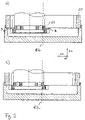
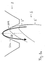
- FIG. 1a An embodiment of the method according to the invention is in 1 and 2 shown.
- a workpiece 20 in the form of an internally toothed gear wheel with internal teeth 2 is provided.
- the workpiece 20 is clamped in the usual way on a workpiece spindle with an axis of rotation C1, with a workpiece axis Z2 running vertically in this exemplary embodiment. Details of the clamping are not shown for the sake of clarity, the workpiece 20 appears only on a support 30 of the workpiece clamping.
- the internal toothing 2 is produced with a peeling wheel 10 which, with respect to its wheel axis Z0, has a toothing 4 on its circumferential surface remote from the clamping.
- the peeling wheel 10 rotates about the wheel axis Z0, which coincides with the rotary axis of rotation B1 of a tool spindle, not shown, in rolling coupling with the rotation of the workpiece 20 about the workpiece axis Z2.
- the viewing direction of the representation of Fig. 1a is that of a radial axis X1, with respect to which the tool 10 and the workpiece 20 can be moved relative to one another in order to set a desired axial distance relative to one another.
- a radial axis X1 with respect to which the tool 10 and the workpiece 20 can be moved relative to one another in order to set a desired axial distance relative to one another.
- the axis crossing angle ⁇ can be adjusted by a rotary axis A1, which can be implemented in the form of a rotation about an axis parallel or coaxial to the radial axis X1.
- Power skiving can also be carried out with a side offset and/or with a cylindrical tool.
- the peeling wheel 10 On the end face of the peeling wheel toothing 4 which is remote from the clamping process, its tooth edges 6 form the engagement area which acts in a cutting manner during the skiving of the toothing 2 .
- the peeling wheel 10 is advanced in one or more strokes after a corresponding radial infeed along the workpiece axis Z2, towards the end of the movement of the toothing 2, in which in 1 illustrated case from top to bottom along the workpiece axis Z2.
- This movement-ending axial end face of the toothing 2 is in Fig. 1b denoted by the reference numeral 3.
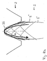
- the peeling wheel 10 is designed in such a way that, in a second machining operation, the side 3 of the toothing 2 which is running out of movement is machined in order to shear off the burrs protruding on this side 3 of the toothing.
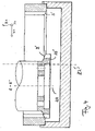
- the positioning of the peeling wheel 10 in the in Figure 2b is possible using control information that is already available for the Z2-axis-parallel movement.
- the deburring intervention could also be detected by sensors, for example via an acoustic sensor or a removal rate through the deburring that can be identified via the spindle axes B1 or C1 or the feed axis, or also via an analysis of the vibration behavior of the machine.
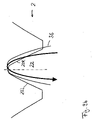
- Figure 3a shows Figure 3a in axial section that already in 1 and 2 shown peeling wheel 10, in which the rear end face 8 of the toothing 4 is formed planar, ie orthogonal to the peeling wheel axis Z0.
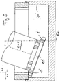
- FIG. 3b Another peeling wheel 10' is shown in axial section, the rear face 8' of which is formed, eg ground, at an angle to the peeling wheel axis Z0, which deviates from 90°.
- the design of the second engagement area in this case the rear face 8 of the peeling wheel, can be used to create suitable collision-free positional relationships between the surfaces 3, 8 of the workpiece and tool facing one another during the second machining intervention (here deburring).
- axis adjustments to achieve the collision-free mutual position of these surfaces 3, 8 can be used.
- a combination of these variants is not shown, but is also possible, in which, for example, a surface 3 is inclined or even partly due to an inclination of the rear end face 8 of the peeling wheel toothing 4 and partially by setting a crossed axis angle.
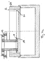
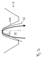
- gear shaping one would use the in 4 prefer the variant shown.
- FIG. 3c shows yet another variant in which, with a view to an in 6 shown engagement situation of the end face 3" of the workpiece toothing 2 running out of movement, the rear end face 8" is adapted in sections, wherein in this representative embodiment an outer section 8"p is formed planarly, while an adjoining section 8"k is conical in order to 6 to carry out the second machining operation shown without a collision, by the inclination of the second section 8"k being matched to that of the inner section of the lower end face 3".
- the in the Figures 3a to 3c The peeling wheels 10, 10' and 10" shown are conically shaped, but one could also use cylindrical peeling wheels.
- the toothing on the side of the peeling wheel toothing 4 forming the engagement area for the production of the toothing 2 with the cutting tooth edges 6 can be used as usual with helical toothing of the peeling wheel also be formed in the step cut, the invention is not further restricted in this respect.
- the second intervention area, in the example of the 3 the rear end faces 8, 8', 8" of the peeling wheel toothing 4 can be ground for an advantageous deburring result and also be provided with a protective layer in order to increase the durability of the second engagement area.
- the tooth edges formed on the rear end face 8 can also be rounded to reduce wear and tear.
- the chamfer formed on the outer diameter towards the back of the peeling wheel in conventional peeling wheels does not exist, but rather the outer diameter extends along a straight line when in Course along the axis of the peeling wheel is considered, since such a chamfer would make the intended deburring course more difficult.
- the tool is designed as a tandem tool and has, on the one hand, a peeling wheel 10 which, for example, has the shape of the Figures 3a to 3c peeling wheels shown can assume in which in the Figures 7a to 7c shown embodiment is about the variant of Figure 3a used, and on the other hand a spaced apart from this peeling wheel 10 further deburring tool 11, wherein the tandem tool 10, 11 represents a tool arrangement rigidly coupled with respect to common rotation.
- a second toothing could be provided on the deburring tool 11, which is arranged closer to the tool clamping than the peeling wheel itself (not shown), i.e.
- a toothing independent of the peeling wheel toothing 4 which carries the first engagement area.
- an independent tooth design is possible, so that the two engagement areas can be optimized independently of one another for the respective machining engagement.
- the area to be deburred on the rear could be ground conically on the circumference and/or backed concavely on the front side in order to create a suitable deburring geometry.
- a second engagement area closer to the tool clamping is not toothed, but rather forms an untoothed deburring disk, for example.
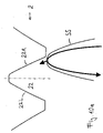
- Figures 8a to c schematically illustrate the formation of an overlapping area for a second machining operation that allows deburring.
- Figure 8a the rolling movement of a tooth 5 of a deburring toothing, viewed from the perspective of a gap 22 of a workpiece toothing 2, which is an internal toothing here.
- the direction of rotation of the deburring tool and the workpiece is anti-clockwise.
- This representation in projection onto a normal plane to the workpiece axis illustrates ( Figure 8b ) that the snapshots 5', 5", ... of the tooth 5 during the rolling movement form an enveloping curve 55 which is revealed from the outer contour of all rolling positions 5', 5", ... with respect to the gap 22.
- This enveloping curve 55 is in Figure 8c alone, ie without showing the individual rolling positions 5', 5", ... of the tooth 5.
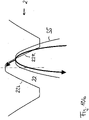
- Figure 9a shows Figure 9a a positioning of the enveloping curve 55 by radial delivery of the deburring tool relative to the gap 22 of the toothing 2 in the same representation as that of FIG Figures 8a to 8c ,
- the deburring tool end face being spaced apart from the toothing end face 3 to be deburred and lying opposite this.
- Corresponding intermediate position (tool tip circle overlaps workpiece root circle, tool root circle does not overlap workpiece tip circle) out follows a displacement of the enveloping curve 55 with respect to the tooth gap 22 in such a way that the in Figure 9b positional relationship shown is established, in which the overlapping area includes the right flank 22R of the tooth gap 22 and a part of the root area thereof.
- the positioning movement required for this can be achieved by linear movement axes, for example by the tangential linear movement axis Y, or by rotating the tool and workpiece against one another, for example by applying an additional rotation ⁇ B1 or ⁇ C1 or a combination of these types of movement.
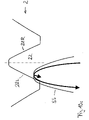
- the toothing end face 3 could be deburred on the left flanks 22L (and the left-hand flank root area) in the same way, as in 9c is shown by the overlap area compared to the figures 8c is not shifted to the right, but to the left, with the reference to the description of the Figure 9b indicated movement axes. It can be seen that in this way a sufficient overlap of the envelope 55 of the rolling movement positions 5', 5", ... of a tool tooth 5 with the respective flank 22R, 22L and the base of the face 3 of the toothing 2 to be deburred is achieved. so that the burr present there as excess material is completely sheared off. If necessary, the tool should be allowed to dwell in the respective deburring position for a certain amount of time. Of course, the order right flank - left flank can be reversed, and the exact way of displacement can also be modified The directions of rotation of toothing 2 and tool can be reversed.
- the shearing movement for the deburring is preferably adjusted in such a way that one in the plane of the paper figures 8 and 9 lying and normal to the toothing flank of the workpiece toothing is directed away from the shearing motion component of the shearing movement, ie is sheared from the gap to the gearing material.
- provision can be made to reverse the direction of rotation of the tool and workpiece before the in 9c shown relative position is taken.
- the toothing 4 to be deburred and the toothing 2 being deburred can rotate together counterclockwise or clockwise (in the case of internal teeth to be deburred), with the directions of rotation of the tool and workpiece being opposite to one another in the case of external teeth to be deburred are in order to obtain the rolling coupling.
- the overlapping area can also be enlarged to such an extent that the deburring takes place on both sides of the gap at the same time by means of a deeper radial infeed.
- the toothing of the tool can also be adjusted in such a way that complete deburring of the entire gap is already achieved by a radial infeed alone.
- FIG. 10a to 10c a variant is shown in which the enveloping curve 55 is moved with respect to the gap 22 of the toothing 2 along a predetermined path.
- the direction of rotation of the tool and the workpiece is anti-clockwise, and the axial infeed (Z1) causes them to engage in machining opposite toothing end faces 3, 8 are brought closer to the axial machining proximity, and the enveloping curve 55 is converted into the in Figure 10a position shown, near the addendum circle of the right flank 22R of the gap 22 of the toothing 2.
- Gear cutting machine 100 which is specially designed for skiving, has on its machine bed 60 a workpiece spindle (table spindle) with axis of rotation C1, on which an externally or internally toothed workpiece can be clamped with conventional clamping devices.
- a radial slide 62 that can be moved in the radial direction X1 on the machine bed 60, which is constructed like a tower and carries a vertical slide 64 on a side facing the workpiece spindle, which can be moved relative to the radial slide 62 parallel to the axis of the workpiece spindle with the direction of movement Z1.
- the vertical slide 64 in turn carries a tangential slide 66, which is mounted rotatably about an axis parallel to the radial axis X1, so that a cross-axis angle ⁇ between the workpiece axis and the tool axis can be set by the rotary movement A1.
- the movement axis Y1 of the tangential slide 66 is orthogonal to the radial movement axis X1 and the vertical movement axis Z1.
- a tool head 68 Arranged on the tangential slide 66 is a tool head 68 with an axis of rotation B1 defining tool spindle for receiving a cutting wheel, such as skiving tool and / or a deburring tool, wherein the deburring tool can also be present as a tandem tool.
- a cutting wheel such as skiving tool and / or a deburring tool
- FIG. 12 shows a schematic top view of a machine design, in which a not shown, in order to 12 axis of rotation C1 shown can be machined by a tool of a tool block 100A, which, for example, like the tool-side portion of the in 11 illustrated single-spindle machine can be constructed.
- a second tool-side block 100B is provided diametrically opposite, which functionally can be constructed like the tool block 100A, i.e. with regard to the position of the in 12 drawn workpiece axis of rotation C1 'can have the same movement axes.
- the rotary positioning unit 200 which has the clampings for the rotary axes C1, C1′ and, in particular, has the corresponding workpiece spindle axes rotatably coupled, can be rotated by 180°, in 12 on the left, for example, the skiving process is carried out and a toothing is thereby produced on a workpiece, while on the in 12 right position, the deburring operation can take place according to one or more of the process aspects explained above.
- the tool block 100A is equipped with a skiving wheel
- the tool block 100B is equipped with a deburring tool according to one of the deburring tool configurations explained above.
- a controller of the tool block 100B can control the deburring method according to one of the above method aspects with regard to deburring.
- Workpiece changers are not shown, which can be arranged, for example, in such a way that the respective workpieces are changed after deburring on the tool block 100B in the rotary position of the rotary positioning plate 200, which is shown in FIG 12 are spanned around the axis of rotation C1'.
- a machine configured in this way can functionally replace two individual machines with regard to machining, but still has the advantage of via the rotary positioning plate 200 coupled loading and unloading of the workpieces, which can take place parallel to the machining of other workpieces on the tool blocks 100A, 100B in the 90° positions without requiring a corresponding double space requirement.
- the two tool blocks 100A, 100B could be machined differently in the operating mode described above.
- a loading and unloading system can be used, which can transfer workpieces to and from the rotary positioning plate 200 both in the 180° position and in the 90° position.
Landscapes
- Engineering & Computer Science (AREA)
- Mechanical Engineering (AREA)
- Gear Processing (AREA)
Applications Claiming Priority (2)
| Application Number | Priority Date | Filing Date | Title |
|---|---|---|---|
| DE102014008475.2A DE102014008475B4 (de) | 2014-06-05 | 2014-06-05 | Verfahren zum Bearbeiten eines Werkstücks, Werkzeuganordnung und Verzahnungsmaschine |
| PCT/EP2015/001041 WO2015185186A1 (de) | 2014-06-05 | 2015-05-21 | Verfahren zum bearbeiten eines werkstücks, werkzeuganordnung und verzahnungsmaschine |
Publications (2)
| Publication Number | Publication Date |
|---|---|
| EP3151993A1 EP3151993A1 (de) | 2017-04-12 |
| EP3151993B1 true EP3151993B1 (de) | 2022-09-28 |
Family
ID=53365959
Family Applications (1)
| Application Number | Title | Priority Date | Filing Date |
|---|---|---|---|
| EP15727552.0A Active EP3151993B1 (de) | 2014-06-05 | 2015-05-21 | Verfahren zum bearbeiten eines werkstücks, werkzeuganordnung und verzahnungsmaschine |
Country Status (8)
| Country | Link |
|---|---|
| US (1) | US10583507B2 (ko) |
| EP (1) | EP3151993B1 (ko) |
| JP (1) | JP6527890B2 (ko) |
| KR (1) | KR101995784B1 (ko) |
| CN (1) | CN106457431B (ko) |
| DE (1) | DE102014008475B4 (ko) |
| ES (1) | ES2928786T3 (ko) |
| WO (1) | WO2015185186A1 (ko) |
Families Citing this family (25)
| Publication number | Priority date | Publication date | Assignee | Title |
|---|---|---|---|---|
| EP2954967B1 (de) * | 2014-06-11 | 2019-08-07 | Klingelnberg AG | Verfahren und Vorrichtung zum stirnseitigen Anfasen einer Verzahnung eines Werkstücks |
| DE102014218082B4 (de) * | 2014-09-10 | 2016-11-10 | Felsomat Gmbh & Co. Kg | Vorrichtung zur Wälzschälbearbeitung eines Werkstücks zur Fertigung einer Fase und zugehöriges Betriebsverfahren |
| DE102015104242A1 (de) * | 2015-03-20 | 2016-09-22 | Profilator Gmbh & Co. Kg | Verzahnungsverfahren mit Zahnnachbearbeitung |
| DE102015121821A1 (de) * | 2015-12-15 | 2017-06-22 | Profilator Gmbh & Co. Kg | Vorrichtung und Verfahren zur Fertigung einer Fase an einem verzahnten Werkrad |
| JP6720543B2 (ja) * | 2016-01-14 | 2020-07-08 | アイシン精機株式会社 | 歯車加工方法 |
| JP6693290B2 (ja) * | 2016-06-20 | 2020-05-13 | 株式会社ジェイテクト | 歯切り工具、砥石車、歯切り工具の設計方法、砥石車の設計方法及び工作機械 |
| US10618125B2 (en) * | 2016-07-01 | 2020-04-14 | Jtekt Corporation | Gear cutting tool, gear machining device, and gear machining method |
| DE102017204891A1 (de) * | 2017-03-23 | 2018-09-27 | Felsomat Gmbh & Co. Kg | Verfahren zum kombinierten Wälzschälanfasen und Feilen eines Werkstücks |
| DE102017112416A1 (de) | 2017-06-06 | 2018-12-06 | Liebherr-Verzahntechnik Gmbh | Vorrichtung und Verfahren zum Anfasen eines innenverzahnten Werkstücks |
| DE102017112450A1 (de) | 2017-06-06 | 2018-12-06 | Liebherr-Verzahntechnik Gmbh | Vorrichtung und Verfahren zum Anfasen eines innenverzahnten Werkstücks |
| DE102017006553A1 (de) * | 2017-07-11 | 2019-01-17 | Gleason-Pfauter Maschinenfabrik Gmbh | Verfahren zum Bearbeiten einer Verzahnung und dazu hergerichtete Verzahnungsmaschine |
| DE102017006651A1 (de) * | 2017-07-13 | 2019-01-17 | Gleason-Pfauter Maschinenfabrik Gmbh | Verfahren zum Erzeugen eines verzahnten Werkstücks |
| DE102018117368A1 (de) * | 2017-07-21 | 2019-01-24 | Jtekt Corporation | Bearbeitungsgerät und bearbeitungsverfahren |
| DE102018108632A1 (de) * | 2018-04-11 | 2019-10-17 | Liebherr-Verzahntechnik Gmbh | Vorrichtung zur Anfasbearbeitung eines Werkstücks |
| DE102019110481A1 (de) * | 2019-04-23 | 2020-10-29 | Profilator Gmbh & Co. Kg | Verfahren und Vorrichtung zum Herstellen von verzahnten Werkstücken, insbesondere Schiebemuffen |
| CH715794B8 (de) | 2019-07-17 | 2020-11-13 | Reishauer Ag | Werkzeugmaschine für die Wälzbearbeitung von Rotationsteilen mit nutförmigen Profilen. |
| DE102019131266A1 (de) * | 2019-11-20 | 2021-05-20 | Schaeffler Technologies AG & Co. KG | Verfahren und Vorrichtung zum Entgraten eines innenverzahnten Werkstücks |
| DE102020001428A1 (de) | 2020-03-05 | 2021-09-09 | Gleason-Pfauter Maschinenfabrik Gmbh | Verfahren zur Zahnkantenbearbeitung |
| JP7227428B2 (ja) * | 2020-04-03 | 2023-02-21 | オーエスジー株式会社 | 歯車の面取り方法 |
| DE102020111838A1 (de) * | 2020-04-30 | 2021-11-04 | Präwema Antriebstechnik GmbH | Verfahren zum Bearbeiten des Kopfkreisdurchmessers und Werkzeug zum Erzeugen eines Zahnrads |
| DE102020118384A1 (de) | 2020-07-13 | 2022-01-13 | Profilator Gmbh & Co. Kg | Vorrichtung und Verfahren zur Erzeugung von Fasen an Zahnflanken von Zahnrädern |
| DE102021108379A1 (de) * | 2021-04-01 | 2022-10-06 | Präwema Antriebstechnik GmbH | Wälzschälwerkzeug und verfahren zum wälzschälbearbeiten eines zahnradrohlings |
| DE102022117192A1 (de) * | 2022-07-11 | 2024-01-11 | Präwema Antriebstechnik GmbH | Werkzeug und Verfahren zum spanenden Entgraten und/oder Anfasen einer eine Mehrzahl von Werkstückzähnen umfassenden Werkstückverzahnung |
| DE102022003508A1 (de) | 2022-09-23 | 2024-03-28 | Nsh Technology Gmbh | Wälzschälmaschine und Verfahren zum Betrieb einer derartigen Wälzschälmaschine |
| DE102023000941A1 (de) | 2023-03-13 | 2024-09-19 | Gleason-Pfauter Maschinenfabrik Gmbh | Verzahnungsbearbeitung durch wälzschälen, hartschälen oder wälzstossen, und entsprechendes verzahnungswerkzeug |
Family Cites Families (16)
| Publication number | Priority date | Publication date | Assignee | Title |
|---|---|---|---|---|
| DE2654177A1 (de) * | 1976-11-30 | 1978-06-01 | Zahnradfabrik Friedrichshafen | Schaelwerkzeug zum bearbeiten von innen- und aussenverzahnten stirnraedern |
| US4739682A (en) * | 1986-07-03 | 1988-04-26 | Birkestrand Orville J | Tube end finishing machine |
| CH679465A5 (ko) * | 1989-08-25 | 1992-02-28 | Maag Zahnraeder & Maschinen Ag | |
| DE4122460C1 (ko) * | 1991-07-06 | 1992-04-23 | Praewema Werkzeugmaschinenfabrik Gmbh, 3440 Eschwege, De | |
| US20020081163A1 (en) * | 2000-12-21 | 2002-06-27 | Courtney Joseph A. | Stroking speed adjustment for shaping machine |
| US6840720B2 (en) | 2001-06-21 | 2005-01-11 | The Gleason Works | Machine for deburring and fine machining of tooth flanks of toothed workpieces |
| DE20320294U1 (de) * | 2003-07-05 | 2004-04-15 | Fette Gmbh | Vorrichtung zur Herstellung eines Zahnrads |
| DE202004008263U1 (de) * | 2004-05-19 | 2004-08-12 | Klingelnberg Gmbh | Entgratmesser, Vorrichtung zur Aufnahme von Entgratmessern und Kegelrad-Verzahnmaschine zum Anfassen und/oder Entgraten eines Kegelrades |
| DE102005049528A1 (de) * | 2005-10-17 | 2007-05-10 | Profilator Gmbh & Co. Kg | Verfahren zum Herstellen von Schiebemuffen |
| DE102007015357B4 (de) | 2007-03-30 | 2023-03-23 | Profilator Gmbh & Co. Kg | Verfahren und Vorrichtung zum Verzahnen von Werkstücken durch Wälzschälen und zugehöriger Schneidvorrichtung |
| DE102010009173A1 (de) | 2010-02-24 | 2011-08-25 | Otto Egelhof GmbH & Co. KG, 70736 | Ventil zur Steuerung eines Strömungskanales |
| DE102011009027A1 (de) * | 2011-01-20 | 2012-07-26 | Gleason-Pfauter Maschinenfabrik Gmbh | Verfahren zum spanenden Bearbeiten eines Werkstückes und dazu ausgelegte Werkzeugmaschine |
| JP2012171020A (ja) * | 2011-02-17 | 2012-09-10 | Aisin Seiki Co Ltd | 歯車製造方法 |
| EP2537615B1 (de) | 2011-06-21 | 2014-11-26 | Klingelnberg AG | Robustes Verfahren zum Wälzschälen |
| JP6212876B2 (ja) * | 2013-02-15 | 2017-10-18 | アイシン精機株式会社 | 歯車加工方法及び歯車加工用カッター |
| CN103406602A (zh) * | 2013-07-08 | 2013-11-27 | 上海三一精机有限公司 | 一种同步倒棱装置及滚齿机 |
-
2014
- 2014-06-05 DE DE102014008475.2A patent/DE102014008475B4/de active Active
-
2015
- 2015-05-21 JP JP2016571294A patent/JP6527890B2/ja active Active
- 2015-05-21 WO PCT/EP2015/001041 patent/WO2015185186A1/de active Application Filing
- 2015-05-21 CN CN201580029917.7A patent/CN106457431B/zh active Active
- 2015-05-21 ES ES15727552T patent/ES2928786T3/es active Active
- 2015-05-21 EP EP15727552.0A patent/EP3151993B1/de active Active
- 2015-05-21 US US15/310,584 patent/US10583507B2/en active Active
- 2015-05-21 KR KR1020167034307A patent/KR101995784B1/ko active IP Right Grant
Also Published As
| Publication number | Publication date |
|---|---|
| WO2015185186A1 (de) | 2015-12-10 |
| JP2017520416A (ja) | 2017-07-27 |
| DE102014008475B4 (de) | 2023-02-23 |
| US20170072485A1 (en) | 2017-03-16 |
| ES2928786T3 (es) | 2022-11-22 |
| JP6527890B2 (ja) | 2019-06-05 |
| KR20170012299A (ko) | 2017-02-02 |
| KR101995784B1 (ko) | 2019-07-03 |
| CN106457431A (zh) | 2017-02-22 |
| DE102014008475A1 (de) | 2015-12-17 |
| US10583507B2 (en) | 2020-03-10 |
| CN106457431B (zh) | 2020-01-10 |
| EP3151993A1 (de) | 2017-04-12 |
Similar Documents
| Publication | Publication Date | Title |
|---|---|---|
| EP3151993B1 (de) | Verfahren zum bearbeiten eines werkstücks, werkzeuganordnung und verzahnungsmaschine | |
| EP2665574B1 (de) | Verfahren des wälzschälens oder hartschälens eines werkstückes und dazu ausgelegte werkzeugmaschine | |
| EP2385885B1 (de) | Vorrichtung und verfahren zum verzahnen von werkstücken sowie zugehöriges werkzeugset | |
| EP2823924B1 (de) | Doppelabrichter | |
| EP3230001B1 (de) | Verfahren zum bearbeiten einer verzahnung, werkzeuganordnung und verzahnungsmaschine | |
| EP3188868B1 (de) | Verzahnungsbearbeitungsanordnung und verfahren zum bearbeiten einer verzahnung, bearbeitungswerkzeug und werkzeugmaschine | |
| EP3546101B1 (de) | Verfahren und vorrichtung zum verzahnen von werkrädern durch wälzschälen | |
| EP3191248A1 (de) | Verfahren zur wälzschälbearbeitung eines werkstücks zur fertigung einer fase | |
| EP2255910A1 (de) | Verzahnmaschine | |
| EP3651925B1 (de) | Verfahren zum erzeugen eines verzahnten werkstücks, sowie dazu geeignete steuerprogramm, wekzeuge und verzahnungsmaschine | |
| EP0665076B1 (de) | Verfahren zum Feinbearbeiten von Zahnrädern und dafür geeignetes innenverzahntes Werkzeug sowie Verfahren zum Abrichten dieses Werkzeugs und dafür geeignetes Abrichtrad | |
| EP3388179A1 (de) | Verfahren zur verzahnbearbeitung eines werkstücks | |
| EP3552745B1 (de) | Verfahren zum entgrat-bürsten von zahnrädern und cnc-verzahnmaschine mit einer entsprechenden software zum entgrat-bürsten | |
| DE202016103064U1 (de) | Vorrichtung zur spanenden Bearbeitung eines rotierenden Werkstücks | |
| DE805344C (de) | Nach dem Abwaelzverfahren arbeitende Verzahnungsmaschine | |
| EP2851150B1 (de) | Werkzeug, Verfahren und Maschine zum Erzeugen eines Verzahnungsprofils an einem Werkstück durch Wälzschälen | |
| EP3651924B1 (de) | Verfahren zum bearbeiten einer verzahnung und dazu hergerichtete verzahnungsmaschine, sowie computerprogrammprodukt dafür | |
| EP0568849B1 (de) | Verfahren zum Feinbearbeiten von balligen und/oder konischen Verzahnungen und zur Ausführung dieses Verfahrens geeignete Maschine | |
| EP2864075B1 (de) | Verfahren zum bearbeiten eines werkstücks und dazu geeignete verzahnungsmaschine | |
| DE102020001428A1 (de) | Verfahren zur Zahnkantenbearbeitung | |
| WO2017097416A1 (de) | Verfahren zum erzeugen oder bearbeiten von verzahnungen und dazu ausgelegte verzahnungsmaschine | |
| WO2017063730A1 (de) | Verfahren zum bearbeiten einer verzahnung sowie anordnung, bearbeitungswerkzeug und werkzeugmaschine dafür | |
| DE4427010C1 (de) | Maschine zum Bearbeiten der Verzahnung von Kegelrädern | |
| DE102017129651A1 (de) | Verfahren zur Verzahnbearbeitung eines Werkstücks | |
| WO2024099987A1 (de) | Verfahren zur verzahnungsbearbeitung mit darauffolgendem anfasen |
Legal Events
| Date | Code | Title | Description |
|---|---|---|---|
| STAA | Information on the status of an ep patent application or granted ep patent |
Free format text: STATUS: THE INTERNATIONAL PUBLICATION HAS BEEN MADE |
|
| PUAI | Public reference made under article 153(3) epc to a published international application that has entered the european phase |
Free format text: ORIGINAL CODE: 0009012 |
|
| STAA | Information on the status of an ep patent application or granted ep patent |
Free format text: STATUS: REQUEST FOR EXAMINATION WAS MADE |
|
| 17P | Request for examination filed |
Effective date: 20160929 |
|
| AK | Designated contracting states |
Kind code of ref document: A1 Designated state(s): AL AT BE BG CH CY CZ DE DK EE ES FI FR GB GR HR HU IE IS IT LI LT LU LV MC MK MT NL NO PL PT RO RS SE SI SK SM TR |
|
| AX | Request for extension of the european patent |
Extension state: BA ME |
|
| DAV | Request for validation of the european patent (deleted) | ||
| DAX | Request for extension of the european patent (deleted) | ||
| STAA | Information on the status of an ep patent application or granted ep patent |
Free format text: STATUS: EXAMINATION IS IN PROGRESS |
|
| 17Q | First examination report despatched |
Effective date: 20210330 |
|
| STAA | Information on the status of an ep patent application or granted ep patent |
Free format text: STATUS: EXAMINATION IS IN PROGRESS |
|
| GRAP | Despatch of communication of intention to grant a patent |
Free format text: ORIGINAL CODE: EPIDOSNIGR1 |
|
| STAA | Information on the status of an ep patent application or granted ep patent |
Free format text: STATUS: GRANT OF PATENT IS INTENDED |
|
| INTG | Intention to grant announced |
Effective date: 20220630 |
|
| GRAS | Grant fee paid |
Free format text: ORIGINAL CODE: EPIDOSNIGR3 |
|
| GRAA | (expected) grant |
Free format text: ORIGINAL CODE: 0009210 |
|
| STAA | Information on the status of an ep patent application or granted ep patent |
Free format text: STATUS: THE PATENT HAS BEEN GRANTED |
|
| AK | Designated contracting states |
Kind code of ref document: B1 Designated state(s): AL AT BE BG CH CY CZ DE DK EE ES FI FR GB GR HR HU IE IS IT LI LT LU LV MC MK MT NL NO PL PT RO RS SE SI SK SM TR |
|
| REG | Reference to a national code |
Ref country code: GB Ref legal event code: FG4D Free format text: NOT ENGLISH |
|
| REG | Reference to a national code |
Ref country code: CH Ref legal event code: EP |
|
| REG | Reference to a national code |
Ref country code: DE Ref legal event code: R096 Ref document number: 502015016082 Country of ref document: DE |
|
| REG | Reference to a national code |
Ref country code: AT Ref legal event code: REF Ref document number: 1520935 Country of ref document: AT Kind code of ref document: T Effective date: 20221015 |
|
| REG | Reference to a national code |
Ref country code: IE Ref legal event code: FG4D Free format text: LANGUAGE OF EP DOCUMENT: GERMAN |
|
| REG | Reference to a national code |
Ref country code: SE Ref legal event code: TRGR Ref country code: ES Ref legal event code: FG2A Ref document number: 2928786 Country of ref document: ES Kind code of ref document: T3 Effective date: 20221122 |
|
| REG | Reference to a national code |
Ref country code: LT Ref legal event code: MG9D |
|
| PG25 | Lapsed in a contracting state [announced via postgrant information from national office to epo] |
Ref country code: RS Free format text: LAPSE BECAUSE OF FAILURE TO SUBMIT A TRANSLATION OF THE DESCRIPTION OR TO PAY THE FEE WITHIN THE PRESCRIBED TIME-LIMIT Effective date: 20220928 Ref country code: NO Free format text: LAPSE BECAUSE OF FAILURE TO SUBMIT A TRANSLATION OF THE DESCRIPTION OR TO PAY THE FEE WITHIN THE PRESCRIBED TIME-LIMIT Effective date: 20221228 Ref country code: LV Free format text: LAPSE BECAUSE OF FAILURE TO SUBMIT A TRANSLATION OF THE DESCRIPTION OR TO PAY THE FEE WITHIN THE PRESCRIBED TIME-LIMIT Effective date: 20220928 Ref country code: LT Free format text: LAPSE BECAUSE OF FAILURE TO SUBMIT A TRANSLATION OF THE DESCRIPTION OR TO PAY THE FEE WITHIN THE PRESCRIBED TIME-LIMIT Effective date: 20220928 Ref country code: FI Free format text: LAPSE BECAUSE OF FAILURE TO SUBMIT A TRANSLATION OF THE DESCRIPTION OR TO PAY THE FEE WITHIN THE PRESCRIBED TIME-LIMIT Effective date: 20220928 |
|
| REG | Reference to a national code |
Ref country code: NL Ref legal event code: MP Effective date: 20220928 |
|
| PG25 | Lapsed in a contracting state [announced via postgrant information from national office to epo] |
Ref country code: HR Free format text: LAPSE BECAUSE OF FAILURE TO SUBMIT A TRANSLATION OF THE DESCRIPTION OR TO PAY THE FEE WITHIN THE PRESCRIBED TIME-LIMIT Effective date: 20220928 Ref country code: GR Free format text: LAPSE BECAUSE OF FAILURE TO SUBMIT A TRANSLATION OF THE DESCRIPTION OR TO PAY THE FEE WITHIN THE PRESCRIBED TIME-LIMIT Effective date: 20221229 |
|
| PG25 | Lapsed in a contracting state [announced via postgrant information from national office to epo] |
Ref country code: SM Free format text: LAPSE BECAUSE OF FAILURE TO SUBMIT A TRANSLATION OF THE DESCRIPTION OR TO PAY THE FEE WITHIN THE PRESCRIBED TIME-LIMIT Effective date: 20220928 Ref country code: RO Free format text: LAPSE BECAUSE OF FAILURE TO SUBMIT A TRANSLATION OF THE DESCRIPTION OR TO PAY THE FEE WITHIN THE PRESCRIBED TIME-LIMIT Effective date: 20220928 Ref country code: PT Free format text: LAPSE BECAUSE OF FAILURE TO SUBMIT A TRANSLATION OF THE DESCRIPTION OR TO PAY THE FEE WITHIN THE PRESCRIBED TIME-LIMIT Effective date: 20230130 |
|
| PG25 | Lapsed in a contracting state [announced via postgrant information from national office to epo] |
Ref country code: SK Free format text: LAPSE BECAUSE OF FAILURE TO SUBMIT A TRANSLATION OF THE DESCRIPTION OR TO PAY THE FEE WITHIN THE PRESCRIBED TIME-LIMIT Effective date: 20220928 Ref country code: PL Free format text: LAPSE BECAUSE OF FAILURE TO SUBMIT A TRANSLATION OF THE DESCRIPTION OR TO PAY THE FEE WITHIN THE PRESCRIBED TIME-LIMIT Effective date: 20220928 Ref country code: IS Free format text: LAPSE BECAUSE OF FAILURE TO SUBMIT A TRANSLATION OF THE DESCRIPTION OR TO PAY THE FEE WITHIN THE PRESCRIBED TIME-LIMIT Effective date: 20230128 Ref country code: EE Free format text: LAPSE BECAUSE OF FAILURE TO SUBMIT A TRANSLATION OF THE DESCRIPTION OR TO PAY THE FEE WITHIN THE PRESCRIBED TIME-LIMIT Effective date: 20220928 |
|
| P01 | Opt-out of the competence of the unified patent court (upc) registered |
Effective date: 20230516 |
|
| REG | Reference to a national code |
Ref country code: DE Ref legal event code: R097 Ref document number: 502015016082 Country of ref document: DE |
|
| PG25 | Lapsed in a contracting state [announced via postgrant information from national office to epo] |
Ref country code: NL Free format text: LAPSE BECAUSE OF FAILURE TO SUBMIT A TRANSLATION OF THE DESCRIPTION OR TO PAY THE FEE WITHIN THE PRESCRIBED TIME-LIMIT Effective date: 20220928 Ref country code: AL Free format text: LAPSE BECAUSE OF FAILURE TO SUBMIT A TRANSLATION OF THE DESCRIPTION OR TO PAY THE FEE WITHIN THE PRESCRIBED TIME-LIMIT Effective date: 20220928 |
|
| PG25 | Lapsed in a contracting state [announced via postgrant information from national office to epo] |
Ref country code: DK Free format text: LAPSE BECAUSE OF FAILURE TO SUBMIT A TRANSLATION OF THE DESCRIPTION OR TO PAY THE FEE WITHIN THE PRESCRIBED TIME-LIMIT Effective date: 20220928 |
|
| PGFP | Annual fee paid to national office [announced via postgrant information from national office to epo] |
Ref country code: DE Payment date: 20230530 Year of fee payment: 9 |
|
| PLBE | No opposition filed within time limit |
Free format text: ORIGINAL CODE: 0009261 |
|
| STAA | Information on the status of an ep patent application or granted ep patent |
Free format text: STATUS: NO OPPOSITION FILED WITHIN TIME LIMIT |
|
| 26N | No opposition filed |
Effective date: 20230629 |
|
| PG25 | Lapsed in a contracting state [announced via postgrant information from national office to epo] |
Ref country code: SI Free format text: LAPSE BECAUSE OF FAILURE TO SUBMIT A TRANSLATION OF THE DESCRIPTION OR TO PAY THE FEE WITHIN THE PRESCRIBED TIME-LIMIT Effective date: 20220928 |
|
| PG25 | Lapsed in a contracting state [announced via postgrant information from national office to epo] |
Ref country code: MC Free format text: LAPSE BECAUSE OF FAILURE TO SUBMIT A TRANSLATION OF THE DESCRIPTION OR TO PAY THE FEE WITHIN THE PRESCRIBED TIME-LIMIT Effective date: 20220928 |
|
| PG25 | Lapsed in a contracting state [announced via postgrant information from national office to epo] |
Ref country code: MC Free format text: LAPSE BECAUSE OF FAILURE TO SUBMIT A TRANSLATION OF THE DESCRIPTION OR TO PAY THE FEE WITHIN THE PRESCRIBED TIME-LIMIT Effective date: 20220928 Ref country code: LU Free format text: LAPSE BECAUSE OF NON-PAYMENT OF DUE FEES Effective date: 20230521 |
|
| REG | Reference to a national code |
Ref country code: IE Ref legal event code: MM4A |
|
| PG25 | Lapsed in a contracting state [announced via postgrant information from national office to epo] |
Ref country code: IE Free format text: LAPSE BECAUSE OF NON-PAYMENT OF DUE FEES Effective date: 20230521 |
|
| PG25 | Lapsed in a contracting state [announced via postgrant information from national office to epo] |
Ref country code: IE Free format text: LAPSE BECAUSE OF NON-PAYMENT OF DUE FEES Effective date: 20230521 |
|
| PG25 | Lapsed in a contracting state [announced via postgrant information from national office to epo] |
Ref country code: FR Free format text: LAPSE BECAUSE OF NON-PAYMENT OF DUE FEES Effective date: 20230531 |
|
| PGFP | Annual fee paid to national office [announced via postgrant information from national office to epo] |
Ref country code: GB Payment date: 20240527 Year of fee payment: 10 |
|
| REG | Reference to a national code |
Ref country code: AT Ref legal event code: MM01 Ref document number: 1520935 Country of ref document: AT Kind code of ref document: T Effective date: 20230521 |
|
| PGFP | Annual fee paid to national office [announced via postgrant information from national office to epo] |
Ref country code: CH Payment date: 20240602 Year of fee payment: 10 |
|
| PGFP | Annual fee paid to national office [announced via postgrant information from national office to epo] |
Ref country code: ES Payment date: 20240603 Year of fee payment: 10 |
|
| PG25 | Lapsed in a contracting state [announced via postgrant information from national office to epo] |
Ref country code: AT Free format text: LAPSE BECAUSE OF NON-PAYMENT OF DUE FEES Effective date: 20230521 |
|
| PGFP | Annual fee paid to national office [announced via postgrant information from national office to epo] |
Ref country code: CZ Payment date: 20240507 Year of fee payment: 10 |
|
| PG25 | Lapsed in a contracting state [announced via postgrant information from national office to epo] |
Ref country code: AT Free format text: LAPSE BECAUSE OF NON-PAYMENT OF DUE FEES Effective date: 20230521 |
|
| PGFP | Annual fee paid to national office [announced via postgrant information from national office to epo] |
Ref country code: SE Payment date: 20240527 Year of fee payment: 10 Ref country code: BE Payment date: 20240527 Year of fee payment: 10 |
|
| PGFP | Annual fee paid to national office [announced via postgrant information from national office to epo] |
Ref country code: IT Payment date: 20240521 Year of fee payment: 10 |