EP3150870B1 - Schraube - Google Patents
Schraube Download PDFInfo
- Publication number
- EP3150870B1 EP3150870B1 EP15187653.9A EP15187653A EP3150870B1 EP 3150870 B1 EP3150870 B1 EP 3150870B1 EP 15187653 A EP15187653 A EP 15187653A EP 3150870 B1 EP3150870 B1 EP 3150870B1
- Authority
- EP
- European Patent Office
- Prior art keywords
- inclined surface
- screw
- head
- top face
- adjacent
- Prior art date
- Legal status (The legal status is an assumption and is not a legal conclusion. Google has not performed a legal analysis and makes no representation as to the accuracy of the status listed.)
- Active
Links
Images



Classifications
-
- F—MECHANICAL ENGINEERING; LIGHTING; HEATING; WEAPONS; BLASTING
- F16—ENGINEERING ELEMENTS AND UNITS; GENERAL MEASURES FOR PRODUCING AND MAINTAINING EFFECTIVE FUNCTIONING OF MACHINES OR INSTALLATIONS; THERMAL INSULATION IN GENERAL
- F16B—DEVICES FOR FASTENING OR SECURING CONSTRUCTIONAL ELEMENTS OR MACHINE PARTS TOGETHER, e.g. NAILS, BOLTS, CIRCLIPS, CLAMPS, CLIPS OR WEDGES; JOINTS OR JOINTING
- F16B35/00—Screw-bolts; Stay-bolts; Screw-threaded studs; Screws; Set screws
- F16B35/04—Screw-bolts; Stay-bolts; Screw-threaded studs; Screws; Set screws with specially-shaped head or shaft in order to fix the bolt on or in an object
- F16B35/06—Specially-shaped heads
- F16B35/065—Specially-shaped heads with self-countersink-cutting means
Definitions
- This invention relates to a fastener and relates particularly to a screw which reduces the drilling resistance and enhances the fastening stability.
- a conventional screw 1 comprises a head 11, a shank 12 extending downwards from the head 11 and a helix 13 spirally disposed around the shank 12.
- This screw 1 is mainly used for a wooden workpiece (not shown).
- wood fibers are cut into debris by the helix 13 and accumulated in interstices between the helix 13.
- the shank 12 keeps moving downwards under the rotating force exerted on the head 11 until the head 11 comes into contact with the workpiece. Thus, a complete drilling action for positioning the workpiece is done.
- the smooth helical structure of the helix 13 cannot sever the wood fibers efficiently during the cutting process.
- the helix 13 can only enter the workpiece by pushing and displacing the fibers when the shank 12 keeps drilling into the workpiece. This action makes the helix 13 and the shank 12 entangled in the fibers easily and causes the large resistance which requires more labor.
- the screw 1 bears more torque during the drilling action. The overlarge torque may cause the screw 1 to snap before the drilling action is completed. This causes an inconvenient use, increases the operating time and decreases the fastening efficiency.
- the head 11 When the head 11 touches the workpiece, the head 11 can only press or push the cut debris toward the workpiece but cannot cut or accommodate the debris . Therefore, the over accumulation of cut debris may easily break the workpiece surface, and even the pushing behavior between the debris may cause the workpiece to split or crack. These problems render the head 11 unable to be in close contact with the workpiece and cause a poor fastening effect.
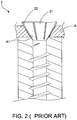
- a further screw 2 mainly provides a plurality of spaced-apart ribs 22 arranged on an underside of a head 21.
- the ribs 22 cut wood fibers and allow the head 21 to enter a wooden workpiece (not shown) . If the screw 2 enter an iron workpiece A with a pre-drilled hole A1 for fastening, the ribs 22 in contact with the iron workpiece A raises the head 21 and forms interstices between the ribs 22 and between the ribs 22 and the iron workpiece A. This situation renders the head 21 unable to fit flush with the hole A1. Thus, the screw 2 still has a poor fastening effect.
- An object of this invention is to provide a screw which reduces the drilling resistance and enhances the fastening stability.
- the screw of this invention is as defined in claim 1 and comprises a head with a central axis, a shank connected to the head, and a plurality of threads spirally disposed on the shank.
- the head includes a top face, a conical underside opposite to the top face, and a plurality of spaced-apart recesses formed on the conical underside.
- the conical underside has two different inclined surfaces, namely a first inclined surface extending downwards from a periphery of the top face and a second inclined surface located between the first inclined surface and the shank.
- the spaced-apart recesses are formed on the first inclined surface, each of which has a recessed area gradually reduced downwards from the periphery of the head.
- Each recess defines a first width adjacent to the top face and a second width adjacent to the second inclined surface.
- the first width is larger than the second width.
- a sum of total recessed areas of the recesses is defined from 30 to 37% of a total surface area of the first inclined surface.
- each thread has from two to six concave surfaces, each of which is curved inward by an angle ranging from 60 to 120 degrees. Any two adjacent concave surfaces meet at a crest.
- the concave surfaces and the crests cut and sever fibers of the workpiece into debris more easily and provide a sufficient space for removal of debris.
- the first inclined surface and the recesses with the gradually reduced recessed area help scrape the debris off and accommodate the debris to prevent the surface of the workpiece from being broken or cracked by the debris subjected to the improper pressing force of the head.
- each recess is reduced from the periphery of the head to a border where the two inclined surfaces meet to form a V shape.
- a first included angle defined between the first inclined surface and the central axis is larger than a second included angle defined between the second inclined surface and the central axis.
- the crests of any two adjacent threads are not aligned with each other.
- the adjacent crests can be aligned with each other.
- a plurality of teeth can be formed on each of the concave surfaces to facilitate the cutting capability.
- a screw 3 of a first preferred embodiment of this invention comprises a head 31 defining a central axis 31a, a shank 32 extending downwards from the head 31, and a plurality of threads 33 spirally disposed around the shank 32.
- the head 31 includes a top face 311, a conical underside 312 opposite to the top face 311, and a plurality of spaced-apart recesses 313 formed on the conical underside 312.
- the conical underside 312 has a first inclined surface 3121 extending downwards from a periphery of the top face 311 and a second inclined surface 3122 disposed between the first inclined surface 3121 and the shank 32.
- the two inclined surfaces 3121, 3122 meets at a border 3123.
- the inclined surfaces 3121, 3122 can be inclined with respect to the central axis 31a of the head 31 by different angles.
- a first included angle 3121a defined between the first inclined surface 3121 and the central axis 31a can be larger than a second included angle 3122a defined between the second inclined surface 3122 and the central axis 31a, thereby presenting different slopes on the conical underside 312.
- the recesses 313 are only formed on the first inclined surface 312.
- Each of the recesses 313 has a recessed area gradually reduced downwards from the periphery of the head 31 and defines a first width W1 adjacent to the top face 311 and a second width W2 adjacent to the second inclined surface 3122.
- the first width W1 is larger than the second width W2 so that the recessed area of the recess 313 can be triangularly contoured to permit a gradual cutting action and facilitate the accommodation of debris.
- each recess 313, reduced from the periphery of the head 31 to the border 3123 to become a V shape is adopted as an example.
- a sum of total recessed areas of the recesses 313 is defined from 30 to 37% of a total surface area of the first inclined surface 3121. In other words, a smooth conical area, as shown in Fig.
- each thread 33 has from two to six concave surfaces 331.
- five concave surfaces 331 are adopted as an example.
- Each of the concave surfaces 331 is curved inward by an angle ranging from 60 to 120 degrees.
- Two adjacent concave surfaces 331 meet at a crest 332.
- the crests 332 of the adjacent threads 33 are connected to form an imaginary line 332a.
- the imaginary line 332a can be parallel to the central axis 31a (shown in Fig.
- each concave surface 331 has a plurality of teeth 333 formed thereon to present a serrated edge, as shown in Fig. 8 .
- the operation of the screw 3 is described with the aid of Fig. 3 , Fig. 5 and Figs. 9 -10.
- the screw 3 is adapted to work with a wooden workpiece 4.
- the threads 33 are rotatably driven to make the shank 32 enter the wooden workpiece 4.
- each thread 33 has multiple crests 332 and concave surfaces 331
- the cooperation of the crests 332 with the concave surfaces 331 helps cut and sever wood fibers of the wooden workpiece 4 into debris to prevent the threads 33 from getting entangled with the fibers.
- the increased resistance is prevented.
- each concave surface 331 and the wooden workpiece 4 is also formed between each concave surface 331 and the wooden workpiece 4 to receive the debris and facilitate the removal of the debris.
- the second inclined surface 3122 can follow the shank 32 quickly because of its smaller included angle 3122a and enter the wooden workpiece 4 easily.
- the wooden workpiece 4 then touches the first inclined surface 3121.
- the smooth conical areas and the triangularly-contoured recesses 313 which are different in height allow the first inclined surface 3121 to pull and scrape off the debris.
- the first inclined surface 3121 with the larger included angle 3121a which forms a gradient different from the gradient of the second inclined surface 3122 also helps pull and scrape the debris off under the rotating force, thereby providing a better cutting and scraping effect.
- the screw 3 is adapted to work with an iron or metal workpiece 5 having a bowl-shaped pre-drilled hole 51.
- the smooth conical areas occupying from 63 to 70% of the total surface area of the first inclined surface 3121 are in close contact with the pre-drilled hole 51 and fit flush therewith.
- the better stability for positioning the screw 3 is attained.
- this invention takes advantages of concave surfaces and crests of each thread to cut wood fibers into debris easily and provide a space for removal of debris.
- the smooth and recessed areas of the first inclined surface of the head further scrape the debris off and receive the debris when the head touches the workpiece.
- This invention can also be adapted to a workpiece with a pre-drilled hole. Thus, a stable fastening effect is obtained.
Landscapes
- Engineering & Computer Science (AREA)
- General Engineering & Computer Science (AREA)
- Mechanical Engineering (AREA)
- Connection Of Plates (AREA)
- Drilling Tools (AREA)
Claims (6)
- Schraube (3) mit einem Kopf (31), der eine mittlere Achse (31a) definiert, wobei ein Schaft (32) von besagtem Kopf (31) nach unten verläuft, und ein Gewinde (33) in einer Spirale um den Schaft (32) angeordnet ist;
der Kopf (31) umfasst eine Oberseite (311), eine konische Unterseite (312) gegenüber der Oberseite (311) und eine Vielzahl von beabstandeten Vertiefungen (313) auf der konischen Unterseite (312), wobei die konische Unterseite (312) eine erste geneigte Oberfläche (3121) umfasst, die von einem Umfang der Oberseite (311) nach unten verläuft, und eine zweite geneigte Oberfläche (3122), die zwischen der ersten geneigten Oberfläche (3121) und dem Schaft (32) verbunden ist, wobei die Vertiefungen (313) auf der ersten geneigten Oberfläche (3121) gebildet sind und jede der Vertiefungen (313) einen vertieften Bereich umfasst, der sich von dem Umfang der Oberseite (311) allmählich nach unten verringert, wobei jede der Vertiefungen (313) eine erste Breite (W1) angrenzend an die Oberseite (311) und eine zweite Breite (W2) angrenzend an die zweite geneigte Oberfläche (3122) definierend, wobei die erste Breite (W1) größer als die zweite Breite (W2) ist,
gekennzeichnet dadurch, dass eine Summe von gesamten vertieften Bereichen der Vertiefungen (313) als 30 bis 37% einer Gesamtfläche der ersten geneigten Oberfläche (3121) definiert wird, wobei ein glatter konischer Bereich zwischen zwei benachbarten vertieften Bereichen (313) gelassen wird, wobei eine Summe von gesamten glatten konischen Bereichen von 63 bis 70% der Gesamtfläche der ersten geneigten Oberfläche (3121) nach Abzug der Summe der gesamten vertieften Bereiche der Gesamtfläche definiert wird, wobei jedes Gewinde (33) zwei bis sechs konkave Oberflächen (331) hat und jede der konkaven Oberflächen (331) in einem Winkel von 60 bis 120 Grad nach innen gebogen ist und jede konkave Oberfläche (331) und jede benachbarte konkave Oberfläche (331) sich an einer Spitze (332) treffen. - Schraube (3) nach Anspruch 1, wobei ein erster Winkel (3121a) zwischen der ersten geneigten Oberfläche (3121) und der mittleren Achse (31a) größer ist als ein zweiter Winkel (3122a) zwischen der zweiten geneigten Oberfläche (3122) und der mittleren Achse (31a).
- Schraube (3) nach Anspruch 1, wobei der vertiefte Bereich von dem Umfang der Oberseite (311) zu einem Rand (3123) hin abnimmt, wo die erste geneigte Oberfläche (3121) und die zweite geneigte Oberfläche (3122) sich treffen.
- Schraube (3) nach einem beliebigen der Ansprüche 1 bis 3, wobei die Spitzen (332) von beliebigen zwei benachbarten Gewinden (33) nicht miteinander ausgerichtet sind.
- Schraube (3) nach einem beliebigen der Ansprüche 1 bis 3, wobei die Spitzen (332) von beliebigen zwei benachbarten Gewinden (33) miteinander ausgerichtet sind.
- Schraube (3) nach einem beliebigen der Ansprüche 1 bis 3, wobei jedes der Gewinde (31) eine Vielzahl von Zähnen (333) hat, die auf jeder der konkaven Oberflächen (331) gebildet sind.
Priority Applications (2)
| Application Number | Priority Date | Filing Date | Title |
|---|---|---|---|
| EP15187653.9A EP3150870B1 (de) | 2015-09-30 | 2015-09-30 | Schraube |
| ES15187653.9T ES2672593T3 (es) | 2015-09-30 | 2015-09-30 | Tornillo |
Applications Claiming Priority (1)
| Application Number | Priority Date | Filing Date | Title |
|---|---|---|---|
| EP15187653.9A EP3150870B1 (de) | 2015-09-30 | 2015-09-30 | Schraube |
Publications (2)
| Publication Number | Publication Date |
|---|---|
| EP3150870A1 EP3150870A1 (de) | 2017-04-05 |
| EP3150870B1 true EP3150870B1 (de) | 2018-04-25 |
Family
ID=54252089
Family Applications (1)
| Application Number | Title | Priority Date | Filing Date |
|---|---|---|---|
| EP15187653.9A Active EP3150870B1 (de) | 2015-09-30 | 2015-09-30 | Schraube |
Country Status (2)
| Country | Link |
|---|---|
| EP (1) | EP3150870B1 (de) |
| ES (1) | ES2672593T3 (de) |
Family Cites Families (2)
| Publication number | Priority date | Publication date | Assignee | Title |
|---|---|---|---|---|
| US5683217A (en) * | 1996-03-27 | 1997-11-04 | Walther; Uli | Self-counter-sinking screw with cutting receiving pockets |
| GB2314133B (en) * | 1996-06-13 | 1998-03-11 | Chao Hsin Yu | Countersunk screws |
-
2015
- 2015-09-30 EP EP15187653.9A patent/EP3150870B1/de active Active
- 2015-09-30 ES ES15187653.9T patent/ES2672593T3/es active Active
Non-Patent Citations (1)
| Title |
|---|
| None * |
Also Published As
| Publication number | Publication date |
|---|---|
| ES2672593T3 (es) | 2018-06-15 |
| EP3150870A1 (de) | 2017-04-05 |
Similar Documents
| Publication | Publication Date | Title |
|---|---|---|
| JP4504366B2 (ja) | 損傷したボルトおよびネジを除去するためのビット | |
| US20140178149A1 (en) | Fastener capable of speedily screwing | |
| US20200056647A1 (en) | Fastener | |
| US10801539B2 (en) | Screw capable of reducing drilling torque | |
| EP3002468A1 (de) | Selbstbohrende Schraube | |
| US20190113066A1 (en) | Wood screw | |
| US20070166124A1 (en) | Screw with ridges and grooves between threads on shank | |
| US7654785B2 (en) | Higher fastening screw | |
| EP1881209A1 (de) | Holzschraube mit Schneidzähnen auf dem Gewinde und mit einem Schaft mit Nuten | |
| EP3916247B1 (de) | Schnelle spanabhebende räumschraube | |
| US20120063865A1 (en) | Screw | |
| CN110792670A (zh) | 锁固件 | |
| EP3150870B1 (de) | Schraube | |
| EP3121462B1 (de) | Schraube | |
| TWI797710B (zh) | 螺絲 | |
| JP2001295818A (ja) | 木ねじ | |
| EP3550160B1 (de) | Befestigungsmittel | |
| TWI592582B (zh) | Expand the aperture screws | |
| US10337548B2 (en) | Crack-proof screw | |
| JP4498857B2 (ja) | ねじ | |
| TWI728013B (zh) | 改良木螺釘 | |
| TWI709694B (zh) | 具切槽之尖尾螺絲 | |
| CN113027890B (zh) | 具切槽的尖尾螺丝 | |
| TWM511559U (zh) | 螺絲 | |
| KR200409655Y1 (ko) | 나사못 |
Legal Events
| Date | Code | Title | Description |
|---|---|---|---|
| PUAI | Public reference made under article 153(3) epc to a published international application that has entered the european phase |
Free format text: ORIGINAL CODE: 0009012 |
|
| AK | Designated contracting states |
Kind code of ref document: A1 Designated state(s): AL AT BE BG CH CY CZ DE DK EE ES FI FR GB GR HR HU IE IS IT LI LT LU LV MC MK MT NL NO PL PT RO RS SE SI SK SM TR |
|
| AX | Request for extension of the european patent |
Extension state: BA ME |
|
| 17P | Request for examination filed |
Effective date: 20170407 |
|
| RBV | Designated contracting states (corrected) |
Designated state(s): AL AT BE BG CH CY CZ DE DK EE ES FI FR GB GR HR HU IE IS IT LI LT LU LV MC MK MT NL NO PL PT RO RS SE SI SK SM TR |
|
| GRAP | Despatch of communication of intention to grant a patent |
Free format text: ORIGINAL CODE: EPIDOSNIGR1 |
|
| INTG | Intention to grant announced |
Effective date: 20170711 |
|
| GRAS | Grant fee paid |
Free format text: ORIGINAL CODE: EPIDOSNIGR3 |
|
| GRAJ | Information related to disapproval of communication of intention to grant by the applicant or resumption of examination proceedings by the epo deleted |
Free format text: ORIGINAL CODE: EPIDOSDIGR1 |
|
| GRAP | Despatch of communication of intention to grant a patent |
Free format text: ORIGINAL CODE: EPIDOSNIGR1 |
|
| INTG | Intention to grant announced |
Effective date: 20171108 |
|
| GRAA | (expected) grant |
Free format text: ORIGINAL CODE: 0009210 |
|
| GRAS | Grant fee paid |
Free format text: ORIGINAL CODE: EPIDOSNIGR3 |
|
| AK | Designated contracting states |
Kind code of ref document: B1 Designated state(s): AL AT BE BG CH CY CZ DE DK EE ES FI FR GB GR HR HU IE IS IT LI LT LU LV MC MK MT NL NO PL PT RO RS SE SI SK SM TR |
|
| REG | Reference to a national code |
Ref country code: GB Ref legal event code: FG4D |
|
| REG | Reference to a national code |
Ref country code: CH Ref legal event code: EP |
|
| REG | Reference to a national code |
Ref country code: AT Ref legal event code: REF Ref document number: 993230 Country of ref document: AT Kind code of ref document: T Effective date: 20180515 |
|
| REG | Reference to a national code |
Ref country code: IE Ref legal event code: FG4D |
|
| REG | Reference to a national code |
Ref country code: DE Ref legal event code: R096 Ref document number: 602015010345 Country of ref document: DE |
|
| REG | Reference to a national code |
Ref country code: ES Ref legal event code: FG2A Ref document number: 2672593 Country of ref document: ES Kind code of ref document: T3 Effective date: 20180615 |
|
| REG | Reference to a national code |
Ref country code: NL Ref legal event code: FP |
|
| REG | Reference to a national code |
Ref country code: LT Ref legal event code: MG4D |
|
| REG | Reference to a national code |
Ref country code: FR Ref legal event code: PLFP Year of fee payment: 4 |
|
| PG25 | Lapsed in a contracting state [announced via postgrant information from national office to epo] |
Ref country code: BG Free format text: LAPSE BECAUSE OF FAILURE TO SUBMIT A TRANSLATION OF THE DESCRIPTION OR TO PAY THE FEE WITHIN THE PRESCRIBED TIME-LIMIT Effective date: 20180725 Ref country code: FI Free format text: LAPSE BECAUSE OF FAILURE TO SUBMIT A TRANSLATION OF THE DESCRIPTION OR TO PAY THE FEE WITHIN THE PRESCRIBED TIME-LIMIT Effective date: 20180425 Ref country code: NO Free format text: LAPSE BECAUSE OF FAILURE TO SUBMIT A TRANSLATION OF THE DESCRIPTION OR TO PAY THE FEE WITHIN THE PRESCRIBED TIME-LIMIT Effective date: 20180725 Ref country code: LT Free format text: LAPSE BECAUSE OF FAILURE TO SUBMIT A TRANSLATION OF THE DESCRIPTION OR TO PAY THE FEE WITHIN THE PRESCRIBED TIME-LIMIT Effective date: 20180425 Ref country code: PL Free format text: LAPSE BECAUSE OF FAILURE TO SUBMIT A TRANSLATION OF THE DESCRIPTION OR TO PAY THE FEE WITHIN THE PRESCRIBED TIME-LIMIT Effective date: 20180425 Ref country code: SE Free format text: LAPSE BECAUSE OF FAILURE TO SUBMIT A TRANSLATION OF THE DESCRIPTION OR TO PAY THE FEE WITHIN THE PRESCRIBED TIME-LIMIT Effective date: 20180425 |
|
| PG25 | Lapsed in a contracting state [announced via postgrant information from national office to epo] |
Ref country code: LV Free format text: LAPSE BECAUSE OF FAILURE TO SUBMIT A TRANSLATION OF THE DESCRIPTION OR TO PAY THE FEE WITHIN THE PRESCRIBED TIME-LIMIT Effective date: 20180425 Ref country code: RS Free format text: LAPSE BECAUSE OF FAILURE TO SUBMIT A TRANSLATION OF THE DESCRIPTION OR TO PAY THE FEE WITHIN THE PRESCRIBED TIME-LIMIT Effective date: 20180425 Ref country code: GR Free format text: LAPSE BECAUSE OF FAILURE TO SUBMIT A TRANSLATION OF THE DESCRIPTION OR TO PAY THE FEE WITHIN THE PRESCRIBED TIME-LIMIT Effective date: 20180726 Ref country code: HR Free format text: LAPSE BECAUSE OF FAILURE TO SUBMIT A TRANSLATION OF THE DESCRIPTION OR TO PAY THE FEE WITHIN THE PRESCRIBED TIME-LIMIT Effective date: 20180425 |
|
| REG | Reference to a national code |
Ref country code: AT Ref legal event code: MK05 Ref document number: 993230 Country of ref document: AT Kind code of ref document: T Effective date: 20180425 |
|
| REG | Reference to a national code |
Ref country code: DE Ref legal event code: R097 Ref document number: 602015010345 Country of ref document: DE |
|
| PG25 | Lapsed in a contracting state [announced via postgrant information from national office to epo] |
Ref country code: EE Free format text: LAPSE BECAUSE OF FAILURE TO SUBMIT A TRANSLATION OF THE DESCRIPTION OR TO PAY THE FEE WITHIN THE PRESCRIBED TIME-LIMIT Effective date: 20180425 Ref country code: DK Free format text: LAPSE BECAUSE OF FAILURE TO SUBMIT A TRANSLATION OF THE DESCRIPTION OR TO PAY THE FEE WITHIN THE PRESCRIBED TIME-LIMIT Effective date: 20180425 Ref country code: AT Free format text: LAPSE BECAUSE OF FAILURE TO SUBMIT A TRANSLATION OF THE DESCRIPTION OR TO PAY THE FEE WITHIN THE PRESCRIBED TIME-LIMIT Effective date: 20180425 Ref country code: SK Free format text: LAPSE BECAUSE OF FAILURE TO SUBMIT A TRANSLATION OF THE DESCRIPTION OR TO PAY THE FEE WITHIN THE PRESCRIBED TIME-LIMIT Effective date: 20180425 Ref country code: CZ Free format text: LAPSE BECAUSE OF FAILURE TO SUBMIT A TRANSLATION OF THE DESCRIPTION OR TO PAY THE FEE WITHIN THE PRESCRIBED TIME-LIMIT Effective date: 20180425 Ref country code: RO Free format text: LAPSE BECAUSE OF FAILURE TO SUBMIT A TRANSLATION OF THE DESCRIPTION OR TO PAY THE FEE WITHIN THE PRESCRIBED TIME-LIMIT Effective date: 20180425 |
|
| PG25 | Lapsed in a contracting state [announced via postgrant information from national office to epo] |
Ref country code: SM Free format text: LAPSE BECAUSE OF FAILURE TO SUBMIT A TRANSLATION OF THE DESCRIPTION OR TO PAY THE FEE WITHIN THE PRESCRIBED TIME-LIMIT Effective date: 20180425 |
|
| PLBE | No opposition filed within time limit |
Free format text: ORIGINAL CODE: 0009261 |
|
| STAA | Information on the status of an ep patent application or granted ep patent |
Free format text: STATUS: NO OPPOSITION FILED WITHIN TIME LIMIT |
|
| 26N | No opposition filed |
Effective date: 20190128 |
|
| PG25 | Lapsed in a contracting state [announced via postgrant information from national office to epo] |
Ref country code: MC Free format text: LAPSE BECAUSE OF FAILURE TO SUBMIT A TRANSLATION OF THE DESCRIPTION OR TO PAY THE FEE WITHIN THE PRESCRIBED TIME-LIMIT Effective date: 20180425 |
|
| REG | Reference to a national code |
Ref country code: CH Ref legal event code: PL |
|
| PG25 | Lapsed in a contracting state [announced via postgrant information from national office to epo] |
Ref country code: SI Free format text: LAPSE BECAUSE OF FAILURE TO SUBMIT A TRANSLATION OF THE DESCRIPTION OR TO PAY THE FEE WITHIN THE PRESCRIBED TIME-LIMIT Effective date: 20180425 |
|
| REG | Reference to a national code |
Ref country code: BE Ref legal event code: MM Effective date: 20180930 |
|
| REG | Reference to a national code |
Ref country code: IE Ref legal event code: MM4A |
|
| PG25 | Lapsed in a contracting state [announced via postgrant information from national office to epo] |
Ref country code: LU Free format text: LAPSE BECAUSE OF NON-PAYMENT OF DUE FEES Effective date: 20180930 |
|
| PG25 | Lapsed in a contracting state [announced via postgrant information from national office to epo] |
Ref country code: IE Free format text: LAPSE BECAUSE OF NON-PAYMENT OF DUE FEES Effective date: 20180930 |
|
| PG25 | Lapsed in a contracting state [announced via postgrant information from national office to epo] |
Ref country code: CH Free format text: LAPSE BECAUSE OF NON-PAYMENT OF DUE FEES Effective date: 20180930 Ref country code: LI Free format text: LAPSE BECAUSE OF NON-PAYMENT OF DUE FEES Effective date: 20180930 Ref country code: BE Free format text: LAPSE BECAUSE OF NON-PAYMENT OF DUE FEES Effective date: 20180930 |
|
| PG25 | Lapsed in a contracting state [announced via postgrant information from national office to epo] |
Ref country code: AL Free format text: LAPSE BECAUSE OF FAILURE TO SUBMIT A TRANSLATION OF THE DESCRIPTION OR TO PAY THE FEE WITHIN THE PRESCRIBED TIME-LIMIT Effective date: 20180425 |
|
| PG25 | Lapsed in a contracting state [announced via postgrant information from national office to epo] |
Ref country code: MT Free format text: LAPSE BECAUSE OF NON-PAYMENT OF DUE FEES Effective date: 20180930 |
|
| PG25 | Lapsed in a contracting state [announced via postgrant information from national office to epo] |
Ref country code: TR Free format text: LAPSE BECAUSE OF FAILURE TO SUBMIT A TRANSLATION OF THE DESCRIPTION OR TO PAY THE FEE WITHIN THE PRESCRIBED TIME-LIMIT Effective date: 20180425 |
|
| PG25 | Lapsed in a contracting state [announced via postgrant information from national office to epo] |
Ref country code: PT Free format text: LAPSE BECAUSE OF FAILURE TO SUBMIT A TRANSLATION OF THE DESCRIPTION OR TO PAY THE FEE WITHIN THE PRESCRIBED TIME-LIMIT Effective date: 20180425 |
|
| PG25 | Lapsed in a contracting state [announced via postgrant information from national office to epo] |
Ref country code: HU Free format text: LAPSE BECAUSE OF FAILURE TO SUBMIT A TRANSLATION OF THE DESCRIPTION OR TO PAY THE FEE WITHIN THE PRESCRIBED TIME-LIMIT; INVALID AB INITIO Effective date: 20150930 Ref country code: CY Free format text: LAPSE BECAUSE OF FAILURE TO SUBMIT A TRANSLATION OF THE DESCRIPTION OR TO PAY THE FEE WITHIN THE PRESCRIBED TIME-LIMIT Effective date: 20180425 Ref country code: MK Free format text: LAPSE BECAUSE OF NON-PAYMENT OF DUE FEES Effective date: 20180425 |
|
| PG25 | Lapsed in a contracting state [announced via postgrant information from national office to epo] |
Ref country code: IS Free format text: LAPSE BECAUSE OF FAILURE TO SUBMIT A TRANSLATION OF THE DESCRIPTION OR TO PAY THE FEE WITHIN THE PRESCRIBED TIME-LIMIT Effective date: 20180825 |
|
| PGFP | Annual fee paid to national office [announced via postgrant information from national office to epo] |
Ref country code: DE Payment date: 20250926 Year of fee payment: 11 |
|
| PGFP | Annual fee paid to national office [announced via postgrant information from national office to epo] |
Ref country code: NL Payment date: 20250925 Year of fee payment: 11 Ref country code: IT Payment date: 20250919 Year of fee payment: 11 |
|
| PGFP | Annual fee paid to national office [announced via postgrant information from national office to epo] |
Ref country code: GB Payment date: 20250923 Year of fee payment: 11 |
|
| PGFP | Annual fee paid to national office [announced via postgrant information from national office to epo] |
Ref country code: FR Payment date: 20250924 Year of fee payment: 11 |
|
| PGFP | Annual fee paid to national office [announced via postgrant information from national office to epo] |
Ref country code: ES Payment date: 20251008 Year of fee payment: 11 |