EP3150170B1 - Multifokale linse und verfahren zu deren herstellung - Google Patents
Multifokale linse und verfahren zu deren herstellung Download PDFInfo
- Publication number
- EP3150170B1 EP3150170B1 EP15188049.9A EP15188049A EP3150170B1 EP 3150170 B1 EP3150170 B1 EP 3150170B1 EP 15188049 A EP15188049 A EP 15188049A EP 3150170 B1 EP3150170 B1 EP 3150170B1
- Authority
- EP
- European Patent Office
- Prior art keywords
- diffractive
- lens
- diffractive structure
- focal point
- structures
- Prior art date
- Legal status (The legal status is an assumption and is not a legal conclusion. Google has not performed a legal analysis and makes no representation as to the accuracy of the status listed.)
- Active
Links
Images




Classifications
-
- A—HUMAN NECESSITIES
- A61—MEDICAL OR VETERINARY SCIENCE; HYGIENE
- A61F—FILTERS IMPLANTABLE INTO BLOOD VESSELS; PROSTHESES; DEVICES PROVIDING PATENCY TO, OR PREVENTING COLLAPSING OF, TUBULAR STRUCTURES OF THE BODY, e.g. STENTS; ORTHOPAEDIC, NURSING OR CONTRACEPTIVE DEVICES; FOMENTATION; TREATMENT OR PROTECTION OF EYES OR EARS; BANDAGES, DRESSINGS OR ABSORBENT PADS; FIRST-AID KITS
- A61F2/00—Filters implantable into blood vessels; Prostheses, i.e. artificial substitutes or replacements for parts of the body; Appliances for connecting them with the body; Devices providing patency to, or preventing collapsing of, tubular structures of the body, e.g. stents
- A61F2/02—Prostheses implantable into the body
- A61F2/14—Eye parts, e.g. lenses or corneal implants; Artificial eyes
- A61F2/16—Intraocular lenses
- A61F2/1613—Intraocular lenses having special lens configurations, e.g. multipart lenses; having particular optical properties, e.g. pseudo-accommodative lenses, lenses having aberration corrections, diffractive lenses, lenses for variably absorbing electromagnetic radiation, lenses having variable focus
- A61F2/1616—Pseudo-accommodative, e.g. multifocal or enabling monovision
- A61F2/1618—Multifocal lenses
-
- A—HUMAN NECESSITIES
- A61—MEDICAL OR VETERINARY SCIENCE; HYGIENE
- A61F—FILTERS IMPLANTABLE INTO BLOOD VESSELS; PROSTHESES; DEVICES PROVIDING PATENCY TO, OR PREVENTING COLLAPSING OF, TUBULAR STRUCTURES OF THE BODY, e.g. STENTS; ORTHOPAEDIC, NURSING OR CONTRACEPTIVE DEVICES; FOMENTATION; TREATMENT OR PROTECTION OF EYES OR EARS; BANDAGES, DRESSINGS OR ABSORBENT PADS; FIRST-AID KITS
- A61F2/00—Filters implantable into blood vessels; Prostheses, i.e. artificial substitutes or replacements for parts of the body; Appliances for connecting them with the body; Devices providing patency to, or preventing collapsing of, tubular structures of the body, e.g. stents
- A61F2/02—Prostheses implantable into the body
- A61F2/14—Eye parts, e.g. lenses or corneal implants; Artificial eyes
- A61F2/16—Intraocular lenses
- A61F2/1613—Intraocular lenses having special lens configurations, e.g. multipart lenses; having particular optical properties, e.g. pseudo-accommodative lenses, lenses having aberration corrections, diffractive lenses, lenses for variably absorbing electromagnetic radiation, lenses having variable focus
- A61F2/1637—Correcting aberrations caused by inhomogeneities; correcting intrinsic aberrations, e.g. of the cornea, of the surface of the natural lens, aspheric, cylindrical, toric lenses
- A61F2/164—Aspheric lenses
-
- A—HUMAN NECESSITIES
- A61—MEDICAL OR VETERINARY SCIENCE; HYGIENE
- A61F—FILTERS IMPLANTABLE INTO BLOOD VESSELS; PROSTHESES; DEVICES PROVIDING PATENCY TO, OR PREVENTING COLLAPSING OF, TUBULAR STRUCTURES OF THE BODY, e.g. STENTS; ORTHOPAEDIC, NURSING OR CONTRACEPTIVE DEVICES; FOMENTATION; TREATMENT OR PROTECTION OF EYES OR EARS; BANDAGES, DRESSINGS OR ABSORBENT PADS; FIRST-AID KITS
- A61F2/00—Filters implantable into blood vessels; Prostheses, i.e. artificial substitutes or replacements for parts of the body; Appliances for connecting them with the body; Devices providing patency to, or preventing collapsing of, tubular structures of the body, e.g. stents
- A61F2/02—Prostheses implantable into the body
- A61F2/14—Eye parts, e.g. lenses or corneal implants; Artificial eyes
- A61F2/16—Intraocular lenses
- A61F2/1613—Intraocular lenses having special lens configurations, e.g. multipart lenses; having particular optical properties, e.g. pseudo-accommodative lenses, lenses having aberration corrections, diffractive lenses, lenses for variably absorbing electromagnetic radiation, lenses having variable focus
- A61F2/1654—Diffractive lenses
- A61F2/1656—Fresnel lenses, prisms or plates
-
- G—PHYSICS
- G02—OPTICS
- G02C—SPECTACLES; SUNGLASSES OR GOGGLES INSOFAR AS THEY HAVE THE SAME FEATURES AS SPECTACLES; CONTACT LENSES
- G02C7/00—Optical parts
- G02C7/02—Lenses; Lens systems ; Methods of designing lenses
- G02C7/04—Contact lenses for the eyes
- G02C7/041—Contact lenses for the eyes bifocal; multifocal
- G02C7/044—Annular configuration, e.g. pupil tuned
-
- G—PHYSICS
- G02—OPTICS
- G02C—SPECTACLES; SUNGLASSES OR GOGGLES INSOFAR AS THEY HAVE THE SAME FEATURES AS SPECTACLES; CONTACT LENSES
- G02C2202/00—Generic optical aspects applicable to one or more of the subgroups of G02C7/00
- G02C2202/20—Diffractive and Fresnel lenses or lens portions
Definitions
- the present invention relates to a multifocal intraocular or contact lens, having a refractive focus and a first and a second diffractive structure, which at least partially overlap.
- the invention relates to a method for producing such a multifocal lens.
- Multifocal intraocular or contact lenses i.
- Lenses with multiple focal points e.g. can be used for near and far vision (bifocal) or near, intermediate and far-sighted (trifocal), have been known for several decades and use a variety of diffractive structures on a refractive base lens to create in addition to the refractive focus one or more diffractive foci ,
- the objective is achieved with a lens of the initially mentioned type, in which the two diffractive structures are different, and wherein a first-order focus of the first diffractive structure coincides with a first-order focus of the second diffractive structure.
- the calculation of the superimposed diffractive structure can be considerably simplified, since the structures to be superimposed each have a profile with the same period lengths. Adjustments of the structures for determining an optimal intensity distribution during the calculation can thus be carried out particularly easily.
- the two diffractive structures have different intensity distributions, whereby an individual mixture of intensity ratios is possible.
- a particularly advantageous embodiment of the invention is characterized in that the first diffractive structure has an intensity distribution asymmetric about the refractive focus and the second diffractive structure has an intensity distribution substantially symmetrical about the refractive focus.
- diffractive foci of "positive” order are defined below as being between the lens and its refractive focus and "negative” order diffractive foci as those located on the side of the refractive focus away from the lens.
- the focal point of the first positive order of the diffractive structures corresponds to a distance for the intermediate view and the focal point of the second positive order of the diffractive structures to a distance for near vision.
- the respective negative focal points of the diffractive structures are in this case imaged behind the retina of the user of the lens, which is why they are not usable by the user and contribute to a deterioration of the image quality.
- intensity components of the (originally) negative orders are mapped to the positive orders used or to the zeroth (refractive) order, which results in comparison to the prior art a more colorful and high-contrast Picture shows, since the usable focal points have higher intensity components.
- the refractive focus is used for near vision
- the focal point of the first negative order of the overlay structure corresponds to a distance for the intermediate view
- the focal point of the second negative order of the overlay structure corresponds to a distance for the distance view.
- the positive orders of the diffractive structures are poorly utilizable since they are located in front of the near-vision focal point
- the orders of the third negative order are not usable because they are focused only behind the retina.
- the intensity components of the positive orders are mapped to the zeroth (refractive), negative first and negative second order, resulting in a higher light yield in the usable focal points and thus a more intense and high-contrast image compared to the prior art.
- the profiles of the two diffractive structures have an equal period length, wherein the profile of the first diffractive structure is monotonically increasing within the period and the profile of the second diffractive structure has a minimum in the first half of the period and a maximum in the second half of the period ,
- Such tips are difficult to manufacture and lead to inaccurate manufacturing errors in the image area, which gives the viewer a blurred or cloudy picture.
- the first diffractive structure ie the structure with the asymmetrical intensity distribution
- the second diffractive structure ie the structure with the essentially symmetrical intensity distribution
- This profile profiles can be used, their behavior is well known and also allow easy production.
- At least one of the profiles may have rounded or chamfered flanks.
- the two diffractive structures overlap only in a central region of the lens.
- the lens outside the central area may not have any diffractive structure at all. If the pupil becomes larger, for example with low incidence of light, then the influence of the non-central region or the refractive component for the distance vision increases, so that with such pupil sizes the intensity distribution only encompasses distance vision.
- the lens may also have only one of the two diffractive structures outside the central region, as a result of which, for example, the near and far vision or the intermediate and long-distance vision can be designed to be the largest for wide pupils.
- the two diffractive structures are preferably apodized in the radial direction of the lens, preferably with different strengths. This ensures that with a small pupil a different intensity distribution results than with a large pupil. In addition, there is a constant transition of the change in the intensity distribution in widening or shrinking pupils. If the apodizations are chosen to be different degrees, the intensity distributions can be adjusted as desired to the desired pupil size.
- the lens of the invention can basically be used in any optical devices, but is particularly suitable as a multifocal contact or intraocular lens.
- the step of incorporating the overlay structure in the lens blank is preferably carried out by rotation, which allows a particularly precise production of the multifocal lens.
- a mold blank having the overlay structure i. a "negative mold” created, e.g. by turning or milling.
- the lens can be cast, pressed, tested or otherwise shaped by means of the negative mold.
- the contacting preferably takes place by casting the lens material on the mold blank and curing the lens material.
- the lens material can in this case solidify by itself or be cured by means of light or heat treatment.
- Both embodiments of the method according to the invention are characterized by a simple calculation of the superposed structure, in that two structures, e.g. superimposed by simple addition, which requires low processing power.
- the first diffractive structure has an intensity distribution which is asymmetrical about the refractive focus
- the second diffractive structure has an intensity distribution substantially symmetrical about the refractive focus
- the Fig. 1 and 2 show a lens 1 with a front 2, a back 3 and an optical axis 4.
- the lens 1 has a central zone Z 1 and two annular zones Z 2 , Z 3 , which will be explained later in more detail.
- the described lens 1 is used as an intraocular lens or contact lens, but can also be used in optical devices.
- the lens 1 has a refractive focus F r lying on the optical axis 4, which can be used for the distance or near vision as described below and is also referred to below as the zero-order focal point.
- F r refractive focus
- 3 of the lens 1 is a diffractive Structure 5 incorporated, see Fig. 4 to adapt the lens 1 for both near and intermediate and distance vision.
- the diffractive foci F g, 1 , F g, 2 are referred to as foci of positive first and second order of the diffractive structure 5 and lie on the optical axis 4 between the lens 1 and the refractive focus F r .
- the diffractive foci F g, -1 , F g, -2 are referred to as foci of negative first and second order of the diffractive structure 5 and lie on the side facing away from the lens 1 of the refractive focus F r .
- the intensity distribution attributed to the respective focal points F g, i should not be symmetrical.
- the diffractive structure 5 as follows from a first and a second diffractive structure 6, 7, which overlap in at least one of the zones Z 1 , Z 2 , Z 3 .
- Fig. 3 shows in the upper diagram the profile 11 of the first diffractive structure 6 (abscissa: radius r 2 [mm 2 ]; ordinate: tread depth T [mm]).
- the first diffractive structure 6 has a grating period p 1 (r) which depends on the radius r, more precisely r 2 . If the structure 6 is plotted as abscissa scale via r 2 , the period p 1 occurs in equidistant repetitions over the abscissa.
- the first diffractive structure 6 has an asymmetrical intensity distribution around the refractive focus F r in its diffractive focal points F 1, i , see later Fig. 5 , And has for this purpose a profile 8 with, applied over the squared radius r 2 , asymmetrically on and descending flanks 9, 10, wherein one of the flanks 9, 10 may be perpendicular.
- Fig. 3 shows the first diffractive structure 6 with a sawtooth shape, but alternatively it could also have an echelette or kinoform.
- the grating period p 1 (r) determines the distance of the foci F 1, i generated by the first diffractive structure 6 from the refractive focus F r .
- Fig. 3 shows in the middle diagram the profile of the second diffractive structure 7 (abscissa: radius r 2 [mm 2 ]; ordinate: profile depth T [mm]).
- the second diffractive structure 7 has a grating period p 2 (r) which depends on the radius r, more precisely r 2 . If the structure 7 is plotted as abscissa scale via r 2 , the period p 2 occurs in equidistant repetitions over the abscissa.
- the second diffractive structure 7 has a substantially symmetrical intensity distribution around the refractive focus F r in their diffractive foci F 2, i , as later with reference to Fig. 5 explained in more detail.
- the structure 7 has a profile with respect to one another, plotted over the square radius r 2 , and essentially flanking and descending flanks 12, 13, which are preferably perpendicular.
- the term "substantially symmetrical" in each case includes slight deviations from the symmetry.
- Fig. 3 shows the second diffractive structure 7 as a binary structure, ie with a rectangular shape. Alternatively, however, it could also have, for example, a trapezoidal or sinusoidal shape.
- the grating period p 2 (r) determines the distance of the foci F 2, i generated by the second diffractive structure 7 from the refractive focus F r .
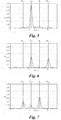
- Fig. 5 shows the intensity distribution of a lens, to which only a first diffractive structure 6 according to the top diagram of Fig. 3 is plotted (abscissa: distance D from the lens [mm]; ordinate: relative intensity I [1]). As shown, the intensity distribution of the diffractive foci F 1, i is asymmetric about the refractive focus.
- Fig. 6 shows the intensity distribution of a lens 1, to which only a second diffractive structure 7 according to the middle diagram of Fig. 3 is plotted (abscissa: distance D from the lens [mm]; ordinate: relative intensity I [1]).
- the foci F 2,1 , F 2,2 , ... of positive order have a substantially equal intensity component as the foci F 2, -1 , F 2, -2 , ... of negative order.
- the grating periods p 1 (r) and p 2 (r) are shown to be the same, so that according to FIGS FIGS. 5 and 6 the first positive focus F 1,1 of the first diffractive structure 6 is located at a distance from the refractive focus F r which corresponds to the distance of the first positive focus F 2,1 of the second diffractive structure 7.
- the composite, "superimposed" diffractive structure 5 is obtained by additive superposition of the two structures 6, 7 (abscissa: radius r 2 [mm 2 ]; ordinate: profile depth T [mm]).
- the superimposed diffractive structure 5 has a profile 14 with rising and falling edges 15, 16, so that the profile 14 of the diffractive structure 5 is monotonically increasing substantially within one period.
- the diffractive structure 5 with the profile 14 is applied to one of the sides 2, 3 of the lens 1, see Fig. 4 ,
- the profiles 8, 11, 14 may have rounded or chamfered flanks 9, 10, 12, 13, 15, 16.
- the profile 8 of the first diffractive structure 6 is monotonically increasing within the period p 1 (r) and the profile 11 of the second diffractive structure 7 has a minimum in the first half of the period p 2 (r) and in the second half of the second Period a maximum.
- the profile 14 of the superimposed diffractive structure 5 is monotonously increasing within the period p 1 (r), p 2 (r) and thus has only a maximum within this period.
- the second diffractive structure 7 may be the maximum also in the first half of the period p 2 (r) and the minimum in the second half of the period, which then leads to a superimposed diffractive structure 5 with two maxima per period. For manufacturing reasons, the first-mentioned variant with only one maximum per period is to be preferred.
- Fig. 7 shows the intensity distribution of the lens 1, in which the diffractive structure 5 from the added or superimposed structures 6, 7 is incorporated (abscissa: distance D from the lens [mm]; ordinate: relative intensity I [1]).
- the refractive focus F r is used here for the distance vision
- the first positive diffractive focus F g, 1 corresponds in position to the focal points F 1,1 , F 2,1 first (positive) order of the diffractive structures 6, 7 and is for the intermediate view uses
- the second positive diffractive focus F g, 2 corresponds in position to the focal points F 1,2 , F 2,2 second (positive) order of the diffractive structures 6, 7 and is used for near vision.
- the slopes of the flanks 9, 10, 12, 13 could each be reversed, whereby then, for example, the refractive focus F r for the near vision and the diffractive foci F 1 , F 2.1 and second order F 1, 2 , F 2,2 could be used for the intermediary or far vision.
- the two structures 6, 7 can each be applied either to the entire surface of the side 2, 3 of the lens 1 or only zonal, as in Fig. 1 shown.
- the combined structure 5 can be applied only in the innermost zone Z 1 , ie in the central region, of the lens 1.
- Only one of the two structures 6, 7 can be applied to a surrounding annular zone Z 2 , and none of the structures 5, 6, 7 can be applied in an outermost annular zone Z 3.
- an intensity distribution dependent on the pupil size is achieved, the weighting of the intensity at the refractive focus F r increases with increasing pupil size.
- this effect can be achieved by apodization of the structures 5, 6, 7. This means that the depth T of the profiles 8, 11, 14 of the structures 5, 6, 7 decreases with increasing lens radius r (not in FIG Fig. 3 shown).
- the 8 and 9 show two variants of the method for producing the multifocal lens 1.
- the diffractive structure 5 also called “superposition structure” 5
- the structures 6, 7 can be made available to the arithmetic unit 17 by means of memories 18, 19 or calculated or determined in the arithmetic unit 17 itself.
- Fig. 8 shows a first variant of the manufacturing method, in which the overlay structure 5 calculated in the arithmetic unit 17 is incorporated into a lens blank 20, for example by a machining such as turning in a lathe 21 so as to produce the multifocal lens 1.
- the lens blank 20 is rotated about its optical axis and the rotary tool of the lathe 21 operates during the rotation of the lens blank 20, the overlay structure 5 in the lens blank 20 a.
- the lens 1 can optionally be polished.
- the lens blank 20 could also be merely a processable starting material for a 3D printer, and the incorporation of the overlay structure 5 in the lens blank 5 is then carried out by 3D printing the starting material 20 to the multifocal lens 1.
- Fig. 9 shows a second variant of the manufacturing process, in which the calculated in the arithmetic unit overlay structure 5 is first incorporated as a negative in a mold blank 22, for example, again by means of a lathe 21 or a 3D printer. Subsequently, a lens material 20 is brought into contact with the mold blank 22 so as to produce the multifocal lens 1.
- the lens material 20 may for example already be prefabricated to a lens blank in which the overlay structure 5 is pressed or embossed by means of the mold blank 22 as a "punch".
- the lens material 20 may be in a liquid or viscous state and may be cast onto the mold blank, eg in a mold. Subsequently, the lens material 20 is cured, for example by means of light or heat.
- Fig. 10 shows a comparison of the intensity profile 23 of the lens 1 presented here with the intensity curve 24 of a lens according to the prior art (abscissa: distance D from the lens [mm]; Ordinate: relative intensity I [1]).
- the prior art comparative lens is provided with a structure in which two diffractive structures having asymmetrical intensity distributions (eg, sawtooth-shaped structures) are superimposed, with the first order focal point of the first diffractive structure coinciding with the second order focal point of the second diffractive structure.
Landscapes
- Health & Medical Sciences (AREA)
- Ophthalmology & Optometry (AREA)
- General Health & Medical Sciences (AREA)
- Public Health (AREA)
- Vascular Medicine (AREA)
- Veterinary Medicine (AREA)
- Cardiology (AREA)
- Oral & Maxillofacial Surgery (AREA)
- Transplantation (AREA)
- Engineering & Computer Science (AREA)
- Biomedical Technology (AREA)
- Heart & Thoracic Surgery (AREA)
- Animal Behavior & Ethology (AREA)
- Life Sciences & Earth Sciences (AREA)
- Physics & Mathematics (AREA)
- General Physics & Mathematics (AREA)
- Optics & Photonics (AREA)
- Prostheses (AREA)
- Eyeglasses (AREA)
- Diffracting Gratings Or Hologram Optical Elements (AREA)
Description
- Die vorliegende Erfindung betrifft eine multifokale Intraokular- oder Kontaktlinse, mit einem refraktiven Brennpunkt und einer ersten und einer zweiten diffraktiven Struktur, die sich zumindest teilweise überlagern. In einem weiteren Aspekt betrifft die Erfindung ein Verfahren zur Herstellung einer solchen multifokalen Linse.
- Multifokale Intraokular- oder Kontaktlinsen, d.h. Linsen mit mehreren Brennpunkten, die z.B. für Nah- und Fernsicht (bifokal) oder Nah-, Intermediär- und Fernsicht (trifokal) verwendet werden können, sind seit mehreren Jahrzehnten bekannt und verwenden verschiedenste diffraktive Strukturen auf einer refraktiven Basislinse, um zusätzlich zum refraktiven Brennpunkt einen oder mehrere diffraktive Brennpunkte zu schaffen.
- Gemäß den Schriften
DE 20 2009 018 881 U1 undEP 2 503 962 B1 werden dazu zwei diffraktive Strukturen mit jeweils Kinoformprofil überlagert. Die eine der beiden diffraktiven Strukturen hat hier einen Brennpunkt erster Ordnung, der mit dem Brennpunkt zweiter Ordnung der anderen Struktur zusammenfällt. Die Anmelderin hat erkannt, dass die Berechnung solcher Strukturen äußerst kompliziert ist. Zudem führt eine Einarbeitung solcher Strukturen in die Linse zu einer Vielzahl schwierig zu fertigender Profilspitzen, was wiederum zu einer suboptimalen Verteilung bzw. Lichtausbeute der Lichtintensitäten in den erzeugten Brennpunkten führt. Aus dem DokumentUS-A-2011/0267693 ist eine multifokale Intraokular- oder Kontaktlinse gemäß dem Oberbegriff des Anspruchs 1 bekannt. Die Erfindung setzt sich zum Ziel, eine verbesserte Linse zu schaffen, die die Nachteile des Standes der Technik überwindet. - Gemäß einem ersten Aspekt der Erfindung wird das Ziel mit einer Linse der einleitend genannten Art erreicht, bei welcher die beiden diffraktiven Strukturen unterschiedlich sind, und wobei ein Brennpunkt erster Ordnung der ersten diffraktiven Struktur mit einem Brennpunkt erster Ordnung der zweiten diffraktiven Struktur zusammenfällt.
- Durch die Überlagerung zweier diffraktiver Strukturen, deren Brennpunkte erster Ordnung zusammenfallen, kann die Berechnung der überlagerten diffraktiven Struktur erheblich vereinfacht werden, da die zu überlagernden Strukturen jeweils ein Profil mit gleichen Periodenlängen haben. Adjustierungen der Strukturen zur Ermittlung einer optimalen Intensitätsverteilung während der Berechnung können somit besonders einfach durchgeführt werden.
- Bevorzugt haben die beiden diffraktiven Strukturen unterschiedliche Intensitätsverteilungen, wodurch eine individuelle Mischung von Intensitätsverhältnissen möglich ist.
- Eine besonders vorteilhafte Ausführungsform der Erfindung zeichnet sich dadurch aus, dass die erste diffraktive Struktur eine um den refraktiven Brennpunkt asymmetrische Intensitätsverteilung und die zweite diffraktive Struktur eine um den refraktiven Brennpunkt im Wesentlichen symmetrische Intensitätsverteilung hat.
- Durch die Überlagerung dieser beiden diffraktiven Strukturen wird eine Linse geschaffen, deren für Nah-, Intermediär- und Fernsicht nutzbare Brennpunkte einen höheren Intensitätsanteil aufweisen als im Stand der Technik bekannt. Zur genaueren Betrachtung des Problems werden im Folgenden diffraktive Brennpunkte "positiver" Ordnung als diejenigen definiert, die zwischen der Linse und ihrem refraktiven Brennpunkt liegen, und diffraktive Brennpunkte "negativer" Ordnung als diejenigen, die auf der der Linse abgewandten Seite des refraktiven Brennpunkts liegen.
- Wenn beispielsweise der refraktive Brennpunkt für die Fernsicht eingesetzt wird, entspricht der Brennpunkt erster positiver Ordnung der diffraktiven Strukturen einem Abstand für die Intermediärsicht und der Brennpunkt zweiter positiver Ordnung der diffraktiven Strukturen einem Abstand für die Nahsicht. Die jeweiligen negativen Brennpunkte der diffraktiven Strukturen werden in diesem Fall erst hinter der Netzhaut des Benutzers der Linse abgebildet, weshalb diese für den Benutzer nicht nutzbar sind und zu einer Verschlechterung der Bildqualität beitragen.
- Durch die erfindungsgemäße Überlagerung einer diffraktiven Struktur mit symmetrischer Intensitätsverteilung mit einer diffraktiven Struktur mit asymmetrischer Intensitätsverteilung werden hingegen Intensitätsanteile der (ursprünglich) negativen Ordnungen auf die genutzten positiven Ordnungen bzw. auf die nullte (refraktive) Ordnung abgebildet, wodurch sich im Vergleich zum Stand der Technik ein farbintensiveres und kontrastreicheres Bild ergibt, da die nutzbaren Brennpunkte höhere Intensitätsanteile aufweisen.
- Dieselben Vorteile ergeben sich, wenn beispielsweise in einer alternativen Ausführungsform der refraktive Brennpunkt für die Nahsicht eingesetzt wird, und der Brennpunkt erster negativer Ordnung der Überlagerungsstruktur einem Abstand für die Intermediärsicht und der Brennpunkt zweiter negativer Ordnung der Überlagerungsstruktur einem Abstand für die Fernsicht entspricht. In dieser Ausführungsform sind die positiven Ordnungen der diffraktiven Strukturen schlecht nutzbar, da sie vor dem Nahsicht-Brennpunkt liegen, und die Ordnungen dritter negativer Ordnung gar nicht nutzbar, da sie erst hinter der Netzhaut fokussiert werden. Gemäß der Erfindung werden hier die Intensitätsanteile der positiven Ordnungen auf die nullte (refraktive), negative erste und negative zweite Ordnung abgebildet, wodurch sich im Vergleich zum Stand der Technik wieder eine höhere Lichtausbeute in den nutzbaren Brennpunkten und damit ein farbintensiveres und kontrastreicheres Bild ergibt.
- Bevorzugt haben die Profile der beiden diffraktiven Strukturen eine gleiche Periodenlänge, wobei das Profil der ersten diffraktiven Struktur innerhalb der Periode monoton steigend ist und das Profil der zweiten diffraktiven Struktur in der ersten Hälfte der Periode ein Minimum und in der zweiten Hälfte der Periode ein Maximum hat. Dadurch wird erreicht, dass das resultierende Profil der Linse eine geringe Anzahl an Profilspitzen aufweist. Derartige Spitzen sind schwierig zu fertigen und führen bei einer ungenauen Fertigung zu Fehlern im Bildbereich, wodurch sich dem Betrachter ein unscharfes bzw. trübes Bild ergibt. Beispielsweise hat die erste diffraktive Struktur, d.h. die Struktur mit der asymmetrischen Intensitätsverteilung, ein Profil mit Sägezahn-, Echelette- oder Kinoform, und die zweite diffraktive Struktur, d.h. die Struktur mit der im Wesentlichen symmetrischen Intensitätsverteilung, ein Profil mit Rechteck-, Trapez- oder Sinusform. Dadurch können Profilverläufe eingesetzt werden, deren Verhalten gut bekannt ist und die zudem eine leichte Fertigung erlauben.
- Gemäß einem bevorzugten Merkmal der Erfindung kann zumindest eines der Profile abgerundete oder abgefaste Flanken haben. Dadurch können Fertigungsprozesse mit geringeren Toleranzen gewählt werden, was sowohl Herstellungskosten als auch Herstellungszeit minimiert.
- In einer weiteren vorteilhaften Ausführungsform der Erfindung überlagern sich die beiden diffraktiven Strukturen nur in einem zentralen Bereich der Linse. Beispielsweise kann die Linse außerhalb des zentralen Bereichs überhaupt keine diffraktive Struktur aufweisen. Wird die Pupille größer, z.B. bei geringem Lichteinfall, so wird der Einfluss des nicht-zentralen Bereichs bzw. des refraktiven Anteils für die Fernsicht größer, so dass bei solchen Pupillengrößen die Intensitätsverteilung lediglich die Fernsicht umfasst. Alternativ kann die Linse außerhalb des zentralen Bereichs auch nur eine der beiden diffraktiven Strukturen aufweisen, wodurch z.B. die Nah- und Fernsicht oder die Intermediär- und Fernsicht bei weiten Pupillen am größten gestaltet werden kann.
- Bevorzugt sind die beiden diffraktiven Strukturen in radialer Richtung der Linse apodisiert, bevorzugt unterschiedlich stark. Dadurch wird erreicht, dass sich bei einer kleinen Pupille eine andere Intensitätsverteilung ergibt als bei einer großen Pupille. Zudem ergibt sich ein stetiger Übergang der Änderung der Intensitätsverteilung bei aufweitenden bzw. verkleinernden Pupillen. Werden die Apodisierungen unterschiedlich stark gewählt, können die Intensitätsverteilungen nach Belieben an die gewünschte Pupillengröße angepasst werden.
- Die Linse der Erfindung kann grundsätzlich in beliebigen optischen Geräten eingesetzt werden, besonders eignet sie sich jedoch als multifokale Kontakt- oder Intraokularlinse.
- Gemäß einem zweiten Aspekt schafft die Erfindung auch ein Verfahren zur Herstellung der hier vorgestellten Linse. In einer ersten Ausführungsform umfasst das Verfahren die folgenden Schritte:
- a) Bereitstellen eines Linsenrohlings mit einem refraktiven Brennpunkt;
- b) Berechnen einer Überlagerungsstruktur aus einer ersten diffraktiven Struktur und einer zweiten diffraktiven Struktur, wobei die beiden diffraktiven Strukturen unterschiedlich sind und wobei ein Brennpunkt erster Ordnung der ersten diffraktiven Struktur mit einem Brennpunkt erster Ordnung der zweiten diffraktiven Struktur zusammenfällt; und
- c) Einarbeiten der Überlagerungsstruktur in den Linsenrohling zum Herstellen der multifokalen Linse.
- Der Schritt des Einarbeitens der Überlagerungsstruktur in den Linsenrohling erfolgt bevorzugt durch Drehen, was eine besonders präzise Fertigung der multifokalen Linse erlaubt.
- In einer zweiten Ausführungsform umfasst das Verfahren die folgenden Schritte:
- a) Bereitstellen eines Formrohlings;
- b) Berechnen einer Überlagerungsstruktur aus einer ersten diffraktiven Struktur und einer zweiten diffraktiven Struktur, wobei die beiden diffraktiven Strukturen unterschiedlich sind und wobei ein Brennpunkt erster Ordnung der ersten diffraktiven Struktur mit einem Brennpunkt erster Ordnung der zweiten diffraktiven Struktur zusammenfällt;
- c) Einarbeiten der Überlagerungsstruktur als Negativ in den Formrohling; und
- d) Herstellen der multifokalen Linse durch Inkontaktbringen eines Linsenmaterials mit dem Formrohling, wobei dem Linsenmaterial auch ein refraktiver Brennpunkt verliehen wird.
- Bei dieser Ausführungsform wird zuerst ein Formrohling mit der Überlagerungsstruktur, d.h. eine "Negativform", geschaffen, z.B. durch Drehen oder Fräsen. Danach kann die Linse mittels der Negativform gegossen, gepresst, geprüft oder sonstwie geformt werden.
- Bevorzugt erfolgt das Inkontaktbringen durch Gießen des Linsenmaterials auf den Formrohling und Aushärten des Linsenmaterials. Das Linsenmaterial kann hierbei von selbst erstarren oder z.B. mittels Lichts oder Wärmebehandlung ausgehärtet werden.
- Beide Ausführungsformen des erfindungsgemäßen Verfahrens zeichnen sich durch eine einfache Berechnung der Überlagerungsstruktur aus, indem zwei Strukturen z.B. durch einfache Addition überlagert werden, was geringe Rechenleistung benötigt.
- Insbesondere bevorzugt hat bei beiden Ausführungsformen die erste diffraktive Struktur eine um den refraktiven Brennpunkt asymmetrische Intensitätsverteilung und die zweite diffraktive Struktur eine um den refraktiven Brennpunkt im Wesentlichen symmetrische Intensitätsverteilung.
- Bezüglich weiterer Merkmale und Vorteile des erfindungsgemäßen Verfahrens zur Herstellung der multifokalen Linse wird auf die vorgenannten Merkmale und Vorteile der erfindungsgemäßen Linse verwiesen.
- Die Erfindung wird nachfolgend anhand von in den beigeschlossenen Zeichnungen dargestellten Ausführungsbeispielen näher erläutert. In den Zeichnungen zeigen:
-
Fig. 1 die erfindungsgemäße Linse in einer schematischen Draufsicht; -
Fig. 2 die Linse vonFig. 1 in einer schematischen Seitenansicht; -
Fig. 3 Profile einer ersten und einer zweiten diffraktiven Struktur sowie das Profil einer sich aus der Überlagerung der ersten und zweiten Strukturen ergebenden Überlagerungsstruktur für die Linse vonFig. 1 ; -
Fig. 4 die Linse vonFig. 1 mit der Überlagerungsstruktur vonFig. 3 in einem vergrößerten Halbschnitt; -
Fig. 5 die Intensitätsverteilung einer mit der ersten diffraktiven Struktur vonFig. 3 ausgestatteten Linse; -
Fig. 6 die Intensitätsverteilung einer mit der zweiten diffraktiven Struktur vonFig. 3 ausgestatteten Linse; -
Fig. 7 die Intensitätsverteilung der erfindungsgemäßen Linse vonFig. 1 ; -
Fig. 8 eine erste Ausführungsform des erfindungsgemäßen Verfahrens zur Herstellung der Linse vonFig. 1 in einem schematischen Blockdiagramm; -
Fig. 9 eine zweite Ausführungsform des erfindungsgemäßen Verfahrens zur Herstellung der Linse vonFig. 1 in einem schematischen Blockdiagramm; und -
Fig. 10 einen Vergleich der Intensitätsverteilung der erfindungsgemäßen Linse mit einer Linse nach dem Stand der Technik. - Die
Fig. 1 und 2 zeigen eine Linse 1 mit einer Vorderseite 2, einer Rückseite 3 und einer optischen Achse 4. Die Linse 1 hat eine zentrale Zone Z1 und zwei annulare Zonen Z2, Z3, die später noch näher erläutert werden. Die beschriebene Linse 1 wird als Intraokularlinse oder Kontaktlinse eingesetzt, kann aber auch in optischen Geräten verwendet werden. - Die Linse 1 hat einen auf der optischen Achse 4 liegenden refraktiven Brennpunkt Fr, der wie unten beschrieben für die Fern- oder Nahsicht eingesetzt werden kann und im Folgenden auch als Brennpunkt nullter Ordnung bezeichnet wird. In die Rück- oder Vorderseite 2, 3 der Linse 1 ist eine diffraktive Struktur 5 eingearbeitet, siehe
Fig. 4 , um die Linse 1 sowohl für Nah- als auch Intermediär- und Fernsicht zu adaptieren. - Die diffraktive Struktur 5 erzeugt eine Vielzahl von auf der optischen Achse 4 liegenden weiteren Brennpunkten Fg,i, i = ..., -2, -1, 1, 2, ..., die im Wesentlichen symmetrisch um den refraktiven Brennpunkt Fr verteilt sind, wobei der refraktive Brennpunkt Fr durch die Form der Linse 1 unabhängig von der aufgetragenen diffraktiven Struktur 5 gegeben ist. Die diffraktiven Brennpunkte Fg,1, Fg,2 werden als Brennpunkte positiver erster bzw. zweiter Ordnung der diffraktiven Struktur 5 bezeichnet und liegen auf der optischen Achse 4 zwischen der Linse 1 und dem refraktiven Brennpunkt Fr. Die diffraktiven Brennpunkte Fg,-1, Fg,-2 werden als Brennpunkte negativer erster bzw. zweiter Ordnung der diffraktiven Struktur 5 bezeichnet und liegen auf der der Linse 1 abgewandten Seite des refraktiven Brennpunkts Fr.
- Obwohl die (Positions-)Verteilung der Brennpunkte Fg,i im Wesentlichen symmetrisch um den refraktiven Brennpunkt Fr ist, soll die Intensitätsverteilung, die den jeweiligen Brennpunkten Fg,i zukommt, nicht symmetrisch sein. So sollen sich bei einer trifokalen Linse insbesondere drei größte Intensitäten ausbilden, nämlich für die Fern-, Intermediär- und Nahsicht. Dies wird erreicht, indem die diffraktive Struktur 5 wie folgt aus einer ersten und einer zweiten diffraktiven Struktur 6, 7 gebildet wird, die sich in zumindest einer der Zonen Z1, Z2, Z3 überlagern.
-
Fig. 3 zeigt in dem oberen Diagramm das Profil 11 der ersten diffraktiven Struktur 6 (Abszisse: Radius r2 [mm2]; Ordinate: Profiltiefe T [mm]). Die erste diffraktive Struktur 6 hat eine Gitterperiode p1(r), die vom Radius r abhängig ist, genauer von r2. Wird die Struktur 6 über r2 als Abszissenmaßstab aufgetragen, tritt die Periode p1 in äquidistanten Wiederholungen über der Abszisse auf. - Die erste diffraktive Struktur 6 hat eine um den refraktiven Brennpunkt Fr asymmetrische Intensitätsverteilung in ihren diffraktiven Brennpunkten F1,i, siehe dazu später
Fig. 5 , und weist dazu ein Profil 8 mit, aufgetragen über dem quadrierten Radius r2, asymmetrisch an- und absteigenden Flanken 9, 10 auf, wobei eine der Flanken 9, 10 senkrecht sein kann. -
Fig. 3 zeigt die erste diffraktive Struktur 6 mit Sägezahnform, alternativ könnte sie jedoch auch eine Echelette- oder Kinoform aufweisen. Die Gitterperiode p1(r) bestimmt den Abstand der von der ersten diffraktiven Struktur 6 erzeugten Brennpunkte F1,i vom refraktiven Brennpunkt Fr. -
Fig. 3 zeigt in dem mittleren Diagramm das Profil der zweiten diffraktiven Struktur 7 (Abszisse: Radius r2 [mm2]; Ordinate: Profiltiefe T [mm]). Die zweite diffraktive Struktur 7 hat eine Gitterperiode p2(r), die vom Radius r abhängig ist, genauer von r2. Wird die Struktur 7 über r2 als Abszissenmaßstab aufgetragen, tritt die Periode p2 in äquidistanten Wiederholungen über der Abszisse auf. - Die zweite diffraktive Struktur 7 hat eine um den refraktiven Brennpunkt Fr im Wesentlichen symmetrische Intensitätsverteilung in ihren diffraktiven Brennpunkten F2,i, wie später anhand der
Fig. 5 noch ausführlicher erläutert. Die Struktur 7 weist dazu ein Profil mit zueinander, aufgetragen über dem quadratischen Radius r2, im Wesentlichen symmetrisch an- und absteigenden Flanken 12, 13, die bevorzugt senkrecht sind, auf. Der Begriff "im Wesentlichen symmetrisch" umfasst dabei jeweils geringfügige Abweichungen von der Symmetrie. -
Fig. 3 zeigt die zweite diffraktive Struktur 7 als binäre Struktur, d.h. mit Rechteckform. Alternativ könnte sie jedoch auch z.B. eine Trapez- oder Sinusform aufweisen. Die Gitterperiode p2(r) bestimmt den Abstand der von der zweiten diffraktiven Struktur 7 erzeugten Brennpunkte F2,i vom refraktiven Brennpunkt Fr. -
Fig. 5 zeigt die Intensitätsverteilung einer Linse, auf die lediglich eine erste diffraktive Struktur 6 gemäß dem obersten Diagramm vonFig. 3 aufgetragen ist (Abszisse: Distanz D von der Linse [mm]; Ordinate: Relative Intensität I [1]). Wie gezeigt ist die Intensitätsverteilung der diffraktiven Brennpunkte F1,i asymmetrisch um den refraktiven Brennpunkt. -
Fig. 6 zeigt die Intensitätsverteilung einer Linse 1, auf die lediglich eine zweite diffraktive Struktur 7 gemäß dem mittleren Diagramm vonFig. 3 aufgetragen ist (Abszisse: Distanz D von der Linse [mm]; Ordinate: Relative Intensität I [1]). Wie gezeigt kommt den Brennpunkten F2,1, F2,2, ... positiver Ordnung ein im Wesentlichen gleicher Intensitätsanteil zu wie den Brennpunkten F2,-1, F2,-2, ... negativer Ordnung. - Wie in
Fig. 3 gezeigt sind die Gitterperioden p1(r) und p2(r) gleich groß, so dass sich gemäß denFig. 5 und 6 der erste positive Brennpunkt F1,1 der ersten diffraktiven Struktur 6 in einem Abstand vom refraktiven Brennpunkt Fr befindet, der dem Abstand des ersten positiven Brennpunkts F2,1 der zweiten diffraktiven Struktur 7 entspricht. - Gemäß dem untersten Diagramm von
Fig. 3 wird die zusammengesetzte, "überlagerte" diffraktive Struktur 5 durch additive Überlagerung der beiden Strukturen 6, 7 erhalten (Abszisse: Radius r2 [mm2]; Ordinate: Profiltiefe T [mm]). Die überlagerte diffraktive Struktur 5 hat ein Profil 14 mit an- und absteigenden Flanken 15, 16, so dass das Profil 14 der diffraktiven Struktur 5 im Wesentlichen innerhalb einer Periode monoton steigend ist. Die diffraktive Struktur 5 mit dem Profil 14 wird auf eine der Seiten 2, 3 der Linse 1 aufgebracht, sieheFig. 4 . Um die Herstellung zu erleichtern, können die Profile 8, 11, 14 abgerundete oder abgefaste Flanken 9, 10, 12, 13, 15, 16 haben. - Wie in den drei Diagrammen von
Fig. 3 gezeigt, ist das Profil 8 der ersten diffraktiven Struktur 6 innerhalb der Periode p1(r) monoton steigend und das Profil 11 der zweiten diffraktiven Struktur 7 hat in der ersten Hälfte der Periode p2(r) ein Minimum und in der zweiten Hälfte der Periode ein Maximum. Dies führt dazu, dass das Profil 14 der überlagerten diffraktiven Struktur 5 innerhalb der Periode p1(r), p2(r) monoton steigend ist und somit nur ein Maximum innerhalb dieser Periode hat. In einer alternativen Ausführungsform (nicht gezeigt) könnte die zweite diffraktive Struktur 7 das Maximum auch in der ersten Hälfte der Periode p2(r) und das Minimum in der zweiten Hälfte der Periode haben, was dann zu einer überlagerten diffraktiven Struktur 5 mit zwei Maxima pro Periode führt. Aus Fertigungsgründen ist die erstgenannte Variante mit nur einem Maximum pro Periode zu bevorzugen. -
Fig. 7 zeigt die Intensitätsverteilung der Linse 1, in die die diffraktive Struktur 5 aus den addierten bzw. überlagerten Strukturen 6, 7 eingearbeitet ist (Abszisse: Distanz D von der Linse [mm]; Ordinate: Relative Intensität I [1]). Der refraktive Brennpunkt Fr wird hier für die Fernsicht eingesetzt, der erste positive diffraktive Brennpunkt Fg,1 entspricht in seiner Position den Brennpunkten F1,1, F2,1 erster (positiver) Ordnung der diffraktiven Strukturen 6, 7 und wird für die Intermediärsicht verwendet, und der zweite positive diffraktive Brennpunkt Fg,2 entspricht in seiner Position den Brennpunkten F1,2, F2,2 zweiter (positiver) Ordnung der diffraktiven Strukturen 6, 7 und wird für die Nahsicht verwendet. Alternativ könnten die Steigungen der Flanken 9, 10, 12, 13 jeweils umgekehrt werden, wodurch dann z.B. der refraktive Brennpunkt Fr für die Nahsicht und die diffraktiven Brennpunkte erster Ordnung F1,1, F2,1 bzw. zweiter Ordnung F1,2, F2,2 für die Intermediär- bzw. Fernsicht verwendet werden könnten. - Die beiden Strukturen 6, 7 können jeweils entweder auf die ganze Oberfläche der Seite 2, 3 der Linse 1 aufgebracht werden oder lediglich zonal, wie in
Fig. 1 dargestellt. So kann z.B. die kombinierte Struktur 5 lediglich in der innersten Zone Z1, d.h. im zentralen Bereich, der Linse 1 aufgebracht werden. In einer umgebenden annularen Zone Z2 kann nur eine der beiden Strukturen 6, 7 aufgetragen sein, und in einer äußersten annularen Zone Z3 keine der Strukturen 5, 6, 7. Dadurch wird eine von der Pupillengröße abhängige Intensitätsverteilung erreicht, wobei die Gewichtung der Intensität am refraktiven Brennpunkt Fr mit zunehmender Pupillengröße zunimmt. - Alternativ oder zusätzlich kann dieser Effekt durch eine Apodisierung der Strukturen 5, 6, 7 erreicht werden. Dies bedeutet, dass die Tiefe T der Profile 8, 11, 14 der Strukturen 5, 6, 7 mit zunehmendem Linsenradius r abnimmt (nicht in
Fig. 3 gezeigt). - Die
Fig. 8 und 9 zeigen zwei Varianten des Verfahrens zur Herstellung der multifokalen Linse 1. Zur Berechnung der diffraktiven Struktur 5, auch "Überlagerungsstruktur" 5 genannt, werden in einer Recheneinheit 17 die erste diffraktive Struktur 6, die eine um den refraktiven Brennpunkt Fr asymmetrische Intensitätsverteilung hat, und die zweite diffraktive Struktur 7, die eine um den refraktiven Brennpunkt Fr im Wesentlichen symmetrische Intensitätsverteilung hat, überlagert, z.B. addiert. Die Strukturen 6, 7 können der Recheneinheit 17 mittels Speichern 18, 19 zur Verfügung gestellt werden oder in der Recheneinheit 17 selbst berechnet oder ermittelt werden. -
Fig. 8 zeigt eine erste Variante des Herstellungsverfahrens, bei der die in der Recheneinheit 17 berechnete Überlagerungsstruktur 5 in einen Linsenrohling 20 eingearbeitet wird, z.B. durch eine spanabhebende Bearbeitung wie Drehen in einer Drehmaschine 21, um so die multifokale Linse 1 herzustellen. Dabei wird beispielsweise der Linsenrohling 20 um seine optische Achse gedreht und das Drehwerkzeug der Drehmaschine 21 arbeitet während der Drehung des Linsenrohlings 20 die Überlagerungsstruktur 5 in den Linsenrohling 20 ein. Nach der spanabhebenden Bearbeitung kann die Linse 1 optional poliert werden. - Der Linsenrohling 20 könnte aber auch lediglich ein verarbeitungsfähiges Ausgangsmaterial für einen 3D-Drucker sein, und das Einarbeiten der Überlagerungsstruktur 5 in den Linsenrohling 5 erfolgt dann durch 3D-Drucken des Ausgangsmaterials 20 zu der multifokalen Linse 1.
-
Fig. 9 zeigt eine zweite Variante des Herstellungsverfahrens, bei der die in der Recheneinheit berechnete Überlagerungsstruktur 5 zunächst als Negativ in einen Formrohling 22 eingearbeitet wird, z.B. wieder mittels einer Drehmaschine 21 oder eines 3D-Druckers. Anschließend wird ein Linsenmaterial 20 mit dem Formrohling 22 in Kontakt gebracht, um so die multifokale Linse 1 herzustellen. Das Linsenmaterial 20 kann z.B. bereits zu einem Linsenrohling vorgefertigt sein, in welchen die Überlagerungsstruktur 5 mittels des Formrohlings 22 als "Stempel" eingepresst oder eingeprägt wird. Alternativ kann das Linsenmaterial 20 in flüssigem bzw. viskosem Zustand vorliegen und auf den Formrohling gegossen werden, z.B. in einer Form. Daraufhin wird das Linsenmaterial 20 ausgehärtet, z.B. mittels Licht- oder Wärmezufuhr. -
Fig. 10 zeigt einen Vergleich des Intensitätsverlaufs 23 der hier vorgestellten Linse 1 mit dem Intensitätsverlauf 24 einer Linse gemäß dem Stand der Technik (Abszisse: Distanz D von der Linse [mm] ; Ordinate: Relative Intensität I [1]). Die Vergleichslinse gemäß dem Stand der Technik ist mit einer Struktur ausgestattet, bei der zwei diffraktive Strukturen mit asymmetrischen Intensitätsverteilungen (z.B. Strukturen mit Sägezahnform) überlagert werden, wobei der Brennpunkt erster Ordnung der ersten diffraktiven Struktur mit dem Brennpunkt zweiter Ordnung der zweiten diffraktiven Struktur zusammenfällt. - Dadurch ergibt sich ein ähnlicher Verlauf der Intensitätsverteilungen im Bereich des refraktiven Brennpunkts Fr. Aus
Fig. 10 ist jedoch gut erkennbar, dass die Linse 1 gemäß dem Stand der Technik im Bereich des zweiten negativen Brennpunkts Fg,-2 der kombinierten diffraktiven Struktur 5 (bzw. des ersten negativen Brennpunkts F2,-1 der zweiten diffraktiven Struktur 7) größere Intensitätswerte aufweist. Im Gegensatz dazu sind bei der hier vorgestellten Linse 1 nicht nutzbare Intensitäten aus negativen Ordnungen in nutzbare positive Ordnungen verschoben, wie anhand der deutlich erhöhten Intensitäten des Verlaufs 17 an den Brennpunkten Fg,1 und Fg,2 sowie der deutlich reduzierten Intensität des Verlaufs 23 am Brennpunkt Fg,-2 erkennbar ist. Für den Nutzer der beschriebenen Linse 1 ergibt sich somit ein farbintensiveres und kontrastreicheres Bild als mit Linsen gemäß dem Stand der Technik. - Die Erfindung ist demgemäß nicht auf die dargestellten Ausführungsformen beschränkt, sondern umfasst alle Varianten, Modifikationen und Kombinationen derselben, die in den Rahmen der angeschlossenen Ansprüche fallen.
Claims (16)
- Multifokale Intraokular- oder Kontaktlinse, mit einem refraktiven Brennpunkt (Fr) und einer ersten und einer zweiten diffraktiven Struktur (6, 7), die sich zumindest teilweise überlagern, wobei die beiden diffraktiven Strukturen (6, 7) unterschiedlich sind, dadurch gekennzeichnet, dass ein Brennpunkt erster Ordnung (F1,1) der ersten diffraktiven Struktur (6) mit einem Brennpunkt erster Ordnung (F2,1) der zweiten diffraktiven Struktur (7) zusammenfällt.
- Multifokale Intraokular- oder Kontaktlinse nach Anspruch 1, dadurch gekennzeichnet, dass die beiden diffraktiven Strukturen (6, 7) unterschiedliche Intensitätsverteilungen haben.
- Multifokale Intraokular- oder Kontaktlinse nach Anspruch 1 oder 2, dadurch gekennzeichnet, dass die erste diffraktive Struktur (6) eine um den refraktiven Brennpunkt (Fr) asymmetrische Intensitätsverteilung und die zweite diffraktive Struktur (7) eine um den refraktiven Brennpunkt (Fr) im Wesentlichen symmetrische Intensitätsverteilung hat.
- Multifokale Intraokular- oder Kontaktlinse nach einem der Ansprüche 1 bis 3, dadurch gekennzeichnet, dass die Profile (8, 11) der beiden diffraktiven Strukturen (6, 7) eine gleiche Periodenlänge (p1, p2) haben, wobei das Profil (8) der ersten diffraktiven Struktur (6) innerhalb der Periode (p1) monoton steigend ist und das Profil (11) der zweiten diffraktiven Struktur (7) in der ersten Hälfte der Periode (p2) ein Minimum und in der zweiten Hälfte der Periode ein Maximum hat.
- Multifokale Intraokular- oder Kontaktlinse nach einem der Ansprüche 1 bis 4, dadurch gekennzeichnet, dass die erste diffraktive Struktur (6) ein Profil (8) mit Sägezahn-, Echelette- oder Kinoform hat.
- Multifokale Intraokular- oder Kontaktlinse nach einem der Ansprüche 1 bis 5, dadurch gekennzeichnet, dass die zweite diffraktive Struktur (7) ein Profil (11) mit Rechteck-, Trapez- oder Sinusform hat.
- Multifokale Intraokular- oder Kontaktlinse nach einem der Ansprüche 1 bis 6, dadurch gekennzeichnet, dass zumindest eines der Profile (8, 11, 14) abgerundete oder abgefaste Flanken (9, 10, 12, 13) hat.
- Multifokale Linse nach einem der Ansprüche 1 bis 7, dadurch gekennzeichnet, dass die beiden diffraktiven Strukturen (6, 7) in radialer Richtung der Linse (1) apodisiert sind, bevorzugt unterschiedlich stark.
- Verfahren zum Herstellen einer multifokalen Intraokular- oder Kontaktlinse nach Anspruch 1, gekennzeichnet durch die Schritte:a) Bereitstellen eines Linsenrohlings (20) mit einem refraktiven Brennpunkt (Fr);b) Berechnen einer Überlagerungsstruktur (5) aus einer ersten diffraktiven Struktur (6) und einer zweiten diffraktiven Struktur (7), wobei die beiden diffraktiven Strukturen (6, 7) unterschiedlich sind und wobei ein Brennpunkt erster Ordnung (F1,1) der ersten diffraktiven Struktur (6) mit einem Brennpunkt erster Ordnung (F2,1) der zweiten diffraktiven Struktur (7) zusammenfällt; undc) Einarbeiten der Überlagerungsstruktur (5) in den Linsenrohling (20) zum Herstellen der multifokalen Linse (1).
- Verfahren nach Anspruch 9, dadurch gekennzeichnet, dass das Einarbeiten der Überlagerungsstruktur (5) in den Linsenrohling (20) mittels Drehens durchgeführt wird.
- Verfahren zum Herstellen einer multifokalen Intraokular- oder Kontaktlinse nach Anspruch 1, gekennzeichnet durch die Schritte:a) Bereitstellen eines Formrohlings (22);b) Berechnen einer Überlagerungsstruktur (5) aus einer ersten diffraktiven Struktur (6) und einer zweiten diffraktiven Struktur (7), wobei die beiden diffraktiven Strukturen (6, 7) unterschiedlich sind und wobei ein Brennpunkt erster Ordnung (F1,1) der ersten diffraktiven Struktur (6) mit einem Brennpunkt erster Ordnung (F2,1) der zweiten diffraktiven Struktur (7) zusammenfällt;c) Einarbeiten der Überlagerungsstruktur (5) als Negativ in den Formrohling (22); undd) Herstellen der multifokalen Linse (1) durch Inkontaktbringen eines Linsenmaterials (20) mit dem Formrohling (22), wobei dem Linsenmaterial (20) auch ein refraktiver Brennpunkt (Fr) verliehen wird.
- Verfahren nach Anspruch 11, dadurch gekennzeichnet, dass das Inkontaktbringen durch Gießen des Linsenmaterials (20) auf den Formrohling (22) und Aushärten des Linsenmaterials (20) erfolgt.
- Verfahren nach einem der Ansprüche 9 bis 12, dadurch gekennzeichnet, dass die erste diffraktive Struktur (6) eine um den refraktiven Brennpunkt (Fr) asymmetrische Intensitätsverteilung und die zweite diffraktive Struktur (7) eine um den refraktiven Brennpunkt (Fr) im Wesentlichen symmetrische Intensitätsverteilung hat.
- Verfahren nach einem der Ansprüche 9 bis 13, dadurch gekennzeichnet, dass die Profile (8, 11) der beiden diffraktiven Strukturen (6, 7) eine gleiche Periodenlänge (p1, p2) haben, wobei das Profil (8) der ersten diffraktiven Struktur (6) innerhalb der Periode (p1) monoton steigend ist und das Profil (11) der zweiten diffraktiven Struktur (7) in der ersten Hälfte der Periode (p2) ein Minimum und in der zweiten Hälfte der Periode (p2) ein Maximum hat.
- Verfahren nach einem der Ansprüche 9 bis 14, dadurch gekennzeichnet, dass zumindest eine der beiden diffraktiven Strukturen (6, 7) abgerundete oder abgefaste Flanken hat.
- Verfahren nach einem der Ansprüche 9 bis 15, dadurch gekennzeichnet, dass die beiden diffraktiven Strukturen (6, 7) in radialer Richtung der Linse (1) apodisiert sind, bevorzugt unterschiedlich stark.
Priority Applications (12)
| Application Number | Priority Date | Filing Date | Title |
|---|---|---|---|
| EP15188049.9A EP3150170B1 (de) | 2015-10-02 | 2015-10-02 | Multifokale linse und verfahren zu deren herstellung |
| HUE15188049A HUE038672T2 (hu) | 2015-10-02 | 2015-10-02 | Multifokális lencse és eljárás annak elõállítására |
| ES15188049.9T ES2660306T3 (es) | 2015-10-02 | 2015-10-02 | Lente multifocal y procedimiento para su fabricación |
| PL426072A PL426072A1 (pl) | 2015-10-02 | 2016-09-29 | Soczewka wieloogniskowa i sposób jej wytwarzania |
| AU2016329355A AU2016329355B2 (en) | 2015-10-02 | 2016-09-29 | Multifocal lens and method for producing same |
| US15/765,385 US10524899B2 (en) | 2015-10-02 | 2016-09-29 | Multifocal lens and method for producing same |
| CA3000570A CA3000570C (en) | 2015-10-02 | 2016-09-29 | Multifocal lens and method for producing same |
| CN201680055351.XA CN108135691B (zh) | 2015-10-02 | 2016-09-29 | 多焦点镜片和用于制造多焦点镜片的方法 |
| PCT/EP2016/073349 WO2017055503A1 (de) | 2015-10-02 | 2016-09-29 | Multifokale linse und verfahren zu deren herstellung |
| JP2018536337A JP2018531434A (ja) | 2015-10-02 | 2016-09-29 | 多焦点レンズおよびその製造方法 |
| RU2018113217A RU2692165C1 (ru) | 2015-10-02 | 2016-09-29 | Мультифокальная линза и способ ее изготовления |
| JP2020059847A JP2020112820A (ja) | 2015-10-02 | 2020-03-30 | 多焦点レンズおよびその製造方法 |
Applications Claiming Priority (1)
| Application Number | Priority Date | Filing Date | Title |
|---|---|---|---|
| EP15188049.9A EP3150170B1 (de) | 2015-10-02 | 2015-10-02 | Multifokale linse und verfahren zu deren herstellung |
Publications (2)
| Publication Number | Publication Date |
|---|---|
| EP3150170A1 EP3150170A1 (de) | 2017-04-05 |
| EP3150170B1 true EP3150170B1 (de) | 2017-12-06 |
Family
ID=54266393
Family Applications (1)
| Application Number | Title | Priority Date | Filing Date |
|---|---|---|---|
| EP15188049.9A Active EP3150170B1 (de) | 2015-10-02 | 2015-10-02 | Multifokale linse und verfahren zu deren herstellung |
Country Status (11)
| Country | Link |
|---|---|
| US (1) | US10524899B2 (de) |
| EP (1) | EP3150170B1 (de) |
| JP (2) | JP2018531434A (de) |
| CN (1) | CN108135691B (de) |
| AU (1) | AU2016329355B2 (de) |
| CA (1) | CA3000570C (de) |
| ES (1) | ES2660306T3 (de) |
| HU (1) | HUE038672T2 (de) |
| PL (1) | PL426072A1 (de) |
| RU (1) | RU2692165C1 (de) |
| WO (1) | WO2017055503A1 (de) |
Cited By (8)
| Publication number | Priority date | Publication date | Assignee | Title |
|---|---|---|---|---|
| US11022815B2 (en) | 2012-08-31 | 2021-06-01 | Amo Groningen B.V. | Multi-ring lens, systems and methods for extended depth of focus |
| US11156853B2 (en) | 2017-06-28 | 2021-10-26 | Amo Groningen B.V. | Extended range and related intraocular lenses for presbyopia treatment |
| US11262598B2 (en) | 2017-06-28 | 2022-03-01 | Amo Groningen, B.V. | Diffractive lenses and related intraocular lenses for presbyopia treatment |
| US11327210B2 (en) | 2017-06-30 | 2022-05-10 | Amo Groningen B.V. | Non-repeating echelettes and related intraocular lenses for presbyopia treatment |
| US11497599B2 (en) | 2017-03-17 | 2022-11-15 | Amo Groningen B.V. | Diffractive intraocular lenses for extended range of vision |
| US11523897B2 (en) | 2017-06-23 | 2022-12-13 | Amo Groningen B.V. | Intraocular lenses for presbyopia treatment |
| US11844689B2 (en) | 2019-12-30 | 2023-12-19 | Amo Groningen B.V. | Achromatic lenses and lenses having diffractive profiles with irregular width for vision treatment |
| US12204178B2 (en) | 2018-12-06 | 2025-01-21 | Amo Groningen B.V. | Diffractive lenses for presbyopia treatment |
Families Citing this family (10)
| Publication number | Priority date | Publication date | Assignee | Title |
|---|---|---|---|---|
| ES2803225T3 (es) | 2017-07-26 | 2021-01-25 | Vsy Biyoteknoloji Ve Ilac Sanayi Anonim Sirketi | Lente difractiva multifocal oftálmica |
| CN112867467B (zh) * | 2018-09-13 | 2025-05-16 | 哈尼塔镜片公司 | 多焦点人工晶状体 |
| BR112022018771A2 (pt) * | 2020-03-20 | 2022-11-01 | Roop Prakhyat | Dispositivo de lente |
| US11963868B2 (en) | 2020-06-01 | 2024-04-23 | Ast Products, Inc. | Double-sided aspheric diffractive multifocal lens, manufacture, and uses thereof |
| IL301034A (en) * | 2020-10-08 | 2023-05-01 | Kowa Co | A multifocal lens breaks light rays |
| KR102927446B1 (ko) | 2021-06-14 | 2026-02-13 | 알콘 인코포레이티드 | 다초점 회절성 실리콘 하이드로겔 콘택트렌즈 |
| CN116509598A (zh) * | 2021-11-18 | 2023-08-01 | 郑州耐视医药科技有限公司 | 一种防磨多焦点人工晶状体 |
| JP2026506194A (ja) | 2023-02-28 | 2026-02-20 | アルコン インク. | 埋め込み型コンタクトレンズ用のカラーマスク |
| TW202513284A (zh) | 2023-06-01 | 2025-04-01 | 瑞士商愛爾康公司 | 嵌入式水凝膠接觸鏡片 |
| CN121941943A (zh) | 2023-11-20 | 2026-04-28 | 爱尔康公司 | 其中具有高折射率插入物的嵌入式接触镜片 |
Family Cites Families (30)
| Publication number | Priority date | Publication date | Assignee | Title |
|---|---|---|---|---|
| US4210391A (en) * | 1977-09-14 | 1980-07-01 | Cohen Allen L | Multifocal zone plate |
| US4340283A (en) * | 1978-12-18 | 1982-07-20 | Cohen Allen L | Phase shift multifocal zone plate |
| US5017000A (en) * | 1986-05-14 | 1991-05-21 | Cohen Allen L | Multifocals using phase shifting |
| US5121980A (en) * | 1989-04-19 | 1992-06-16 | Cohen Allen L | Small aperture multifocal |
| US5117306A (en) * | 1990-07-17 | 1992-05-26 | Cohen Allen L | Diffraction bifocal with adjusted chromaticity |
| US5344447A (en) * | 1992-11-12 | 1994-09-06 | Massachusetts Institute Of Technology | Diffractive trifocal intra-ocular lens design |
| US5760871A (en) * | 1993-01-06 | 1998-06-02 | Holo-Or Ltd. | Diffractive multi-focal lens |
| JP2005292860A (ja) | 1997-10-03 | 2005-10-20 | Matsushita Electric Ind Co Ltd | 回折レンズの製造方法 |
| US6536899B1 (en) * | 1999-07-14 | 2003-03-25 | Bifocon Optics Gmbh | Multifocal lens exhibiting diffractive and refractive powers |
| JP4587418B2 (ja) * | 2000-09-27 | 2010-11-24 | キヤノン株式会社 | 回折光学素子及び該回折光学素子を有する光学系 |
| EP1639398B9 (de) * | 2003-06-30 | 2012-02-22 | Werner Fiala | Intraokularlinse oder kontaktlinsen mit grosser tiefenschärfe |
| US7025456B2 (en) * | 2004-08-20 | 2006-04-11 | Apollo Optical Systems, Llc | Diffractive lenses for vision correction |
| WO2006047698A1 (en) * | 2004-10-25 | 2006-05-04 | Advanced Medical Optics, Inc. | Ophthalmic lens with multiple phase plates |
| US7922326B2 (en) * | 2005-10-25 | 2011-04-12 | Abbott Medical Optics Inc. | Ophthalmic lens with multiple phase plates |
| US20060116764A1 (en) | 2004-12-01 | 2006-06-01 | Simpson Michael J | Apodized aspheric diffractive lenses |
| US7481532B2 (en) | 2006-02-09 | 2009-01-27 | Alcon, Inc. | Pseudo-accommodative IOL having multiple diffractive patterns |
| US8619362B2 (en) * | 2006-08-01 | 2013-12-31 | Valdemar Portney | Multifocal diffractive ophthalmic lens with multifocal base surface |
| US20090160075A1 (en) | 2007-12-21 | 2009-06-25 | Simpson Michael J | Methods for fabricating customized intraocular lenses |
| US8231219B2 (en) | 2008-04-24 | 2012-07-31 | Amo Groningen B.V. | Diffractive lens exhibiting enhanced optical performance |
| JP5203160B2 (ja) * | 2008-12-05 | 2013-06-05 | Hoya株式会社 | 回折型多焦点レンズ |
| EP2378319B1 (de) * | 2009-01-06 | 2023-04-05 | Menicon Co., Ltd. | Verfahren zur herstellung einer diffraktiven linse |
| JP5342244B2 (ja) | 2009-01-06 | 2013-11-13 | 株式会社メニコン | 無水晶体眼内レンズの製造方法 |
| BE1019161A5 (fr) * | 2010-01-26 | 2012-04-03 | Physiol | Lentille intraoculaire. |
| DE102010018436B4 (de) | 2010-04-27 | 2017-02-09 | Carl Zeiss Meditec Ag | Multifokale Augenlinse |
| US20120140166A1 (en) * | 2010-12-07 | 2012-06-07 | Abbott Medical Optics Inc. | Pupil dependent diffractive lens for near, intermediate, and far vision |
| US8556417B2 (en) * | 2012-02-02 | 2013-10-15 | Novartis Ag | Apodized hybrid diffractive-refractive IOL for pseudo-accommodation |
| JP5916770B2 (ja) * | 2012-02-09 | 2016-05-11 | 株式会社メニコン | 多焦点眼用レンズとその製造方法 |
| EP2813881B1 (de) * | 2012-02-09 | 2016-07-06 | Menicon Co., Ltd. | Multifokale diffraktionsaugenlinse und herstellungsverfahren dafür |
| JP5993950B2 (ja) * | 2012-12-14 | 2016-09-21 | 株式会社メニコン | 回折型多焦点眼用レンズとその製造方法 |
| JP6412556B2 (ja) * | 2014-08-08 | 2018-10-24 | 株式会社メニコン | 回折多焦点レンズおよび回折多焦点レンズの製造方法 |
-
2015
- 2015-10-02 EP EP15188049.9A patent/EP3150170B1/de active Active
- 2015-10-02 HU HUE15188049A patent/HUE038672T2/hu unknown
- 2015-10-02 ES ES15188049.9T patent/ES2660306T3/es active Active
-
2016
- 2016-09-29 JP JP2018536337A patent/JP2018531434A/ja active Pending
- 2016-09-29 US US15/765,385 patent/US10524899B2/en active Active
- 2016-09-29 AU AU2016329355A patent/AU2016329355B2/en not_active Ceased
- 2016-09-29 WO PCT/EP2016/073349 patent/WO2017055503A1/de not_active Ceased
- 2016-09-29 PL PL426072A patent/PL426072A1/pl unknown
- 2016-09-29 CN CN201680055351.XA patent/CN108135691B/zh active Active
- 2016-09-29 CA CA3000570A patent/CA3000570C/en not_active Expired - Fee Related
- 2016-09-29 RU RU2018113217A patent/RU2692165C1/ru active
-
2020
- 2020-03-30 JP JP2020059847A patent/JP2020112820A/ja active Pending
Non-Patent Citations (1)
| Title |
|---|
| None * |
Cited By (13)
| Publication number | Priority date | Publication date | Assignee | Title |
|---|---|---|---|---|
| US12158638B2 (en) | 2012-08-31 | 2024-12-03 | Amo Groningen B.V. | Multi-ring lens, systems and methods for extended depth of focus |
| US11022815B2 (en) | 2012-08-31 | 2021-06-01 | Amo Groningen B.V. | Multi-ring lens, systems and methods for extended depth of focus |
| US12465482B2 (en) | 2017-03-17 | 2025-11-11 | Amo Groningen B.V. | Diffractive intraocular lenses for extended range of vision |
| US11497599B2 (en) | 2017-03-17 | 2022-11-15 | Amo Groningen B.V. | Diffractive intraocular lenses for extended range of vision |
| US11523897B2 (en) | 2017-06-23 | 2022-12-13 | Amo Groningen B.V. | Intraocular lenses for presbyopia treatment |
| US11573433B2 (en) | 2017-06-28 | 2023-02-07 | Amo Groningen B.V. | Extended range and related intraocular lenses for presbyopia treatment |
| US11914229B2 (en) | 2017-06-28 | 2024-02-27 | Amo Groningen B.V. | Diffractive lenses and related intraocular lenses for presbyopia treatment |
| US11262598B2 (en) | 2017-06-28 | 2022-03-01 | Amo Groningen, B.V. | Diffractive lenses and related intraocular lenses for presbyopia treatment |
| US11156853B2 (en) | 2017-06-28 | 2021-10-26 | Amo Groningen B.V. | Extended range and related intraocular lenses for presbyopia treatment |
| US11327210B2 (en) | 2017-06-30 | 2022-05-10 | Amo Groningen B.V. | Non-repeating echelettes and related intraocular lenses for presbyopia treatment |
| US12204178B2 (en) | 2018-12-06 | 2025-01-21 | Amo Groningen B.V. | Diffractive lenses for presbyopia treatment |
| US11844689B2 (en) | 2019-12-30 | 2023-12-19 | Amo Groningen B.V. | Achromatic lenses and lenses having diffractive profiles with irregular width for vision treatment |
| US12447009B2 (en) | 2019-12-30 | 2025-10-21 | Amo Groningen B.V. | Achromatic lenses and lenses having diffractive profiles with irregular width for vision treatment |
Also Published As
| Publication number | Publication date |
|---|---|
| CN108135691B (zh) | 2020-01-17 |
| AU2016329355B2 (en) | 2019-07-11 |
| US10524899B2 (en) | 2020-01-07 |
| WO2017055503A1 (de) | 2017-04-06 |
| CA3000570C (en) | 2020-08-25 |
| AU2016329355A1 (en) | 2018-03-15 |
| EP3150170A1 (de) | 2017-04-05 |
| PL426072A1 (pl) | 2019-02-25 |
| RU2692165C1 (ru) | 2019-06-21 |
| JP2018531434A (ja) | 2018-10-25 |
| ES2660306T3 (es) | 2018-03-21 |
| US20180303601A1 (en) | 2018-10-25 |
| CN108135691A (zh) | 2018-06-08 |
| JP2020112820A (ja) | 2020-07-27 |
| CA3000570A1 (en) | 2017-04-06 |
| HUE038672T2 (hu) | 2018-11-28 |
Similar Documents
| Publication | Publication Date | Title |
|---|---|---|
| EP3150170A1 (de) | Multifokale linse und verfahren zu deren herstellung | |
| EP3150169B1 (de) | Multifokale linse | |
| DE102010018436B4 (de) | Multifokale Augenlinse | |
| EP2710426B1 (de) | Linse mit einem erweiterten fokusbereich | |
| DE68916541T2 (de) | Multifokale kontaktlinse mit progressiver exzentrizität. | |
| DE3854350T2 (de) | Multifokale Linse mit phasenverschiebenden Stufen. | |
| DE202009018881U1 (de) | Aphakische Intraokularlinse | |
| EP3033649B1 (de) | Multifokale augenlinse mit zumindest teilweise um eine optische hauptachse umlaufenden optischen zonen | |
| EP2389139B1 (de) | Linse mit diskretem zirkulärem brechkraftprofil | |
| DE3415022A1 (de) | Ununterbrochen variable kontaktlinse | |
| DE202008003859U1 (de) | Multifokale Intraokularlinse | |
| DE3018578A1 (de) | Ophthalmische progressive linse sowie verfahren zu ihrer herstellung | |
| EP0563783A1 (de) | Intraokularlinsenset | |
| DE112011102802T5 (de) | Geschmiedete Kegelzahnräder mit Evolventenabschnitt und reguliertem relativem Krümmungsradius | |
| DE19544318A1 (de) | Zweistärken-Kontaktlinsen | |
| EP1449498A2 (de) | Intraokularlinsen-Set | |
| WO2024194198A1 (de) | Brillengläser zum myopie management mit mikrolinsen aus grin-strukturen | |
| EP2483736A1 (de) | Bi- oder multifokale kontaktlinse | |
| DE102017003224A1 (de) | Anordnung und Verfahren zum Halten eines optischen Werkstücks sowie optisches Werkstück und Brille | |
| EP4343414B1 (de) | Multifokale linse | |
| DE102016117504B4 (de) | Multifokale Augenlinse mit Ringzonen mit definiert unterschiedlichen gemittelten Brechkräften | |
| DE102013216014B4 (de) | Augenlinse mit einem spezifisch geformten Übergangsbereich eines optischen Teils | |
| DE102014113968A1 (de) | Augenlinse mit ringförmigen optischen Zonen, die individuelle torisch brechende Oberflächenprofile aufweisen | |
| DE10316549B4 (de) | Verfahren zum Herstellen von Kontaktlinsen | |
| DE102012024248A1 (de) | Verfahren und Vorrichtung zur Herstellung eines mindestens eine Stufe aufweisenden Werkstücks |
Legal Events
| Date | Code | Title | Description |
|---|---|---|---|
| PUAI | Public reference made under article 153(3) epc to a published international application that has entered the european phase |
Free format text: ORIGINAL CODE: 0009012 |
|
| 17P | Request for examination filed |
Effective date: 20161209 |
|
| AK | Designated contracting states |
Kind code of ref document: A1 Designated state(s): AL AT BE BG CH CY CZ DE DK EE ES FI FR GB GR HR HU IE IS IT LI LT LU LV MC MK MT NL NO PL PT RO RS SE SI SK SM TR |
|
| AX | Request for extension of the european patent |
Extension state: BA ME |
|
| GRAP | Despatch of communication of intention to grant a patent |
Free format text: ORIGINAL CODE: EPIDOSNIGR1 |
|
| INTG | Intention to grant announced |
Effective date: 20170518 |
|
| GRAS | Grant fee paid |
Free format text: ORIGINAL CODE: EPIDOSNIGR3 |
|
| GRAJ | Information related to disapproval of communication of intention to grant by the applicant or resumption of examination proceedings by the epo deleted |
Free format text: ORIGINAL CODE: EPIDOSDIGR1 |
|
| GRAL | Information related to payment of fee for publishing/printing deleted |
Free format text: ORIGINAL CODE: EPIDOSDIGR3 |
|
| INTC | Intention to grant announced (deleted) | ||
| GRAP | Despatch of communication of intention to grant a patent |
Free format text: ORIGINAL CODE: EPIDOSNIGR1 |
|
| GRAA | (expected) grant |
Free format text: ORIGINAL CODE: 0009210 |
|
| INTG | Intention to grant announced |
Effective date: 20171019 |
|
| AK | Designated contracting states |
Kind code of ref document: B1 Designated state(s): AL AT BE BG CH CY CZ DE DK EE ES FI FR GB GR HR HU IE IS IT LI LT LU LV MC MK MT NL NO PL PT RO RS SE SI SK SM TR |
|
| REG | Reference to a national code |
Ref country code: GB Ref legal event code: FG4D Free format text: NOT ENGLISH |
|
| REG | Reference to a national code |
Ref country code: AT Ref legal event code: REF Ref document number: 951673 Country of ref document: AT Kind code of ref document: T Effective date: 20171215 Ref country code: CH Ref legal event code: EP |
|
| REG | Reference to a national code |
Ref country code: IE Ref legal event code: FG4D Free format text: LANGUAGE OF EP DOCUMENT: GERMAN |
|
| REG | Reference to a national code |
Ref country code: DE Ref legal event code: R096 Ref document number: 502015002491 Country of ref document: DE |
|
| REG | Reference to a national code |
Ref country code: NL Ref legal event code: FP |
|
| REG | Reference to a national code |
Ref country code: ES Ref legal event code: FG2A Ref document number: 2660306 Country of ref document: ES Kind code of ref document: T3 Effective date: 20180321 |
|
| REG | Reference to a national code |
Ref country code: LT Ref legal event code: MG4D |
|
| PG25 | Lapsed in a contracting state [announced via postgrant information from national office to epo] |
Ref country code: LT Free format text: LAPSE BECAUSE OF FAILURE TO SUBMIT A TRANSLATION OF THE DESCRIPTION OR TO PAY THE FEE WITHIN THE PRESCRIBED TIME-LIMIT Effective date: 20171206 Ref country code: SE Free format text: LAPSE BECAUSE OF FAILURE TO SUBMIT A TRANSLATION OF THE DESCRIPTION OR TO PAY THE FEE WITHIN THE PRESCRIBED TIME-LIMIT Effective date: 20171206 Ref country code: FI Free format text: LAPSE BECAUSE OF FAILURE TO SUBMIT A TRANSLATION OF THE DESCRIPTION OR TO PAY THE FEE WITHIN THE PRESCRIBED TIME-LIMIT Effective date: 20171206 Ref country code: NO Free format text: LAPSE BECAUSE OF FAILURE TO SUBMIT A TRANSLATION OF THE DESCRIPTION OR TO PAY THE FEE WITHIN THE PRESCRIBED TIME-LIMIT Effective date: 20180306 |
|
| PG25 | Lapsed in a contracting state [announced via postgrant information from national office to epo] |
Ref country code: GR Free format text: LAPSE BECAUSE OF FAILURE TO SUBMIT A TRANSLATION OF THE DESCRIPTION OR TO PAY THE FEE WITHIN THE PRESCRIBED TIME-LIMIT Effective date: 20180307 Ref country code: LV Free format text: LAPSE BECAUSE OF FAILURE TO SUBMIT A TRANSLATION OF THE DESCRIPTION OR TO PAY THE FEE WITHIN THE PRESCRIBED TIME-LIMIT Effective date: 20171206 Ref country code: HR Free format text: LAPSE BECAUSE OF FAILURE TO SUBMIT A TRANSLATION OF THE DESCRIPTION OR TO PAY THE FEE WITHIN THE PRESCRIBED TIME-LIMIT Effective date: 20171206 Ref country code: RS Free format text: LAPSE BECAUSE OF FAILURE TO SUBMIT A TRANSLATION OF THE DESCRIPTION OR TO PAY THE FEE WITHIN THE PRESCRIBED TIME-LIMIT Effective date: 20171206 Ref country code: BG Free format text: LAPSE BECAUSE OF FAILURE TO SUBMIT A TRANSLATION OF THE DESCRIPTION OR TO PAY THE FEE WITHIN THE PRESCRIBED TIME-LIMIT Effective date: 20180306 |
|
| PG25 | Lapsed in a contracting state [announced via postgrant information from national office to epo] |
Ref country code: SK Free format text: LAPSE BECAUSE OF FAILURE TO SUBMIT A TRANSLATION OF THE DESCRIPTION OR TO PAY THE FEE WITHIN THE PRESCRIBED TIME-LIMIT Effective date: 20171206 Ref country code: EE Free format text: LAPSE BECAUSE OF FAILURE TO SUBMIT A TRANSLATION OF THE DESCRIPTION OR TO PAY THE FEE WITHIN THE PRESCRIBED TIME-LIMIT Effective date: 20171206 Ref country code: CZ Free format text: LAPSE BECAUSE OF FAILURE TO SUBMIT A TRANSLATION OF THE DESCRIPTION OR TO PAY THE FEE WITHIN THE PRESCRIBED TIME-LIMIT Effective date: 20171206 |
|
| PG25 | Lapsed in a contracting state [announced via postgrant information from national office to epo] |
Ref country code: SM Free format text: LAPSE BECAUSE OF FAILURE TO SUBMIT A TRANSLATION OF THE DESCRIPTION OR TO PAY THE FEE WITHIN THE PRESCRIBED TIME-LIMIT Effective date: 20171206 Ref country code: PL Free format text: LAPSE BECAUSE OF FAILURE TO SUBMIT A TRANSLATION OF THE DESCRIPTION OR TO PAY THE FEE WITHIN THE PRESCRIBED TIME-LIMIT Effective date: 20171206 Ref country code: RO Free format text: LAPSE BECAUSE OF FAILURE TO SUBMIT A TRANSLATION OF THE DESCRIPTION OR TO PAY THE FEE WITHIN THE PRESCRIBED TIME-LIMIT Effective date: 20171206 |
|
| REG | Reference to a national code |
Ref country code: DE Ref legal event code: R097 Ref document number: 502015002491 Country of ref document: DE |
|
| RAP2 | Party data changed (patent owner data changed or rights of a patent transferred) |
Owner name: RAYNER INTRAOCULAR LENSES LIMITED |
|
| PG25 | Lapsed in a contracting state [announced via postgrant information from national office to epo] |
Ref country code: MT Free format text: LAPSE BECAUSE OF FAILURE TO SUBMIT A TRANSLATION OF THE DESCRIPTION OR TO PAY THE FEE WITHIN THE PRESCRIBED TIME-LIMIT Effective date: 20171206 |
|
| PLBE | No opposition filed within time limit |
Free format text: ORIGINAL CODE: 0009261 |
|
| STAA | Information on the status of an ep patent application or granted ep patent |
Free format text: STATUS: NO OPPOSITION FILED WITHIN TIME LIMIT |
|
| REG | Reference to a national code |
Ref country code: FR Ref legal event code: PLFP Year of fee payment: 4 |
|
| 26N | No opposition filed |
Effective date: 20180907 |
|
| REG | Reference to a national code |
Ref country code: HU Ref legal event code: AG4A Ref document number: E038672 Country of ref document: HU |
|
| PG25 | Lapsed in a contracting state [announced via postgrant information from national office to epo] |
Ref country code: DK Free format text: LAPSE BECAUSE OF FAILURE TO SUBMIT A TRANSLATION OF THE DESCRIPTION OR TO PAY THE FEE WITHIN THE PRESCRIBED TIME-LIMIT Effective date: 20171206 |
|
| REG | Reference to a national code |
Ref country code: DE Ref legal event code: R082 Ref document number: 502015002491 Country of ref document: DE Representative=s name: SR HUEBNER - MUNICH PATENTANWALTSPARTNERSCHAFT, DE Ref country code: DE Ref legal event code: R081 Ref document number: 502015002491 Country of ref document: DE Owner name: RAYNER INTRAOCULAR LENSES LTD., WORTHING, GB Free format text: FORMER OWNER: RAYNER INTRAOCULAR LENSES LTD., HOVE, EAST SUSSEX, GB Ref country code: DE Ref legal event code: R082 Ref document number: 502015002491 Country of ref document: DE Representative=s name: SR HUEBNER - MUNICH PATENT- UND RECHTSANWALTSP, DE |
|
| REG | Reference to a national code |
Ref country code: CH Ref legal event code: PL |
|
| REG | Reference to a national code |
Ref country code: BE Ref legal event code: MM Effective date: 20181031 |
|
| PG25 | Lapsed in a contracting state [announced via postgrant information from national office to epo] |
Ref country code: LU Free format text: LAPSE BECAUSE OF NON-PAYMENT OF DUE FEES Effective date: 20181002 Ref country code: MC Free format text: LAPSE BECAUSE OF FAILURE TO SUBMIT A TRANSLATION OF THE DESCRIPTION OR TO PAY THE FEE WITHIN THE PRESCRIBED TIME-LIMIT Effective date: 20171206 |
|
| REG | Reference to a national code |
Ref country code: HU Ref legal event code: HC9C Owner name: RAYNER INTRAOCULAR LENSES LIMITED, GB Free format text: FORMER OWNER(S): RAYNER INTRAOCULAR LENSES LIMITED, GB |
|
| PG25 | Lapsed in a contracting state [announced via postgrant information from national office to epo] |
Ref country code: LI Free format text: LAPSE BECAUSE OF NON-PAYMENT OF DUE FEES Effective date: 20181031 Ref country code: BE Free format text: LAPSE BECAUSE OF NON-PAYMENT OF DUE FEES Effective date: 20181031 Ref country code: CH Free format text: LAPSE BECAUSE OF NON-PAYMENT OF DUE FEES Effective date: 20181031 |
|
| PG25 | Lapsed in a contracting state [announced via postgrant information from national office to epo] |
Ref country code: PT Free format text: LAPSE BECAUSE OF FAILURE TO SUBMIT A TRANSLATION OF THE DESCRIPTION OR TO PAY THE FEE WITHIN THE PRESCRIBED TIME-LIMIT Effective date: 20171206 |
|
| PG25 | Lapsed in a contracting state [announced via postgrant information from national office to epo] |
Ref country code: CY Free format text: LAPSE BECAUSE OF FAILURE TO SUBMIT A TRANSLATION OF THE DESCRIPTION OR TO PAY THE FEE WITHIN THE PRESCRIBED TIME-LIMIT Effective date: 20171206 Ref country code: MK Free format text: LAPSE BECAUSE OF NON-PAYMENT OF DUE FEES Effective date: 20171206 |
|
| PG25 | Lapsed in a contracting state [announced via postgrant information from national office to epo] |
Ref country code: AL Free format text: LAPSE BECAUSE OF FAILURE TO SUBMIT A TRANSLATION OF THE DESCRIPTION OR TO PAY THE FEE WITHIN THE PRESCRIBED TIME-LIMIT Effective date: 20171206 Ref country code: IS Free format text: LAPSE BECAUSE OF FAILURE TO SUBMIT A TRANSLATION OF THE DESCRIPTION OR TO PAY THE FEE WITHIN THE PRESCRIBED TIME-LIMIT Effective date: 20180406 |
|
| PGFP | Annual fee paid to national office [announced via postgrant information from national office to epo] |
Ref country code: TR Payment date: 20200925 Year of fee payment: 6 |
|
| PG25 | Lapsed in a contracting state [announced via postgrant information from national office to epo] |
Ref country code: SI Free format text: LAPSE BECAUSE OF NON-PAYMENT OF DUE FEES Effective date: 20181002 |
|
| PGFP | Annual fee paid to national office [announced via postgrant information from national office to epo] |
Ref country code: NL Payment date: 20201020 Year of fee payment: 6 |
|
| PGFP | Annual fee paid to national office [announced via postgrant information from national office to epo] |
Ref country code: HU Payment date: 20200921 Year of fee payment: 6 Ref country code: AT Payment date: 20201016 Year of fee payment: 6 Ref country code: IE Payment date: 20201023 Year of fee payment: 6 Ref country code: IT Payment date: 20201030 Year of fee payment: 6 |
|
| REG | Reference to a national code |
Ref country code: NL Ref legal event code: MM Effective date: 20211101 |
|
| REG | Reference to a national code |
Ref country code: AT Ref legal event code: MM01 Ref document number: 951673 Country of ref document: AT Kind code of ref document: T Effective date: 20211002 |
|
| PG25 | Lapsed in a contracting state [announced via postgrant information from national office to epo] |
Ref country code: NL Free format text: LAPSE BECAUSE OF NON-PAYMENT OF DUE FEES Effective date: 20211101 Ref country code: HU Free format text: LAPSE BECAUSE OF NON-PAYMENT OF DUE FEES Effective date: 20211003 |
|
| PG25 | Lapsed in a contracting state [announced via postgrant information from national office to epo] |
Ref country code: AT Free format text: LAPSE BECAUSE OF NON-PAYMENT OF DUE FEES Effective date: 20211002 |
|
| PG25 | Lapsed in a contracting state [announced via postgrant information from national office to epo] |
Ref country code: IT Free format text: LAPSE BECAUSE OF NON-PAYMENT OF DUE FEES Effective date: 20211002 Ref country code: IE Free format text: LAPSE BECAUSE OF NON-PAYMENT OF DUE FEES Effective date: 20211002 |
|
| P01 | Opt-out of the competence of the unified patent court (upc) registered |
Effective date: 20230516 |
|
| PG25 | Lapsed in a contracting state [announced via postgrant information from national office to epo] |
Ref country code: TR Free format text: LAPSE BECAUSE OF NON-PAYMENT OF DUE FEES Effective date: 20211002 |
|
| PGFP | Annual fee paid to national office [announced via postgrant information from national office to epo] |
Ref country code: DE Payment date: 20251020 Year of fee payment: 11 |
|
| PGFP | Annual fee paid to national office [announced via postgrant information from national office to epo] |
Ref country code: GB Payment date: 20251029 Year of fee payment: 11 |
|
| PGFP | Annual fee paid to national office [announced via postgrant information from national office to epo] |
Ref country code: FR Payment date: 20251024 Year of fee payment: 11 |
|
| PGFP | Annual fee paid to national office [announced via postgrant information from national office to epo] |
Ref country code: ES Payment date: 20251114 Year of fee payment: 11 |