EP3149710B1 - Appareil pour diagnostiquer une véhicule et appareil de communication de données - Google Patents
Appareil pour diagnostiquer une véhicule et appareil de communication de données Download PDFInfo
- Publication number
- EP3149710B1 EP3149710B1 EP15719980.3A EP15719980A EP3149710B1 EP 3149710 B1 EP3149710 B1 EP 3149710B1 EP 15719980 A EP15719980 A EP 15719980A EP 3149710 B1 EP3149710 B1 EP 3149710B1
- Authority
- EP
- European Patent Office
- Prior art keywords
- data transmission
- interface
- transmission device
- diagnostic
- vehicle
- Prior art date
- Legal status (The legal status is an assumption and is not a legal conclusion. Google has not performed a legal analysis and makes no representation as to the accuracy of the status listed.)
- Active
Links
- 238000004891 communication Methods 0.000 title claims description 33
- 238000003745 diagnosis Methods 0.000 title description 6
- 230000005540 biological transmission Effects 0.000 claims description 131
- 238000012545 processing Methods 0.000 claims description 64
- 230000008878 coupling Effects 0.000 claims description 22
- 238000010168 coupling process Methods 0.000 claims description 22
- 238000005859 coupling reaction Methods 0.000 claims description 22
- 239000011159 matrix material Substances 0.000 claims description 18
- 238000000034 method Methods 0.000 claims description 6
- 238000004519 manufacturing process Methods 0.000 description 4
- 238000013461 design Methods 0.000 description 3
- 230000006870 function Effects 0.000 description 3
- 230000010354 integration Effects 0.000 description 3
- 238000012423 maintenance Methods 0.000 description 3
- 230000015556 catabolic process Effects 0.000 description 2
- 238000010586 diagram Methods 0.000 description 2
- 238000012546 transfer Methods 0.000 description 2
- 230000002457 bidirectional effect Effects 0.000 description 1
- 238000006243 chemical reaction Methods 0.000 description 1
- 239000004020 conductor Substances 0.000 description 1
- 230000004069 differentiation Effects 0.000 description 1
- 238000005259 measurement Methods 0.000 description 1
- 238000012986 modification Methods 0.000 description 1
- 230000004048 modification Effects 0.000 description 1
- 238000005457 optimization Methods 0.000 description 1
- 238000002360 preparation method Methods 0.000 description 1
- 230000008569 process Effects 0.000 description 1
- 230000004044 response Effects 0.000 description 1
- 230000008054 signal transmission Effects 0.000 description 1
- 238000012360 testing method Methods 0.000 description 1
Images
Classifications
-
- G—PHYSICS
- G07—CHECKING-DEVICES
- G07C—TIME OR ATTENDANCE REGISTERS; REGISTERING OR INDICATING THE WORKING OF MACHINES; GENERATING RANDOM NUMBERS; VOTING OR LOTTERY APPARATUS; ARRANGEMENTS, SYSTEMS OR APPARATUS FOR CHECKING NOT PROVIDED FOR ELSEWHERE
- G07C5/00—Registering or indicating the working of vehicles
- G07C5/008—Registering or indicating the working of vehicles communicating information to a remotely located station
-
- G—PHYSICS
- G07—CHECKING-DEVICES
- G07C—TIME OR ATTENDANCE REGISTERS; REGISTERING OR INDICATING THE WORKING OF MACHINES; GENERATING RANDOM NUMBERS; VOTING OR LOTTERY APPARATUS; ARRANGEMENTS, SYSTEMS OR APPARATUS FOR CHECKING NOT PROVIDED FOR ELSEWHERE
- G07C5/00—Registering or indicating the working of vehicles
- G07C5/08—Registering or indicating performance data other than driving, working, idle, or waiting time, with or without registering driving, working, idle or waiting time
- G07C5/0808—Diagnosing performance data
-
- G—PHYSICS
- G07—CHECKING-DEVICES
- G07C—TIME OR ATTENDANCE REGISTERS; REGISTERING OR INDICATING THE WORKING OF MACHINES; GENERATING RANDOM NUMBERS; VOTING OR LOTTERY APPARATUS; ARRANGEMENTS, SYSTEMS OR APPARATUS FOR CHECKING NOT PROVIDED FOR ELSEWHERE
- G07C2205/00—Indexing scheme relating to group G07C5/00
- G07C2205/02—Indexing scheme relating to group G07C5/00 using a vehicle scan tool
-
- H—ELECTRICITY
- H04—ELECTRIC COMMUNICATION TECHNIQUE
- H04L—TRANSMISSION OF DIGITAL INFORMATION, e.g. TELEGRAPHIC COMMUNICATION
- H04L67/00—Network arrangements or protocols for supporting network services or applications
- H04L67/01—Protocols
- H04L67/12—Protocols specially adapted for proprietary or special-purpose networking environments, e.g. medical networks, sensor networks, networks in vehicles or remote metering networks
Definitions
- the invention relates to a vehicle diagnostic device for determining the condition of at least one component of a motor vehicle and a method for operating a vehicle diagnostic device and a method for producing a vehicle diagnostic device.
- Vehicle diagnostic devices for determining the condition of motor vehicle components have proven themselves. Such vehicle diagnostic devices can be connected to vehicle interfaces and can be used to evaluate vehicle data such as those stored in vehicle control units or vehicle display systems. The vehicle diagnostic devices are used both for fault analysis, for programming vehicle control units and for routine maintenance tasks. In all cases, the condition of one or more vehicle components is determined, which in turn provides information about components to be maintained or replaced.
- VCI Vehicle Communication Interface
- VCI Vehicle Communication Interface
- the document US 2012/245786 A1 shows an interface device with a processor, wherein the processor communicates with a memory with different vehicle operating parameters from which a user can set up filters, a communication module communicating with the processor and several protocol bus modules that support different diagnostic protocols, with several filters, according to the indicators of the User selected parameters are set up.
- the interface device simultaneously supports multiple protocols that may be present in the same vehicle.
- the document US 2006/217855 A1 Figure 13 shows a vehicle diagnostic interface adapter that receives data from a vehicle interface connector and that can connect any two pins on the vehicle interface connector to any of several communication protocol circuits.
- One object of the invention is to provide a system architecture for a vehicle diagnostic device which enables a large number of application scenarios to be covered efficiently.
- each of the data transmission devices has a smaller number of connected ones data processing-side connections, which facilitates the integration of the components.
- the restriction to a selection of diagnostic protocols limits the power dissipation of each of the first and second data transmission devices, which in turn facilitates their design and integration.
- the division between two or more data transmission devices enables increased flexibility and optimization with regard to further technical parameters of the connections such as leakage currents, voltage resistance, input impedance and / or symmetry with regard to capacitance.
- the coupling between the interface device and data transmission devices and / or the coupling between data transmission devices and data processing device can be optimized. This in turn can lead to an increased overall data transmission rate between the data processing device and the vehicle and / or improve the signal quality. In this way, the possibilities for measuring analog signals from the vehicle can also be improved.
- the interface device can have a standardized interface, such as a "Diagnostic Link Connector” (DLC).
- the data processing device can be a microcontroller unit (MCU), i.e. a microcontroller-based data processing unit. But it is also possible that the data processing device is an FPGA, DSP, ⁇ C or ASIC.
- Exemplary standard diagnostic protocols are OBD II, EOBC, CAN, J1708, SCI, "Hi Voltage CAN” (ISO 11992), “Flexible Data Rate CAN” (FDCAN), "Diagnostic Communication over Internet Protocol” (DoIP), “Programming Voltage Generator "(Vpp).
- the use of two identical circuits for the first and the second data transmission device simplifies integration in the vehicle diagnostic device. Furthermore, the Production costs kept low.
- the expression identical circuits does not require that the circuits are identical in every respect and that they behave completely identically in terms of circuitry. Rather, it wants to express that the circuits are based on the same design, but can differ due to production-related tolerance ranges.
- vehicle diagnostic device relates to a device which can be coupled to a motor vehicle and with which the state of at least one component of the motor vehicle can be determined. It is also possible that a vehicle control device or a vehicle display system can be controlled or programmed with the aid of the vehicle diagnostic device. It is also possible for the communication between the vehicle and the vehicle diagnostic device to be bidirectional. The communication between the vehicle and the vehicle diagnostic device can take place in a request-response format.
- the first and the second data processing device are integrated, in particular application-specific integrated circuits (“Application Specific Integrated Circuit”, ASIC).
- ASIC Application Specific Integrated Circuit
- each of the first and second data transmission devices has a plurality of diagnostic protocol driver circuits. Since the first and second communication devices are identical circuits, they both have the same diagnostic protocol driver circuits. In this way, both data transmission devices are suitable for obtaining the data required for the respective diagnostic protocols from the interface device, processing and forwarding them if necessary. By connecting to the respective diagnostic protocol driver circuit, the data processing device can execute the desired protocol via the desired data transmission device.
- the data processing device is coupled to a first subgroup of the diagnostic protocol driver circuits of the first data transmission device and is coupled to a second subgroup of the diagnostic protocol driver circuits of the second data transmission device, the first subgroup being different from the second subgroup.
- the coupling with different diagnostic protocol driver circuits is a simple and reliable way of implementing different diagnostic protocols via the first and the second data transmission device.
- each of the first and second data transmission devices has a plurality of interface-side connections, and at least part of the respective diagnostic protocol driver circuit is coupled to the interface-side connections via at least one switching matrix.
- the diagnostic protocol driver circuits can access the input data from the vehicle that are relevant for the respective diagnostic protocol.
- the interface device contains a plurality of interface connections
- the first data transmission device contains a plurality of interface connections, of which at least a first subset is coupled to the interface connections
- the second data transmission device contains a plurality of interface connections, of which at least a second subset with the interface connections, the coupling of the interface connections of the first data transmission device to the interface connections of the interface device being different from the coupling of the interface connections of the second data transmission device to the interface connections of the interface device.
- the different coupling of the interface connections of the interface device with the respective interface-side connections of the two data transmission devices allow different diagnostic protocols to be run with the same diagnostic protocol driver circuit. Different input data can lead to the implementation of different diagnostic protocols. It is also possible to relieve the switching matrix components that may be provided in the data transmission devices, because the signals received from the vehicle can be "presorted" by the special coupling.
- the number of interface connections is equal to the number of interface connections of the first data transmission device and the number of interface connections of the second data transmission device, all interface connections of the first and second data transmission devices being coupled to the interface connections. In this way, all data streams received from the vehicle are available in both data processing devices, which allows a high degree of flexibility for the diagnostic protocols.
- the coupling between the interface connections of the first data transmission device with the interface connections is the same as the coupling of the interface connections of the second data transmission device with the interface connections.
- the selection of different data streams can be achieved if required via switch matrix components or other connection circuits.
- one or more external diagnostic protocol driver circuits are coupled between the data processing device and one or both of the first and the second data transmission device.
- the first and the second data transmission device can be kept free of diagnostic protocol driver circuits which are particularly complex and / or are seldom used. This in turn increases the efficiency of the data transmission devices and reduces their complexity and power loss.
- the vehicle diagnostic device furthermore has at least one further data transmission device, wherein the at least one further data transmission device is a circuit identical to the first and second data transmission device.
- the at least one further data transmission device is a circuit identical to the first and second data transmission device.
- each of the data transmission devices can pass the signals or data received from the interface device on to the data processing device in an unprocessed manner.
- the data transmission devices it is also possible for the data transmission devices to process the received signals or data. Possible preparations are analog-to-digital conversions and / or filter operations and / or other types of signal processing (e.g. time measurements, frequency analyzes, etc.). Data can also be temporarily stored in the data transmission devices.
- the vehicle diagnostic device is not only suitable for determining the status of at least one component of a motor vehicle, but is also provided and suitable for programming a control unit located in the vehicle, e.g. for programming a vehicle on-board computer.
- a control unit located in the vehicle e.g. for programming a vehicle on-board computer.
- any type of communication with the vehicle can be carried out by the vehicle diagnostic device.
- the invention also comprises a method for operating a vehicle diagnostic device, as described in one of the embodiments above, which has the following steps: executing a first diagnostic protocol, the communication between the data processing device and the interface device taking place via the first data transmission device, and executing a second diagnostic protocol wherein the communication between the data processing device and the interface device takes place via the second data transmission device.
- a data transmission device for a vehicle diagnostic device comprising a plurality of interface-side connections for coupling the data transmission device to an interface device of the vehicle diagnostic device, a plurality of data-processing-side connections for coupling the data transmission device to a data processing device of the vehicle diagnostic device, and a plurality of diagnostic protocol driver circuits, wherein the data transmission device is configured such that it can carry out the communication between the data processing device and the interface device for a plurality of diagnostic protocols through different couplings between the data transmission device and the interface device and between the data transmission device and the data processing device.
- the data transmission device can carry out the communication for different diagnostic protocols depending on the coupling with the interface device and the data processing device provides the flexibility for the implementation of the vehicle diagnostic devices discussed above with one, two or more data transmission devices.
- a wide variety of vehicle diagnostic devices with different applications can be efficiently provided with a single type of data transmission device.
- a vehicle diagnostic device for determining the status of at least one component of a motor vehicle is shown, which is not a sub-part of the claimed invention, having an interface device that can be coupled to a diagnostic interface of the motor vehicle, precisely a data transmission device as described in the previous paragraph, which is coupled to the interface device, and a data processing device which is coupled to the data transmission device, wherein the coupling between the data transmission device and the interface device and between the data transmission device and the data processing device is such that the data transmission device enables the communication between the data processing device and the Interface device for a subset of the plurality of diagnostic protocols can perform.
- Vehicle diagnostic devices for applications that are less comprehensive, such as breakdown services, fleet management, police, insurance or other less complex additional services, can thus be implemented in a simple manner with just one data transmission device.
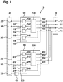
- Figure 1 shows a block diagram of an exemplary embodiment of the vehicle diagnostic device according to the invention.
- FIG. 3 shows a block diagram of a vehicle diagnostic device 2 according to an exemplary embodiment of the invention.
- the vehicle diagnostic device 2 has an interface device 10, a first data transmission device 100, a second data transmission device 200 and a data processing device 20.
- the interface device 10 is coupled to the first data transmission device 100 and the second data transmission device 200.
- the two data transmission devices 100 and 200 are in turn coupled to the data processing device 20. The details of these connections are described below.
- the first data transmission device 100 and the second data transmission device 200 have an identical structure. That is, they contain the same circuit elements which are connected to one another in the same way. Only the first data transmission device 100 is described in detail. To illustrate the identical structure, the elements of the first data transmission device 100 and the second data transmission device 200 are provided with corresponding reference symbols, the reference symbols of the second data transmission device 200 being increased by 100 compared to the reference symbols of the first data transmission device 100.
- the first data transmission device 100 has four interface-side connections, namely a first interface-side connection 102, a second interface-side connection 104, a third interface-side connection 106 and a fourth interface-side connection 108. Furthermore, the first data transmission device has six data processing-side connections, namely a first data processing-side connection 110, a second connection 112 on the data processing side, a third connection 114 on the data processing side, a fourth connection 116 on the data processing side, a fifth connection 118 on the data processing side and a sixth connection 120 on the data processing side. Furthermore, the first data transmission device 100 contains a switching matrix 130 and four diagnostic protocol driver circuits, namely a first diagnostic protocol driver circuit 140 second diagnostic protocol driver circuit 142, a third Diagnostic protocol driver circuit 144 and a fourth diagnostic protocol driver circuit 146.
- the first interface-side connection 102, the second interface-side connection 104 and the third interface-side connection 106 are connected to the switching matrix 130.
- the fourth interface-side connection 108 is connected to the switching matrix 130, to the fourth diagnostic protocol driver circuit 146 and to the sixth data-processing-side connection 120.
- the switching matrix 130 is connected to the first diagnostic protocol driver circuit 140, to the second diagnostic protocol driver circuit 142 and to the third diagnostic protocol driver circuit 144 as well as to the fourth connection 116 on the data processing side.
- the first diagnostic protocol driver circuit 140, the second diagnostic protocol driver circuit 142 and the third diagnostic protocol driver circuit 144 are connected to the first data processing-side connection 110, to the second data-processing-side connection 112 and to the third data-processing-side connection 114.
- the fourth diagnostic protocol driver circuit 146 is connected to the fifth data processing-side terminal 118.
- the first data transmission device 100 is in the form of an application-specific integrated circuit, the four interface-side connections and the six data processing-side connections are pins of the integrated circuit.
- the connections between the individual components are conductor tracks in the integrated circuit.
- the second data transmission device 200 is constructed identically to the first transmission device 100.
- the interface device 10 has four interface connections, namely a first interface connection 12, a second interface connection 14, a third interface connection 16 and a fourth interface connection 18.
- the interface device 10 has a standardized interface with which the vehicle diagnostic device 2 can be coupled to a corresponding interface of the vehicle , whereby data or signals can be exchanged between the vehicle diagnostic device 2 and the vehicle.
- the interface between the vehicle diagnostic device 2 and the vehicle can have any number of connections. In particular, there can be 4, 8, 16 or 32 connections.
- the exemplary use of four connections, as in Fig. 1 is used to simplify the description of the invention compared to a larger number of interface connections.
- the first interface connection 12 is coupled to the first interface connection 102 of the first data transmission device 100 and to the first interface connection 202 of the second data transmission device 200.
- the second interface connection 14 is coupled to the second interface connection 104 of the first data transmission device 100 and to the fourth interface connection 208 of the second data transmission device 200.
- the third interface connection 16 is coupled to the third interface connection of the first data transmission device 100 and to the second interface connection 204 of the second data transmission device 200.
- the fourth interface connection 18 is coupled to the fourth interface connection 108 of the first data transmission device 100 and to the third interface connection 206 of the second data transmission device 200.
- the data processing device 20 has six communication ports, namely a first communication port 22 and a second Communication port 24, a third communication port 26, a fourth communication port 28, a fifth communication port 30 and a sixth communication port 32.
- the first communication port 22, the second communication port 24 and the third communication port 26 are connected to the first data processing side port 110, the second data processing side port 112 and coupled to the fifth data processing-side connection 118 of the first data transmission device 100.
- the fourth communication port 28, the fifth communication port 30, and the sixth communication port 32 are coupled to the second data processing side port 112, the third data processing side port 214 and the sixth data processing side port 220 of the second data transmission device 200.
- the sixth communication port 32 and the sixth data processing-side port 220 of the second data transmission device 200 are connected to one another via an external diagnostic protocol driver circuit 40.
- interface-side connections and data processing-side connections do not refer to the geometric arrangement of the connections. Instead, the terms merely represent a differentiation between the connections that are intended for coupling to the interface device and the connections that are intended for coupling with the data processing device.
- the data processing device 20 initiates a desired one Diagnostic protocol by a corresponding signal to the corresponding diagnostic protocol driver circuit.
- the initiated diagnostic protocol driver circuit then causes the forwarding and, if necessary, processing of the data or signals relevant for the diagnostic protocol between the vehicle and the data processing device 20 through the first data transmission device 100 or through the second data transmission device 200.
- the data processing device 20 evaluates the received data or signals and determines whether and to what extent the tested component or components of the vehicle behave in accordance with their specification.
- the data processing device can store the result of this test or output it via an output device such as a display (not shown). It is also possible for the data processing device 20 to forward the results to a further unit, such as a maintenance computer, for example. This can be done in a wired or wireless way, the wireless way being preferred in many cases in portable vehicle diagnostic devices.
- data for programming control devices in the vehicle can also be fed to the vehicle via the data processing device 20.
- analog signals can be fed to an analog-to-digital converter via the data processing device 20 in order, for example, to enable a detailed diagnosis in the event of problems with establishing a connection or to activate a scan cycle.
- the data processing device 20 can execute at least five different diagnostic protocols. As in Fig. 1 As can be seen, the data processing device 20 can execute a first diagnostic protocol, a second diagnostic protocol and a fourth diagnostic protocol via the first diagnostic protocol driver circuit 140, the second diagnostic protocol driver circuit 142 and the fourth diagnostic protocol driver circuit 146 of the first data transmission device 100.
- the data processing device 20 can generate a third diagnosis protocol via the third diagnosis protocol driver circuit 244 and a fifth diagnosis protocol via the external diagnosis protocol driver circuit 40 To run.
- the data processing device 20 can either execute the second diagnostic protocol via the second data transmission device 200 or query a further diagnostic protocol via the communication connection 28.
- the reason for these two possibilities is the different couplings between the interface device 10 and the respective interface-side connections of the first and second data transmission devices 100, 200 Passes signals like the second diagnostic protocol driver circuit 142 of the first communication device.
- Different diagnostic protocols can also be implemented by controlling the switching matrix 130 and the switching matrix 230 in the two data transmission devices differently. It is possible that the switching matrix 130 (and thus also the switching matrix 230) is able to connect each of its inputs to each of its outputs, i.e. to enable any switching combination. However, it is also possible that the switching matrix 130 (and thus also the switching matrix 230) enables a limited number of switching combinations, in particular enables a limited number of parallel switching combinations at the same time. Since the two identical data transmission devices 100 and 200 are provided, each switching matrix 130 or 230 can be designed to be limited, the combination of the two switching matrices 130 and 230 providing the entire desired signal forwarding bandwidth. A less complex and inexpensive type of switching matrix can be provided which is sufficient for the flow of data in less complex applications and which, in combination with a further switching matrix, fulfills the switching capacity for complex applications.
- the data or signal transmission for the execution of different diagnostic protocols can be divided between the two data transmission devices 100, 200, the provision of the second data transmission device not only allowing faster, parallel operation of diagnostic protocols, but also additional flexibility the implementation of protocols.
Claims (6)
- Dispositif de diagnostic de véhicule (2) destiné à déterminer l'état d'au moins un composant d'un véhicule automobile, ledit dispositif comprenant :un moyen d'interface (10) qui peut être couplé à une interface de diagnostic du véhicule automobile,un premier dispositif de transmission de données (100) qui est couplé au moyen d'interface,un deuxième dispositif de transmission de données (200) qui est couplé au moyen d'interface, chacun des premier et deuxième dispositifs de transmission de données (100, 200) comportant une pluralité de circuits pilotes de protocole de diagnostic (140-146, 240-246), etun moyen de traitement de données (20) qui est couplé au premier et au deuxième dispositif de transmission de données (100, 200), le moyen de traitement de données (20) étant conçu pour exécuter différents protocoles de diagnostic par le biais du premier et du deuxième dispositif de transmission de données (100, 200),chacun des premier et deuxième dispositifs de transmission de données (100, 200) comportant une pluralité de connexions côté interface (102-108, 202-208) et au moins une partie des circuits pilotes de protocole de diagnostic respectifs (140-146, 240-246) étant couplée aux connexions côté interface (102-108, 202-208) par le biais d'au moins une matrice de commutation (130, 230),caractérisé en ce que le premier et le deuxième dispositif de transmission de données (100, 200) sont des circuits identiques,le moyen d'interface (10) comportant une pluralité de connexions d'interface (12-18), au moins un premier sous-ensemble de connexions côté interface (102-108) du premier dispositif de transmission de données (100) étant couplé aux connexions d'interface (12-18) et au moins un deuxième sous-ensemble de connexions côté interface (202-208) du deuxième dispositif de transmission de données (200) étant couplé aux connexions d'interface (12-18), le couplage des connexions côté interface (102-108) du premier dispositif de transmission de données (100) aux connexions d'interface (12-18) du moyen d'interface (10) étant différent du couplage des connexions côté interface (202-208) du deuxième dispositif de transmission de données (200) aux connexions d'interface (12-18) du moyen d'interface (10).
- Dispositif de diagnostic de véhicule (2) selon la revendication 1, le premier et le deuxième dispositif de transmission de données (100, 200) étant des circuits intégrés, en particulier des circuits intégrés à application spécifique (ASIC).
- Dispositif de diagnostic de véhicule (2) selon la revendication 1 ou 2, le moyen de traitement de données (10) étant couplé à un premier sous-groupe (140, 142, 146) de circuits pilotes de protocole de diagnostic (140, 142, 144, 146) du premier dispositif de transmission de données (100) et le moyen de traitement de données (10) étant couplé à un deuxième sous-groupe (242, 244) de circuits pilotes de protocole de diagnostic (240, 242, 244, 246) du deuxième dispositif de transmission de données (200), le premier sous-groupe étant différent du deuxième sous-groupe.
- Dispositif de diagnostic de véhicule (2) selon l'une des revendications 1 à 3, un ou plusieurs circuits pilotes de protocole de diagnostic extérieurs (40) étant couplés entre le dispositif de traitement de données (20) et l'un des premier et deuxième dispositifs de transmission de données (100, 200) ou les deux.
- Dispositif de diagnostic de véhicule (2) selon l'une des revendications 1 à 4, comprenant en outre au moins un autre dispositif de transmission de données, l'au moins un autre dispositif de transmission de données étant un circuit identique aux premier et deuxième dispositifs de transmission de données (100, 200) .
- Procédé de fonctionnement d'un dispositif de diagnostic de véhicule (2) selon l'une des revendications 1 à 5, le procédé comprenant les étapes suivantes :exécuter un premier protocole de diagnostic, la communication entre le moyen de traitement de données (20) et le moyen d'interface (10) se faisant par le biais du premier dispositif de transmission de données (100), etexécuter un deuxième protocole de diagnostic, la communication entre le moyen de traitement de données (20) et le moyen d'interface (10) se faisant par le biais du deuxième dispositif de transmission de données (200),les premier et deuxième dispositifs de transmission de données (100, 200) fonctionnant en parallèle de façon à exécuter différents protocoles de diagnostic simultanément.
Applications Claiming Priority (2)
| Application Number | Priority Date | Filing Date | Title |
|---|---|---|---|
| DE102014210238.3A DE102014210238A1 (de) | 2014-05-28 | 2014-05-28 | Fahrzeugdiagnosevorrichtung |
| PCT/EP2015/058033 WO2015180885A1 (fr) | 2014-05-28 | 2015-04-14 | Dispositif de diagnostic de véhicule et dispositif de transmission de données |
Publications (2)
| Publication Number | Publication Date |
|---|---|
| EP3149710A1 EP3149710A1 (fr) | 2017-04-05 |
| EP3149710B1 true EP3149710B1 (fr) | 2021-06-23 |
Family
ID=53039854
Family Applications (1)
| Application Number | Title | Priority Date | Filing Date |
|---|---|---|---|
| EP15719980.3A Active EP3149710B1 (fr) | 2014-05-28 | 2015-04-14 | Appareil pour diagnostiquer une véhicule et appareil de communication de données |
Country Status (5)
| Country | Link |
|---|---|
| US (1) | US10489990B2 (fr) |
| EP (1) | EP3149710B1 (fr) |
| AU (1) | AU2015266362B2 (fr) |
| DE (1) | DE102014210238A1 (fr) |
| WO (1) | WO2015180885A1 (fr) |
Families Citing this family (5)
| Publication number | Priority date | Publication date | Assignee | Title |
|---|---|---|---|---|
| US11961341B2 (en) | 2016-04-19 | 2024-04-16 | Mitchell International, Inc. | Systems and methods for determining likelihood of incident relatedness for diagnostic trouble codes |
| US10152836B2 (en) | 2016-04-19 | 2018-12-11 | Mitchell International, Inc. | Systems and methods for use of diagnostic scan tool in automotive collision repair |
| CN108189782A (zh) * | 2017-12-28 | 2018-06-22 | 深圳市元征科技股份有限公司 | 一种诊断设备 |
| CN110661847B (zh) * | 2019-08-28 | 2022-06-24 | 北京经纬恒润科技股份有限公司 | 车辆诊断方法以及装置 |
| CN111586145B (zh) * | 2020-04-30 | 2023-06-30 | 深圳市元征科技股份有限公司 | 一种车辆诊断方法、系统及电子设备和存储介质 |
Family Cites Families (27)
| Publication number | Priority date | Publication date | Assignee | Title |
|---|---|---|---|---|
| DE4011560A1 (de) | 1990-04-10 | 1991-10-17 | Conrads Johannes P F | Kombinierter hoehendifferenz-, neigungsmesser und kilometerzaehler fuer fahrzeuge |
| US5541840A (en) * | 1993-06-25 | 1996-07-30 | Chrysler Corporation | Hand held automotive diagnostic service tool |
| DE19731283B4 (de) * | 1997-07-21 | 2018-07-26 | Bayerische Motoren Werke Aktiengesellschaft | Diagnoseprüfgerät für elektronische Steuergeräte in unterschiedlichen Kraftfahrzeugtypen |
| US6772248B1 (en) * | 1999-03-26 | 2004-08-03 | Dearborn Group, Inc. | Protocol adapter for in-vehicle networks |
| US6662087B1 (en) * | 2000-01-03 | 2003-12-09 | Spx Corporation | Backward compatible diagnostic tool |
| US6718425B1 (en) * | 2000-05-31 | 2004-04-06 | Cummins Engine Company, Inc. | Handheld computer based system for collection, display and analysis of engine/vehicle data |
| US6603394B2 (en) * | 2000-12-08 | 2003-08-05 | Spx Corporation | Multi-protocol wireless communication module |
| US7149206B2 (en) * | 2001-02-08 | 2006-12-12 | Electronic Data Systems Corporation | System and method for managing wireless vehicular communications |
| US6920380B2 (en) * | 2002-09-18 | 2005-07-19 | Dearborn Group, Inc. | Protocol selection matrix for in-vehicle networks |
| US6816760B1 (en) * | 2003-05-13 | 2004-11-09 | Actron Manufacturing Company | Enclosure with interface device for facilitating communications between an electronic device and a vehicle diagnostic system |
| EP1735672A1 (fr) * | 2004-04-01 | 2006-12-27 | Delphi Technologies, Inc. | Procede et protocole pour des diagnostics de reseaux arbitrairement complexes de dispositifs |
| US7805228B2 (en) * | 2004-08-19 | 2010-09-28 | Spx Corporation | Vehicle diagnostic device |
| US7248954B2 (en) * | 2005-03-23 | 2007-07-24 | Spx Corporation | Integrated circuit vehicle diagnostics interface adapter apparatus and method |
| US8065048B2 (en) * | 2006-09-14 | 2011-11-22 | Spx Corporation | Automatically identifying volvo communication protocols method and apparatus |
| DE102007012304A1 (de) * | 2007-03-14 | 2008-09-18 | Robert Bosch Gmbh | Schnittstelle in einem Fahrzeug und Verfahren zum Datenaustausch |
| US8630766B2 (en) * | 2008-05-20 | 2014-01-14 | Bosch Automotive Service Solutions Llc | Universal vehicle input/output transceiver and method of operation thereof |
| US8316876B2 (en) * | 2008-07-17 | 2012-11-27 | John C. Kupferle Foundry Company | Flushing device with removable drain ring for potable water systems |
| US8489796B2 (en) * | 2008-07-18 | 2013-07-16 | Dearborn Group, Inc. | Wireless protocol adapter assembly with interchangeable connectors |
| IT1394809B1 (it) * | 2009-06-04 | 2012-07-13 | Texa Spa | Modulo diagnostico di bordo programmabile, accoppiabile ad una presa diagnostica veicolare |
| US8700254B2 (en) * | 2009-10-23 | 2014-04-15 | Intelligent Mechatronic Systems Inc. | Hardware reconfigurable vehicle on-board diagnostic interface and telematic system |
| US8688313B2 (en) * | 2010-12-23 | 2014-04-01 | Aes Technologies, Llc. | Remote vehicle programming system and method |
| US8626375B2 (en) * | 2011-03-04 | 2014-01-07 | Bosch Automotive Service Solutions Llc | Multiplexing device with provision for expansion |
| US8788139B2 (en) * | 2011-03-21 | 2014-07-22 | Webtech Wireless Inc. | Multi-protocol vehicle diagnostic interface device and method |
| AT510379B1 (de) * | 2011-12-12 | 2012-09-15 | Ditest Fahrzeugdiagnose Gmbh | Diagnosetool zum anschluss an eine fahrzeug-diagnosebuchse |
| DE102013224344A1 (de) * | 2013-11-28 | 2015-05-28 | Robert Bosch Gmbh | Vorrichtung und Verfahren zum Prüfen einer Fahrzeugbatterie |
| DE102014204128A1 (de) * | 2014-03-06 | 2015-09-10 | Robert Bosch Gmbh | Elektronische Einheit für eine Fahrzeugkommunikationsschnittstelle |
| US10152836B2 (en) * | 2016-04-19 | 2018-12-11 | Mitchell International, Inc. | Systems and methods for use of diagnostic scan tool in automotive collision repair |
-
2014
- 2014-05-28 DE DE102014210238.3A patent/DE102014210238A1/de not_active Withdrawn
-
2015
- 2015-04-14 US US15/314,338 patent/US10489990B2/en active Active
- 2015-04-14 EP EP15719980.3A patent/EP3149710B1/fr active Active
- 2015-04-14 AU AU2015266362A patent/AU2015266362B2/en active Active
- 2015-04-14 WO PCT/EP2015/058033 patent/WO2015180885A1/fr active Application Filing
Non-Patent Citations (1)
| Title |
|---|
| None * |
Also Published As
| Publication number | Publication date |
|---|---|
| US20170200327A1 (en) | 2017-07-13 |
| US10489990B2 (en) | 2019-11-26 |
| WO2015180885A1 (fr) | 2015-12-03 |
| AU2015266362B2 (en) | 2018-05-10 |
| EP3149710A1 (fr) | 2017-04-05 |
| AU2015266362A1 (en) | 2016-06-30 |
| DE102014210238A1 (de) | 2015-12-03 |
Similar Documents
| Publication | Publication Date | Title |
|---|---|---|
| EP3149710B1 (fr) | Appareil pour diagnostiquer une véhicule et appareil de communication de données | |
| EP1450223B1 (fr) | Circuit d'interface universel configurable pour formé l'interface d'entrée/sortie d'un processus | |
| DE102018209407A1 (de) | Verfahren und Vorrichtung zur Behandlung einer Anomalie in einem Kommunikationsnetzwerk | |
| DE2813418A1 (de) | Einrichtung in einer elektronischen datenverarbeitungsanlage zur meldung von fehler- und betriebszustaenden | |
| EP1796051B1 (fr) | Dispositifs de diagnostic dans un véhicule doté d'une unité d'informations de diagnostic pour un module de diagnostic | |
| DE102016000126A1 (de) | Serielles Bussystem mit Koppelmodulen | |
| DE19749068A1 (de) | Verfahren und Vorrichtung zur Überwachung eines Rechnersystems bestehend aus wenigstens zwei Prozessoren | |
| DE102016220197A1 (de) | Verfahren zum Verarbeiten von Daten für ein automatisiertes Fahrzeug | |
| DE102006020562A1 (de) | Anordnung und Verfahren zur Reprogrammierung von Steuergeräten | |
| DE102007040216A1 (de) | System zur Ansteuerung eines Rotorantriebes einer Offenend-Rotorspinnmaschine | |
| EP1410577B1 (fr) | Elements reseau destines a un reseau optique ayant une fonction de securite, en particulier a un reseau optique a topologie annulaire | |
| DE102019111564A1 (de) | Verfahren und system zum konfigurieren von filterobjekten für eine controller area network-steuerung | |
| EP1532497A2 (fr) | Procede, dispositif et systeme pour afficher les donnees d'un systeme de commande de machine | |
| DE112021001247T5 (de) | Übertragungssystem, dessen serialisierer, deserialisierer, signalverarbeitungssystem, und kraftfahrzeug | |
| DE102016003013B4 (de) | Überwachungsvorrichtung und Verfahren zum Überwachen eines Betriebs eines Steuergeräts eines Kraftfahrzeugs | |
| EP1099952A1 (fr) | Cellule de circuit avec fonction d'auto-test intégré et procédé pour essayer ledit circuit | |
| DE10239846B4 (de) | Fail-Silent-Steuergerät | |
| DE102007019048A1 (de) | Modulare automatisierungstechnische Einrichtung | |
| EP4351004A1 (fr) | Dispositif d'enregistrement à configuration automatique pour données d'image à partir d'un dispositif de détection d'imagerie | |
| EP3720056B1 (fr) | Procédé et système d'analyse parallèle en temps réel lors des essais fonctionnels du matériel et du logiciel des appareils de commande | |
| DE102008045961B4 (de) | Schnittstelle für mehrere Empfänger und eine Widerstandskette | |
| DE102016206774A1 (de) | Verfahren zum Betreiben eines Kommunikationssystems für ein Fahrzeug und Kommunikationssystem | |
| DE102014216993A1 (de) | Kommunikationssystem für Kraftfahrzeug mit Elektroantrieb | |
| WO2008098999A1 (fr) | Système de commande d'un dispositif technique | |
| DE102022129104A1 (de) | Verfahren zum Konfigurieren einer Steuervorrichtung für eine Mehrzahl von Elektromotoren, Steuervorrichtung, System und Fahrzeug |
Legal Events
| Date | Code | Title | Description |
|---|---|---|---|
| STAA | Information on the status of an ep patent application or granted ep patent |
Free format text: STATUS: THE INTERNATIONAL PUBLICATION HAS BEEN MADE |
|
| PUAI | Public reference made under article 153(3) epc to a published international application that has entered the european phase |
Free format text: ORIGINAL CODE: 0009012 |
|
| STAA | Information on the status of an ep patent application or granted ep patent |
Free format text: STATUS: REQUEST FOR EXAMINATION WAS MADE |
|
| 17P | Request for examination filed |
Effective date: 20170102 |
|
| AK | Designated contracting states |
Kind code of ref document: A1 Designated state(s): AL AT BE BG CH CY CZ DE DK EE ES FI FR GB GR HR HU IE IS IT LI LT LU LV MC MK MT NL NO PL PT RO RS SE SI SK SM TR |
|
| AX | Request for extension of the european patent |
Extension state: BA ME |
|
| DAV | Request for validation of the european patent (deleted) | ||
| DAX | Request for extension of the european patent (deleted) | ||
| STAA | Information on the status of an ep patent application or granted ep patent |
Free format text: STATUS: EXAMINATION IS IN PROGRESS |
|
| 17Q | First examination report despatched |
Effective date: 20191010 |
|
| RAP1 | Party data changed (applicant data changed or rights of an application transferred) |
Owner name: ROBERT BOSCH GMBH |
|
| RIC1 | Information provided on ipc code assigned before grant |
Ipc: G07C 5/00 20060101AFI20201208BHEP Ipc: G07C 5/08 20060101ALI20201208BHEP |
|
| GRAP | Despatch of communication of intention to grant a patent |
Free format text: ORIGINAL CODE: EPIDOSNIGR1 |
|
| STAA | Information on the status of an ep patent application or granted ep patent |
Free format text: STATUS: GRANT OF PATENT IS INTENDED |
|
| INTG | Intention to grant announced |
Effective date: 20210125 |
|
| GRAS | Grant fee paid |
Free format text: ORIGINAL CODE: EPIDOSNIGR3 |
|
| GRAA | (expected) grant |
Free format text: ORIGINAL CODE: 0009210 |
|
| STAA | Information on the status of an ep patent application or granted ep patent |
Free format text: STATUS: THE PATENT HAS BEEN GRANTED |
|
| AK | Designated contracting states |
Kind code of ref document: B1 Designated state(s): AL AT BE BG CH CY CZ DE DK EE ES FI FR GB GR HR HU IE IS IT LI LT LU LV MC MK MT NL NO PL PT RO RS SE SI SK SM TR |
|
| REG | Reference to a national code |
Ref country code: GB Ref legal event code: FG4D Free format text: NOT ENGLISH |
|
| REG | Reference to a national code |
Ref country code: CH Ref legal event code: EP |
|
| REG | Reference to a national code |
Ref country code: DE Ref legal event code: R096 Ref document number: 502015014853 Country of ref document: DE Ref country code: AT Ref legal event code: REF Ref document number: 1404972 Country of ref document: AT Kind code of ref document: T Effective date: 20210715 |
|
| REG | Reference to a national code |
Ref country code: IE Ref legal event code: FG4D Free format text: LANGUAGE OF EP DOCUMENT: GERMAN |
|
| REG | Reference to a national code |
Ref country code: LT Ref legal event code: MG9D |
|
| PG25 | Lapsed in a contracting state [announced via postgrant information from national office to epo] |
Ref country code: BG Free format text: LAPSE BECAUSE OF FAILURE TO SUBMIT A TRANSLATION OF THE DESCRIPTION OR TO PAY THE FEE WITHIN THE PRESCRIBED TIME-LIMIT Effective date: 20210923 Ref country code: HR Free format text: LAPSE BECAUSE OF FAILURE TO SUBMIT A TRANSLATION OF THE DESCRIPTION OR TO PAY THE FEE WITHIN THE PRESCRIBED TIME-LIMIT Effective date: 20210623 Ref country code: FI Free format text: LAPSE BECAUSE OF FAILURE TO SUBMIT A TRANSLATION OF THE DESCRIPTION OR TO PAY THE FEE WITHIN THE PRESCRIBED TIME-LIMIT Effective date: 20210623 Ref country code: LT Free format text: LAPSE BECAUSE OF FAILURE TO SUBMIT A TRANSLATION OF THE DESCRIPTION OR TO PAY THE FEE WITHIN THE PRESCRIBED TIME-LIMIT Effective date: 20210623 |
|
| PG25 | Lapsed in a contracting state [announced via postgrant information from national office to epo] |
Ref country code: NO Free format text: LAPSE BECAUSE OF FAILURE TO SUBMIT A TRANSLATION OF THE DESCRIPTION OR TO PAY THE FEE WITHIN THE PRESCRIBED TIME-LIMIT Effective date: 20210923 Ref country code: RS Free format text: LAPSE BECAUSE OF FAILURE TO SUBMIT A TRANSLATION OF THE DESCRIPTION OR TO PAY THE FEE WITHIN THE PRESCRIBED TIME-LIMIT Effective date: 20210623 Ref country code: SE Free format text: LAPSE BECAUSE OF FAILURE TO SUBMIT A TRANSLATION OF THE DESCRIPTION OR TO PAY THE FEE WITHIN THE PRESCRIBED TIME-LIMIT Effective date: 20210623 Ref country code: LV Free format text: LAPSE BECAUSE OF FAILURE TO SUBMIT A TRANSLATION OF THE DESCRIPTION OR TO PAY THE FEE WITHIN THE PRESCRIBED TIME-LIMIT Effective date: 20210623 Ref country code: GR Free format text: LAPSE BECAUSE OF FAILURE TO SUBMIT A TRANSLATION OF THE DESCRIPTION OR TO PAY THE FEE WITHIN THE PRESCRIBED TIME-LIMIT Effective date: 20210924 |
|
| REG | Reference to a national code |
Ref country code: NL Ref legal event code: MP Effective date: 20210623 |
|
| PG25 | Lapsed in a contracting state [announced via postgrant information from national office to epo] |
Ref country code: ES Free format text: LAPSE BECAUSE OF FAILURE TO SUBMIT A TRANSLATION OF THE DESCRIPTION OR TO PAY THE FEE WITHIN THE PRESCRIBED TIME-LIMIT Effective date: 20210623 Ref country code: RO Free format text: LAPSE BECAUSE OF FAILURE TO SUBMIT A TRANSLATION OF THE DESCRIPTION OR TO PAY THE FEE WITHIN THE PRESCRIBED TIME-LIMIT Effective date: 20210623 Ref country code: PT Free format text: LAPSE BECAUSE OF FAILURE TO SUBMIT A TRANSLATION OF THE DESCRIPTION OR TO PAY THE FEE WITHIN THE PRESCRIBED TIME-LIMIT Effective date: 20211025 Ref country code: NL Free format text: LAPSE BECAUSE OF FAILURE TO SUBMIT A TRANSLATION OF THE DESCRIPTION OR TO PAY THE FEE WITHIN THE PRESCRIBED TIME-LIMIT Effective date: 20210623 Ref country code: SM Free format text: LAPSE BECAUSE OF FAILURE TO SUBMIT A TRANSLATION OF THE DESCRIPTION OR TO PAY THE FEE WITHIN THE PRESCRIBED TIME-LIMIT Effective date: 20210623 Ref country code: SK Free format text: LAPSE BECAUSE OF FAILURE TO SUBMIT A TRANSLATION OF THE DESCRIPTION OR TO PAY THE FEE WITHIN THE PRESCRIBED TIME-LIMIT Effective date: 20210623 Ref country code: EE Free format text: LAPSE BECAUSE OF FAILURE TO SUBMIT A TRANSLATION OF THE DESCRIPTION OR TO PAY THE FEE WITHIN THE PRESCRIBED TIME-LIMIT Effective date: 20210623 Ref country code: CZ Free format text: LAPSE BECAUSE OF FAILURE TO SUBMIT A TRANSLATION OF THE DESCRIPTION OR TO PAY THE FEE WITHIN THE PRESCRIBED TIME-LIMIT Effective date: 20210623 |
|
| PG25 | Lapsed in a contracting state [announced via postgrant information from national office to epo] |
Ref country code: PL Free format text: LAPSE BECAUSE OF FAILURE TO SUBMIT A TRANSLATION OF THE DESCRIPTION OR TO PAY THE FEE WITHIN THE PRESCRIBED TIME-LIMIT Effective date: 20210623 |
|
| REG | Reference to a national code |
Ref country code: DE Ref legal event code: R097 Ref document number: 502015014853 Country of ref document: DE |
|
| PG25 | Lapsed in a contracting state [announced via postgrant information from national office to epo] |
Ref country code: DK Free format text: LAPSE BECAUSE OF FAILURE TO SUBMIT A TRANSLATION OF THE DESCRIPTION OR TO PAY THE FEE WITHIN THE PRESCRIBED TIME-LIMIT Effective date: 20210623 |
|
| PLBE | No opposition filed within time limit |
Free format text: ORIGINAL CODE: 0009261 |
|
| STAA | Information on the status of an ep patent application or granted ep patent |
Free format text: STATUS: NO OPPOSITION FILED WITHIN TIME LIMIT |
|
| 26N | No opposition filed |
Effective date: 20220324 |
|
| PG25 | Lapsed in a contracting state [announced via postgrant information from national office to epo] |
Ref country code: AL Free format text: LAPSE BECAUSE OF FAILURE TO SUBMIT A TRANSLATION OF THE DESCRIPTION OR TO PAY THE FEE WITHIN THE PRESCRIBED TIME-LIMIT Effective date: 20210623 |
|
| REG | Reference to a national code |
Ref country code: CH Ref legal event code: PL |
|
| REG | Reference to a national code |
Ref country code: BE Ref legal event code: MM Effective date: 20220430 |
|
| PG25 | Lapsed in a contracting state [announced via postgrant information from national office to epo] |
Ref country code: MC Free format text: LAPSE BECAUSE OF FAILURE TO SUBMIT A TRANSLATION OF THE DESCRIPTION OR TO PAY THE FEE WITHIN THE PRESCRIBED TIME-LIMIT Effective date: 20210623 Ref country code: LU Free format text: LAPSE BECAUSE OF NON-PAYMENT OF DUE FEES Effective date: 20220414 Ref country code: LI Free format text: LAPSE BECAUSE OF NON-PAYMENT OF DUE FEES Effective date: 20220430 Ref country code: CH Free format text: LAPSE BECAUSE OF NON-PAYMENT OF DUE FEES Effective date: 20220430 |
|
| PG25 | Lapsed in a contracting state [announced via postgrant information from national office to epo] |
Ref country code: BE Free format text: LAPSE BECAUSE OF NON-PAYMENT OF DUE FEES Effective date: 20220430 |
|
| PG25 | Lapsed in a contracting state [announced via postgrant information from national office to epo] |
Ref country code: IE Free format text: LAPSE BECAUSE OF NON-PAYMENT OF DUE FEES Effective date: 20220414 |
|
| REG | Reference to a national code |
Ref country code: AT Ref legal event code: MM01 Ref document number: 1404972 Country of ref document: AT Kind code of ref document: T Effective date: 20220414 |
|
| PG25 | Lapsed in a contracting state [announced via postgrant information from national office to epo] |
Ref country code: AT Free format text: LAPSE BECAUSE OF NON-PAYMENT OF DUE FEES Effective date: 20220414 |
|
| PGFP | Annual fee paid to national office [announced via postgrant information from national office to epo] |
Ref country code: IT Payment date: 20230428 Year of fee payment: 9 Ref country code: FR Payment date: 20230417 Year of fee payment: 9 Ref country code: DE Payment date: 20230627 Year of fee payment: 9 |
|
| PGFP | Annual fee paid to national office [announced via postgrant information from national office to epo] |
Ref country code: GB Payment date: 20230420 Year of fee payment: 9 |
|
| PG25 | Lapsed in a contracting state [announced via postgrant information from national office to epo] |
Ref country code: HU Free format text: LAPSE BECAUSE OF FAILURE TO SUBMIT A TRANSLATION OF THE DESCRIPTION OR TO PAY THE FEE WITHIN THE PRESCRIBED TIME-LIMIT; INVALID AB INITIO Effective date: 20150414 |
|
| PG25 | Lapsed in a contracting state [announced via postgrant information from national office to epo] |
Ref country code: MK Free format text: LAPSE BECAUSE OF FAILURE TO SUBMIT A TRANSLATION OF THE DESCRIPTION OR TO PAY THE FEE WITHIN THE PRESCRIBED TIME-LIMIT Effective date: 20210623 Ref country code: CY Free format text: LAPSE BECAUSE OF FAILURE TO SUBMIT A TRANSLATION OF THE DESCRIPTION OR TO PAY THE FEE WITHIN THE PRESCRIBED TIME-LIMIT Effective date: 20210623 |