EP3149427B2 - Electric reactive armour - Google Patents
Electric reactive armour Download PDFInfo
- Publication number
- EP3149427B2 EP3149427B2 EP15732971.5A EP15732971A EP3149427B2 EP 3149427 B2 EP3149427 B2 EP 3149427B2 EP 15732971 A EP15732971 A EP 15732971A EP 3149427 B2 EP3149427 B2 EP 3149427B2
- Authority
- EP
- European Patent Office
- Prior art keywords
- electrode
- metal plate
- electrically conductive
- armour
- conductive structure
- Prior art date
- Legal status (The legal status is an assumption and is not a legal conclusion. Google has not performed a legal analysis and makes no representation as to the accuracy of the status listed.)
- Active
Links
- 229910052751 metal Inorganic materials 0.000 claims description 56
- 239000002184 metal Substances 0.000 claims description 56
- 239000000463 material Substances 0.000 claims description 15
- 239000004020 conductor Substances 0.000 claims description 13
- 239000011888 foil Substances 0.000 claims description 12
- 239000011810 insulating material Substances 0.000 claims description 9
- 230000000149 penetrating effect Effects 0.000 claims description 8
- 239000007787 solid Substances 0.000 claims description 7
- 230000035515 penetration Effects 0.000 claims description 6
- 238000000034 method Methods 0.000 claims description 5
- 239000003990 capacitor Substances 0.000 description 5
- 239000012777 electrically insulating material Substances 0.000 description 5
- 230000000694 effects Effects 0.000 description 3
- 239000007772 electrode material Substances 0.000 description 3
- 230000007123 defense Effects 0.000 description 2
- 230000008020 evaporation Effects 0.000 description 2
- 238000001704 evaporation Methods 0.000 description 2
- 238000004904 shortening Methods 0.000 description 2
- 229910000831 Steel Inorganic materials 0.000 description 1
- 238000007792 addition Methods 0.000 description 1
- 239000004411 aluminium Substances 0.000 description 1
- 229910052782 aluminium Inorganic materials 0.000 description 1
- XAGFODPZIPBFFR-UHFFFAOYSA-N aluminium Chemical compound [Al] XAGFODPZIPBFFR-UHFFFAOYSA-N 0.000 description 1
- 230000007423 decrease Effects 0.000 description 1
- 230000001687 destabilization Effects 0.000 description 1
- 230000000368 destabilizing effect Effects 0.000 description 1
- 230000001066 destructive effect Effects 0.000 description 1
- 239000006260 foam Substances 0.000 description 1
- 238000010438 heat treatment Methods 0.000 description 1
- 239000006262 metallic foam Substances 0.000 description 1
- 230000000116 mitigating effect Effects 0.000 description 1
- 238000012986 modification Methods 0.000 description 1
- 230000004048 modification Effects 0.000 description 1
- 239000004033 plastic Substances 0.000 description 1
- 239000002984 plastic foam Substances 0.000 description 1
- 239000011148 porous material Substances 0.000 description 1
- 239000010959 steel Substances 0.000 description 1
Images

Classifications
-
- F—MECHANICAL ENGINEERING; LIGHTING; HEATING; WEAPONS; BLASTING
- F41—WEAPONS
- F41H—ARMOUR; ARMOURED TURRETS; ARMOURED OR ARMED VEHICLES; MEANS OF ATTACK OR DEFENCE, e.g. CAMOUFLAGE, IN GENERAL
- F41H5/00—Armour; Armour plates
- F41H5/007—Reactive armour; Dynamic armour
-
- B—PERFORMING OPERATIONS; TRANSPORTING
- B63—SHIPS OR OTHER WATERBORNE VESSELS; RELATED EQUIPMENT
- B63G—OFFENSIVE OR DEFENSIVE ARRANGEMENTS ON VESSELS; MINE-LAYING; MINE-SWEEPING; SUBMARINES; AIRCRAFT CARRIERS
- B63G13/00—Other offensive or defensive arrangements on vessels; Vessels characterised thereby
-
- F—MECHANICAL ENGINEERING; LIGHTING; HEATING; WEAPONS; BLASTING
- F41—WEAPONS
- F41H—ARMOUR; ARMOURED TURRETS; ARMOURED OR ARMED VEHICLES; MEANS OF ATTACK OR DEFENCE, e.g. CAMOUFLAGE, IN GENERAL
- F41H5/00—Armour; Armour plates
- F41H5/02—Plate construction
- F41H5/04—Plate construction composed of more than one layer
- F41H5/0442—Layered armour containing metal
-
- F—MECHANICAL ENGINEERING; LIGHTING; HEATING; WEAPONS; BLASTING
- F41—WEAPONS
- F41H—ARMOUR; ARMOURED TURRETS; ARMOURED OR ARMED VEHICLES; MEANS OF ATTACK OR DEFENCE, e.g. CAMOUFLAGE, IN GENERAL
- F41H7/00—Armoured or armed vehicles
- F41H7/02—Land vehicles with enclosing armour, e.g. tanks
- F41H7/04—Armour construction
Definitions
- the present invention relates to electric reactive armour (ELRA), a system for protecting a vehicle or a vessel containing such an electric reactive armour, a vehicle or a vessel provided with such a system. Furthermore the invention provides a method of protecting a vehicle or a vessel.
- ELRA electric reactive armour
- An electric reactive armour comprises a first electrode and a second electrode spaced apart from the first electrode, to which electrodes a high voltage can be applied so as to disrupt a charge that impacts on the electric reactive armour.
- Such an armour is known from European Patent EP 1 877 720 & United States Patent US 8 006 607 (Fraunhofer-Gesellschaft).
- the known armour is designed to protect an object from threats such as shaped charges, for example RPGs (Rocket Propelled Grenades).
- RPGs Rocket Propelled Grenades
- the charge of an RPG produces a high speed jet of typically molten metal, which has a high penetrating power.
- the jet effectively creates a short circuit when it has penetrated the first electrode and reaches the second electrode.
- a strong electrical current will flow through the jet, which gives rise to a magnetic field that in turn gives rise to a Lorentz force on the jet. This disturbs the jet and distorts its needle shape, thus significantly reducing its penetrating power.
- European Patent EP 1 877 720 discloses a second electrode which is made of a spatially heterogeneous material, such as open-pore aluminium foam.
- the patent states that the electrode material should have a very good electrical conductivity.
- Using such a spatially heterogeneous electrode material apparently causes electrode material to be displaced in a direction away from the longitudinal axis of the jet, thus increasing the disturbance of the jet.
- Bulgarian utility model application BG 103643 discloses an electric armour with two parallel walls and plurality of inclined, electrically conductive plates between the walls, at an angle of between 10 to 30 degrees to the walls. The inclined plates are mechanically connected to each other.
- One pole of an electric voltage source is connected to both walls and another pole is connected to a conductive element that runs in parallel with the walls, midway between the walls.
- the inclined plates are connected to the conductive element. When a projectile hits the outer wall, this gives rise to electrical contact between an inclined plate and the wall arises.
- the publication discloses that the described solution results in immediate electrical contact after piercing or deformation, because of the minimal distance between the walls and the inclined plates. The contact continues during passage of the projectile through the armour.
- the plates also serve to deflect the projectile JP2002295996 discloses a missile defense of an armored vehicle, wherein the missile defense comprises a stack of parallel electrode plates with capacitors connected between successive electrode plates.
- EP1877720 discloses an object protection device with an electrode array to which a voltage is applied.
- the electrode facing the object comprises an area with a metal foam that may have a honeycomb structure.
- WO2010082970 discloses an electromagnetic armor system with a honeycomb structured open-cell lattice core between two conductive layers.
- the electrodes each comprise a metal plate, the metal plates extending in parallel to each other, and the surfaces extend in parallel with the metal plates in a stack of surfaces between the metal plates. In this way the largest number of surfaces can be realized in a distance D between the metal plates, given the distances between successive surfaces.
- an electric reactive armour comprising a first metal plate and a second metal plate insulated from the first metal plate.
- the second metal plate extends in parallel with the first metal plate.
- Insulating material is provided between the first and second plate and connectors are provided coupled to the first and second metal plate respectively, for applying an electric voltage between the first and second metal plate.
- An electrically conductive structure is provided comprising a plurality of layers of electrical conductor material located between the first and second metal plate embedded in the insulating material, the layers of electrical conductor material being electrically coupled to each other and preferably to the second metal plate.
- the layers of electrical conductor material are arranged such that a charge penetrating the first metal plate will penetrate the layers of electrical conductor material successively.
- the first and second metal plate extend parallel to each other and the layers of electrical conductor material extend in parallel to the first and second metal plate.
- an electrically conductive structure having a plurality of surfaces embedded in an insulating material, such that a jet due the charge penetrates successive surfaces of the electrically conductive structure, it is accomplished that the electrical point of contact of the tip of the jet is renewed in a stepwise manner without need to interrupt the current.
- This stepwise renewal of the point of contact serves to destabilize the jet. It may cause the initially needle-shaped jet to form a series of relatively broad discs. That is, the electrical current caused by the stepwise penetration distorts the jet in such a manner, that it is blunted and effectively fragmented. As a result, the jet will penetrate the second electrode is penetrated over a smaller distance and the jet may be stopped altogether. The more successive surfaces are used, the stronger the effect of destabilization of the jet.
- the conductive structure also causes an early onset of the current, which further assists in the distortion of the jet.
- the surfaces are electrically connected in series, configured such that, in case of a short circuit between the first electrode and one of the surfaces that is closest to the first electrode, a short circuit current to said one of the surfaces that is closest to the first electrode flows successively through successive ones of the surfaces that are successively closer to the first electrode. This reduces a delay involved with build up of current when the contact is renewed.
- the electrically conductive structure comprises a meandering structure.
- a meandering structure preferably has main surfaces which extend substantially parallel to each other, which main surfaces are connected by curved surfaces and/or by surfaces arranged at an angle of, for example, 900 relative to the main surfaces.
- a meandering structure has the advantage of being simple yet effective.
- each cavity may extend substantially through the width of the structure, or may be small relative to said width, and is on several sides surrounded by conductive surfaces.
- the electrically conductive structure comprises a plurality of electrically conductive elements made of conductive foil, such as metal foil.
- the electrically conductive elements may each constitute a hexagonal cylinder or a hexagonal torus.
- the conductive structure may be constituted by stacking three-dimensional elements, such as cylinders. It is noted that other embodiments, such as the meandering conductive structure mentioned above, may also be made of conductive foil.
- the second electrode further comprises a base element on which the electrically conductive structure is mounted and to which it is electrically connected, which base element preferably comprises a solid metal plate.
- the second electrode is constituted by both an embedded conductive structure for disrupting the charge, and a metal plate for providing mechanical protection. It will be understood that the embedded conductive structure is mounted in the base element in such a way that the structure faces the jet, so that the jet will reach the structure before it reaches the base element.
- An armour as defined above is provided, further comprising a stripper plate arranged between the first electrode and the second electrode for reducing the width of the charge and/or for providing further mechanical resistance.
- the stripper plate may, for example, be made of metal, such as armour quality metal.
- a system for protecting a vehicle or a vessel like an armoured boat comprising at least one high voltage source and an electric reactive armour as defined above.
- a vehicle or vessel is provided with a system as defined above.
- a method of protecting a vehicle or a vessel is proviced, the method comprising the step of applying a system as defined above.
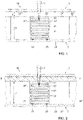
- the electric reactive armour (ELRA) 10 shown merely by way of nonlimiting example in Fig. 1 comprises a first electrode 1 and a second electrode 2, which electrodes are spaced apart at a distance (D+d).
- First and second electrode 1, 2 comprise a first and second metal plate respectively.
- the electric reactive armour 10 comprises an electrically conductive structure 21, comprising a plurality of surfaces 22, i.e. layers of electrical conductor material, located between the first and second metal plate, extending transverse to a direction from the first metal plate to the second metal plate, preferably in parallel to the first and second metal plate
- the plurality of surfaces 22 of the electrically conductive structure 21 are in electrical contact with the second metal plate, and normally electrically isolated from the first metal plate.
- the electrically conductive structure 21 may be considered to be part of the second electrode 2. As shown, a plurality of electrically conductive structures 21 may be provided in parallel at different locations on the second metal plate. The figures only show a section of the electric reactive armour wherein one or more of these electrically conductive structures 21 are present, but it should be appreciated that the electric reactive armour may extend further and more electrically conductive structures 21 may be present.
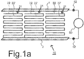
- Fig.1a schematically shows an armour system comprsising such an electric reactive armour 10 and an electrical power source 50 connected between the first electrode 1 and the second electrode 2.
- the electric reactive armour 10 may comprise connectors 52 coupled to first electrode 1 and a second electrode 2 for electrically connecting electrical power source 50 to first electrode 1 and a second electrode 2.
- Electrical power source 50 may comprise a capacitor connected between first electrode 1 and a second electrode 2.
- a high electric voltage can be applied to the electrodes using a suitable electrical power source 50, such as a capacitor.
- Typical suitable voltages range between 1000 and 5000 V, depending on the application and on the dimensioning of the armour.
- the power source should be capable of supplying a strong current during a short period of time, for example 100 to 500 kA during 100 ⁇ s, or 1000 kA during 50 ⁇ s.
- the capacitor may be located on the electrode side of the connectors 52. This reduces power dissipation by the connectors. Again, the current to be supplied will depend on the application and the dimensioning of the armour.
- the first electrode 1 will face away from the object to be protected, such as the interior of a vehicle, a boat, a tank or other vessel, while the second electrode 2 will face towards said object.
- the first electrode 1 is constituted by a metal plate, made of armour quality metal.
- the second electrode 2 of Fig. 1 also comprises a metal plate 29, which preferably is also made of armour quality metal so as to resist bullets and other projectiles.
- the metal plates that form first and second electrode 1, 2 are preferably parallel to each other.
- projectiles are capable of producing a jet of molten metal upon impact.
- Such projectiles may be rocket propelled grenades (RPGs), the charge of which typically produces such a jet.
- RPGs rocket propelled grenades
- Most armour plates are not capable of withstanding such charges, unless the plates are very thick. However, thick armour plates are necessarily heavy, and make it unfeasible to use such thick plates in vehicles, boats and other small vessels.
- Electric reactive armour ELRA
- ELRA Electric reactive armour
- the electric reactive armour is designed to disrupt the jet even more.
- the second electrode 2 comprises a series of arrangements 20, 20', 20" ..., each constituted by an electrically conductive structure 21 having a plurality of surfaces 22 embedded in an insulating material 23.
- the surfaces 22 need not be designed to resist charges. Instead, the surfaces 22 are designed to be penetrated by the jet 7. However, a certain resistance to the jet 7 may be desirable in some embodiments. In preferred embodiments, however, the surfaces 22, 22', ... , and typically the entire structure 21, is made of relatively thin electrically conductive foil.
- the electrically conductive foil forms the surfaces 22, 22'... (i.e. layers of electrical conductor material) as well as the electrical connections between successive ones of the surfaces 22, 22'...at the edges of the surfaces 22, 22'....
- a meandering current path will arise when a short circuit arises between the surface 22 nearest first electrode 1 and that first electrode 1.
- the current will flow alternately in opposite directions parallel to the plane of the first electrode 1, and towards the first electrode in alternate opposite sides of the surfaces (layers).
- the current will flow through a first one of the surfaces in a first direction parallel with the plane of first electrode 1.
- the current flows in a direction towards that plane to an adjacent second one of the surfaces, at the edge of the surfaces where the foil runs from the first one of the surfaces to the second one of the surfaces.
- the current flows through the second one of the surfaces in a second direction parallel to said plane, but opposite to the first direction.
- the edges of the surfaces may be electrically connected to supply conductors (not shown) that extend from the second electrode 2 in the direction of the first electrode 1. This has the effect that when a short circuit arises between a surface and first electrode 1, time is needed to build up electrical current.
- a foil that meanders to form the surfaces has the advantage that less time is needed to build up current in successive surfaces once a short circuit has arisen between the surface closest to the first electrode 1 and that first electrode 1. More generally, this may be realized by a series connection of the surfaces 22, configured such that the electrical current flows successively through surfaces 22 that are successively closer to the first electrode 1.
- each surface 22, 22' forms a layer of electrical conductor material (shown in cross-section), the layer being parallel to first and second electrodes 1, 2, as shown.
- a stack containing a plurality of such layers is used.
- the jet When the jet starts penetrating the electric reactive armour it first penetrates first electrode 1, then the electrically insulating material and subsequently reaches the first surface 22 of the electrically conductive structure 21. As this electrically conductive structure is electrically connected to the second electrode 2, it is electrically connected to the power source 50 mentioned above. Accordingly, the jet 7 will create a short-circuit between the electrodes 1 and 2 through the electrically conductive structure 21 and the jet, thus causing a strong electrical current to flow through the jet from the surface 20 closest to the first electrode 1. After some time, the strong current may cause the surface 20 that is in contact with the jet (i.e. the electrical conductor layer) to evaporate at the contact due to the heat generated by the concentrated current at the contact with the jet.
- the jet i.e. the electrical conductor layer
- the current through the jet commutates from the point of contact with surface 22 to the next point of contact with surface 22'.
- a substantially continuous flow of current is guaranteed.
- the length of the current path through the conductive structure 21 decreases, thus reducing its electrical resistance and thereby increasing the current.
- the jet 7 of the charge penetrates successive surfaces of the electrically conductive structure, thus producing short-circuits in a stepwise manner.
- the next surface is used to conduct the short-circuit current.
- the jet disrupting current is present over a relatively long distance.
- the current also keeps flowing through all or most of the length of the jet, from near its tip to its contact with the first electrode 1. Because the destabilizing effect of the current on the jet is strongest at the tip this improves the effect on the jet.
- the thickness of each surfaces (layer) 22 affects the time needed before the contact of the surface and the jet evaporates.
- the combination of the thickness of surfaces (layers) 22 and their mutual distance is selected so that their contacts with an jet each evaporate in about the time that the tip of an average jet needs to travel the distance to the next surface (e.g. between 50% and 150% of that time).
- a combination of a thickness of about 1 micrometer and a distance of 1 millimeter may be used.
- the time needed for evaporation may scale with the square of the thickness of the surface (layer) 22, and hence the distance between successive surfaces 22 may also be scaled with the square of the thickness.
- An optimized combination may be determined experimentally by trying different thicknesses and measuring time dependence of the current, or by doing so for different distances.
- the arrangements 20, 20', ... have a height D and are separated from the first electrode 1 by an optional air gap having a height d.
- the total distance between the electrodes therefore is equal to (D+d).
- the distance between the electrodes equals the height D of the arrangements 20.
- the first electrode 1 and the arrangement 20 are spaced apart by a distance d.
- the first electrode 1 and the arrangement 1 are not spaced apart but are electrically insulating by the top layer of insulating material 23. It will be understood that in such embodiments this top layer will have to have a sufficient thickness in order to prevent undesired discharges.
- Fig. 2 is essentially identical to the one of Fig. 1 , with the exception of the stripper plate 3.
- This plate 3 is arranged between the first electrode 1 and the second electrode 2 to reduce the width of the jet 7.
- the stripper plate 3 is shown to be penetrated by the jet 7. It will be understood that neither the stripper plate 3, nor the first electrode 1, will have an opening before being penetrated by the jet 7.
- the stripper plate 3 is preferably made of armour quality steel or a similar material.
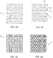
- FIGs. 3a-3g various embodiments of the electrically conducting structure 21 are schematically illustrated in side view.
- Fig. 3a shows a meandering structure with relatively sharp corners (angles of 900), while Fig. 3b shows a similar meandering structure with rounded corners.
- the surfaces 22 22', ...) are arranged substantially in parallel.
- the surfaces 22 are electrically in series, and are connected by respective corner sections.
- Fig. 3c constitutes a rectangular grid.
- the surfaces 22 are not only connected at their sides, but also at various places between these sides. In this way, the electrical current can be distributed over the structure.
- Fig. 3d The embodiment of Fig. 3d is similar to that of Fig. 3c , but constitutes a triangular rather than a rectangular grid.
- a hexagonal grid is illustrated in Fig. 3e , while grids constituted by arrangements of rounded shapes are shown in Figs. 3f and 3g .
- the distance between two successive surfaces 22, 22', in the penetration direction preferably lies between approximately 20 and 5 mm and may advantageously lie between approximately 11 and 9 mm.
- a spacing of about 10 mm between the surfaces results in a time interval between two successive surface penetrations of about 1 ⁇ s. The present inventors have found this time interval to be advantageous for disrupting the jet while maintaining the current through the jet. However, other spacings can also be used, such as spacings larger than 20 mm.
- the thickness of a surface 22 preferably lies between 20 and 5 ⁇ m, and may advantageously lie between 11 and 9 ⁇ m. A thickness of approximately 10 ⁇ m will result in an increased electrical impedance due to heating and/or evaporation, and will thereby assist in commutating the current to the next surface.
- the electrically insulating material (23 in Fig. 1 ), in which the structures are embedded to form arrangements 20, may comprise plastic foam or any other suitable material, for example (hard) plastic.
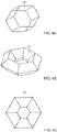
- Fig. 3e already showed a hexagonal structure in plan view, as an embodiment of the electrically conductive structure 21.
- a hexagonal structure is shown in perspective in Fig. 4a and illustrates the type of elementary cell out of which the structure 21 can be made up.
- Another type of elementary cell is illustrated in Fig. 4b , which shows a torus structure in perspective. It will be understood that such torus20 shaped elements can be stacked to form the conductive structure 21.
- a similar structure is shown in plan view in Fig. 4c . These structure can all be embedded in electrically insulating material to form arrangements 20.
- the surfaces of the electrically conductive structure may be constituted by sheets of materials, such as metal foil.
- the surfaces will be electrically interconnected so as to provide a single electrically conductive structure.
- the armour is based upon the insight that electrically conducting surfaces, which are electrically connected and embedded in an electrically insulating material, cause a stepwise shortening of the electrical path of the current through the electrode as it is pierced by the charge. These electrically conducting surfaces constitute a structure which may be supported by the electrically insulating material. The stepwise shortening of the electrical path causes a very effective disruption of the charge.
Description
- The present invention relates to electric reactive armour (ELRA), a system for protecting a vehicle or a vessel containing such an electric reactive armour, a vehicle or a vessel provided with such a system. Furthermore the invention provides a method of protecting a vehicle or a vessel.
- An electric reactive armour, comprises a first electrode and a second electrode spaced apart from the first electrode, to which electrodes a high voltage can be applied so as to disrupt a charge that impacts on the electric reactive armour. Such an armour is known from European Patent
EP 1 877 720 & United States PatentUS 8 006 607 (Fraunhofer-Gesellschaft). - The known armour is designed to protect an object from threats such as shaped charges, for example RPGs (Rocket Propelled Grenades). On impact, the charge of an RPG produces a high speed jet of typically molten metal, which has a high penetrating power. As a high voltage is applied to the electrodes, the jet effectively creates a short circuit when it has penetrated the first electrode and reaches the second electrode. As a result of the short circuit, a strong electrical current will flow through the jet, which gives rise to a magnetic field that in turn gives rise to a Lorentz force on the jet. This disturbs the jet and distorts its needle shape, thus significantly reducing its penetrating power.
-
European Patent EP 1 877 720 mentioned above discloses a second electrode which is made of a spatially heterogeneous material, such as open-pore aluminium foam. The patent states that the electrode material should have a very good electrical conductivity. Using such a spatially heterogeneous electrode material apparently causes electrode material to be displaced in a direction away from the longitudinal axis of the jet, thus increasing the disturbance of the jet. However, it has been found that this disturbance of the jet can be improved upon and that more effective disturbance arrangements are possible.
Bulgarian utility model applicationBG 103643
JP2002295996 EP1877720 discloses an object protection device with an electrode array to which a voltage is applied. The electrode facing the object comprises an area with a metal foam that may have a honeycomb structure. Similarly,WO2010082970 discloses an electromagnetic armor system with a honeycomb structured open-cell lattice core between two conductive layers. - It is an object to overcome these and other problems of the Prior Art and to provide an electric reactive armour which causes a very effective disturbance of the shaped charge jet.
- Accordingly, an electric reactive armour according to
claim 1 and claim 4 is provided. Preferably the electrodes each comprise a metal plate, the metal plates extending in parallel to each other, and the surfaces extend in parallel with the metal plates in a stack of surfaces between the metal plates. In this way the largest number of surfaces can be realized in a distance D between the metal plates, given the distances between successive surfaces. - According to a further aspect, an electric reactive armour is provided, comprising a first metal plate and a second metal plate insulated from the first metal plate. Preferably the second metal plate extends in parallel with the first metal plate. Insulating material is provided between the first and second plate and connectors are provided coupled to the first and second metal plate respectively, for applying an electric voltage between the first and second metal plate. An electrically conductive structure is provided comprising a plurality of layers of electrical conductor material located between the first and second metal plate embedded in the insulating material, the layers of electrical conductor material being electrically coupled to each other and preferably to the second metal plate. The layers of electrical conductor material are arranged such that a charge penetrating the first metal plate will penetrate the layers of electrical conductor material successively. Preferably, the first and second metal plate extend parallel to each other and the layers of electrical conductor material extend in parallel to the first and second metal plate.
By providing an electrically conductive structure having a plurality of surfaces embedded in an insulating material, such that a jet due the charge penetrates successive surfaces of the electrically conductive structure, it is accomplished that the electrical point of contact of the tip of the jet is renewed in a stepwise manner without need to interrupt the current. This stepwise renewal of the point of contact serves to destabilize the jet. It may cause the initially needle-shaped jet to form a series of relatively broad discs. That is, the electrical current caused by the stepwise penetration distorts the jet in such a manner, that it is blunted and effectively fragmented. As a result, the jet will penetrate the second electrode is penetrated over a smaller distance and the jet may be stopped altogether. The more successive surfaces are used, the stronger the effect of destabilization of the jet. - The conductive structure also causes an early onset of the current, which further assists in the distortion of the jet.
- In an embodiment the surfaces are electrically connected in series, configured such that, in case of a short circuit between the first electrode and one of the surfaces that is closest to the first electrode, a short circuit current to said one of the surfaces that is closest to the first electrode flows successively through successive ones of the surfaces that are successively closer to the first electrode. This reduces a delay involved with build up of current when the contact is renewed.
- In an embodiment, the electrically conductive structure comprises a meandering structure. Such a meandering structure preferably has main surfaces which extend substantially parallel to each other, which main surfaces are connected by curved surfaces and/or by surfaces arranged at an angle of, for example, 900 relative to the main surfaces. A meandering structure has the advantage of being simple yet effective.
- In the embodiment wherein the electrically conductive structure comprises a structure of linked cavities, such as a honeycomb structure, each cavity may extend substantially through the width of the structure, or may be small relative to said width, and is on several sides surrounded by conductive surfaces.
- In an advantageous embodiment, the electrically conductive structure comprises a plurality of electrically conductive elements made of conductive foil, such as metal foil. The electrically conductive elements may each constitute a hexagonal cylinder or a hexagonal torus. In such embodiments, the conductive structure may be constituted by stacking three-dimensional elements, such as cylinders. It is noted that other embodiments, such as the meandering conductive structure mentioned above, may also be made of conductive foil.
- In preferred embodiments, the second electrode further comprises a base element on which the electrically conductive structure is mounted and to which it is electrically connected, which base element preferably comprises a solid metal plate. In these embodiments, the second electrode is constituted by both an embedded conductive structure for disrupting the charge, and a metal plate for providing mechanical protection. It will be understood that the embedded conductive structure is mounted in the base element in such a way that the structure faces the jet, so that the jet will reach the structure before it reaches the base element.
- An armour as defined above is provided, further comprising a stripper plate arranged between the first electrode and the second electrode for reducing the width of the charge and/or for providing further mechanical resistance. The stripper plate may, for example, be made of metal, such as armour quality metal.
- A system for protecting a vehicle or a vessel like an armoured boat is provided, the system comprising at least one high voltage source and an electric reactive armour as defined above.
- A vehicle or vessel is provided with a system as defined above.
- A method of protecting a vehicle or a vessel is proviced, the method comprising the step of applying a system as defined above.
- These and other aspects will further be explained below with reference to exemplary embodiments illustrated in the accompanying drawings, in which:
-
Fig. 1 schematically shows an embodiment of an electric reactive armour. -
Fig. 1a shows an armour system for protecting a vehicle or a vessel -
Fig. 2 schematically shows an alternative embodiment of an electric reactive armour, provided with a stripper plate. -
Figs. 3a-3g schematically show various embodiments of the electrically conductive structure. -
Fig. 4a-4c schematically show various embodiments of arrangements of surfaces for use in the electrically conductive structure . - The electric reactive armour (ELRA) 10 shown merely by way of nonlimiting example in
Fig. 1 comprises afirst electrode 1 and asecond electrode 2, which electrodes are spaced apart at a distance (D+d). First andsecond electrode reactive armour 10 comprises an electricallyconductive structure 21, comprising a plurality ofsurfaces 22, i.e. layers of electrical conductor material, located between the first and second metal plate, extending transverse to a direction from the first metal plate to the second metal plate, preferably in parallel to the first and second metal plate The plurality ofsurfaces 22 of the electricallyconductive structure 21 are in electrical contact with the second metal plate, and normally electrically isolated from the first metal plate. Because of this, the electricallyconductive structure 21 may be considered to be part of thesecond electrode 2. As shown, a plurality of electricallyconductive structures 21 may be provided in parallel at different locations on the second metal plate. The figures only show a section of the electric reactive armour wherein one or more of these electricallyconductive structures 21 are present, but it should be appreciated that the electric reactive armour may extend further and more electricallyconductive structures 21 may be present. -
Fig.1a schematically shows an armour system comprsising such an electricreactive armour 10 and anelectrical power source 50 connected between thefirst electrode 1 and thesecond electrode 2. The electricreactive armour 10 may compriseconnectors 52 coupled tofirst electrode 1 and asecond electrode 2 for electrically connectingelectrical power source 50 tofirst electrode 1 and asecond electrode 2.Electrical power source 50 may comprise a capacitor connected betweenfirst electrode 1 and asecond electrode 2. A high electric voltage can be applied to the electrodes using a suitableelectrical power source 50, such as a capacitor. Typical suitable voltages range between 1000 and 5000 V, depending on the application and on the dimensioning of the armour. The power source should be capable of supplying a strong current during a short period of time, for example 100 to 500 kA during 100 µs, or 1000 kA during 50 µs. When the power source comprises a capacitor, the capacitor may be located on the electrode side of theconnectors 52. This reduces power dissipation by the connectors. Again, the current to be supplied will depend on the application and the dimensioning of the armour. - In a typical application, the
first electrode 1 will face away from the object to be protected, such as the interior of a vehicle, a boat, a tank or other vessel, while thesecond electrode 2 will face towards said object. In the embodiment shown inFig. 1 , thefirst electrode 1 is constituted by a metal plate, made of armour quality metal. Thesecond electrode 2 ofFig. 1 also comprises ametal plate 29, which preferably is also made of armour quality metal so as to resist bullets and other projectiles. As shown, the metal plates that form first andsecond electrode - Some projectiles, however, are capable of producing a jet of molten metal upon impact. Such projectiles may be rocket propelled grenades (RPGs), the charge of which typically produces such a jet. Most armour plates are not capable of withstanding such charges, unless the plates are very thick. However, thick armour plates are necessarily heavy, and make it unfeasible to use such thick plates in vehicles, boats and other small vessels. Electric reactive armour (ELRA) is designed to destabilize or disrupt the jet of a charge as it penetrates the armour. The electric reactive armour is designed to disrupt the jet even more.
- As shown in
Fig. 1 , thejet 7 of a charge penetrates thefirst electrode 1. Thesecond electrode 2 comprises a series ofarrangements conductive structure 21 having a plurality ofsurfaces 22 embedded in an insulatingmaterial 23. Thesurfaces 22 need not be designed to resist charges. Instead, thesurfaces 22 are designed to be penetrated by thejet 7. However, a certain resistance to thejet 7 may be desirable in some embodiments. In preferred embodiments, however, thesurfaces 22, 22', ... , and typically theentire structure 21, is made of relatively thin electrically conductive foil. - As shown, the electrically conductive foil forms the
surfaces 22, 22'... (i.e. layers of electrical conductor material) as well as the electrical connections between successive ones of thesurfaces 22, 22'...at the edges of thesurfaces 22, 22'.... Thus, a meandering current path will arise when a short circuit arises between thesurface 22 nearestfirst electrode 1 and thatfirst electrode 1. In successive surfaces (layers) 22, 22'.... the current will flow alternately in opposite directions parallel to the plane of thefirst electrode 1, and towards the first electrode in alternate opposite sides of the surfaces (layers). - The current will flow through a first one of the surfaces in a first direction parallel with the plane of
first electrode 1. Next the current flows in a direction towards that plane to an adjacent second one of the surfaces, at the edge of the surfaces where the foil runs from the first one of the surfaces to the second one of the surfaces. Next the current flows through the second one of the surfaces in a second direction parallel to said plane, but opposite to the first direction. This repeats for successive ones of the layers. Alternatively, the edges of the surfaces may be electrically connected to supply conductors (not shown) that extend from thesecond electrode 2 in the direction of thefirst electrode 1. This has the effect that when a short circuit arises between a surface andfirst electrode 1, time is needed to build up electrical current. Use of a foil that meanders to form the surfaces has the advantage that less time is needed to build up current in successive surfaces once a short circuit has arisen between the surface closest to thefirst electrode 1 and thatfirst electrode 1. More generally, this may be realized by a series connection of thesurfaces 22, configured such that the electrical current flows successively throughsurfaces 22 that are successively closer to thefirst electrode 1. - It is noted that these surfaces (layers) are substantially parallel to the
base plate 29 of thesecond electrode 2. It is further noted that the electricallyconductive structure 21 is both mechanically and electrically connected to the (electrically conducting)base element 29 at connectingpoints 25. Eachsurface 22, 22' forms a layer of electrical conductor material (shown in cross-section), the layer being parallel to first andsecond electrodes - When the jet starts penetrating the electric reactive armour it first penetrates
first electrode 1, then the electrically insulating material and subsequently reaches thefirst surface 22 of the electricallyconductive structure 21. As this electrically conductive structure is electrically connected to thesecond electrode 2, it is electrically connected to thepower source 50 mentioned above. Accordingly, thejet 7 will create a short-circuit between theelectrodes conductive structure 21 and the jet, thus causing a strong electrical current to flow through the jet from thesurface 20 closest to thefirst electrode 1. After some time, the strong current may cause thesurface 20 that is in contact with the jet (i.e. the electrical conductor layer) to evaporate at the contact due to the heat generated by the concentrated current at the contact with the jet. However, until this has happened a strong current flows through the jet. This strong current generates strong electromechanical forces which distort the jet. Initially the distortion is not sufficient to stop the jet from further penetrating thearrangement 20. This further penetration will cause the jet to reach the next surface 22', thus also causing a short-circuit via the next surface. All or at least most of the short circuit current will then flow into the jet through its contact with that next surface 22'. Meanwhile, thefirst surface 22 or at least its contact with the jet will be, or have been, at least partially destroyed by thejet 7. The point of contact between thejet 7 and thesurface 22 is likely to have evaporated (and become a plasma). However, due to the next surface 22' being contacted by thejet 7, thefirst surface 22 is no longer necessary to conduct the current. The current through the jet commutates from the point of contact withsurface 22 to the next point of contact with surface 22'. Thus a substantially continuous flow of current is guaranteed. Meanwhile, the length of the current path through theconductive structure 21 decreases, thus reducing its electrical resistance and thereby increasing the current. - This process of the
jet 7 penetratingsuccessive surfaces 22, 22', ... continues until the jet reaches the metal base of thesecond electrode 2. In typical embodiments, the jet will be disrupted to such an extent by the time that it reaches the second electrode that it is no longer capable of significantly penetrating themetal plate part 29 of thesecond electrode 2. - As can be seen, the
jet 7 of the charge penetrates successive surfaces of the electrically conductive structure, thus producing short-circuits in a stepwise manner. As each successive surface is damaged or destroyed by the jet, the next surface is used to conduct the short-circuit current. In this way, it is assured that the jet disrupting current is present over a relatively long distance. Thus, as a result of using a plurality of layers of electrical conductor material between the first andsecond electrode first electrode 1. Because the destabilizing effect of the current on the jet is strongest at the tip this improves the effect on the jet. The thickness of each surfaces (layer) 22 affects the time needed before the contact of the surface and the jet evaporates. Preferably, the combination of the thickness of surfaces (layers) 22 and their mutual distance is selected so that their contacts with an jet each evaporate in about the time that the tip of an average jet needs to travel the distance to the next surface (e.g. between 50% and 150% of that time). For example a combination of a thickness of about 1 micrometer and a distance of 1 millimeter may be used. The time needed for evaporation may scale with the square of the thickness of the surface (layer) 22, and hence the distance betweensuccessive surfaces 22 may also be scaled with the square of the thickness. An optimized combination may be determined experimentally by trying different thicknesses and measuring time dependence of the current, or by doing so for different distances. - In the embodiment of
Fig. 1 , thearrangements 20, 20', ... have a height D and are separated from thefirst electrode 1 by an optional air gap having a height d. The total distance between the electrodes therefore is equal to (D+d). In case the air gap is omitted, the distance between the electrodes equals the height D of thearrangements 20. When the air gap is present, thefirst electrode 1 and thearrangement 20 are spaced apart by a distance d. When the air gap is not present, thefirst electrode 1 and thearrangement 1 are not spaced apart but are electrically insulating by the top layer of insulatingmaterial 23. It will be understood that in such embodiments this top layer will have to have a sufficient thickness in order to prevent undesired discharges. - The embodiment of
Fig. 2 is essentially identical to the one ofFig. 1 , with the exception of thestripper plate 3. Thisplate 3 is arranged between thefirst electrode 1 and thesecond electrode 2 to reduce the width of thejet 7. In the example ofFig. 2 , thestripper plate 3 is shown to be penetrated by thejet 7. It will be understood that neither thestripper plate 3, nor thefirst electrode 1, will have an opening before being penetrated by thejet 7. - By providing mechanical resistance, the jet is slowed down and is reduced in width, thus mitigating its destructive effect. The
stripper plate 3 is preferably made of armour quality steel or a similar material. - In
Figs. 3a-3g various embodiments of theelectrically conducting structure 21 are schematically illustrated in side view. -
Fig. 3a shows a meandering structure with relatively sharp corners (angles of 900), whileFig. 3b shows a similar meandering structure with rounded corners. In both embodiments, the surfaces 22 (22', ...) are arranged substantially in parallel. In both embodiments, thesurfaces 22 are electrically in series, and are connected by respective corner sections. - The embodiment of
Fig. 3c constitutes a rectangular grid. Thesurfaces 22 are not only connected at their sides, but also at various places between these sides. In this way, the electrical current can be distributed over the structure. - The embodiment of
Fig. 3d is similar to that ofFig. 3c , but constitutes a triangular rather than a rectangular grid. A hexagonal grid is illustrated inFig. 3e , while grids constituted by arrangements of rounded shapes are shown inFigs. 3f and 3g . - In all embodiments, the distance between two
successive surfaces 22, 22', in the penetration direction, preferably lies between approximately 20 and 5 mm and may advantageously lie between approximately 11 and 9 mm. A spacing of about 10 mm between the surfaces results in a time interval between two successive surface penetrations of about 1 µs. The present inventors have found this time interval to be advantageous for disrupting the jet while maintaining the current through the jet. However, other spacings can also be used, such as spacings larger than 20 mm. - The thickness of a
surface 22 preferably lies between 20 and 5 µm, and may advantageously lie between 11 and 9 µm. A thickness of approximately 10 µm will result in an increased electrical impedance due to heating and/or evaporation, and will thereby assist in commutating the current to the next surface. - It is noted that the electrically insulating material (23 in
Fig. 1 ), in which the structures are embedded to formarrangements 20, may comprise plastic foam or any other suitable material, for example (hard) plastic. -
Fig. 3e already showed a hexagonal structure in plan view, as an embodiment of the electricallyconductive structure 21. Such a hexagonal structure is shown in perspective inFig. 4a and illustrates the type of elementary cell out of which thestructure 21 can be made up. Another type of elementary cell is illustrated inFig. 4b , which shows a torus structure in perspective. It will be understood that such torus20 shaped elements can be stacked to form theconductive structure 21. A similar structure is shown in plan view inFig. 4c . These structure can all be embedded in electrically insulating material to formarrangements 20. - The surfaces of the electrically conductive structure may be constituted by sheets of materials, such as metal foil. The surfaces will be electrically interconnected so as to provide a single electrically conductive structure.
- The armour is based upon the insight that electrically conducting surfaces, which are electrically connected and embedded in an electrically insulating material, cause a stepwise shortening of the electrical path of the current through the electrode as it is pierced by the charge. These electrically conducting surfaces constitute a structure which may be supported by the electrically insulating material. The stepwise shortening of the electrical path causes a very effective disruption of the charge.
- It is noted that any terms used in this document should not be construed so as to limit the scope of the present invention. In particular, the words "comprise(s)" and "comprising" are not meant to exclude any elements not specifically stated. Single (circuit) elements may be substituted with multiple (circuit) elements or with their equivalents.
- It will be understood by those skilled in the art that the present invention is not limited to the embodiments illustrated above and that many modifications and additions may be made without departing from the scope of the invention as defined in the appended claims.
Claims (15)
- An electric reactive armour (10), comprising- a first electrode (1) and a second electrode (2) electrically insulated from the first electrode, between which electrodes (1, 2) a high voltage can be applied so as to disrupt a charge (7) contacting the electrodes,
wherein the second electrode (2) comprises- an electrically conductive structure (21) having a plurality of parallel surfaces (22) embedded in an insulating material (23), such that the charge penetrates successive surfaces (22) of the electrically conductive structure,
characterized in that the plurality of parallel surfaces (22) are made of a single conductive foil, said single conductive foil extending successively through successive ones of the parallel surfaces (22), the successive parallel surfaces being located successively closer to the first electrode (1) wherein the successive parallel surfaces are electrically connected in series, so that, in case of a short circuit between the first electrode and one of the parallel surfaces (22) that is closest to the first electrode (1) due to the charge penetrating the successive surfaces of the electrically conductive structures, a short circuit current flows from the first electrode to said one of the surfaces (22) and successively through successive ones of the surfaces (22) that are successively closer to the first electrode (1). - The armour according to claim 1, wherein the electrically conductive structure (21) comprises a meandering structure.
- The armour according to any one of the preceding claims wherein the surfaces (22) are not only connected at their sides, but also at various places between these sides.
- An electric reactive armour (10), comprising- a first electrode (1) and a second electrode (2) electrically insulated from the first electrode, between which electrodes (1, 2) a high voltage can be applied so as to disrupt a charge (7) contacting the electrodes,
wherein the second electrode (2) comprises- an electrically conductive structure (21) located between the first electrode (1) and second electrode (2), the electrically conductive structure (21) comprising a plurality of electrically conductive elements made of electrically conductive foil, such as metal foil, the electrically conductive elements each constituting a hexagonal cylinder or a hexagonal torus, the electrically conductive structure (21) having a plurality of surfaces (22) embedded in an insulating material (23), such that the charge penetrates successive surfaces (22) of the electrically conductive structure, wherein the electrically conductive structure (21) comprises a structure of linked cavities, such as a honeycomb structure. - The armour according to any of the preceding claims, wherein the second electrode (2) further comprises a base element (29) on which the electrically conductive structure (21) is mounted and to which it is electrically connected, which base element (29) preferably comprises a solid metal plate.
- The armour according to any of the preceding claims, wherein the distance between two successive surfaces (22, 22') of said plurality, in the penetration direction, lies between 5 and 20 mm.
- The armour according to any of the preceding claims, wherein the distance between each pair of successive surfaces (22, 22') in said plurality, in the penetration direction, lies between 5 and 20 mm.
- The armour according to any of the preceding claims, wherein the thickness of a surface (22) lies between 5 and 20 µm.
- The armour according to any of the preceding claims, wherein the first electrode (1) is constituted by a solid metal plate.
- The armour according to any of the preceding claims, wherein the first electrode (1) is constituted by a first solid metal plate, and the second electrode (2) comprising a second solid metal plate (29) extending in parallel with the first solid metal plate, the surfaces (22) each extending in parallel with said first and second solid metal plate.
- The armour according to any of the preceding claims, further comprising a stripper plate (3) arranged between the first electrode (1) and the second electrode (2) for reducing the width of the charge.
- An electric reactive armour according to any one of the preceding claims, comprising- a first metal plate forming the first electrode;- a second metal plate forming the second electrode extending in parallel with the first metal plate and electrically insulated from the first metal plate,- the insulating material, located between the first and second plate,- connectors coupled to the first and second metal plate respectively, for applying an electric voltage between the first and second metal plate, and- the surfaces (22) of the electrically conductive structure forming a stack of a plurality of layers of electrical conductor material located between the first and second metal plate, embedded in the insulating material, each of the layers extending in parallel with the first and second metal plate, the layers of electrical conductor material being electrically coupled to the second metal plate.
- A system for protecting a vehicle or vessel, the system comprising at least one high voltage source and an electric reactive armour according to any of the preceding claims.
- A vehicle or vessel provided with a system according to claim 13.
- A method of protecting a vehicle or a vessel, comprising the step of applying a system according to claim 13.
Priority Applications (1)
| Application Number | Priority Date | Filing Date | Title |
|---|---|---|---|
| PL15732971.5T PL3149427T5 (en) | 2014-06-02 | 2015-06-02 | Electric reactive armour |
Applications Claiming Priority (2)
| Application Number | Priority Date | Filing Date | Title |
|---|---|---|---|
| NL2012932A NL2012932B1 (en) | 2014-06-02 | 2014-06-02 | Electric reactive Armour. |
| PCT/NL2015/050396 WO2015187013A1 (en) | 2014-06-02 | 2015-06-02 | Electric reactive armour |
Publications (3)
| Publication Number | Publication Date |
|---|---|
| EP3149427A1 EP3149427A1 (en) | 2017-04-05 |
| EP3149427B1 EP3149427B1 (en) | 2019-04-10 |
| EP3149427B2 true EP3149427B2 (en) | 2022-07-06 |
Family
ID=51230144
Family Applications (1)
| Application Number | Title | Priority Date | Filing Date |
|---|---|---|---|
| EP15732971.5A Active EP3149427B2 (en) | 2014-06-02 | 2015-06-02 | Electric reactive armour |
Country Status (7)
| Country | Link |
|---|---|
| US (1) | US9897418B2 (en) |
| EP (1) | EP3149427B2 (en) |
| KR (1) | KR102345655B1 (en) |
| IL (1) | IL249351B (en) |
| NL (1) | NL2012932B1 (en) |
| PL (1) | PL3149427T5 (en) |
| WO (1) | WO2015187013A1 (en) |
Families Citing this family (2)
| Publication number | Priority date | Publication date | Assignee | Title |
|---|---|---|---|---|
| CN109131805B (en) * | 2018-08-03 | 2019-11-26 | 武汉理工大学 | Battleship based on release and subdivision function protects liquid tank |
| EP4345409A1 (en) | 2022-09-30 | 2024-04-03 | John Cockerill Defense SA | Unmanned turret having a ballistic protection system in the roof structure and in the floor |
Citations (3)
| Publication number | Priority date | Publication date | Assignee | Title |
|---|---|---|---|---|
| DE4244546A1 (en) † | 1992-12-30 | 1998-05-14 | Deutsch Franz Forsch Inst | Electromagnetic sandwich esp for repulsing military attacks such as with missiles |
| SE522191C2 (en) † | 2000-09-13 | 2004-01-20 | Foersvarets Forskningsanstalt | Armored vehicle capable of handling range of different attack kinetic energy projectiles and RSV radiation units and uses electromagnetic armoring comprising two connecting parallel plates with intermediate space |
| US20060196350A1 (en) † | 2005-03-04 | 2006-09-07 | Thierry Bouet | Module structure for electrical armour plating |
Family Cites Families (19)
| Publication number | Priority date | Publication date | Assignee | Title |
|---|---|---|---|---|
| DE3122367C1 (en) | 1981-06-05 | 1994-12-22 | Deutsche Aerospace | Wall for protection against shaped charges and kinetic-energy projectiles |
| DE3515792C1 (en) | 1985-05-02 | 1998-04-30 | Deutsch Franz Forsch Inst | Active armouring with at least one armour plate |
| NL8600449A (en) | 1986-02-22 | 1987-09-16 | Delft Tech Hogeschool | ARMOR PLATE-COMPOSITE WITH CERAMIC COLLECTION COAT. |
| DE4034401A1 (en) | 1990-10-29 | 1992-04-30 | Deutsch Franz Forsch Inst | Electromagnetic armour plating - has two metal plates with dielectric and potential difference between them short-circuited by projectile to produce diverting lorentz force |
| BG566Y1 (en) * | 1999-08-06 | 2002-09-30 | Институт по металознание при БАН | Electric armour |
| JP3643781B2 (en) * | 2001-03-30 | 2005-04-27 | 三菱重工業株式会社 | Aircraft defense device |
| US6601497B2 (en) | 2001-04-24 | 2003-08-05 | The United States Of America As Represented By The Secretary Of The Army | Armor with in-plane confinement of ceramic tiles |
| US7946211B1 (en) * | 2004-04-23 | 2011-05-24 | The United States Of America As Represented By The Secretary Of The Navy | Electrical and elastomeric disruption of high-velocity projectiles |
| WO2006085989A2 (en) | 2004-07-16 | 2006-08-17 | Ensign-Bickford Aerospace & Defense Company | Explosively powered electromagnetic reactive armor |
| US7180302B2 (en) * | 2004-07-16 | 2007-02-20 | Simula, Inc | Method and system for determining cracks and broken components in armor |
| DE102005021348B3 (en) | 2005-05-04 | 2006-12-28 | Fraunhofer-Gesellschaft zur Förderung der angewandten Forschung e.V. | Protection module for the protection of objects with electric current against threats, in particular by shaped charges |
| US7819050B1 (en) | 2005-08-18 | 2010-10-26 | General Atomics | Active armor system |
| US20120017754A1 (en) * | 2006-09-15 | 2012-01-26 | Joynt Vernon P | Armor system and method for defeating high energy projectiles that include metal jets |
| US8151685B2 (en) | 2006-09-15 | 2012-04-10 | Force Protection Industries, Inc. | Apparatus for defeating high energy projectiles |
| US8091464B1 (en) | 2007-10-29 | 2012-01-10 | Raytheon Company | Shaped charge resistant protective shield |
| WO2010082970A2 (en) * | 2008-10-23 | 2010-07-22 | University Of Virginia Patent Foundation | Reactive topologically controlled armors for protection and related method |
| DE102009038630A1 (en) * | 2009-08-26 | 2011-04-28 | Rheinmetall Waffe Munition Gmbh | Protection module for an object against in particular shaped charge projectiles |
| DE102010019475A1 (en) | 2010-05-05 | 2011-11-10 | Fraunhofer-Gesellschaft zur Förderung der angewandten Forschung e.V. | Device for protecting an object at least against shaped charge jets |
| CA2809109A1 (en) * | 2010-08-24 | 2012-03-01 | Batelle Memorial Institute | Ferro electro magnetic armor |
-
2014
- 2014-06-02 NL NL2012932A patent/NL2012932B1/en not_active IP Right Cessation
-
2015
- 2015-06-02 PL PL15732971.5T patent/PL3149427T5/en unknown
- 2015-06-02 KR KR1020167036925A patent/KR102345655B1/en active IP Right Grant
- 2015-06-02 EP EP15732971.5A patent/EP3149427B2/en active Active
- 2015-06-02 WO PCT/NL2015/050396 patent/WO2015187013A1/en active Application Filing
- 2015-06-02 US US15/315,917 patent/US9897418B2/en active Active
-
2016
- 2016-12-01 IL IL249351A patent/IL249351B/en active IP Right Grant
Patent Citations (3)
| Publication number | Priority date | Publication date | Assignee | Title |
|---|---|---|---|---|
| DE4244546A1 (en) † | 1992-12-30 | 1998-05-14 | Deutsch Franz Forsch Inst | Electromagnetic sandwich esp for repulsing military attacks such as with missiles |
| SE522191C2 (en) † | 2000-09-13 | 2004-01-20 | Foersvarets Forskningsanstalt | Armored vehicle capable of handling range of different attack kinetic energy projectiles and RSV radiation units and uses electromagnetic armoring comprising two connecting parallel plates with intermediate space |
| US20060196350A1 (en) † | 2005-03-04 | 2006-09-07 | Thierry Bouet | Module structure for electrical armour plating |
Non-Patent Citations (1)
| Title |
|---|
| German translation of SE 522191 C2 † |
Also Published As
| Publication number | Publication date |
|---|---|
| IL249351B (en) | 2021-04-29 |
| US9897418B2 (en) | 2018-02-20 |
| PL3149427T3 (en) | 2019-10-31 |
| WO2015187013A1 (en) | 2015-12-10 |
| NL2012932B1 (en) | 2016-06-16 |
| KR102345655B1 (en) | 2021-12-31 |
| IL249351A0 (en) | 2017-02-28 |
| KR20170023883A (en) | 2017-03-06 |
| US20170097212A1 (en) | 2017-04-06 |
| EP3149427A1 (en) | 2017-04-05 |
| EP3149427B1 (en) | 2019-04-10 |
| PL3149427T5 (en) | 2022-10-03 |
Similar Documents
| Publication | Publication Date | Title |
|---|---|---|
| EP3149427B1 (en) | Electric reactive armour | |
| US7661350B2 (en) | Module structure for electrical armour plating | |
| CN110383537B (en) | Electricity storage device | |
| WO2014003136A1 (en) | Secondary cell | |
| US10374234B2 (en) | Current collectors for improved safety | |
| KR102001195B1 (en) | battery | |
| JP2013510395A5 (en) | ||
| CN104969320B (en) | Arc-chutes in electrical switchgear for arc extinguishing configure | |
| US9118168B2 (en) | Spark gap configuration for providing overvoltage protection | |
| JP5962280B2 (en) | Electrode manufacturing method | |
| CN114982080B (en) | Electrical switching arrangement | |
| US20070013137A1 (en) | Target device | |
| JP2009066642A (en) | Electromagnetic forming device for thin sheet, and metallic thin sheet for fluid apparatus | |
| KR102046247B1 (en) | Electomagnetic accelerator using the trigered spakr gap | |
| WO2016110505A3 (en) | Device for the extraction of electrical charge carriers from a charge carrier generation space and method for operating such a device | |
| RU2143586C1 (en) | Impulse erosion plasma engine | |
| JP6794736B2 (en) | Power storage device | |
| EA008198B1 (en) | Reactive armouring | |
| CN202102995U (en) | Explosion chamber for a miniature circuit breaker | |
| CN104390523B (en) | The armoring shield of Electromagnetic Control and defence method thereof | |
| Zhang et al. | Measurements of the Characteristics of Plasma Plume Generated by Low Energy Surface Flashover | |
| JP2016091718A (en) | Power storage device and power storage module | |
| CN114340128A (en) | Series SDBD plasma exciter with shielding electrode | |
| CN102832083B (en) | Arc extinguish chamber of miniature circuit breaker | |
| KR101555920B1 (en) | Electric armor and protection system |
Legal Events
| Date | Code | Title | Description |
|---|---|---|---|
| STAA | Information on the status of an ep patent application or granted ep patent |
Free format text: STATUS: THE INTERNATIONAL PUBLICATION HAS BEEN MADE |
|
| PUAI | Public reference made under article 153(3) epc to a published international application that has entered the european phase |
Free format text: ORIGINAL CODE: 0009012 |
|
| STAA | Information on the status of an ep patent application or granted ep patent |
Free format text: STATUS: REQUEST FOR EXAMINATION WAS MADE |
|
| 17P | Request for examination filed |
Effective date: 20161228 |
|
| AK | Designated contracting states |
Kind code of ref document: A1 Designated state(s): AL AT BE BG CH CY CZ DE DK EE ES FI FR GB GR HR HU IE IS IT LI LT LU LV MC MK MT NL NO PL PT RO RS SE SI SK SM TR |
|
| AX | Request for extension of the european patent |
Extension state: BA ME |
|
| DAV | Request for validation of the european patent (deleted) | ||
| DAX | Request for extension of the european patent (deleted) | ||
| STAA | Information on the status of an ep patent application or granted ep patent |
Free format text: STATUS: EXAMINATION IS IN PROGRESS |
|
| 17Q | First examination report despatched |
Effective date: 20180329 |
|
| GRAP | Despatch of communication of intention to grant a patent |
Free format text: ORIGINAL CODE: EPIDOSNIGR1 |
|
| STAA | Information on the status of an ep patent application or granted ep patent |
Free format text: STATUS: GRANT OF PATENT IS INTENDED |
|
| INTG | Intention to grant announced |
Effective date: 20181029 |
|
| RIN1 | Information on inventor provided before grant (corrected) |
Inventor name: DIEDEREN, ANDRE MARCEL Inventor name: HESKES, PETRUS JACOBUS MARIE Inventor name: EVENBLIJ, BEREND HENDRIK Inventor name: HILVERS, FREDERIK JOHANNES Inventor name: VERHORST, FREDERIK M. Inventor name: BORSBOOM, WALTERUS WILHELMUS JOHANNES |
|
| GRAS | Grant fee paid |
Free format text: ORIGINAL CODE: EPIDOSNIGR3 |
|
| GRAA | (expected) grant |
Free format text: ORIGINAL CODE: 0009210 |
|
| STAA | Information on the status of an ep patent application or granted ep patent |
Free format text: STATUS: THE PATENT HAS BEEN GRANTED |
|
| AK | Designated contracting states |
Kind code of ref document: B1 Designated state(s): AL AT BE BG CH CY CZ DE DK EE ES FI FR GB GR HR HU IE IS IT LI LT LU LV MC MK MT NL NO PL PT RO RS SE SI SK SM TR |
|
| REG | Reference to a national code |
Ref country code: GB Ref legal event code: FG4D |
|
| REG | Reference to a national code |
Ref country code: CH Ref legal event code: EP Ref country code: AT Ref legal event code: REF Ref document number: 1119279 Country of ref document: AT Kind code of ref document: T Effective date: 20190415 |
|
| REG | Reference to a national code |
Ref country code: IE Ref legal event code: FG4D |
|
| REG | Reference to a national code |
Ref country code: DE Ref legal event code: R096 Ref document number: 602015028025 Country of ref document: DE |
|
| REG | Reference to a national code |
Ref country code: SE Ref legal event code: TRGR |
|
| REG | Reference to a national code |
Ref country code: NL Ref legal event code: FP |
|
| REG | Reference to a national code |
Ref country code: LT Ref legal event code: MG4D |
|
| REG | Reference to a national code |
Ref country code: NO Ref legal event code: T2 Effective date: 20190410 |
|
| REG | Reference to a national code |
Ref country code: AT Ref legal event code: MK05 Ref document number: 1119279 Country of ref document: AT Kind code of ref document: T Effective date: 20190410 |
|
| PG25 | Lapsed in a contracting state [announced via postgrant information from national office to epo] |
Ref country code: FI Free format text: LAPSE BECAUSE OF FAILURE TO SUBMIT A TRANSLATION OF THE DESCRIPTION OR TO PAY THE FEE WITHIN THE PRESCRIBED TIME-LIMIT Effective date: 20190410 Ref country code: PT Free format text: LAPSE BECAUSE OF FAILURE TO SUBMIT A TRANSLATION OF THE DESCRIPTION OR TO PAY THE FEE WITHIN THE PRESCRIBED TIME-LIMIT Effective date: 20190910 Ref country code: HR Free format text: LAPSE BECAUSE OF FAILURE TO SUBMIT A TRANSLATION OF THE DESCRIPTION OR TO PAY THE FEE WITHIN THE PRESCRIBED TIME-LIMIT Effective date: 20190410 Ref country code: AL Free format text: LAPSE BECAUSE OF FAILURE TO SUBMIT A TRANSLATION OF THE DESCRIPTION OR TO PAY THE FEE WITHIN THE PRESCRIBED TIME-LIMIT Effective date: 20190410 Ref country code: ES Free format text: LAPSE BECAUSE OF FAILURE TO SUBMIT A TRANSLATION OF THE DESCRIPTION OR TO PAY THE FEE WITHIN THE PRESCRIBED TIME-LIMIT Effective date: 20190410 Ref country code: LT Free format text: LAPSE BECAUSE OF FAILURE TO SUBMIT A TRANSLATION OF THE DESCRIPTION OR TO PAY THE FEE WITHIN THE PRESCRIBED TIME-LIMIT Effective date: 20190410 |
|
| PG25 | Lapsed in a contracting state [announced via postgrant information from national office to epo] |
Ref country code: RS Free format text: LAPSE BECAUSE OF FAILURE TO SUBMIT A TRANSLATION OF THE DESCRIPTION OR TO PAY THE FEE WITHIN THE PRESCRIBED TIME-LIMIT Effective date: 20190410 Ref country code: BG Free format text: LAPSE BECAUSE OF FAILURE TO SUBMIT A TRANSLATION OF THE DESCRIPTION OR TO PAY THE FEE WITHIN THE PRESCRIBED TIME-LIMIT Effective date: 20190710 Ref country code: GR Free format text: LAPSE BECAUSE OF FAILURE TO SUBMIT A TRANSLATION OF THE DESCRIPTION OR TO PAY THE FEE WITHIN THE PRESCRIBED TIME-LIMIT Effective date: 20190711 Ref country code: LV Free format text: LAPSE BECAUSE OF FAILURE TO SUBMIT A TRANSLATION OF THE DESCRIPTION OR TO PAY THE FEE WITHIN THE PRESCRIBED TIME-LIMIT Effective date: 20190410 |
|
| PG25 | Lapsed in a contracting state [announced via postgrant information from national office to epo] |
Ref country code: IS Free format text: LAPSE BECAUSE OF FAILURE TO SUBMIT A TRANSLATION OF THE DESCRIPTION OR TO PAY THE FEE WITHIN THE PRESCRIBED TIME-LIMIT Effective date: 20190810 Ref country code: AT Free format text: LAPSE BECAUSE OF FAILURE TO SUBMIT A TRANSLATION OF THE DESCRIPTION OR TO PAY THE FEE WITHIN THE PRESCRIBED TIME-LIMIT Effective date: 20190410 |
|
| REG | Reference to a national code |
Ref country code: DE Ref legal event code: R026 Ref document number: 602015028025 Country of ref document: DE |
|
| PLBI | Opposition filed |
Free format text: ORIGINAL CODE: 0009260 |
|
| PLAX | Notice of opposition and request to file observation + time limit sent |
Free format text: ORIGINAL CODE: EPIDOSNOBS2 |
|
| PG25 | Lapsed in a contracting state [announced via postgrant information from national office to epo] |
Ref country code: CZ Free format text: LAPSE BECAUSE OF FAILURE TO SUBMIT A TRANSLATION OF THE DESCRIPTION OR TO PAY THE FEE WITHIN THE PRESCRIBED TIME-LIMIT Effective date: 20190410 Ref country code: RO Free format text: LAPSE BECAUSE OF FAILURE TO SUBMIT A TRANSLATION OF THE DESCRIPTION OR TO PAY THE FEE WITHIN THE PRESCRIBED TIME-LIMIT Effective date: 20190410 Ref country code: SK Free format text: LAPSE BECAUSE OF FAILURE TO SUBMIT A TRANSLATION OF THE DESCRIPTION OR TO PAY THE FEE WITHIN THE PRESCRIBED TIME-LIMIT Effective date: 20190410 Ref country code: DK Free format text: LAPSE BECAUSE OF FAILURE TO SUBMIT A TRANSLATION OF THE DESCRIPTION OR TO PAY THE FEE WITHIN THE PRESCRIBED TIME-LIMIT Effective date: 20190410 Ref country code: EE Free format text: LAPSE BECAUSE OF FAILURE TO SUBMIT A TRANSLATION OF THE DESCRIPTION OR TO PAY THE FEE WITHIN THE PRESCRIBED TIME-LIMIT Effective date: 20190410 Ref country code: MC Free format text: LAPSE BECAUSE OF FAILURE TO SUBMIT A TRANSLATION OF THE DESCRIPTION OR TO PAY THE FEE WITHIN THE PRESCRIBED TIME-LIMIT Effective date: 20190410 |
|
| REG | Reference to a national code |
Ref country code: CH Ref legal event code: PL |
|
| 26 | Opposition filed |
Opponent name: RHEINMETALL WAFFE MUNITION GMBH Effective date: 20200103 |
|
| PG25 | Lapsed in a contracting state [announced via postgrant information from national office to epo] |
Ref country code: SM Free format text: LAPSE BECAUSE OF FAILURE TO SUBMIT A TRANSLATION OF THE DESCRIPTION OR TO PAY THE FEE WITHIN THE PRESCRIBED TIME-LIMIT Effective date: 20190410 |
|
| PG25 | Lapsed in a contracting state [announced via postgrant information from national office to epo] |
Ref country code: TR Free format text: LAPSE BECAUSE OF FAILURE TO SUBMIT A TRANSLATION OF THE DESCRIPTION OR TO PAY THE FEE WITHIN THE PRESCRIBED TIME-LIMIT Effective date: 20190410 |
|
| PG25 | Lapsed in a contracting state [announced via postgrant information from national office to epo] |
Ref country code: IE Free format text: LAPSE BECAUSE OF NON-PAYMENT OF DUE FEES Effective date: 20190602 |
|
| PG25 | Lapsed in a contracting state [announced via postgrant information from national office to epo] |
Ref country code: LI Free format text: LAPSE BECAUSE OF NON-PAYMENT OF DUE FEES Effective date: 20190630 Ref country code: SI Free format text: LAPSE BECAUSE OF FAILURE TO SUBMIT A TRANSLATION OF THE DESCRIPTION OR TO PAY THE FEE WITHIN THE PRESCRIBED TIME-LIMIT Effective date: 20190410 Ref country code: LU Free format text: LAPSE BECAUSE OF NON-PAYMENT OF DUE FEES Effective date: 20190602 Ref country code: CH Free format text: LAPSE BECAUSE OF NON-PAYMENT OF DUE FEES Effective date: 20190630 |
|
| PLBB | Reply of patent proprietor to notice(s) of opposition received |
Free format text: ORIGINAL CODE: EPIDOSNOBS3 |
|
| PG25 | Lapsed in a contracting state [announced via postgrant information from national office to epo] |
Ref country code: CY Free format text: LAPSE BECAUSE OF FAILURE TO SUBMIT A TRANSLATION OF THE DESCRIPTION OR TO PAY THE FEE WITHIN THE PRESCRIBED TIME-LIMIT Effective date: 20190410 |
|
| PG25 | Lapsed in a contracting state [announced via postgrant information from national office to epo] |
Ref country code: MT Free format text: LAPSE BECAUSE OF FAILURE TO SUBMIT A TRANSLATION OF THE DESCRIPTION OR TO PAY THE FEE WITHIN THE PRESCRIBED TIME-LIMIT Effective date: 20190410 Ref country code: HU Free format text: LAPSE BECAUSE OF FAILURE TO SUBMIT A TRANSLATION OF THE DESCRIPTION OR TO PAY THE FEE WITHIN THE PRESCRIBED TIME-LIMIT; INVALID AB INITIO Effective date: 20150602 |
|
| PLAB | Opposition data, opponent's data or that of the opponent's representative modified |
Free format text: ORIGINAL CODE: 0009299OPPO |
|
| R26 | Opposition filed (corrected) |
Opponent name: RHEINMETALL WAFFE MUNITION GMBH Effective date: 20200103 |
|
| PUAH | Patent maintained in amended form |
Free format text: ORIGINAL CODE: 0009272 |
|
| STAA | Information on the status of an ep patent application or granted ep patent |
Free format text: STATUS: PATENT MAINTAINED AS AMENDED |
|
| PG25 | Lapsed in a contracting state [announced via postgrant information from national office to epo] |
Ref country code: MK Free format text: LAPSE BECAUSE OF FAILURE TO SUBMIT A TRANSLATION OF THE DESCRIPTION OR TO PAY THE FEE WITHIN THE PRESCRIBED TIME-LIMIT Effective date: 20190410 |
|
| 27A | Patent maintained in amended form |
Effective date: 20220706 |
|
| AK | Designated contracting states |
Kind code of ref document: B2 Designated state(s): AL AT BE BG CH CY CZ DE DK EE ES FI FR GB GR HR HU IE IS IT LI LT LU LV MC MK MT NL NO PL PT RO RS SE SI SK SM TR |
|
| REG | Reference to a national code |
Ref country code: DE Ref legal event code: R102 Ref document number: 602015028025 Country of ref document: DE |
|
| REG | Reference to a national code |
Ref country code: NL Ref legal event code: FP |
|
| REG | Reference to a national code |
Ref country code: SE Ref legal event code: RPEO |
|
| REG | Reference to a national code |
Ref country code: NO Ref legal event code: TB2 |
|
| P01 | Opt-out of the competence of the unified patent court (upc) registered |
Effective date: 20230522 |
|
| PGFP | Annual fee paid to national office [announced via postgrant information from national office to epo] |
Ref country code: NO Payment date: 20230622 Year of fee payment: 9 Ref country code: NL Payment date: 20230620 Year of fee payment: 9 Ref country code: FR Payment date: 20230630 Year of fee payment: 9 Ref country code: DE Payment date: 20230620 Year of fee payment: 9 |
|
| PGFP | Annual fee paid to national office [announced via postgrant information from national office to epo] |
Ref country code: SE Payment date: 20230620 Year of fee payment: 9 Ref country code: PL Payment date: 20230522 Year of fee payment: 9 |
|
| PGFP | Annual fee paid to national office [announced via postgrant information from national office to epo] |
Ref country code: BE Payment date: 20230620 Year of fee payment: 9 |
|
| PGFP | Annual fee paid to national office [announced via postgrant information from national office to epo] |
Ref country code: IT Payment date: 20230623 Year of fee payment: 9 Ref country code: GB Payment date: 20230622 Year of fee payment: 9 |
|
| PGFP | Annual fee paid to national office [announced via postgrant information from national office to epo] |
Ref country code: FR Payment date: 20230721 Year of fee payment: 9 |