EP3148884B1 - Vorrichtung und verfahren zum gesteuerten ausrichten und/oder drehen von behältern - Google Patents
Vorrichtung und verfahren zum gesteuerten ausrichten und/oder drehen von behältern Download PDFInfo
- Publication number
- EP3148884B1 EP3148884B1 EP15722715.8A EP15722715A EP3148884B1 EP 3148884 B1 EP3148884 B1 EP 3148884B1 EP 15722715 A EP15722715 A EP 15722715A EP 3148884 B1 EP3148884 B1 EP 3148884B1
- Authority
- EP
- European Patent Office
- Prior art keywords
- container
- container holders
- orientation
- containers
- group
- Prior art date
- Legal status (The legal status is an assumption and is not a legal conclusion. Google has not performed a legal analysis and makes no representation as to the accuracy of the status listed.)
- Active
Links
Images


Classifications
-
- B—PERFORMING OPERATIONS; TRANSPORTING
- B65—CONVEYING; PACKING; STORING; HANDLING THIN OR FILAMENTARY MATERIAL
- B65B—MACHINES, APPARATUS OR DEVICES FOR, OR METHODS OF, PACKAGING ARTICLES OR MATERIALS; UNPACKING
- B65B17/00—Other machines, apparatus, or methods for packaging articles or materials
- B65B17/02—Joining articles, e.g. cans, directly to each other for convenience of storage, transport, or handling
-
- B—PERFORMING OPERATIONS; TRANSPORTING
- B65—CONVEYING; PACKING; STORING; HANDLING THIN OR FILAMENTARY MATERIAL
- B65C—LABELLING OR TAGGING MACHINES, APPARATUS, OR PROCESSES
- B65C9/00—Details of labelling machines or apparatus
- B65C9/02—Devices for moving articles, e.g. containers, past labelling station
- B65C9/04—Devices for moving articles, e.g. containers, past labelling station having means for rotating the articles
-
- B—PERFORMING OPERATIONS; TRANSPORTING
- B65—CONVEYING; PACKING; STORING; HANDLING THIN OR FILAMENTARY MATERIAL
- B65B—MACHINES, APPARATUS OR DEVICES FOR, OR METHODS OF, PACKAGING ARTICLES OR MATERIALS; UNPACKING
- B65B21/00—Packaging or unpacking of bottles
-
- B—PERFORMING OPERATIONS; TRANSPORTING
- B65—CONVEYING; PACKING; STORING; HANDLING THIN OR FILAMENTARY MATERIAL
- B65B—MACHINES, APPARATUS OR DEVICES FOR, OR METHODS OF, PACKAGING ARTICLES OR MATERIALS; UNPACKING
- B65B35/00—Supplying, feeding, arranging or orientating articles to be packaged
- B65B35/10—Feeding, e.g. conveying, single articles
- B65B35/26—Feeding, e.g. conveying, single articles by rotary conveyors
-
- B—PERFORMING OPERATIONS; TRANSPORTING
- B65—CONVEYING; PACKING; STORING; HANDLING THIN OR FILAMENTARY MATERIAL
- B65B—MACHINES, APPARATUS OR DEVICES FOR, OR METHODS OF, PACKAGING ARTICLES OR MATERIALS; UNPACKING
- B65B35/00—Supplying, feeding, arranging or orientating articles to be packaged
- B65B35/56—Orientating, i.e. changing the attitude of, articles, e.g. of non-uniform cross-section
- B65B35/58—Turning articles by positively-acting means, e.g. to present labelled portions in uppermost position
-
- B—PERFORMING OPERATIONS; TRANSPORTING
- B65—CONVEYING; PACKING; STORING; HANDLING THIN OR FILAMENTARY MATERIAL
- B65C—LABELLING OR TAGGING MACHINES, APPARATUS, OR PROCESSES
- B65C9/00—Details of labelling machines or apparatus
- B65C9/06—Devices for presenting articles in predetermined attitude or position at labelling station
- B65C9/067—Devices for presenting articles in predetermined attitude or position at labelling station for orienting articles having irregularities, e.g. holes, spots or markings, e.g. labels or imprints, the irregularities or markings being detected
-
- B—PERFORMING OPERATIONS; TRANSPORTING
- B65—CONVEYING; PACKING; STORING; HANDLING THIN OR FILAMENTARY MATERIAL
- B65G—TRANSPORT OR STORAGE DEVICES, e.g. CONVEYORS FOR LOADING OR TIPPING, SHOP CONVEYOR SYSTEMS OR PNEUMATIC TUBE CONVEYORS
- B65G47/00—Article or material-handling devices associated with conveyors; Methods employing such devices
- B65G47/22—Devices influencing the relative position or the attitude of articles during transit by conveyors
- B65G47/24—Devices influencing the relative position or the attitude of articles during transit by conveyors orientating the articles
- B65G47/244—Devices influencing the relative position or the attitude of articles during transit by conveyors orientating the articles by turning them about an axis substantially perpendicular to the conveying plane
-
- B—PERFORMING OPERATIONS; TRANSPORTING
- B65—CONVEYING; PACKING; STORING; HANDLING THIN OR FILAMENTARY MATERIAL
- B65G—TRANSPORT OR STORAGE DEVICES, e.g. CONVEYORS FOR LOADING OR TIPPING, SHOP CONVEYOR SYSTEMS OR PNEUMATIC TUBE CONVEYORS
- B65G47/00—Article or material-handling devices associated with conveyors; Methods employing such devices
- B65G47/74—Feeding, transfer, or discharging devices of particular kinds or types
- B65G47/80—Turntables carrying articles or materials to be transferred, e.g. combined with ploughs or scrapers
-
- B—PERFORMING OPERATIONS; TRANSPORTING
- B65—CONVEYING; PACKING; STORING; HANDLING THIN OR FILAMENTARY MATERIAL
- B65G—TRANSPORT OR STORAGE DEVICES, e.g. CONVEYORS FOR LOADING OR TIPPING, SHOP CONVEYOR SYSTEMS OR PNEUMATIC TUBE CONVEYORS
- B65G2201/00—Indexing codes relating to handling devices, e.g. conveyors, characterised by the type of product or load being conveyed or handled
- B65G2201/02—Articles
- B65G2201/0235—Containers
- B65G2201/0244—Bottles
Definitions
- the invention relates to a device for the controlled alignment and / or rotation of containers according to the preamble of claim 1 and in particular to a device with the container between a container inlet and a container outlet on an alignment section of a transport and Ausrichtumble in a desired orientation at least once be aligned, by controlled turning or pivoting about its container axis.
- the alignment section extends over the entire transport and Ausrichtumble or is at least a portion of the transport and Ausrichtiety.
- the invention relates to a method for the controlled alignment and / or controlled turning of containers.
- the controlled rotational movement of the individual container receptacles is especially when these container receptacles are individually rotated preferably generated by each container receptacle is assigned its own controllable rotary drive with its own electric actuator or servomotor. Alone the multitude of rotary actuators means a considerable design effort.
- a device for aligning containers ( DE 30 22 343 C2 ) with a circumferentially driven about a vertical axis transport star, which is formed at its periphery with a plurality of container receptacles.
- These consist in each case of a container transport pocket which is open on the circumference and with a container system leading and trailing in relation to the direction of rotation of the transport star against which the respective container rests with its peripheral surface and which is formed by a section of an alignment belt or band.
- This is driven as a closed loop endlessly circulating, by a rotary drive with servo or servo motor, which is provided as well as the Ausrichtriemen for each container recording independently. Alone the multitude of rotary actuators in turn means a considerable design effort.
- the object of the invention is to provide a device for controlled alignment and / or turning of containers, which allows for reduced design complexity and a plurality of container receptacles on a transport element, at least those container receptacles, each located on the alignment section of the between the container inlet and the container outlet extending transport and Ausrichtumble are individually, ie independently controlled for the alignment and / or rotation of the container to rotate their container axis individually.
- a device for the controlled alignment and rotation of containers according to the patent claim 1 is formed.
- One Method for controlled alignment and / or rotation of containers is designed according to claim 11.
- the particular advantage of the device according to the invention is that despite the large number of rotationally controlled container receptacles only a reduced number of controllable rotary actuators is necessary, for a group of container receptacles only a single controllable rotary drive with servo or servo motor, and yet for the container recordings of different groups at least on an alignment section of the transport and Ausrichtrich a controlled individual rotation is possible. That is, each container receptacle of a group moving (container receptacle) along the alignment portion can rotate independently of the container receptacles of the other groups there.
- the electrical actuating or servomotors of the rotary drives can be provided stationarily on a machine frame, i. it is not necessary that these servomotors or servomotors are moved with the container receptacles having transport element. This eliminates the need for electrical connections via sliding contacts for the control and / or supply of servomotors or servomotors.
- each group of container receptacles rotary drive includes, for example, a belt, chain or belt drive, which connects all container receptacles of the respective group with one of this group associated actuator or servo motor drivingly.
- the belt itself to form contact surfaces for the containers or their lateral surface arranged in or on the container receptacles.
- the container receptacles of each group of container receptacles are drivingly connected via a gear transmission with the associated actuator or servomotor.
- Rotatable container receptacles are in the context of the invention quite generally recordings, in or at which the containers are arranged during transport between the container inlet and the container outlet and for a controlled rotational movement of the container about its container axis, preferably about its vertical or substantially vertical container axis are formed.
- rotationally controlled container receptacles include turntable on which the containers stand up with their container bottom, gripper and container carrier, including those for a suspended support of the container, and container transport pockets, the container bearing surfaces for controlled rotation of the container rotating or running around, for example at least a circumferentially drivable Ausrichtriemen or -band are formed.
- “Alignment of the containers” in the sense of the invention means that the containers are rotated about their container axis controlled so that they then have a desired orientation, for example with respect to a container feature or with respect to an applied to the respective container element such. Label, imprint, glue application, etc ..
- Container are in the context of the invention in particular cans, bottles, tubes, Pourches, each made of metal, glass and / or plastic, but also other packaging, which are suitable for filling products, especially liquid or viscous.
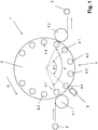
- the device generally designated 1 in the figures is used for at least one-time alignment, controlled turning and transporting containers 2 on an orientation or alignment section 5.1 of an alignment and transport path 5 in such a way that they have a desired orientation after alignment or are rotated on the alignment section 5.1 by a desired angular amount, this angle of rotation in the orientation of container 2 to container 2 may be different, depending on the orientation that the respective container 2 had at the inlet into the alignment section 5.1 randomly.
- the device 1 includes i.a. a container conveyor, which is in the illustrated embodiment of a driven around a vertical machine axis MA circumferentially (arrow A) on the rotor 3 is formed.
- a container conveyor which is in the illustrated embodiment of a driven around a vertical machine axis MA circumferentially (arrow A) on the rotor 3 is formed.
- container receptacles 4.1 - 4.4 are provided successively in the direction of rotation or transport A, namely at a uniform angular or pitch spacing around the machine axis MA.
- the container receptacles 4.1 - 4.4 which are shown for ease of presentation as a turntable on which the container 2 stand up with its container bottom, form a plurality of groups of container receptacles, i.
- each group having a plurality of container receptacles associated with that group, i. a first group a plurality of container receptacles 4.1, a second group a plurality of container receptacles 4.2, a third group a plurality of container receptacles 4.3 and a fourth group a plurality of container receptacles 4.4.
- the number of container receptacles 4.1 - 4.4 is identical in the groups and is for example four.
- the arrangement of the container receptacles is further made such that in the direction of rotation or transport A respectively on a container receptacle 4.1 a container receptacle 4.2 on this a container receptacle 4.3, this followed by a container receptacle 4.4 and then again a container receptacle 4.1.
- the container receptacles 4.1 - 4.4 thus form several sequences 4 of container receptacles, each sequence 4 having a container receptacle of each group.
- the at least one-time alignment and controlled rotation of the container 2 is controlled by Turning the respective container receptacle 4.1 - 4.4 about its vertical axis BA, for example, controlled by the signal of at least one Sensor 6, for example, detects the current orientation or rotational position of the respective container receptacle 4.1 - 4.4 and / or the respective container 2.
- the sensor 6 can be any suitable means which makes it possible to detect a container 2 in the necessary manner.
- the sensor is an electronic digital camera with a downstream computer-assisted image processing system.
- Each container 2 then has a desired orientation after alignment and / or has been rotated from its original orientation by a desired angular amount about its vertical container axis.
- the length that the alignment section 5.1 has in the transport direction A is equal to the corresponding length of a sequence 4 or the sum of the pitches between the container receptacles 4.1 - 4.4 of a sequence 4.
- a peculiarity of the device 1 is that for each container receptacles 4.1 - 4.4 each group of container receptacles only a single rotary drive is required with the controlled rotation of only the container receptacles 4.1 - 4.4 of the respective group takes place about the axes BA.
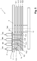
- each group of container receptacles rotary drive is according to the Figures 2-4 realized by a drive unit 7, which, inter alia, for each group an endlessly rotating and a self-contained loop forming toothed belt 8.1 - 8.4 has.
- the timing belts 8.1 - 8.4 or their loops are in different directions the machine axis MA arranged against staggered planes.
- Each toothed belt 8.1 - 8.4 is on a separate for each group of container receptacles and arranged coaxially with the machine axis MA, the timing belt 8.1 - 8.4 driving pulley 9.1 - 9.4, not shown deflection wheels and also driven toothed belt 10.1 - 10.4 out.
- the latter are provided on rotatably mounted in the rotor 3 shafts 11, which are each aligned coaxially with an axis BA and carry a container receptacle 4.1 - 4.4.
- the central toothed belt 9.1 - 9.4 are each provided on shafts 12, which are preferably arranged coaxially with the machine axis MA arranged partially as hollow shafts concentrically surrounding each other and rotatably mounted to each other.
- Each shaft 12 has, in addition to its central toothed belt 9.1 - 9.4 another as a gear or toothed belt 9.1a - 9.4a trained wheel, which is driven by the unrepresented individual servo or servo motor of the respective group of container receptacles.
- the rotor 3 is rotatably mounted on a machine frame 13.
- rotor drive is provided, which then drives the rotor 3, for example, via a central, coaxially arranged with the machine axis MA shaft.
- the shafts 12 designed as hollow shafts are then arranged on this shaft.
- FIG. 5 shows in a presentation like FIG. 3 a drive unit 7a, which can be used instead of the drive unit 7 and has a gear transmission.
- Achs Eisen with the machine axis MA and in several offset in the direction of the machine axis MA levels sprockets 14.1 - 14.2 are provided, which are each individually rotatable by its own servo or servo motor to the machine axis MA.
- Each sprocket 14.1-14.4 is assigned to a group of container receptacles.
- the container receptacles 4.1 - 4.4 of each group are connected via gears 15.1 - 15.4 with the corresponding ring gear 14.1 - 14.4, so again with a single provided for each group servomotor or all container receptacles 4.1 - 4.4 Group for aligning and controlled turning of the container receptacles 4.1 - 4.4 and the container 2 on the alignment section 5.1 are rotated under control.
- the particular advantage of the device 1 is, inter alia, that the required number of servomotors or servomotors is significantly reduced, ie, for example, in a total of sixteen container receptacles 4.1 -4.4, which form four groups, only four servo or servo motors are required.
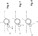
- the device 1 as part of a labeling machine 16 for applying labels in each case to a predetermined and the sensor unit 6 detected area of the container 2 (FIG. FIG. 6 ) using a labeling unit 16.1 used.
- the device 1 can also be used as part of an assembly 17 for aligning (already) equipped containers 2 and for subsequent transfer of the aligned containers 2 to a subsequent machine, for example to a machine for forming containers from a plurality of containers 2 (FIG. FIG. 7 ) be used.
- the device 1 can also be used as part of an assembly 18 for aligning containers 2 with a polygonal cross-section, for example with a square or rectangular cross-section and for passing the aligned containers to a subsequent machine, for example to a machine for forming containers from a plurality of containers 2 ( FIG. 8 ) be used.
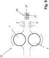
- the device 1 as part of a system 19 for the production of containers 20, each consisting of a plurality of adhesive jobs 21 interconnected containers 2, as also in the FIG. 10 is shown used.
- the system 19 at least one device 1, in the illustrated embodiment, but two devices 1, in which the container 2 by aligning and / or controlled rotation while passing the alignment section 5.1 at the required peripheral areas with adhesive applications 21 are provided, ie in the illustrated containers 20 at peripheral regions which are offset by the respective container axis by 90 ° to each other.
- the application of the adhesive jobs 21 takes place on or else immediately after the alignment section 5.1.
- the container receptacles are possible, for example in the form of container carriers for a suspended support of the container 2 (eg Neckhalter) or in the form of container transport pockets, the container bearing surfaces for controlled rotation of the container rotating or running around, for example, of at least one circumferential drivable Ausrichtriemen or -band are formed, for example, from the belt 8.1 - 8.4 or similar belt.
- the rotationally controlled container receptacles 4.1 - 4.4 are provided on the rotating rotor 3.
- the containers 2 can also be moved on a conveyor belt by the alignment and transport path or by their alignment section, in which case the rotationally driven container receptacles consist of alignment strips arranged next to and / or above the conveyor belt.
Landscapes
- Engineering & Computer Science (AREA)
- Mechanical Engineering (AREA)
- Labeling Devices (AREA)
- Specific Conveyance Elements (AREA)
- Attitude Control For Articles On Conveyors (AREA)
- Special Conveying (AREA)
- Branching, Merging, And Special Transfer Between Conveyors (AREA)
Priority Applications (1)
| Application Number | Priority Date | Filing Date | Title |
|---|---|---|---|
| PL15722715T PL3148884T3 (pl) | 2014-05-27 | 2015-05-13 | Urządzenie i sposób sterowanego ustawiania i/lub obracania pojemników |
Applications Claiming Priority (2)
| Application Number | Priority Date | Filing Date | Title |
|---|---|---|---|
| DE102014107427.0A DE102014107427B4 (de) | 2014-05-27 | 2014-05-27 | Vorrichtung und Verfahren zum gesteuerten Ausrichten und/oder gesteuerten Drehen von Behältern |
| PCT/EP2015/060554 WO2015180959A1 (de) | 2014-05-27 | 2015-05-13 | Vorrichtung und verfahren zum gesteuerten ausrichten und/oder gesteuerten drehen von behältern |
Publications (2)
| Publication Number | Publication Date |
|---|---|
| EP3148884A1 EP3148884A1 (de) | 2017-04-05 |
| EP3148884B1 true EP3148884B1 (de) | 2018-04-04 |
Family
ID=53180736
Family Applications (1)
| Application Number | Title | Priority Date | Filing Date |
|---|---|---|---|
| EP15722715.8A Active EP3148884B1 (de) | 2014-05-27 | 2015-05-13 | Vorrichtung und verfahren zum gesteuerten ausrichten und/oder drehen von behältern |
Country Status (8)
| Country | Link |
|---|---|
| US (1) | US10035620B2 (enExample) |
| EP (1) | EP3148884B1 (enExample) |
| JP (1) | JP6580072B2 (enExample) |
| CN (1) | CN106414246B (enExample) |
| DE (1) | DE102014107427B4 (enExample) |
| ES (1) | ES2666093T3 (enExample) |
| PL (1) | PL3148884T3 (enExample) |
| WO (1) | WO2015180959A1 (enExample) |
Families Citing this family (10)
| Publication number | Priority date | Publication date | Assignee | Title |
|---|---|---|---|---|
| DE102015219937A1 (de) * | 2015-10-14 | 2017-04-20 | Krones Aktiengesellschaft | Behandlungsmaschine für Behälter |
| DE102016007344A1 (de) | 2016-06-17 | 2017-12-21 | Knapp Systemintegration Gmbh | Verfahren zum Kommissionieren von Waren sowie Vorrichtung hierzu |
| JP6725795B2 (ja) * | 2016-12-16 | 2020-07-22 | キリンテクノシステム株式会社 | 搬送装置 |
| EP3388373A1 (de) * | 2017-04-12 | 2018-10-17 | Ferrum AG | Transportmodul zum transport eines behälters, sowie verarbeitungsvorrichtung und verfahren zum transport eines behälters |
| DE102017119084A1 (de) | 2017-08-21 | 2019-02-21 | Beckhoff Automation Gmbh | System und Verfahren zum Ausrichten eines Objekts |
| AU2018337813B2 (en) * | 2017-09-19 | 2021-05-13 | Ball Corporation | Container decoration apparatus and method |
| US10793367B1 (en) * | 2020-01-21 | 2020-10-06 | Transnorm System Gmbh | Conveying table and module |
| LU101702B1 (en) * | 2020-03-25 | 2021-09-27 | Fuji Seal Int Inc | Conveying system and method of conveying a plurality of products |
| EP3943428A1 (en) * | 2020-07-24 | 2022-01-26 | WestRock Packaging Systems, LLC | Orientation module |
| CA3225936A1 (en) | 2021-07-15 | 2023-01-19 | Larry D. Mckinney | Servo-controlled machine line |
Family Cites Families (17)
| Publication number | Priority date | Publication date | Assignee | Title |
|---|---|---|---|---|
| DE2623818C3 (de) | 1976-05-28 | 1980-09-04 | Jagenberg-Werke Ag, 4000 Duesseldorf | Drehteller für eine Etikettiermaschine |
| DE3022343C2 (de) | 1980-06-14 | 1983-10-20 | Kronseder, Hermann, 8404 Wörth | Vorrichtung zum Ausrichten von Flaschen o.dgl., insbesondere in Etikettiermaschinen |
| DE3100197C2 (de) * | 1981-01-07 | 1982-11-04 | Jagenberg-Werke AG, 4000 Düsseldorf | Drehtisch mit Drehtellern für Flaschen in einer Flaschenbehandlungsmaschine, insbesondere Etikettiermaschine |
| US5192392A (en) * | 1991-02-28 | 1993-03-09 | The Bottling Room, Inc. | Container labeler |
| JPH06247534A (ja) * | 1993-02-26 | 1994-09-06 | Fuji Seal Kogyo Kk | ワーク表示部の位置合わせ装置 |
| US5478422A (en) * | 1993-09-16 | 1995-12-26 | B & H Manufacturing Company, Inc. | Computer controlled turret type labeling machine |
| US5858143A (en) * | 1993-09-16 | 1999-01-12 | B & H Manufacturing, Inc. | Computer controlled labeling machine for applying labels including stretch labels and tactilely sensible indicia on articles |
| IT1318020B1 (it) * | 2000-06-13 | 2003-07-21 | Sasib Labelling Machinery S P | Macchina di etichettaggio rotativa automatica |
| US6398006B1 (en) * | 2000-08-29 | 2002-06-04 | Joseph E. Seagram & Sons Ltd. | Rotary turret with pedestals and a method of controlling rotation thereof |
| ITMN20010027A1 (it) * | 2001-06-06 | 2002-12-06 | Pe Srl | Macchina etichettatrice per bottiglie |
| JP3785342B2 (ja) * | 2001-09-28 | 2006-06-14 | 日立エンジニアリング株式会社 | 被検体検査装置及び透明容器の充填液体中の異物検査装置 |
| CN2556167Y (zh) * | 2002-05-27 | 2003-06-18 | 程进村 | 回转式物品收纳构造 |
| ITPR20020049A1 (it) * | 2002-08-27 | 2004-02-28 | Simonazzi S P A Gia Sig Simonazzi Spa | Procedimento per formare etichette tubolari in film termoretraibile e macchina per formare etichette ed inserire bottiglie o contenitori in genere all'interno delle etichette formate. |
| ITMN20030036A1 (it) * | 2003-08-08 | 2005-02-09 | Global Packaging Solutions S R L | Macchina etichettatrice |
| DE102009005181A1 (de) * | 2009-01-15 | 2010-07-29 | Khs Ag | Behälterbehandlungsmaschine |
| CN203411065U (zh) * | 2013-08-08 | 2014-01-29 | 金鼎邦工业股份有限公司 | 旋转带料机构 |
| DE102014100496B4 (de) * | 2014-01-17 | 2016-05-12 | Khs Gmbh | Behälterbehandlungsmaschine sowie Verfahren zum Behandeln von Behältern |
-
2014
- 2014-05-27 DE DE102014107427.0A patent/DE102014107427B4/de active Active
-
2015
- 2015-05-13 US US15/314,193 patent/US10035620B2/en active Active
- 2015-05-13 PL PL15722715T patent/PL3148884T3/pl unknown
- 2015-05-13 EP EP15722715.8A patent/EP3148884B1/de active Active
- 2015-05-13 WO PCT/EP2015/060554 patent/WO2015180959A1/de not_active Ceased
- 2015-05-13 CN CN201580027142.XA patent/CN106414246B/zh active Active
- 2015-05-13 JP JP2016567815A patent/JP6580072B2/ja active Active
- 2015-05-13 ES ES15722715.8T patent/ES2666093T3/es active Active
Also Published As
| Publication number | Publication date |
|---|---|
| US20170190455A1 (en) | 2017-07-06 |
| CN106414246B (zh) | 2018-10-19 |
| JP6580072B2 (ja) | 2019-09-25 |
| EP3148884A1 (de) | 2017-04-05 |
| PL3148884T3 (pl) | 2018-08-31 |
| US10035620B2 (en) | 2018-07-31 |
| JP2017523947A (ja) | 2017-08-24 |
| DE102014107427A1 (de) | 2015-12-03 |
| DE102014107427B4 (de) | 2018-04-26 |
| WO2015180959A1 (de) | 2015-12-03 |
| CN106414246A (zh) | 2017-02-15 |
| ES2666093T3 (es) | 2018-05-03 |
Similar Documents
| Publication | Publication Date | Title |
|---|---|---|
| EP3148884B1 (de) | Vorrichtung und verfahren zum gesteuerten ausrichten und/oder drehen von behältern | |
| EP3006352B1 (de) | Vorrichtung zur bildung von verpackungseinheiten | |
| EP1992579B1 (de) | Vorrichtung zum Verschieben von Gebinden gegenüber einer Transportbahn | |
| DE602004007335T2 (de) | Verfahren und Vorrichtung zum Bilden von Gruppen von Gegenständen und Einstellen des Abstands zwischen den Gruppen | |
| DE69800402T2 (de) | Vorrichtung zum Gruppieren von Gegenständen und Separieren dieser Gruppen von einander, und gegenseitig, zum Zwecke ihrer Verpackung | |
| EP3573910B1 (de) | Behälterbehandlungsanlage und verfahren zum transport von funktionselementen in einer behälterbehandlungsanlage zum behandeln von behältern | |
| EP3071497B1 (de) | Transporteur für behälter | |
| EP1205388B1 (de) | Vorrichtung zur Steuerung der Drehbewegung von Gefässen | |
| EP3768619B1 (de) | Endlos umlaufende behälter-fördervorrichtung in einer verpackungsmaschine | |
| EP2809595A1 (de) | Ovale behälterbehandlungsvorrichtung | |
| EP2817229A1 (de) | Verfahren zum etikettieren von behältern sowie etikettiermaschine | |
| EP1633663B1 (de) | Vorrichtung zum kontinuierlichen befüllen und verschliessen einseitig offener karton/kunststoff-verbundpackungen und zellenkäfig zum transport solcher packungen in der vorrichtung | |
| EP3530598B1 (de) | Antriebssystem für eine behältertransportstrecke sowie behältertransportstrecke mit einem solchen antriebssystem | |
| EP2949581A1 (de) | Verpackungsanlage | |
| EP3099580B1 (de) | Verfahren und vorrichtung zur bildung von verpackungseinheiten | |
| DE102015103654A1 (de) | Etikettiervorrichtung für Behälter | |
| EP3323745B1 (de) | Behälterbehandlungsmaschine und verfahren zur behandlung von behältern | |
| EP0912398B1 (de) | Verfahren und vorrichtung zum transportieren und gruppieren von scheibenförmigen produkten, insbesondere biskuits | |
| CH640189A5 (de) | Anlage mit einem umlaufenden karussell zur behandlung von gegenstaenden sowie verwendung der anlage. | |
| DD228230A5 (de) | Maschine zum verpacken und gruppieren von produkten | |
| EP1846299B1 (de) | Vorrichtung und verfahren zum applizieren von ausgiesselementen auf karton/kunststoff-verbundpackungen und/oder zum verschliessen solcher packungen mittels ultraschall-schweisswerkzeugen | |
| DE1811269C3 (de) | Fördervorrichtung für Behälter | |
| DE2123986A1 (de) | Vorrichtung zum Einsetzen von Verpackungsgegenständen in Behälter | |
| DE3140004A1 (de) | "etikettiereinrichtung" | |
| DE202017105314U1 (de) | Etikettieraggregat mit verbessertem Antrieb |
Legal Events
| Date | Code | Title | Description |
|---|---|---|---|
| PUAI | Public reference made under article 153(3) epc to a published international application that has entered the european phase |
Free format text: ORIGINAL CODE: 0009012 |
|
| 17P | Request for examination filed |
Effective date: 20170102 |
|
| AK | Designated contracting states |
Kind code of ref document: A1 Designated state(s): AL AT BE BG CH CY CZ DE DK EE ES FI FR GB GR HR HU IE IS IT LI LT LU LV MC MK MT NL NO PL PT RO RS SE SI SK SM TR |
|
| AX | Request for extension of the european patent |
Extension state: BA ME |
|
| DAV | Request for validation of the european patent (deleted) | ||
| DAX | Request for extension of the european patent (deleted) | ||
| GRAP | Despatch of communication of intention to grant a patent |
Free format text: ORIGINAL CODE: EPIDOSNIGR1 |
|
| RIC1 | Information provided on ipc code assigned before grant |
Ipc: B65C 9/06 20060101ALI20171129BHEP Ipc: B65B 21/00 20060101ALI20171129BHEP Ipc: B65G 47/80 20060101ALI20171129BHEP Ipc: B65G 47/244 20060101ALI20171129BHEP Ipc: B65B 17/02 20060101ALI20171129BHEP Ipc: B65C 9/04 20060101AFI20171129BHEP Ipc: B65B 35/26 20060101ALI20171129BHEP |
|
| INTG | Intention to grant announced |
Effective date: 20171220 |
|
| GRAS | Grant fee paid |
Free format text: ORIGINAL CODE: EPIDOSNIGR3 |
|
| GRAA | (expected) grant |
Free format text: ORIGINAL CODE: 0009210 |
|
| AK | Designated contracting states |
Kind code of ref document: B1 Designated state(s): AL AT BE BG CH CY CZ DE DK EE ES FI FR GB GR HR HU IE IS IT LI LT LU LV MC MK MT NL NO PL PT RO RS SE SI SK SM TR |
|
| REG | Reference to a national code |
Ref country code: GB Ref legal event code: FG4D Free format text: NOT ENGLISH |
|
| REG | Reference to a national code |
Ref country code: CH Ref legal event code: EP |
|
| REG | Reference to a national code |
Ref country code: AT Ref legal event code: REF Ref document number: 985339 Country of ref document: AT Kind code of ref document: T Effective date: 20180415 |
|
| REG | Reference to a national code |
Ref country code: IE Ref legal event code: FG4D Free format text: LANGUAGE OF EP DOCUMENT: GERMAN |
|
| REG | Reference to a national code |
Ref country code: ES Ref legal event code: FG2A Ref document number: 2666093 Country of ref document: ES Kind code of ref document: T3 Effective date: 20180503 Ref country code: DE Ref legal event code: R096 Ref document number: 502015003760 Country of ref document: DE |
|
| REG | Reference to a national code |
Ref country code: FR Ref legal event code: PLFP Year of fee payment: 4 |
|
| REG | Reference to a national code |
Ref country code: NL Ref legal event code: MP Effective date: 20180404 |
|
| REG | Reference to a national code |
Ref country code: LT Ref legal event code: MG4D |
|
| PG25 | Lapsed in a contracting state [announced via postgrant information from national office to epo] |
Ref country code: NL Free format text: LAPSE BECAUSE OF FAILURE TO SUBMIT A TRANSLATION OF THE DESCRIPTION OR TO PAY THE FEE WITHIN THE PRESCRIBED TIME-LIMIT Effective date: 20180404 |
|
| PG25 | Lapsed in a contracting state [announced via postgrant information from national office to epo] |
Ref country code: NO Free format text: LAPSE BECAUSE OF FAILURE TO SUBMIT A TRANSLATION OF THE DESCRIPTION OR TO PAY THE FEE WITHIN THE PRESCRIBED TIME-LIMIT Effective date: 20180704 Ref country code: AL Free format text: LAPSE BECAUSE OF FAILURE TO SUBMIT A TRANSLATION OF THE DESCRIPTION OR TO PAY THE FEE WITHIN THE PRESCRIBED TIME-LIMIT Effective date: 20180404 Ref country code: FI Free format text: LAPSE BECAUSE OF FAILURE TO SUBMIT A TRANSLATION OF THE DESCRIPTION OR TO PAY THE FEE WITHIN THE PRESCRIBED TIME-LIMIT Effective date: 20180404 Ref country code: BG Free format text: LAPSE BECAUSE OF FAILURE TO SUBMIT A TRANSLATION OF THE DESCRIPTION OR TO PAY THE FEE WITHIN THE PRESCRIBED TIME-LIMIT Effective date: 20180704 Ref country code: SE Free format text: LAPSE BECAUSE OF FAILURE TO SUBMIT A TRANSLATION OF THE DESCRIPTION OR TO PAY THE FEE WITHIN THE PRESCRIBED TIME-LIMIT Effective date: 20180404 Ref country code: LT Free format text: LAPSE BECAUSE OF FAILURE TO SUBMIT A TRANSLATION OF THE DESCRIPTION OR TO PAY THE FEE WITHIN THE PRESCRIBED TIME-LIMIT Effective date: 20180404 |
|
| PG25 | Lapsed in a contracting state [announced via postgrant information from national office to epo] |
Ref country code: RS Free format text: LAPSE BECAUSE OF FAILURE TO SUBMIT A TRANSLATION OF THE DESCRIPTION OR TO PAY THE FEE WITHIN THE PRESCRIBED TIME-LIMIT Effective date: 20180404 Ref country code: HR Free format text: LAPSE BECAUSE OF FAILURE TO SUBMIT A TRANSLATION OF THE DESCRIPTION OR TO PAY THE FEE WITHIN THE PRESCRIBED TIME-LIMIT Effective date: 20180404 Ref country code: LV Free format text: LAPSE BECAUSE OF FAILURE TO SUBMIT A TRANSLATION OF THE DESCRIPTION OR TO PAY THE FEE WITHIN THE PRESCRIBED TIME-LIMIT Effective date: 20180404 Ref country code: GR Free format text: LAPSE BECAUSE OF FAILURE TO SUBMIT A TRANSLATION OF THE DESCRIPTION OR TO PAY THE FEE WITHIN THE PRESCRIBED TIME-LIMIT Effective date: 20180705 |
|
| REG | Reference to a national code |
Ref country code: CH Ref legal event code: PL |
|
| PG25 | Lapsed in a contracting state [announced via postgrant information from national office to epo] |
Ref country code: PT Free format text: LAPSE BECAUSE OF FAILURE TO SUBMIT A TRANSLATION OF THE DESCRIPTION OR TO PAY THE FEE WITHIN THE PRESCRIBED TIME-LIMIT Effective date: 20180806 |
|
| REG | Reference to a national code |
Ref country code: DE Ref legal event code: R097 Ref document number: 502015003760 Country of ref document: DE |
|
| REG | Reference to a national code |
Ref country code: BE Ref legal event code: MM Effective date: 20180531 |
|
| PG25 | Lapsed in a contracting state [announced via postgrant information from national office to epo] |
Ref country code: EE Free format text: LAPSE BECAUSE OF FAILURE TO SUBMIT A TRANSLATION OF THE DESCRIPTION OR TO PAY THE FEE WITHIN THE PRESCRIBED TIME-LIMIT Effective date: 20180404 Ref country code: RO Free format text: LAPSE BECAUSE OF FAILURE TO SUBMIT A TRANSLATION OF THE DESCRIPTION OR TO PAY THE FEE WITHIN THE PRESCRIBED TIME-LIMIT Effective date: 20180404 Ref country code: CZ Free format text: LAPSE BECAUSE OF FAILURE TO SUBMIT A TRANSLATION OF THE DESCRIPTION OR TO PAY THE FEE WITHIN THE PRESCRIBED TIME-LIMIT Effective date: 20180404 Ref country code: MC Free format text: LAPSE BECAUSE OF FAILURE TO SUBMIT A TRANSLATION OF THE DESCRIPTION OR TO PAY THE FEE WITHIN THE PRESCRIBED TIME-LIMIT Effective date: 20180404 Ref country code: DK Free format text: LAPSE BECAUSE OF FAILURE TO SUBMIT A TRANSLATION OF THE DESCRIPTION OR TO PAY THE FEE WITHIN THE PRESCRIBED TIME-LIMIT Effective date: 20180404 Ref country code: SK Free format text: LAPSE BECAUSE OF FAILURE TO SUBMIT A TRANSLATION OF THE DESCRIPTION OR TO PAY THE FEE WITHIN THE PRESCRIBED TIME-LIMIT Effective date: 20180404 |
|
| PLBE | No opposition filed within time limit |
Free format text: ORIGINAL CODE: 0009261 |
|
| STAA | Information on the status of an ep patent application or granted ep patent |
Free format text: STATUS: NO OPPOSITION FILED WITHIN TIME LIMIT |
|
| REG | Reference to a national code |
Ref country code: IE Ref legal event code: MM4A |
|
| PG25 | Lapsed in a contracting state [announced via postgrant information from national office to epo] |
Ref country code: SM Free format text: LAPSE BECAUSE OF FAILURE TO SUBMIT A TRANSLATION OF THE DESCRIPTION OR TO PAY THE FEE WITHIN THE PRESCRIBED TIME-LIMIT Effective date: 20180404 Ref country code: CH Free format text: LAPSE BECAUSE OF NON-PAYMENT OF DUE FEES Effective date: 20180531 Ref country code: LI Free format text: LAPSE BECAUSE OF NON-PAYMENT OF DUE FEES Effective date: 20180531 |
|
| 26N | No opposition filed |
Effective date: 20190107 |
|
| PG25 | Lapsed in a contracting state [announced via postgrant information from national office to epo] |
Ref country code: LU Free format text: LAPSE BECAUSE OF NON-PAYMENT OF DUE FEES Effective date: 20180513 |
|
| PG25 | Lapsed in a contracting state [announced via postgrant information from national office to epo] |
Ref country code: IE Free format text: LAPSE BECAUSE OF NON-PAYMENT OF DUE FEES Effective date: 20180513 |
|
| PG25 | Lapsed in a contracting state [announced via postgrant information from national office to epo] |
Ref country code: SI Free format text: LAPSE BECAUSE OF FAILURE TO SUBMIT A TRANSLATION OF THE DESCRIPTION OR TO PAY THE FEE WITHIN THE PRESCRIBED TIME-LIMIT Effective date: 20180404 Ref country code: BE Free format text: LAPSE BECAUSE OF NON-PAYMENT OF DUE FEES Effective date: 20180531 |
|
| PG25 | Lapsed in a contracting state [announced via postgrant information from national office to epo] |
Ref country code: MT Free format text: LAPSE BECAUSE OF FAILURE TO SUBMIT A TRANSLATION OF THE DESCRIPTION OR TO PAY THE FEE WITHIN THE PRESCRIBED TIME-LIMIT Effective date: 20180404 |
|
| PG25 | Lapsed in a contracting state [announced via postgrant information from national office to epo] |
Ref country code: TR Free format text: LAPSE BECAUSE OF FAILURE TO SUBMIT A TRANSLATION OF THE DESCRIPTION OR TO PAY THE FEE WITHIN THE PRESCRIBED TIME-LIMIT Effective date: 20180404 |
|
| PG25 | Lapsed in a contracting state [announced via postgrant information from national office to epo] |
Ref country code: HU Free format text: LAPSE BECAUSE OF FAILURE TO SUBMIT A TRANSLATION OF THE DESCRIPTION OR TO PAY THE FEE WITHIN THE PRESCRIBED TIME-LIMIT; INVALID AB INITIO Effective date: 20150513 Ref country code: CY Free format text: LAPSE BECAUSE OF FAILURE TO SUBMIT A TRANSLATION OF THE DESCRIPTION OR TO PAY THE FEE WITHIN THE PRESCRIBED TIME-LIMIT Effective date: 20180404 Ref country code: MK Free format text: LAPSE BECAUSE OF NON-PAYMENT OF DUE FEES Effective date: 20180404 |
|
| PG25 | Lapsed in a contracting state [announced via postgrant information from national office to epo] |
Ref country code: IS Free format text: LAPSE BECAUSE OF FAILURE TO SUBMIT A TRANSLATION OF THE DESCRIPTION OR TO PAY THE FEE WITHIN THE PRESCRIBED TIME-LIMIT Effective date: 20180804 |
|
| REG | Reference to a national code |
Ref country code: AT Ref legal event code: MM01 Ref document number: 985339 Country of ref document: AT Kind code of ref document: T Effective date: 20200513 |
|
| PG25 | Lapsed in a contracting state [announced via postgrant information from national office to epo] |
Ref country code: AT Free format text: LAPSE BECAUSE OF NON-PAYMENT OF DUE FEES Effective date: 20200513 |
|
| PGFP | Annual fee paid to national office [announced via postgrant information from national office to epo] |
Ref country code: PL Payment date: 20250505 Year of fee payment: 11 Ref country code: DE Payment date: 20250521 Year of fee payment: 11 |
|
| PGFP | Annual fee paid to national office [announced via postgrant information from national office to epo] |
Ref country code: GB Payment date: 20250521 Year of fee payment: 11 Ref country code: ES Payment date: 20250627 Year of fee payment: 11 |
|
| PGFP | Annual fee paid to national office [announced via postgrant information from national office to epo] |
Ref country code: IT Payment date: 20250527 Year of fee payment: 11 |
|
| PGFP | Annual fee paid to national office [announced via postgrant information from national office to epo] |
Ref country code: FR Payment date: 20250528 Year of fee payment: 11 |
|
| P01 | Opt-out of the competence of the unified patent court (upc) registered |
Free format text: CASE NUMBER: UPC_APP_0014574_3148884/2025 Effective date: 20251125 |