EP3148418B1 - Ferndiagnose von atemtherapievorrichtungen - Google Patents
Ferndiagnose von atemtherapievorrichtungen Download PDFInfo
- Publication number
- EP3148418B1 EP3148418B1 EP15800058.8A EP15800058A EP3148418B1 EP 3148418 B1 EP3148418 B1 EP 3148418B1 EP 15800058 A EP15800058 A EP 15800058A EP 3148418 B1 EP3148418 B1 EP 3148418B1
- Authority
- EP
- European Patent Office
- Prior art keywords
- patient
- diagnostic data
- fault
- data
- respiratory therapy
- Prior art date
- Legal status (The legal status is an assumption and is not a legal conclusion. Google has not performed a legal analysis and makes no representation as to the accuracy of the status listed.)
- Active
Links
Images


Classifications
-
- A—HUMAN NECESSITIES
- A61—MEDICAL OR VETERINARY SCIENCE; HYGIENE
- A61M—DEVICES FOR INTRODUCING MEDIA INTO, OR ONTO, THE BODY; DEVICES FOR TRANSDUCING BODY MEDIA OR FOR TAKING MEDIA FROM THE BODY; DEVICES FOR PRODUCING OR ENDING SLEEP OR STUPOR
- A61M16/00—Devices for influencing the respiratory system of patients by gas treatment, e.g. mouth-to-mouth respiration; Tracheal tubes
- A61M16/0051—Devices for influencing the respiratory system of patients by gas treatment, e.g. mouth-to-mouth respiration; Tracheal tubes with alarm devices
-
- A—HUMAN NECESSITIES
- A61—MEDICAL OR VETERINARY SCIENCE; HYGIENE
- A61B—DIAGNOSIS; SURGERY; IDENTIFICATION
- A61B5/00—Measuring for diagnostic purposes; Identification of persons
- A61B5/08—Detecting, measuring or recording devices for evaluating the respiratory organs
- A61B5/0826—Detecting or evaluating apnoea events
-
- A—HUMAN NECESSITIES
- A61—MEDICAL OR VETERINARY SCIENCE; HYGIENE
- A61M—DEVICES FOR INTRODUCING MEDIA INTO, OR ONTO, THE BODY; DEVICES FOR TRANSDUCING BODY MEDIA OR FOR TAKING MEDIA FROM THE BODY; DEVICES FOR PRODUCING OR ENDING SLEEP OR STUPOR
- A61M16/00—Devices for influencing the respiratory system of patients by gas treatment, e.g. mouth-to-mouth respiration; Tracheal tubes
- A61M16/0057—Pumps therefor
- A61M16/0066—Blowers or centrifugal pumps
- A61M16/0069—Blowers or centrifugal pumps the speed thereof being controlled by respiratory parameters, e.g. by inhalation
-
- A—HUMAN NECESSITIES
- A61—MEDICAL OR VETERINARY SCIENCE; HYGIENE
- A61M—DEVICES FOR INTRODUCING MEDIA INTO, OR ONTO, THE BODY; DEVICES FOR TRANSDUCING BODY MEDIA OR FOR TAKING MEDIA FROM THE BODY; DEVICES FOR PRODUCING OR ENDING SLEEP OR STUPOR
- A61M16/00—Devices for influencing the respiratory system of patients by gas treatment, e.g. mouth-to-mouth respiration; Tracheal tubes
- A61M16/021—Devices for influencing the respiratory system of patients by gas treatment, e.g. mouth-to-mouth respiration; Tracheal tubes operated by electrical means
- A61M16/022—Control means therefor
- A61M16/024—Control means therefor including calculation means, e.g. using a processor
-
- A—HUMAN NECESSITIES
- A61—MEDICAL OR VETERINARY SCIENCE; HYGIENE
- A61M—DEVICES FOR INTRODUCING MEDIA INTO, OR ONTO, THE BODY; DEVICES FOR TRANSDUCING BODY MEDIA OR FOR TAKING MEDIA FROM THE BODY; DEVICES FOR PRODUCING OR ENDING SLEEP OR STUPOR
- A61M16/00—Devices for influencing the respiratory system of patients by gas treatment, e.g. mouth-to-mouth respiration; Tracheal tubes
- A61M16/06—Respiratory or anaesthetic masks
-
- A—HUMAN NECESSITIES
- A61—MEDICAL OR VETERINARY SCIENCE; HYGIENE
- A61M—DEVICES FOR INTRODUCING MEDIA INTO, OR ONTO, THE BODY; DEVICES FOR TRANSDUCING BODY MEDIA OR FOR TAKING MEDIA FROM THE BODY; DEVICES FOR PRODUCING OR ENDING SLEEP OR STUPOR
- A61M16/00—Devices for influencing the respiratory system of patients by gas treatment, e.g. mouth-to-mouth respiration; Tracheal tubes
- A61M16/10—Preparation of respiratory gases or vapours
- A61M16/1075—Preparation of respiratory gases or vapours by influencing the temperature
- A61M16/109—Preparation of respiratory gases or vapours by influencing the temperature the humidifying liquid or the beneficial agent
-
- A—HUMAN NECESSITIES
- A61—MEDICAL OR VETERINARY SCIENCE; HYGIENE
- A61M—DEVICES FOR INTRODUCING MEDIA INTO, OR ONTO, THE BODY; DEVICES FOR TRANSDUCING BODY MEDIA OR FOR TAKING MEDIA FROM THE BODY; DEVICES FOR PRODUCING OR ENDING SLEEP OR STUPOR
- A61M16/00—Devices for influencing the respiratory system of patients by gas treatment, e.g. mouth-to-mouth respiration; Tracheal tubes
- A61M16/10—Preparation of respiratory gases or vapours
- A61M16/14—Preparation of respiratory gases or vapours by mixing different fluids, one of them being in a liquid phase
- A61M16/16—Devices to humidify the respiration air
- A61M16/161—Devices to humidify the respiration air with means for measuring the humidity
-
- G—PHYSICS
- G06—COMPUTING; CALCULATING OR COUNTING
- G06F—ELECTRIC DIGITAL DATA PROCESSING
- G06F11/00—Error detection; Error correction; Monitoring
- G06F11/07—Responding to the occurrence of a fault, e.g. fault tolerance
-
- G—PHYSICS
- G16—INFORMATION AND COMMUNICATION TECHNOLOGY [ICT] SPECIALLY ADAPTED FOR SPECIFIC APPLICATION FIELDS
- G16H—HEALTHCARE INFORMATICS, i.e. INFORMATION AND COMMUNICATION TECHNOLOGY [ICT] SPECIALLY ADAPTED FOR THE HANDLING OR PROCESSING OF MEDICAL OR HEALTHCARE DATA
- G16H20/00—ICT specially adapted for therapies or health-improving plans, e.g. for handling prescriptions, for steering therapy or for monitoring patient compliance
- G16H20/40—ICT specially adapted for therapies or health-improving plans, e.g. for handling prescriptions, for steering therapy or for monitoring patient compliance relating to mechanical, radiation or invasive therapies, e.g. surgery, laser therapy, dialysis or acupuncture
-
- G—PHYSICS
- G16—INFORMATION AND COMMUNICATION TECHNOLOGY [ICT] SPECIALLY ADAPTED FOR SPECIFIC APPLICATION FIELDS
- G16H—HEALTHCARE INFORMATICS, i.e. INFORMATION AND COMMUNICATION TECHNOLOGY [ICT] SPECIALLY ADAPTED FOR THE HANDLING OR PROCESSING OF MEDICAL OR HEALTHCARE DATA
- G16H40/00—ICT specially adapted for the management or administration of healthcare resources or facilities; ICT specially adapted for the management or operation of medical equipment or devices
- G16H40/40—ICT specially adapted for the management or administration of healthcare resources or facilities; ICT specially adapted for the management or operation of medical equipment or devices for the management of medical equipment or devices, e.g. scheduling maintenance or upgrades
-
- G—PHYSICS
- G16—INFORMATION AND COMMUNICATION TECHNOLOGY [ICT] SPECIALLY ADAPTED FOR SPECIFIC APPLICATION FIELDS
- G16H—HEALTHCARE INFORMATICS, i.e. INFORMATION AND COMMUNICATION TECHNOLOGY [ICT] SPECIALLY ADAPTED FOR THE HANDLING OR PROCESSING OF MEDICAL OR HEALTHCARE DATA
- G16H40/00—ICT specially adapted for the management or administration of healthcare resources or facilities; ICT specially adapted for the management or operation of medical equipment or devices
- G16H40/60—ICT specially adapted for the management or administration of healthcare resources or facilities; ICT specially adapted for the management or operation of medical equipment or devices for the operation of medical equipment or devices
- G16H40/67—ICT specially adapted for the management or administration of healthcare resources or facilities; ICT specially adapted for the management or operation of medical equipment or devices for the operation of medical equipment or devices for remote operation
-
- A—HUMAN NECESSITIES
- A61—MEDICAL OR VETERINARY SCIENCE; HYGIENE
- A61B—DIAGNOSIS; SURGERY; IDENTIFICATION
- A61B5/00—Measuring for diagnostic purposes; Identification of persons
- A61B5/08—Detecting, measuring or recording devices for evaluating the respiratory organs
- A61B5/087—Measuring breath flow
-
- A—HUMAN NECESSITIES
- A61—MEDICAL OR VETERINARY SCIENCE; HYGIENE
- A61M—DEVICES FOR INTRODUCING MEDIA INTO, OR ONTO, THE BODY; DEVICES FOR TRANSDUCING BODY MEDIA OR FOR TAKING MEDIA FROM THE BODY; DEVICES FOR PRODUCING OR ENDING SLEEP OR STUPOR
- A61M16/00—Devices for influencing the respiratory system of patients by gas treatment, e.g. mouth-to-mouth respiration; Tracheal tubes
- A61M16/0057—Pumps therefor
- A61M16/0066—Blowers or centrifugal pumps
-
- A—HUMAN NECESSITIES
- A61—MEDICAL OR VETERINARY SCIENCE; HYGIENE
- A61M—DEVICES FOR INTRODUCING MEDIA INTO, OR ONTO, THE BODY; DEVICES FOR TRANSDUCING BODY MEDIA OR FOR TAKING MEDIA FROM THE BODY; DEVICES FOR PRODUCING OR ENDING SLEEP OR STUPOR
- A61M16/00—Devices for influencing the respiratory system of patients by gas treatment, e.g. mouth-to-mouth respiration; Tracheal tubes
- A61M16/10—Preparation of respiratory gases or vapours
- A61M16/105—Filters
- A61M16/1055—Filters bacterial
-
- A—HUMAN NECESSITIES
- A61—MEDICAL OR VETERINARY SCIENCE; HYGIENE
- A61M—DEVICES FOR INTRODUCING MEDIA INTO, OR ONTO, THE BODY; DEVICES FOR TRANSDUCING BODY MEDIA OR FOR TAKING MEDIA FROM THE BODY; DEVICES FOR PRODUCING OR ENDING SLEEP OR STUPOR
- A61M16/00—Devices for influencing the respiratory system of patients by gas treatment, e.g. mouth-to-mouth respiration; Tracheal tubes
- A61M16/10—Preparation of respiratory gases or vapours
- A61M16/105—Filters
- A61M16/106—Filters in a path
- A61M16/107—Filters in a path in the inspiratory path
-
- A—HUMAN NECESSITIES
- A61—MEDICAL OR VETERINARY SCIENCE; HYGIENE
- A61M—DEVICES FOR INTRODUCING MEDIA INTO, OR ONTO, THE BODY; DEVICES FOR TRANSDUCING BODY MEDIA OR FOR TAKING MEDIA FROM THE BODY; DEVICES FOR PRODUCING OR ENDING SLEEP OR STUPOR
- A61M16/00—Devices for influencing the respiratory system of patients by gas treatment, e.g. mouth-to-mouth respiration; Tracheal tubes
- A61M16/10—Preparation of respiratory gases or vapours
- A61M16/14—Preparation of respiratory gases or vapours by mixing different fluids, one of them being in a liquid phase
- A61M16/16—Devices to humidify the respiration air
-
- A—HUMAN NECESSITIES
- A61—MEDICAL OR VETERINARY SCIENCE; HYGIENE
- A61M—DEVICES FOR INTRODUCING MEDIA INTO, OR ONTO, THE BODY; DEVICES FOR TRANSDUCING BODY MEDIA OR FOR TAKING MEDIA FROM THE BODY; DEVICES FOR PRODUCING OR ENDING SLEEP OR STUPOR
- A61M16/00—Devices for influencing the respiratory system of patients by gas treatment, e.g. mouth-to-mouth respiration; Tracheal tubes
- A61M16/0003—Accessories therefor, e.g. sensors, vibrators, negative pressure
- A61M2016/0027—Accessories therefor, e.g. sensors, vibrators, negative pressure pressure meter
-
- A—HUMAN NECESSITIES
- A61—MEDICAL OR VETERINARY SCIENCE; HYGIENE
- A61M—DEVICES FOR INTRODUCING MEDIA INTO, OR ONTO, THE BODY; DEVICES FOR TRANSDUCING BODY MEDIA OR FOR TAKING MEDIA FROM THE BODY; DEVICES FOR PRODUCING OR ENDING SLEEP OR STUPOR
- A61M2205/00—General characteristics of the apparatus
- A61M2205/14—Detection of the presence or absence of a tube, a connector or a container in an apparatus
-
- A—HUMAN NECESSITIES
- A61—MEDICAL OR VETERINARY SCIENCE; HYGIENE
- A61M—DEVICES FOR INTRODUCING MEDIA INTO, OR ONTO, THE BODY; DEVICES FOR TRANSDUCING BODY MEDIA OR FOR TAKING MEDIA FROM THE BODY; DEVICES FOR PRODUCING OR ENDING SLEEP OR STUPOR
- A61M2205/00—General characteristics of the apparatus
- A61M2205/15—Detection of leaks
-
- A—HUMAN NECESSITIES
- A61—MEDICAL OR VETERINARY SCIENCE; HYGIENE
- A61M—DEVICES FOR INTRODUCING MEDIA INTO, OR ONTO, THE BODY; DEVICES FOR TRANSDUCING BODY MEDIA OR FOR TAKING MEDIA FROM THE BODY; DEVICES FOR PRODUCING OR ENDING SLEEP OR STUPOR
- A61M2205/00—General characteristics of the apparatus
- A61M2205/33—Controlling, regulating or measuring
- A61M2205/3368—Temperature
-
- A—HUMAN NECESSITIES
- A61—MEDICAL OR VETERINARY SCIENCE; HYGIENE
- A61M—DEVICES FOR INTRODUCING MEDIA INTO, OR ONTO, THE BODY; DEVICES FOR TRANSDUCING BODY MEDIA OR FOR TAKING MEDIA FROM THE BODY; DEVICES FOR PRODUCING OR ENDING SLEEP OR STUPOR
- A61M2205/00—General characteristics of the apparatus
- A61M2205/35—Communication
- A61M2205/3576—Communication with non implanted data transmission devices, e.g. using external transmitter or receiver
- A61M2205/3584—Communication with non implanted data transmission devices, e.g. using external transmitter or receiver using modem, internet or bluetooth
-
- A—HUMAN NECESSITIES
- A61—MEDICAL OR VETERINARY SCIENCE; HYGIENE
- A61M—DEVICES FOR INTRODUCING MEDIA INTO, OR ONTO, THE BODY; DEVICES FOR TRANSDUCING BODY MEDIA OR FOR TAKING MEDIA FROM THE BODY; DEVICES FOR PRODUCING OR ENDING SLEEP OR STUPOR
- A61M2205/00—General characteristics of the apparatus
- A61M2205/35—Communication
- A61M2205/3576—Communication with non implanted data transmission devices, e.g. using external transmitter or receiver
- A61M2205/3592—Communication with non implanted data transmission devices, e.g. using external transmitter or receiver using telemetric means, e.g. radio or optical transmission
-
- A—HUMAN NECESSITIES
- A61—MEDICAL OR VETERINARY SCIENCE; HYGIENE
- A61M—DEVICES FOR INTRODUCING MEDIA INTO, OR ONTO, THE BODY; DEVICES FOR TRANSDUCING BODY MEDIA OR FOR TAKING MEDIA FROM THE BODY; DEVICES FOR PRODUCING OR ENDING SLEEP OR STUPOR
- A61M2205/00—General characteristics of the apparatus
- A61M2205/42—Reducing noise
-
- A—HUMAN NECESSITIES
- A61—MEDICAL OR VETERINARY SCIENCE; HYGIENE
- A61M—DEVICES FOR INTRODUCING MEDIA INTO, OR ONTO, THE BODY; DEVICES FOR TRANSDUCING BODY MEDIA OR FOR TAKING MEDIA FROM THE BODY; DEVICES FOR PRODUCING OR ENDING SLEEP OR STUPOR
- A61M2205/00—General characteristics of the apparatus
- A61M2205/50—General characteristics of the apparatus with microprocessors or computers
- A61M2205/502—User interfaces, e.g. screens or keyboards
- A61M2205/505—Touch-screens; Virtual keyboard or keypads; Virtual buttons; Soft keys; Mouse touches
-
- A—HUMAN NECESSITIES
- A61—MEDICAL OR VETERINARY SCIENCE; HYGIENE
- A61M—DEVICES FOR INTRODUCING MEDIA INTO, OR ONTO, THE BODY; DEVICES FOR TRANSDUCING BODY MEDIA OR FOR TAKING MEDIA FROM THE BODY; DEVICES FOR PRODUCING OR ENDING SLEEP OR STUPOR
- A61M2205/00—General characteristics of the apparatus
- A61M2205/60—General characteristics of the apparatus with identification means
-
- A—HUMAN NECESSITIES
- A61—MEDICAL OR VETERINARY SCIENCE; HYGIENE
- A61M—DEVICES FOR INTRODUCING MEDIA INTO, OR ONTO, THE BODY; DEVICES FOR TRANSDUCING BODY MEDIA OR FOR TAKING MEDIA FROM THE BODY; DEVICES FOR PRODUCING OR ENDING SLEEP OR STUPOR
- A61M2209/00—Ancillary equipment
- A61M2209/08—Supports for equipment
-
- Y—GENERAL TAGGING OF NEW TECHNOLOGICAL DEVELOPMENTS; GENERAL TAGGING OF CROSS-SECTIONAL TECHNOLOGIES SPANNING OVER SEVERAL SECTIONS OF THE IPC; TECHNICAL SUBJECTS COVERED BY FORMER USPC CROSS-REFERENCE ART COLLECTIONS [XRACs] AND DIGESTS
- Y02—TECHNOLOGIES OR APPLICATIONS FOR MITIGATION OR ADAPTATION AGAINST CLIMATE CHANGE
- Y02A—TECHNOLOGIES FOR ADAPTATION TO CLIMATE CHANGE
- Y02A90/00—Technologies having an indirect contribution to adaptation to climate change
- Y02A90/10—Information and communication technologies [ICT] supporting adaptation to climate change, e.g. for weather forecasting or climate simulation
Definitions
- the present technology relates to medical devices that may be used in connection with the detection, diagnosis, treatment, prevention and amelioration of respiratory-related disorders.
- the respiratory system of the body facilitates gas exchange.
- the nose and mouth form the entrance to the airways of a patient.
- the airways include a series of branching tubes, which become narrower, shorter and more numerous as they penetrate deeper into the lung.
- the prime function of the lung is gas exchange, allowing oxygen to move from the air into the venous blood and carbon dioxide to move out.
- the trachea divides into right and left main bronchi, which further divide eventually into terminal bronchioles.
- the bronchi make up the conducting airways, and do not take part in gas exchange. Further divisions of the airways lead to the respiratory bronchioles, and eventually to the alveoli.
- the alveolated region of the lung is where the gas exchange takes place, and is referred to as the respiratory zone. See " Respiratory Physiology", by John B. West, Lippincott Williams & Wilkins, 9th edition published 2011 .
- Some examples of respiratory disorders include: Obstructive Sleep Apnea (OSA), Cheyne Stokes Respiration (CSR), Obesity Hyperventilation Syndrome (OHS), Chronic Obstructive Pulmonary Disease (COPD), Neuromuscular Disease (NMD) or chest wall disorders.
- OSA Obstructive Sleep Apnea
- CSR Cheyne Stokes Respiration
- OOS Obesity Hyperventilation Syndrome
- COS Chronic Obstructive Pulmonary Disease
- NMD Neuromuscular Disease
- chest wall disorders include: Obstructive Sleep Apnea (OSA), Cheyne Stokes Respiration (CSR), Obesity Hyperventilation Syndrome (OHS), Chronic Obstructive Pulmonary Disease (COPD), Neuromuscular Disease (NMD) or chest wall disorders.
- COPD Chronic Obstructive Pulmonary Disease
- NMD Neuromuscular Disease
- CPAP Nasal Continuous Positive Airway Pressure
- OSA Obstructive Sleep Apnea
- Non-invasive ventilation provides ventilator support to a patient through the upper airways to assist the patient in taking a full breath and/or maintain adequate oxygen levels in the body by doing some or all of the work of breathing.
- the ventilator support is provided via a patient interface.
- NIV has been used to treat CSR, OHS, COPD, MD and Chest Wall disorders.
- IV Invasive ventilation
- Ventilators may control the timing and pressure of breaths pumped into the patient and monitor the breaths taken by the patient.
- the methods of control and monitoring patients typically include volume-cycled and pressure-cycled methods.
- the volume-cycled methods may include among others, Pressure-Regulated Volume Control (PRVC), Volume Ventilation (VV), and Volume Controlled Continuous Mandatory Ventilation (VC-CMV) techniques.
- the pressure-cycled methods may involve, among others, Assist Control (AC), Synchronized Intermittent Mandatory Ventilation (SIMV), Controlled Mechanical Ventilation (CMV), Pressure Support Ventilation (PSV), Continuous Positive Airway Pressure (CPAP), or Positive End Expiratory Pressure (PEEP) techniques.
- Assist Control AC
- SIMV Synchronized Intermittent Mandatory Ventilation
- CMV Controlled Mechanical Ventilation
- PSV Pressure Support Ventilation
- CPAP Continuous Positive Airway Pressure
- PEEP Positive End Expiratory Pressure
- a treatment system may comprise a Respiratory Pressure Therapy Device (RPT device), an air circuit, a humidifier, a patient interface, and data management.
- RPT device Respiratory Pressure Therapy Device
- a patient interface may be used to interface respiratory equipment to its user, for example by providing a flow of breathable gas.
- the flow of breathable gas may be provided via a mask to the nose and/or mouth, a tube to the mouth or a tracheostomy tube to the trachea of the user.
- the patient interface may form a seal, e.g. with a face region of the patient, to facilitate the delivery of gas at a pressure at sufficient variance with ambient pressure to effect therapy, e.g. a positive pressure of about 10cmH2O.
- the patient interface may not include a seal sufficient to facilitate delivery to the airways of a supply of gas at a positive pressure of about 10cmH2O.
- the design of a patient interface presents a number of challenges.
- the face has a complex three-dimensional shape.
- the size and shape of noses varies considerably between individuals. Since the head includes bone, cartilage and soft tissue, different regions of the face respond differently to mechanical forces.
- the jaw or mandible may move relative to other bones of the skull. The whole head may move during the course of a period of respiratory therapy.
- masks designed solely for aviators, mask designed as part of personal protection equipment (e.g. filter masks), SCUBA masks or for the administration of anaesthetics may be tolerable for their original application, but nevertheless be undesirably uncomfortable to be worn for extended periods of time, e.g. several hours. This is even more so if the mask is to be worn during sleep.
- Nasal CPAP therapy is highly effective to treat certain respiratory disorders, provided patients comply with therapy. If a mask is uncomfortable, or difficult to use a patient may not comply with therapy. Since it is often recommended that a patient regularly wash their mask, if a mask is difficult to clean (e.g. difficult to assemble or disassemble), patients may not clean their mask and this may impact on patient compliance.
- a mask for other applications may not be suitable for use in treating sleep disordered breathing
- a mask designed for use in treating sleep disordered breathing may be suitable for other applications.
- masks for delivery of nasal CPAP during sleep form a distinct field.
- Patient interfaces may include a seal-forming portion. Since it is in direct contact with the patient's face, the shape and configuration of the seal-forming portion can have a direct impact the effectiveness and comfort of the patient interface.
- a patient interface may be partly characterised according to the design intent of where the seal-forming portion is to engage with the face in use.
- a seal-forming portion may comprise two sub-portions to engage with respective left and right nares.
- a seal-forming portion may comprise a single element that surrounds both nares in use. Such single element may be designed to for example overlay an upper lip region and a nasal bridge region of a face.
- a seal-forming portion may comprise an element that surrounds a mouth region in use, e.g. by forming a seal on a lower lip region of a face.
- a seal-forming portion may comprise a single element that surrounds both nares and a mouth region in use.
- These different types of patient interfaces may be known by a variety of names by their manufacturer including nasal masks, full-face masks, nasal pillows, nasal puffs and oro-nasal masks.
- a seal-forming portion that may be effective in one region of a patient's face may be in appropriate in another region, e.g. because of the different shape, structure, variability and sensitivity regions of the patient's face. For example, a seal on swimming goggles that overlays a patient's forehead may not be appropriate to use on a patient's nose.
- Certain seal-forming portions may be designed for mass manufacture such that one design fit and be comfortable and effective for a wide range of different face shapes and sizes. To the extent to which there is a mismatch between the shape of the patient's face, and the seal-forming portion of the mass-manufactured patient interface, one or both must adapt in order for a seal to form.
- seal-forming portion extends around the periphery of the patient interface, and is intended to seal against the user's face when force is applied to the patient interface with the seal-forming portion in confronting engagement with the user's face.
- the seal-forming portion may include an air or fluid filled cushion, or a moulded or formed surface of a resilient seal element made of an elastomer such as a rubber.
- seal-forming portion incorporates a flap seal of thin material so positioned about the periphery of the mask so as to provide a self-sealing action against the face of the user when positive pressure is applied within the mask.
- flap seal of thin material so positioned about the periphery of the mask so as to provide a self-sealing action against the face of the user when positive pressure is applied within the mask.
- additional force may be required to affect a seal, or the mask may leak.
- shape of the seal-forming portion does not match that of the patient, it may crease or buckle in use, giving rise to leaks.
- seal-forming portion may comprise a friction-fit element, e.g. for insertion into a naris.
- seal-forming portion may use adhesive to affect a seal. Some patients may find it inconvenient to constantly apply and remove an adhesive to their face.
- nasal pillow is found in the Adam Circuit manufactured by Puritan Bennett.
- Another nasal pillow, or nasal puff is the subject of US Patent 4,782,832 (Trimble et al .), assigned to Puritan-Bennett Corporation.
- ResMed Limited has manufactured the following products that incorporate nasal pillows: SWIFT nasal pillows mask, SWIFT II nasal pillows mask, SWIFT LT nasal pillows mask, SWIFT FX nasal pillows mask and LIBERTY full-face mask.
- a seal-forming portion of a patient interface used for positive air pressure therapy is subject to the corresponding force of the air pressure to disrupt a seal.
- a variety of techniques have been used to position the seal-forming portion, and to maintain it in sealing relation with the appropriate portion of the face.
- Another technique is the use of one or more straps and stabilising harnesses. Many such harnesses suffer from being one or more of ill-fitting, bulky, uncomfortable and awkward to use.
- RPT device used for treating sleep disordered breathing is the S9 Sleep Therapy System, manufactured by ResMed.
- S9 Sleep Therapy System manufactured by ResMed.
- Another example of an RPT device is a ventilator.
- Ventilators such as the ResMed StellarTM Series of Adult and Paediatric Ventilators may provide support for invasive and non-invasive non-dependent ventilation for a range of patients for treating a number of conditions such as but not limited to NMD, OHS and COPD.
- RPT devices have also been known as flow generators.
- the ResMed EloTM 150 ventilator and ResMed VS IIITM ventilator may provide support for invasive and non-invasive dependent ventilation suitable for adult or paediatric patients for treating a number of conditions. These ventilators provide volumetric and barometric ventilation modes with a single or double limb circuit.
- RPT devices typically comprise a pressure generator, such as a motor-driven blower or a compressed gas reservoir, and are configured to supply a flow of air to the airway of a patient. In some cases, the flow of air may be supplied to the airway of the patient at positive pressure.
- the outlet of the RPT device is connected via an air circuit to a patient interface such as those described above.
- RPT devices typically also include an inlet filter, various sensors and a microprocessor-based controller.
- a blower may include a servo-controlled motor, a volute and an impeller.
- a brake for the motor may be implemented to more rapidly reduce the speed of the blower so as to overcome the inertia of the motor and impeller. The braking can permit the blower to more rapidly achieve a lower pressure condition in time for synchronization with expiration despite the inertia.
- the pressure generator may also include a valve capable of discharging generated air to atmosphere as a means for altering the pressure delivered to the patient as an alternative to motor speed control.
- the sensors measure, amongst other things, motor speed, mass flow rate and outlet pressure, such as with a pressure transducer or the like.
- the controller may include data storage capacity with or without integrated data retrieval and display functions.
- Medical humidifiers are used to increase humidity and/or temperature of the flow of breathable gas in relation to ambient air when required, typically where the patient may be asleep or resting (e.g. at a hospital).
- a medical humidifier is preferably small for bedside placement, and it is preferably configured to only humidify and/or heat the flow of breathable gas delivered to the patient without humidifying and/or heating the patient's surroundings.
- Room-based systems e.g. a sauna, an air conditioner, an evaporative cooler
- a humidifier with a flow generator or RPT device and the patient interface produces humidified gas that minimizes drying of the nasal mucosa and increases patient airway comfort.
- warm air applied generally to the face area in and about the patient interface is more comfortable than cold air.
- Respiratory humidifiers are available in many forms and may be a standalone device that is coupled to a respiratory apparatus via an air circuit, is integrated with or configured to be coupled to the relevant respiratory apparatus. While known passive humidifiers can provide some relief, generally a heated humidifier may be used to provide sufficient humidity and temperature to the air so that the patient will be comfortable.
- Humidifiers typically comprise a water reservoir or tub having a capacity of several hundred milliliters (ml), a heating element for heating the water in the reservoir, a control to enable the level of humidification to be varied, a gas inlet to receive gas from the flow generator or RPT device, and a gas outlet adapted to be connected to an air circuit that delivers the humidified gas to the patient interface.
- Heated passover humidification is one common form of humidification used with a RPT device.
- the heating element may be incorporated in a heater plate which sits under, and is in thermal contact with, the water tub.
- heat is transferred from the heater plate to the water reservoir primarily by conduction.
- the air flow from the RPT device passes over the heated water in the water tub resulting in water vapour being taken up by the air flow.
- the ResMed H4iTM and H5iTM Humidifiers are examples of such heated passover humidifiers that are used in combination with ResMed S8 and S9 CPAP devices respectively.
- a bubble or diffuser humidifier In a bubble or diffuser humidifier the air is conducted below the surface of the water and allowed to bubble back to the top.
- a jet humidifier produces an aerosol of water and baffles or filters may be used so that the particles are either removed or evaporated before leaving the humidifier.
- a wicking humidifier uses a water absorbing material, such as sponge or paper, to absorb water by capillary action. The water absorbing material is placed within or adjacent at least a portion of the air flow path to allow evaporation of the water in the absorbing material to be taken up into the air flow.
- ResMed HumiCareTM D900 humidifier uses a CounterStreamTM technology that directs the air flow over a large surface area in a first direction whilst supplying heated water to the large surface area in a second opposite direction.
- the ResMed HumiCareTM D900 humidifier may be used with a range of invasive and non-invasive ventilators.
- Document WO01/70100 discloses a system for diagnostic monitoring of medical devices, and represents the closest prior art. Further relevant prior art is disclosed in WO2009/021075 , WO2010/141922 , US2003/101375 , US2007/010719 and US2006/085696 .
- the present invention discloses a system as defined by claims 1-12.
- the system includes receiving and storing diagnostic data from a plurality of patient devices, wherein the diagnostic data identifies the presence of a fault in connection with at least one of the plurality of patient devices.
- the system also includes receiving a query for a first portion of the diagnostic data for a first patient device, and identifying the presence of a fault based on the first portion of the diagnostic data.
- the system includes transmitting the first portion of the diagnostic data or the identified presence of a fault, in response to the received query, wherein the first portion of the diagnostic data identifies the presence of a fault associated with the first patient device.
- the system still further includes receiving identification of service data to be transmitted to the first patient device, wherein at least a portion of the service data addresses one or more identified faults. The identified service data is then transmitted to the first patient device.
- the system for diagnostic monitoring of medical devices i also comprises: receiving, by one or more processors, diagnostic data from a plurality of patient devices, wherein the diagnostic data identifies one or more faults in connection with at least one of the plurality of patient devices; storing, by the one or more processors, the received diagnostic data; identifying, by the one or more processors, the presence of a fault associated with a first portion of the diagnostic data; transmitting, by the one or more processors, at least one of the first portion of the diagnostic data and an identified fault in connection with at least one of the plurality of patient devices to a remote computing device; and transmitting, by the one or more processors, service data identified on the basis of at least one of the first portion of the diagnostic data and the one or more identified faults, to the at least one of the plurality of patient devices.
- the system further comprises receiving, in response to transmitting at least the first portion of the diagnostic data to the remote computing device by the one or more processors, identification of the service data to be transmitted to the at least one of the plurality of patient devices, wherein at least a portion of the service data addresses the one or more identified faults.
- indication of the presence of a fault used throughout the text of this disclosure should be considered to also include an indication that a fault is likely to occur in a specific device, as well as an indication that no fault is currently present in any of the devices.
- the first patient device comprises a respiratory pressure therapy device.
- the diagnostic data is received based on the occurrence of a triggering event and may be comprised of therapeutic settings of the patient device.
- the diagnostic data may also comprise a log of operations and faults that have occurred in connection with the patient device.
- the disclosed system may also include receiving an indication from the first patient device that the service data was successfully transmitted and updating the diagnostic data to indicate implementation of the first service data.
- the presence of a fault may be identified based on one or more components of the first patient device in which a fault has occurred.
- the query may further include a request for diagnostic data for the plurality patient devices, and transmitting the first portion of the diagnostic data may include transmitting diagnostic data for the plurality of patient devices.
- the disclosed system includes a patient device that collects diagnostic data relating to the operation of the patient device, wherein the diagnostic data identifies the presence of a fault that has occurred in connection with the patient device.
- the patient device determines whether a triggering event has occurred for which the diagnostic data is to be transmitted over a network. If a triggering event has occurred, the patient device transmits the diagnostic data over the network.
- the patient device also receives service data that addresses an identified fault and performs one or more operations in accordance with the received service data.
- the triggering event may be based on a plurality of conditions being met before the diagnostic data is transmitted.
- the triggering event is also based on a patient having finished using the patient device for a predetermined period of time.
- the triggering event may also be based on a schedule for which diagnostic data is to be transmitted.
- the service data may include a first portion and a second portion, wherein a first component of the patient device operates in accordance with the first portion of the service data and a second component operates in accordance with the second portion of the service data.
- at least a portion of the diagnostic data may relate to at least one of a patient's apnea index, hypopnea index, and apnea-hypopnea index.
- the service data may include a command to adjust one or more settings of the patient device, and the diagnostic data may identify one or more settings of the patient device at a time at which the fault occurred.
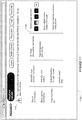
- the identified fault may be provided as an icon for display on the remote computing device, and the icon may have a variable appearance that varies based on the type of fault that has occurred.
- transmitting the identified fault may include providing usage icons for display on the remote computing device, wherein the usage icons indicate an extent to which the patient device was used.
- the disclosure also provides for a system that includes a one or more computing devices configured to perform the methods described herein.
- Fig. 1a shows a system in accordance with the present technology.
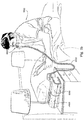
- Fig. 1b shows a system including a patient 1000 wearing a patient interface 3000, in the form of a nasal mask, receives a supply of air at positive pressure from a RPT device 4000. Air from the RPT device is humidified in a humidifier 5000, and passes along an air circuit 4170 to the patient 1000.
- Fig. 1c shows a system including a patient 1000 wearing a patient interface 3000, in the form of a full-face mask, receives a supply of air at positive pressure from a RPT device. Air from the RPT device is humidified in a humidifier 5000, and passes along an air circuit 4170 to the patient 1000.
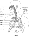
- Fig. 2a shows an overview of a human respiratory system including the nasal and oral cavities, the larynx, vocal folds, oesophagus, trachea, bronchus, lung, alveolar sacs, heart and diaphragm.
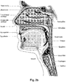
- Fig. 2b shows a view of a human upper airway including the nasal cavity, nasal bone, lateral nasal cartilage, greater alar cartilage, nostril, lip superior, lip inferior, larynx, hard palate, soft palate, oropharynx, tongue, epiglottis, vocal folds, oesophagus and trachea.
- Fig. 2c is a front view of a face with several features of surface anatomy identified including the lip superior, upper vermillion, lower vermillion, lip inferior, mouth width, endocanthion, a nasal ala, nasolabial sulcus and cheilion.
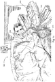
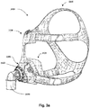
- Fig. 3a shows an example of a patient interface known in the prior art.
- Fig. 4a shows a RPT device in accordance with one form of the present technology.
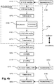
- Fig. 4b shows a schematic diagram of the pneumatic circuit of a RPT device in accordance with one form of the present technology. The directions of upstream and downstream are indicated.
- Fig. 4c shows a schematic diagram of the electrical components of a RPT device in accordance with one aspect of the present technology.
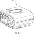
- Fig. 5a shows a humidifier in accordance with one aspect of the present technology.
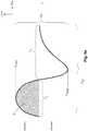
- Fig. 6a shows a model typical breath waveform of a person while sleeping, the horizontal axis is time, and the vertical axis is respiratory flow. While the parameter values may vary, a typical breath may have the following approximate values: tidal volume, Vt, 0.5L, inhalation time, Ti, 1.6s, peak inspiratory flow, Qpeak, 0.4 L/s, exhalation time, Te, 2.4s, peak expiratory flow, Qpeak, -0.5 L/s.
- the total duration of the breath, Ttot is about 4s.
- the person typically breathes at a rate of about 15 breaths per minute (BPM), with Ventilation, Vent, about 7.5 L/s.
- BPM breaths per minute
- a typical duty cycle the ratio of Ti to Ttot is about 40%.
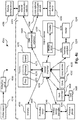
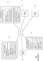
- Fig. 7 shows an example communications system 700 that may be used in monitoring and servicing patient devices.
- Each patient device 720 may comprise an RPT 4000, humidifier 5000, and patient interface 3000.
- Figs. 8-12 show webpages that may be displayed in accordance with aspects of the disclosure.
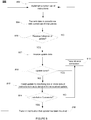
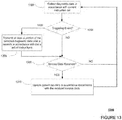
- Fig. 13 shows flow diagram 1300 of operations that may be performed by patient devices disclosed herein in connection with disclosed methods.
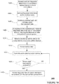
- Fig. 14 shows flow diagram 1400 for operations that may be performed by computing devices, such as servers, disclosed herein.
- the present technology comprises apparatus for treating a respiratory disorder.
- the apparatus may comprise a flow generator or blower for supplying pressurised respiratory gas, such as air, to the patient 1000 via an air delivery tube leading to a patient interface 3000.
- the present technology comprises a method for treating a respiratory disorder comprising the step of applying positive pressure to the entrance of the airways of a patient 1000.
- the present technology comprises a method of treating Obstructive Sleep Apnea in a patient by applying nasal continuous positive airway pressure to the patient.
- a non-invasive patient interface 3000 in accordance with one aspect of the present technology comprises the following functional aspects: a seal-forming structure 3100, a plenum chamber 3200, a positioning and stabilising structure 3300, a vent 3400 and a connection port 3600 for connection to air circuit 4170.
- a functional aspect may be provided by one or more physical components.
- one physical component may provide one or more functional aspects.
- the seal-forming structure 3100 is arranged to surround an entrance to the airways of the patient so as to facilitate the supply of air at positive pressure to the airways.
- a seal-forming structure 3100 provides a sealing-forming surface, and may additionally provide a cushioning function.
- a seal-forming structure 3100 in accordance with the present technology may be constructed from a soft, flexible, resilient material such as silicone.
- the seal-forming structure 3100 comprises a sealing flange and a support flange.
- the sealing flange comprises a relatively thin member with a thickness of less than about 1mm, for example about 0.25mm to about 0.45mm, that extends around the perimeter 3210 of the plenum chamber 3200.
- Support flange may be relatively thicker than the sealing flange.
- the support flange is disposed between the sealing flange and the marginal edge of the plenum chamber 3200, and extends at least part of the way around the perimeter 3210.
- the support flange is or includes a spring-like element and functions to support the sealing flange from buckling in use. In use the sealing flange can readily respond to system pressure in the plenum chamber 3200 acting on its underside to urge it into tight sealing engagement with the face.
- the seal-forming portion of the non-invasive patient interface 3000 comprises a pair of nasal puffs, or nasal pillows, each nasal puff or nasal pillow being constructed and arranged to form a seal with a respective naris of the nose of a patient.
- Nasal pillows in accordance with an aspect of the present technology include: a frusto-cone, at least a portion of which forms a seal on an underside of the patient's nose; a stalk, a flexible region on the underside of the cone and connecting the cone to the stalk.
- the structure to which the nasal pillow of the present technology is connected includes a flexible region adjacent the base of the stalk.
- the flexible regions can act in concert to facilitate a universal joint structure that is accommodating of relative movement-both displacement and angular- of the frusto-cone and the structure to which the nasal pillow is connected.
- the frusto-cone may be axially displaced towards the structure to which the stalk is connected.
- the non-invasive patient interface 3000 comprises a seal-forming portion that forms a seal in use on an upper lip region (that is, the lip superior ) of the patient's face.
- the non-invasive patient interface 3000 comprises a seal-forming portion that forms a seal in use on a chin-region of the patient's face.
- the plenum chamber 3200 has a perimeter 3210 that is shaped to be complementary to the surface contour of the face of an average person in the region where a seal will form in use. In use, a marginal edge of the plenum chamber 3200 is positioned in close proximity to an adjacent surface of the face. Actual contact with the face is provided by the seal-forming structure 3100. Preferably the seal-forming structure 3100 extends in use about the entire perimeter 3210 of the plenum chamber 3200.
- the plenum chamber 3200 may surround and/or be in fluid communication with the nares of the patient where the plenum chamber 3200 is a part of a nasal mask (e.g. shown in Fig 1b ). In another form, the plenum chamber 3200 may surround and/or be in fluid communication with the nares and the mouth of the patient where the plenum chamber 3200 is a part of a full-face mask (e.g., shown in Fig. 1c ). In yet another form, the plenum chamber 3200 may engage and/or be in fluid communication with one or more of the nares of the patient where the plenum chamber 3200 is a part of nasal pillows (e.g., shown in Fig. 29).
- the seal-forming structure 3100 of the patient interface 3000 of the present technology is held in sealing position in use by the positioning and stabilising structure 3300.
- An example RPT device 4000 that may be suitable for implementing aspects of the present technology may include mechanical and pneumatic components 4100, electrical components 4200 and may be programmed to execute one or more of the control methodologies or algorithms described throughout this specification.
- the RPT device may have an external housing 4010, preferably formed in two parts, an upper portion 4012 of the external housing 4010, and a lower portion 4014 of the external housing 4010.
- the external housing 4010 may include one or more panel(s) 4015.
- the RPT device 4000 comprises a chassis 4016 that supports one or more internal components of the RPT device 4000.
- a pneumatic block 4020 is supported by, or formed as part of the chassis 4016.
- the RPT device 4000 may include a handle 4018.
- the pneumatic path of the RPT device 4000 preferably comprises an inlet air filter 4112, an inlet muffler 4122, a controllable pressure device 4140 capable of supplying air at positive pressure (preferably a blower 4142), and an outlet muffler 4124.
- One or more pressure sensors 4272 and flow sensors 4274 are included in the pneumatic path.
- the preferred pneumatic block 4020 comprises a portion of the pneumatic path that is located within the external housing 4010.
- the RPT device 4000 preferably has an electrical power supply 4210, one or more input devices 4220, a central controller 4230, a therapy device controller 4240 and/or any of the controllers previously described, a pressure device 4140, one or more protection circuits 4250, memory 4260, transducers 4270, data communication interface 4280 and one or more output devices 4290. Electrical components 4200 may be mounted on a single Printed Circuit Board Assembly (PCBA) 4202. In an alternative form, the RPT device 4000 may include more than one PCBA 4202.
- PCBA Printed Circuit Board Assembly
- the central controller 4230 of the RPT device 4000 which may include one or more processors, can be programmed to execute one or more algorithm modules, preferably including a pre-processing module, a therapy engine module, a pressure control module, and further preferably a fault condition module. It may further include a vent control module that may be configured with one or more of the vent control methodologies described throughout this specification.
- a RPT device in accordance with one form of the present technology may include an air filter 4110, or a plurality of air filters 4110.
- an inlet air filter 4112 is located at the beginning of the pneumatic path upstream of a blower 4142. See Fig. 4b .
- an outlet air filter 4114 for example an antibacterial filter, is located between an outlet of the pneumatic block 4020 and a patient interface 3000. See Fig. 4b .
- an inlet muffler 4122 is located in the pneumatic path upstream of a blower 4142. See Fig. 4b .
- an outlet muffler 4124 is located in the pneumatic path between the blower 4142 and a patient interface 3000. See Fig. 4b .
- a pressure device 4140 for producing a flow of air at positive pressure is a controllable blower 4142.
- the blower may include a brushless DC motor 4144 with one or more impellers housed in a volute.
- the blower may be preferably capable of delivering a supply of air, for example about 120 litres/minute, at a positive pressure in a range from about 4 cmH 2 O to about 20 cmH 2 O, or in other forms up to about 30 cmH 2 O.
- the pressure device 4140 is under the control of the therapy device controller 4240.
- one or more transducers 4270 are located upstream of the pressure device 4140.
- the one or more transducers 4270 are constructed and arranged to measure properties of the air at that point in the pneumatic path.
- one or more transducers 4270 are located downstream of the pressure device 4140, and upstream of the air circuit 4170.
- the one or more transducers 4270 are constructed and arranged to measure properties of the air at that point in the pneumatic path.
- one or more transducers 4270 are located proximate to the patient interface 3000.
- an anti-spill back valve is located between the humidifier 5000 and the pneumatic block 4020.
- the anti-spill back valve is constructed and arranged to reduce the risk that water will flow upstream from the humidifier 5000, for example to the motor 4144.
- An air circuit 4170 in accordance with an aspect of the present technology is constructed and arranged to allow a flow of air or breathable gasses between the pneumatic block 4020 and the patient interface 3000.
- supplemental oxygen 4180 is delivered to a point in the pneumatic path.
- supplemental oxygen 4180 is delivered upstream of the pneumatic block 4020.
- supplemental oxygen 4180 is delivered to the air circuit 4170.
- supplemental oxygen 4180 is delivered to the patient interface 3000.
- power supply 4210 is internal of the external housing 4010 of the RPT device 4000. In another form of the present technology, power supply 4210 is external of the external housing 4010 of the RPT device 4000.
- power supply 4210 provides electrical power to the RPT device 4000 only. In another form of the present technology, power supply 4210 provides electrical power to both RPT device 4000 and humidifier 5000. The power supply may also optionally provide power to any actuator, controller and/or sensors for a vent arrangement as described throughout this specification
- a RPT device 4000 includes one or more input devices 4220 in the form of buttons, switches or dials to allow a person to interact with the device. These may be implemented for entering settings for operation of the components of the RPT device such as the vent arrangement.
- the buttons, switches or dials may be physical devices, or software devices accessible via a touch screen.
- the buttons, switches or dials may, in one form, be physically connected to the external housing 4010, or may, in another form, be in wireless communication with a receiver that is in electrical connection to the central controller 4230.
- the input device 4220 may be constructed and arranged to allow a person to select a value and/or a menu option.
- the central controller 4230 is a dedicated electronic circuit configured to receive input signal(s) from the input device 4220, and to provide output signal(s) to the output device 4290 and / or the therapy device controller 4240.
- the central controller 4230 is an application-specific integrated circuit. In another form, the central controller 4230 comprises discrete electronic components.
- the central controller 4230 is a processor suitable to control a RPT device 4000 such as an x86 INTEL processor.
- a processor of a central controller 4230 suitable to control a RPT device 4000 in accordance with another form of the present technology includes a processor based on ARM Cortex-M processor from ARM Holdings.
- ARM Cortex-M processor from ARM Holdings.
- an STM32 series microcontroller from ST MICROELECTRONICS may be used.
- Another processor suitable to control a RPT device 4000 in accordance with a further alternative form of the present technology includes a member selected from the family ARM9-based 32-bit RISC CPUs.
- a member selected from the family ARM9-based 32-bit RISC CPUs For example, an STR9 series microcontroller from ST MICROELECTRONICS may be used.
- a 16-bit RISC CPU may be used as the processor for the RPT device 4000.
- the processor is configured to receive input signal(s) from one or more transducers 4270, and one or more input devices 4220.
- the processor is configured to provide output signal(s) to one or more of an output device 4290, a therapy device controller 4240, a data communication interface 4280 and humidifier controller 5250.
- the processor of the central controller 4230 is configured to implement the one or more methodologies described herein such as the one or more algorithms 4300 expressed as computer programs stored in a non-transitory computer readable storage medium, such as memory 4260.
- a non-transitory computer readable storage medium such as memory 4260.
- processor(s) may be integrated with a RPT device 4000.
- the processor(s) may be implemented discretely from the flow generation components of the RPT device 4000, such as for purpose of performing any of the methodologies described herein without directly controlling delivery of a respiratory treatment.
- such a processor may perform any of the methodologies described herein for purposes of determining control settings for a ventilator or other respiratory related events by analysis of stored data such as from any of the sensors described herein.
- such a processor may perform any of the methodologies described herein for purposes controlling operation of any vent arrangement described in this specification.
- RPT device 4000 includes a clock 4232 that is connected to processor.
- therapy device controller 4240 is a pressure control module 4330 that forms part of the algorithms 4300 executed by the processor of the central controller 4230.
- therapy device controller 4240 is a dedicated motor control integrated circuit.
- a MC33035 brushless DC motor controller manufactured by ONSEMI is used.
- a RPT device 4000 in accordance with the present technology comprises one or more protection circuits 4250.
- protection circuit 4250 in accordance with the present technology is an electrical protection circuit.
- protection circuit 4250 in accordance with the present technology is a temperature or pressure safety circuit.
- the RPT device 4000 includes memory 4260, preferably non-volatile memory.
- memory 4260 may include battery powered static RAM.
- memory 4260 may include volatile RAM.
- memory 4260 is located on PCBA 4202.
- Memory 4260 may be in the form of EEPROM, or NAND flash.
- RPT device 4000 includes removable form of memory 4260, for example a memory card made in accordance with the Secure Digital (SD) standard.
- SD Secure Digital
- the memory 4260 acts as a non-transitory computer readable storage medium on which is stored computer program instructions expressing the one or more methodologies described herein, such as the one or more algorithms 4300.
- Transducers may be internal of the device, or external of the RPT device. External transducers may be located for example on or form part of the air delivery circuit, e.g. the patient interface. External transducers may be in the form of non-contact sensors such as a Doppler radar movement sensor that transmit or transfer data to the RPT device.
- a flow transducer 4274 in accordance with the present technology may be based on a differential pressure transducer, for example, an SDP600 Series differential pressure transducer from SENSIRION.
- the differential pressure transducer is in fluid communication with the pneumatic circuit, with one of each of the pressure transducers connected to respective first and second points in a flow restricting element.
- a signal representing total flow Qt from the flow transducer 4274 is received by the processor.
- a pressure transducer 4272 in accordance with the present technology is located in fluid communication with the pneumatic circuit.
- An example of a suitable pressure transducer is a sensor from the HONEYWELL ASDX series.
- An alternative suitable pressure transducer is a sensor from the NPA Series from GENERAL ELECTRIC.
- a signal from the pressure transducer 4272 is received by the central controller processor.
- the signal from the pressure transducer 4272 is filtered prior to being received by the central controller 4230.
- a motor speed signal 4276 is generated.
- a motor speed signal 4276 is preferably provided by therapy device controller 4240.
- Motor speed may, for example, be generated by a speed sensor, such as a Hall effect sensor.
- a data communication interface 4280 is provided, and is connected to central controller processor.
- Data communication interface 4280 is preferably connectable to remote external communication network 4282.
- Data communication interface 4280 is preferably connectable to local external communication network 4284.
- remote external communication network 4282 is connectable to remote external device 4286.
- local external communication network 4284 is connectable to local external device 4288.
- data communication interface 4280 is part of processor of central controller 4230. In another form, data communication interface 4280 is an integrated circuit that is separate from the central controller processor.
- remote external communication network 4282 is the Internet.
- the data communication interface 4280 may use wired communication (e.g. via Ethernet, or optical fibre) or a wireless protocol to connect to the Internet.
- local external communication network 4284 utilises one or more communication standards, such as Bluetooth, or a consumer infrared protocol.
- remote external device 4286 is one or more computers, for example a cluster of networked computers.
- remote external device 4286 may be virtual computers, rather than physical computers. In either case, such remote external device 4286 may be accessible to an appropriately authorised person such as a clinician.
- local external device 4288 is a personal computer, mobile phone, tablet or remote control.
- An output device 4290 in accordance with the present technology may take the form of one or more of a visual, audio and haptic unit.
- a visual display may be a Liquid Crystal Display (LCD) or Light Emitting Diode (LED) display.
- a display driver 4292 receives as an input the characters, symbols, or images intended for display on the display 4294, and converts them to commands that cause the display 4294 to display those characters, symbols, or images.
- a display 4294 is configured to visually display characters, symbols, or images in response to commands received from the display driver 4292.
- the display 4294 may be an eight-segment display, in which case the display driver 4292 converts each character or symbol, such as the figure "0", to eight logical signals indicating whether the eight respective segments are to be activated to display a particular character or symbol.
- Fig. 7 depicts an example system 700 in which aspects of the disclosure may be implemented. This example should not be considered as limiting the scope of the disclosure or usefulness of the features described herein.
- system 700 includes server 710, patient devices 720, storage systems 750, as well as computing devices 760, which in one example may be associated with a clinician or device support service personnel. These devices may each communicate over network 4282.
- System 700 may be scaled to any size network. For example, while only three patient devices 720 are shown, system 700 may include any number of patient devices.
- Each patient device 720 may include one or more devices, including RPT 4000, humidifier 5000, and patient interface 3000. In addition, each patient device 720 may be operated at remote locations and by different patients. While only controller processor 4230 and memory 4260 are shown in patient device 720, each patient device may include any of the components discussed above in connection with RPT 4000, humidifier 5000, and patient interface 3000. In addition, while patient devices 720 are shown as communicating directly over 4282, each patient device may also communicate over network 4282 via an external computing device. For example, patient device 720 may communicate with a personal computer that transmits data over network 4282.
- Servers 710 may contain one or more processors 712, memory 714 and may be incorporated with other components typically present in general purpose computing devices.
- Memory 714 of server 710 may store information accessible by processor 712, including instructions 715 that can be executed by the processor 712.
- Memory 714 may also include data 718 that can be retrieved, manipulated or stored by processor 712.
- the memory can be of any non-transitory type capable of storing information accessible by the processor.
- the instructions 715 may include instructions that are directly or indirectly executed by processor 712.
- the terms "instructions," “application,” “steps” and “programs” can be used interchangeably herein. Functions, methods and routines of the instructions are explained in more detail below.
- Diagnostic data 718 may be retrieved, stored or modified by processor 712 in accordance with the instructions 715.
- the data can be stored in computer registers, in a relational database as a table having many different fields and records, or XML documents.
- Diagnostic data 718 may also be any information sufficient to identify or calculate relevant information, such as numbers, descriptive text, proprietary codes, pointers, references to data stored in other memories such as at other network locations.
- the one or more processors 712 may include conventional processors, such as a CPU, or may be a hardware-based component, such as an ASIC.
- Fig. 7 functionally illustrates the processor, memory, and other elements of server 710, computing device 760 and patient devices 720 as each being within one block
- the various components of each device may be stored within the different physical housings.
- memory 714 may be a hard drive or other storage media located in a housing different from that of servers 710.
- the storage system 750 may be part of, or be housed together with, one or more of the servers 710.
- processor 712 may include a plurality of processors, some or all of which are located in a housing different from that of servers 710. Accordingly, references to a processor, computer, computing device, or memory will be understood to include references to a collection of processors, computers, computing devices, or memories that may or may not operate in parallel.
- some functions are described herein as taking place on a single computing device having a single processor, various aspects of the disclosure may be implemented by a plurality of computing devices communicating information with one another, such as by communicating over network 4282.
- network 4282 and intervening nodes described herein can be interconnected using various protocols and systems, such that the network can be part of the Internet, World Wide Web, specific intranets, wide area networks, local networks, or cell phone networks.
- the network can utilize standard communications protocols, such as Ethernet, Wi-Fi, HTTP and Bluetooth, protocols that are proprietary to one or more companies, and various combinations of the foregoing.
- Servers 710 may include one or more communication servers that are capable of communicating with storage system 750, computing device 760, and patient devices 720 via network 4282. As will be described in greater detail below, servers 710 may receive diagnostic data 728 from the patient devices 720 over network 4282. In response to the received diagnostic data 728, server 710 may also transmit service data 716 to patient devices 720.
- Computing device 760 may be configured similarly to the servers 710, with one or more processors 762, memory 764 and instructions as described above.
- Each computing device may be a personal computing device intended for use by a clinician or a device support service personnel and have all of the components normally used in connection with a personal computing device such as a central processing unit (CPU), memory (e.g., RAM and internal hard drives) storing data and instructions, a display such as a display 766 (e.g., a monitor having a screen, a touch-screen, a projector, a television, or other device that is operable to display information), and user input device 768 (e.g., a mouse, keyboard, touch-screen or microphone).
- CPU central processing unit
- memory e.g., RAM and internal hard drives
- a display such as a display 766 (e.g., a monitor having a screen, a touch-screen, a projector, a television, or other device that is operable to display information)
- system 700 may implement security measures so as to prevent unauthorized access to transmitted data.
- the connection between devices of system 700 may take the form of a VPN connection.
- data transmission may be based on secure socket layer (SSL) protocols.
- SSL secure socket layer
- Transmitted data over network 4282 may also be encrypted using a private key infrastructure. While aspects of the system below provide for data to be presented over one or more webpages, these webpages may be presented in connection with a protected network, so that the webpages may only be accessible to authorized computing devices and users.
- each patient devices 720 shown in Fig. 7 may include one or more devices, including RPT 4000, humidifier 5000, and patient interface 3000.
- patient devices 720 may implement instruction sets 726, which may include software or firmware.
- RPT 4000 may include multiple controllers, such as humidity controller 5290 and therapy device controller 4240, as well as other hardware components.
- a fault may occur in connection with one or more components. As set forth in the systems and methods described herein, these faults may be identified, and often serviced, remotely.
- the disclosed system allows service personnel to receive real-time notifications and diagnostic data relating to patient devices 720, so that potential problems may be identified even before a patient reports a problem with his or her patient device 720. If a problem is reported by a patient, the disclosed system provides the service personnel with visible indications of the fault, such as through the display of error icons and warning messages on a webpage or on a patient device dashboard, and provides a related report of detailed data relating to operation patient device. In this way, the service personnel may quickly determine whether the patient's reported problem is device related or not.
- Each patient device 720 may generate and store diagnostic data 728. Diagnostic data 728 may include any data related to the operation of patient device 720, including data relating to faults that have occurred or are likely to occur.
- instruction sets 726 may include instructions to perform comprehensive checks of patient device 720 in order to determine whether the various components of patient device 720 are operating correctly. For example, a comprehensive check may entail checking the power supply, the air pressure being provided over patient interface 3000, as well as the temperature of one or more components of patient device 720.
- faults may be categorized based on the components and operations that are effected, such as categorizing a fault as relating to humidification, the heated tube, the power supply, the blower, or the like.
- a particular fault may be categorized based on whether it requires a patient to stop using the device.
- patient device 720 may determine whether the detected fault is of a category that would require the patient to stop using the device, and, if so, terminating treatment to the patient.
- Patient device 720 may also display an error message to the patient. The error message may describe the fault that has occurred or is likely to occur.
- Diagnostic data 728 is not limited to the identification of specific faults in the patient device but may also relate to the general operation and use of the device.
- patient device 720 may generate a log of a patient's usage of patient device 720, including identifying the time periods of use, the air pressure provided during use, air leaks that occurred during use, as well as therapeutic settings that have been used during treatment. These therapeutic settings may include various climate controls that can be set for automatic or manual adjustment. For example, a user may set the humidity, temperature, and expiratory pressure levels of the patient device 720. The patient may also set patient device 720 to a "smart start" and "smart stop” setting, in which patient device 720 will automatically begin treatment upon the patient putting on patient interface 3000 and will automatically stop treatment upon the patient taking off patient interface 3000.
- Diagnostic data may also relate to a patient's condition during treatment.
- diagnostic data 728 may include data that can be used to calculate a patient's apnea index, hypopnea index, and apnea-hyponea index, fault data, patient usage, leak data, therapy and comfort settings and order device activity and fault logs.
- Ambient conditions for patient device 720 may also be collected and stored as diagnostic data.
- sensors in the patient device may be used to collect data related to the temperature and humidity of the patient device's surroundings. Such additional data can be collected to assist in diagnosing the reported problem in a more holistic way, as it presents a more complete picture of the environment within which the monitored device operates.
- diagnostic data 728 may be collected and presented as a log of events or operations that have been performed by patient device 720.
- the log may identify instances when a fault has occurred, including identifying the particular component or components for which a fault has occurred or is likely to occur. Details on how operational parameters can be used as an indication of a likely fault in various components of a pressure treatment device are described in the published PCT application WO 2000027457 .
- the log may comprise a list of events and operations, as well as the date and time that each event occurred.
- patient device 720 may transmit collected diagnostic data 728 to one or more external devices, such as servers 710 and computing device 760.
- the transmission of diagnostic data 728 may occur at a regular interval, such as once a day or once a week, or may be based on the occurrence of a predetermined triggering event.
- One such triggering event may be the occurrence of a fault, so that diagnostic data 728 is transmitted as soon as a fault is detected.
- patient device may also transmit other diagnostic data 728, including therapeutic treatment information and device settings.
- the triggering event may also be based on a predetermined time period after which the patient has stopped using patient device 720.
- instruction set 726 may indicate that diagnostic data 728 should be transmitted one hour after a patient has stopped using patient device 720. In this example, if the patient stops using patient device 720, but then resumes using it within one hour, diagnostic data 728 will not be sent. Instead, patient device 720 will wait until the patient's use of patient device 720 has stopped for the designated time period of one hour before sending diagnostic data 728. By waiting a predetermined time period before sending diagnostic data 728, instruction set 726 may prevent unnecessary transmissions of usage data that are due to brief interruptions to treatment, such as when the patient adjusts or briefly removes patient interface 3000.
- the predetermined time period used to trigger the transmission of diagnostic data 728 may be configurable for the particular instruction set 726 being implemented by a specific patient device.
- instruction set 726 may designate a triggering event based on the amount of time that a patient has received treatment with patient device 720. This time period may also be configurable within the instruction set 726 so as to balance between limiting the amount of data that is transferred over network 4282 and achieving timeliness of diagnostic data. Instruction set 726 may also cause patient device 720 to transmit diagnostic data 728 in the event that no treatment has occurred over a predetermined time period. For example, patient device 720 may transmit diagnostic data 728 to server 710 indicating that patient device 720 has not been used in a predetermined number of hours, such as twenty-four hours.
- server 710 may store the received data as diagnostic data 718.
- the stored diagnostic data at server 710 may be accessed by computing device 760, so that a user of computing device 760, such as service personnel, may monitor the condition of each patient device.
- diagnostic data 718 may be stored at server 710 in a manner that associates the diagnostic data 718 with a particular patient device 720 and a particular patient. In this way, service personnel may easily detect any issues with a particular patient device 720.
- Diagnostic/fault data 728 stored at patient devices 720 may also be provided on demand to allow for immediate review. For example, immediate review of diagnostic data 728 may be needed if the user of patient device 720 calls service personnel due to a problem with the operation of patient device 720. In this instance, the service personnel may use computing device 760 to request for immediate transmittal of particular diagnostic data from patient device 720, such as all diagnostic data 728 that was collected over a particular time period, including any diagnostic data 728 relating to faults that have been detected or reported by the user.
- servers 710 may include different types of servers, including communication servers and web servers.
- computing device 760 may make a request for diagnostic data 728 to a web server, which in turn transmits the request to a communication server.
- the communication server may then request and receive diagnostic data 728 from patient device 720.
- patient device 720 may transmit diagnostic data 728 as a log of operations and faults.
- the received log may then be transmitted from the web server to the communication server, where it can be accessed by computing device 760.
- users of computing device 760 may access diagnostic data 718 that has been stored on server 710.
- the accessed diagnostic data 718 may be presented to computing device 760 via a website or some other network interface.
- a user of computing device 760 may search for particular diagnostic data 718, based on patient information.
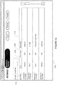
- Fig. 8 shows a screenshot 800 of webpage that may be displayed in connection with a search of diagnostic data based on a patient's name.
- Screenshot 800 includes a search field 802, which may be used to input a search query for one or more patients.
- the search field may be set to search particular attributes of patients, including the patient's name, date of birth, identification number, and the like.
- a search has been performed for patients having the name "Doe.”
- Doe the proposed system clinicians can now see not only a list of their patients, but can also see, at a glance, whether any of their patients has a device with a fault such as a hardware fault.
- the system can also filter the patients to only show those patients that have devices with a fault or without a fault, depending on what is required by the threating clinician. In this way, the clinician could pro-actively manage their patients that have devices with problems rather than waiting for a phone call.
- the results of the search are shown under column headings 804-812.
- the name of each patient that satisfies the search query appears under column heading 806.
- any device that the patient is using may be identified within the same row of the identified patient under column heading 812.
- the identification of the patient devices in screenshot 800 provides model numbers for each device used by the patient, however column heading 812 may include additional information about the device, including identification of the device's manufacturer and the device's serial number.
- an icon 814 may be displayed for any patient device that has experienced a fault or is likely to develop one. For example, icon 814 is displayed next to the name "John Doe," indicating that John Doe's model S10 Newport device has experienced a fault.
- Icon 814 may take any number of forms and may change based on the type of fault that has occurred. For example, icon 814 may have a variable appearance depending what component of the patient device has experienced a fault, whether the fault has caused the patient device to stop operating, and whether the patient has reported the fault. In this way, service personnel may quickly identify the nature of the problem and determine what additional actions should be considered. The service personnel may also use the appearance of icon 814, as well as any reports provided along with icon 814, to determine if an issue that has been reported by a patient is device related or not. For example, non-device related issues may include problems that arise from environmental issues or patient related issues.
- the webpage shown in screenshot 800 may also display other diagnostic data associated with each patient's device.
- icons under column heading 804 provide an indication of whether a patient's device is currently connected to the network.
- icon 816 indicates that John Doe's device is currently connected to the network
- icon 818 indicates that Robert Doe's device is not currently connected to the network.
- the dates listed under column heading 810 indicate the date on which the patient last used the patient device.
- the user of computing device 760 may customize the webpage display shown in Fig. 8 , so as to display additional information for each patient device.
- the webpage may provide additional diagnostic data for particular patient devices via a popup window.
- pop-up window 902 appears when the user moves cursor 904 over icon 814.
- a pop-up window may identify the specific patient device for which the fault has been detected, as well as additional information regarding the patient.
- pop-window 902 identifies the patient, John Doe, by patient ID, 987-654-321, and identifies the patient device by a serial number, 123456789.
- Pop-window 902 may also display information regarding the fault that has been detected for a patient device.
- warning icon 906 indicates that a fault has occurred in connection with the blower of device 123456789
- check icon 908 indicates that no fault has been detected in connection with the device's power supply.
- the user may select warning icon 906 in order to receive additional details regarding the detected fault, including the specific data indicating the fault, the date and time the fault was first detected, the current setting of the patient device, etc.
- faults could be associated with any component, sub-system of functional area and the discussed examples such as a blower (flow generator) and power supply units are only examples to illustrate the system capability.
- Fig. 10 shows another manner in which diagnostic data may be displayed to a user.
- the webpage may display diagnostic data in connection with a list of devices, rather than a list of patients.
- the patient device information may be presented without any specific identification of the patient, so as to maintain patient privacy with respect to service personnel.
- diagnostic data for patient devices may be accessed based on a device identifier, such as a serial number.
- a device identifier such as a serial number.
- specific patient devices may be listed by their serial numbers, with any fault indications being provided under column 1004. Additional diagnostic data may be shown in other columns.
- the graphics shown under column heading 1006 indicate usage of each patient device over the last ten days.
- each usage icon 1010-1018 indicates the extent to which patient device 987654321 was used over the course of a particular day.
- a blank usage icon 1010 indicates that patient device 987654321 was not used on May 1 st .
- usage icon 1012 indicates that the patient used the patient device for at least some predetermined amount of time, such as 6 hours, on May 6 th .
- the partially shaded usage icon 1014 indicates that the patient device was used on May 2 nd , however the device was not used for the predetermined amount of time.
- Usage icons 1010-1018 may also indicate the manner in which the patient device was used. For example, the "L" shown in usage icon 1016 may indicate that air leak was detected during the patient's treatment on May 4 th .
- the "M" shown in icon 1018 may designate that the device is currently being monitored or that diagnostic data has not yet been received for that day.
- a user may obtain additional information in connection with the fault indicated by icon 1020 by moving a cursor over or selecting icon 1020.
- the user may select one of the usage icons 1010-1018 in order to receive a log of diagnostic data for patient device 987654321 in connection with a particular day, as well as diagnostic data relating to the settings of one or more patient device components at the time the fault occurred.
- the diagnostic data may identify whether automatic climate control settings were activated at the time of the fault or humidity level setting of the patient device at the time of the fault.
- the log may include all operations and faults that occurred over a designated time period.
- a patient's home care provider or the associated service personnel may use system 700 of Fig. 7 to troubleshoot a particular patient device 720. If a patient experiences a problem with the patient device 7720, the HCP may use computing device 760 to access diagnostic data 718 stored on server 710 for a particular patient device 720. Upon entering identifying information, such as a serial number, for patient device 720, server 710 may provide computing device 760 with a troubleshooting webpage, such as the webpage shown in screenshot 1100 of Fig. 11 . This webpage may clearly display a message indicating whether a fault has been detected for the selected device. For example, the webpage of screenshot 1100 displays fault message 1102, which indicates that a fault has occurred.
- identifying information such as a serial number
- This message may indicate the nature of the fault, as well as provide instructions as to how the fault may be addressed.
- server 710 may determine if the detected fault may be addressed remotely. If so, the fault message may provide a phone number or webpage link to be used in seeking assistance with the fault. Alternatively, if it is determined that the fault cannot be addressed remotely, the message may indicate that the patient should bring the patient device into a service center for the fault to be address. If the diagnostic data 718 stored at server 710 does not indicate that a fault has occurred, a message may be provided on the webpage stating that no fault has been detected.
- Determining whether a fault may be addressed remotely may be based, at least in part, on whether diagnostic data 718 indicates that the fault for patient device 720 is based on a particular form of hardware failure, as some faults that are based on hardware failure will need to be addressed at a service center. In these instances, troubleshooting may end immediately, and the patient may be instructed to take the patient device in for servicing.
- some hardware problems may also be addressed remotely by providing instructions to the HCP or patient over the troubleshooting webpage.
- the fault may be addressed remotely by server 710.
- server 710 may perform troubleshooting by transmitting an update of instruction set 726 to patient device 720 over network 4282.
- the troubleshooting webpage shown in Fig. 11 may display various information about patient device 720, including the device's model number and serial number.
- the troubleshooting webpage may also display the device's current settings, such as expiratory pressure relief, smart start/stop, climate control options, humidification settings, heated tube temperature settings, and the like.
- the troubleshooting webpage may also display environmental diagnostic data, such as the temperature and humidity of the patient's room at or near the time the fault occurred.
- the troubleshooting webpage may display usage data, such as the five days of usage icons 1104 displayed in screenshot 1100.
- this usage data may indicate the amount of time the patient has used the patient device, the extent to which air leaks have been detected, as well as data relating to the patient's apnea-hypopnea index.
- the ambient conditions for the patient device may also be displayed on the troubleshooting webpage.
- Identification of various components being used by the patient such as the type of humidifier 5000 and the type of patient interface 3000, may also be identified on the troubleshooting webpage. This information may be used by an HCP to determine the manner in which the fault is to be addressed. For example, a fault associated with an air leak may be addressed in different ways, depending on the type of mask that is being used by the patient. As shown in Fig.
- information may be provided on the troubleshooting webpage regarding the type of mask being used, along with recent leak information for patient device 720.
- the mask information may be used as indicators relating to unexpected stoppage in therapy or poor mask fit and may include identification of the design, size, and brand of the mask being used with patient device 720.
- an HCP may identify what has caused the fault and adjust the settings of patient device 720 in order to address the problem.
- an HCP may adjust the patient's therapy and the settings of patient device 720 by inputting the adjustments directly into the troubleshooting webpage.
- an HCP may use the troubleshooting webpage in Fig. 11 to adjust the humidity level of device 123456789 from level 5 to level 3.
- the altering the humidity level in the troubleshooting webpage may be received by server 710 shown in Fig. 7 .
- server 710 may transmit a humidity alteration command to patient device 720.
- Patient device 720 may then alter its humidity level in response to the received command.
- server 710 may transmit diagnostic data 718 to computing device 760 in the form of a diagnostic log of operations and faults.
- the user of computing device 760 may request a diagnostic log from server 710 for one or more patient devices 720. This request may specify the type of diagnostic data that is to be included in the log.
- user through computing device 760, may request a diagnostic log for all faults that have occurred for a particular patient device.
- the user may request a log of all diagnostic data related to a particular component or set of components, such as humidifier 5000.
- the user of computing device may be provided with a specific set of information that can be used in addressing problems that have occurred in connection with patient device 720.
- Screenshot 1200 of Fig. 12 shows an example diagnostic log that may be displayed on a computing device.
- the computing device has requested a log of all activities and faults that have occurred over the last 24 hours on the patient device having serial number 123456789.
- the dates and time identified under column heading 1204 indicate the date and time of each fault that has occurred, while the information under column heading 1206 designates whether the entry relates to an activity or a fault.
- an error code may be identified for each fault. This allows service personnel to identify the specific type of fault that has occurred.
- each log entry may include a description, as provided under column heading 1210. The description of the log entry may identify the activity that has occurred, such as the user putting on or taking off the device's mask, or may provide information about a fault that has occurred.
- the diagnostic log presented to a user may be expanded or filtered based on user input.
- the diagnostic log shown in Fig. 12 may be expanded to include activities and faults that have occurred for device 123456789 over a long period of time, such as the last 30 days.
- the diagnostic log may also be filtered so that it only shows a particular type of activity or so that it only shows faults that have occurred on the patient device. In this way, a user may easily access the information needed in servicing a patient device.
- server 710 of Fig. 7 may transmit a fault indication to computing device 760 as soon as a fault has been detected in one of the patient devices 720. Accordingly, instead of waiting for a request for diagnostic data, server 710 may push a notification to computing device 760 as soon as the diagnostic data for patient device 720 indicates that a fault has occurred. This notification may occur as an SMS message, e-mail, or some other form of push notifications. In this way, HCPs or service personnel may be immediately notified of problems with patient devices 720. In one example, a push notification will only be provided for certain types of faults, such has faults that may negatively affect a patient's treatment. Accordingly, upon receiving an indication of a fault from patient device 720, server 710 may determine whether the identified fault is one for which a push notification is to be transmitted to computing device 760.
- Fig. 13 is a flow diagram 1300 that may be performed by a patient device of the disclosed system described above.
- the patient device collects diagnostic data in accordance with an instruction set.
- diagnostic data may include operations and faults that occur in connection with the patient device, as well as identification of settings for the patient device.
- patient device determine whether a triggering event has occurred (Block 1304). Once a triggering event has been identified, the patient device may transmit at least a portion of the diagnostic data over a network, such as transmitting the diagnostic data to a server (Block 1306).
- a triggering event may be based on actions performed by the patient or operations performed by the patient device.
- a triggering event may be based on a determination that the patient has stopped using the patient device for a predetermined period of time.
- a triggering event may also include receiving a request for diagnostic data from an external device, such as a server.
- the request or trigger event may require the patient device to transmit a particular portion of the collected diagnostic data.
- the patient device may transmit all diagnostic data that has been collected since the last transmission.
- the patient device may also determine whether service data has been received (Block 1308).
- Service data may include information provided by a remote service in attempt to address an identified fault.
- service data may include an update to the patient device's software or firmware or an update to one or more of the patient device's settings. If service data has not been received, the patient device may continue to collect diagnostic data and determine whether a triggering event has occurred in accordance with Blocks 1302 and 1304. However, if service data has been received, the patient device may update itself in accordance with the received service data (Block 1310). The update may include adding new instruction sets, altering current instruction sets, or altering the settings of the patient device. The patient device may then continue to collect diagnostic data (Block 1302) and transmit diagnostic data (Block 1306) in accordance with the current instruction set, which may include updates instructions.
- Fig. 14 shows flow diagram 1400 that may be performed by computing devices of the disclosed system, including server 710 of system 700.
- a server may receive a query for diagnostic data associated with one or more patient devices.
- server 710 may receive a query from computing device 760 seeking data in connection with a particular patient device or set of patient devices.
- This query may seek identification of all patient devices that meet one or more criteria provided by a user of computing device 760.
- the criteria may be based on any number of aspects or features of the patient device, including devices that have experienced faults over some defined time period. In this way, the user of computing device 760 may be made aware of faults shortly after they occur, possibly even before the patient has noted the problem or has notified the user of the problem.
- the server may access diagnostic data in response to the received query (Block 1404), and may determine whether a fault has occurred in connection with the one or more patient devices (Block 1406).
- the server may respond to the query by transmitting diagnostic data for one or more patient devices, including identification of any faults that have occurred for the one or more patient devices (Block 1408).
- the transmission of diagnostic data may occur over one or more webpages, such as the webpages shown in Figs. 8-12 .
- the webpage may identify specific faults that have occurred for one or more patient devices, as well as potential actions that should be taken in connection with each identified fault.
- the server may then receive a request for service data to be transmitted to one or more patient devices (Block 1410).
- the transmitted service data may take the form of a command to adjust to one or more device settings or updates to the patient device instruction set. For example, in addressing an identified fault of condensation in the conduit of a patient device, the user of computing device 760 may select specific setting changes to be transmitted as service data to the patient device, so as to adjust the level of humidification being provided by the humidifier of the patient device.
- the server may access or otherwise generate service data (Block 1412) and transmit the service data to the patient devices identified in the received request (Block 1414). The server may also determine if the transmission of the service was successful (Block 1416).
- the server may receive from each patient device either an error notification or a message that the service data was successfully implemented. If an error occurred in the transmission of the service data, the server may transmit the service data again for each patient device for which the error occurred (Block 1414). However, if the transmission is successful, the server may revise the stored diagnostic data to indicate that the one or more patient devices have implemented the transmitted service data (Block 1418).
- Figs. 13 and 14 may each be performed by a single device, the operations may alternatively be performed by more than one device.
- a patient device may communicate with a personal computer over a wireless network, so that the personal computer may perform one or more of the operations described above.
- the server referenced in connection with Figs. 14 and 9 may also include a plurality of servers, with each server performing one or more of the operations described above.
- Various operations may be added or removed from flow diagrams 1300 and 1400.
- a system in accordance with the current disclosure may perform the methods associated with flow diagram 1400 without performing the procedures described in Block 1412 to Block 1418.
- various operations need not be performed in the same order as set forth in flow diagrams 1300 and 1400.
- Air will be taken to include breathable gases, for example air with supplemental oxygen.
- CPAP treatment will be taken to mean the application of a supply of air or breathable gas to the entrance to the airways at a pressure that is continuously positive with respect to atmosphere, and preferably approximately constant through a respiratory cycle of a patient.
- the pressure at the entrance to the airways will vary by a few centimeters of water within a single respiratory cycle, for example being higher during inhalation and lower during exhalation.
- the pressure at the entrance to the airways will be slightly higher during exhalation, and slightly lower during inhalation.
- the pressure will vary between different respiratory cycles of the patient, for example being increased in response to detection of indications of partial upper airway obstruction, and decreased in the absence of indications of partial upper airway obstruction.
- Silicone or Silicone Elastomer A synthetic rubber.
- a reference to silicone is a reference to liquid silicone rubber (LSR) or a compression moulded silicone rubber (CMSR).
- LSR liquid silicone rubber
- CMSR compression moulded silicone rubber
- SILASTIC included in the range of products sold under this trademark
- Another manufacturer of LSR is Wacker.
- a preferred form of LSR has a Shore A (or Type A) indentation hardness in the range of about 35 to about 45 as measured using ASTM D2240.
- Polycarbonate a typically transparent thermoplastic polymer of Bisphenol-A Carbonate.
- Anti-asphyxia valve The component or sub-assembly of a mask system that, by opening to atmosphere in a failsafe manner, reduces the risk of excessive CO 2 rebreathing by a patient.
- Elbow A conduit that directs an axis of flow of air to change direction through an angle.
- the angle may be approximately 90 degrees. In another form, the angle may be less than 90 degrees.
- the conduit may have an approximately circular cross-section. In another form the conduit may have an oval or rectangular cross-section.
- Frame will be taken to mean a mask structure that bears the load of tension between two or more points of connection with a headgear.
- a mask frame may be a non-airtight load bearing structure in the mask. However, some forms of mask frame may also be air-tight.
- Headgear will be taken to mean a form of positioning and stabilizing structure designed for use on a head.
- the headgear comprises a collection of one or more struts, ties and stiffeners configured to locate and retain a patient interface in position on a patient's face for delivery of respiratory therapy.
- Some ties are formed of a soft, flexible, elastic material such as a laminated composite of foam and fabric.
- Membrane will be taken to mean a typically thin element that has, preferably, substantially no resistance to bending, but has resistance to being stretched.
- Plenum chamber a patient interface plenum chamber will be taken to mean a portion of a patient interface having walls enclosing a volume of space, such as for a full-face mask (e.g., nose and mouth mask), a nasal mask or a nasal pillow, the volume having air therein pressurised above atmospheric pressure in use by the patient.
- a shell may form part of the walls of a patient interface plenum chamber. In one form, a region of the patient's face abuts one of the walls of the plenum chamber, such as via a cushion or seal.
- the noun form (“a seal") will be taken to mean a structure or barrier that intentionally resists the flow of air through the interface of two surfaces.
- the verb form (“to seal”) will be taken to mean to resist a flow of air.
- a shell will preferably be taken to mean a curved structure having bending, tensile and compressive stiffness, for example, a portion of a mask that forms a curved structural wall of the mask. Preferably, compared to its overall dimensions it is relatively thin. In some forms, a shell may be faceted. Preferably such walls are airtight, although in some forms they may not be airtight.
- a stiffener will be taken to mean a structural component designed to increase the bending resistance of another component in at least one direction.
- a strut will be taken to be a structural component designed to increase the compression resistance of another component in at least one direction.
- Swivel (noun) A subassembly of components configured to rotate about a common axis, preferably independently, preferably under low torque.
- the swivel may be constructed to rotate through an angle of at least 360 degrees.
- the swivel may be constructed to rotate through an angle less than 360 degrees.
- the sub-assembly of components preferably comprises a matched pair of cylindrical conduits. Preferably there is little or no leak flow of air from the swivel in use.
- Tie A tie will be taken to be a structural component designed to resist tension.
- Vent (noun) the structure that allows a deliberate controlled rate leak of air from an interior of the mask, or conduit to ambient air, to allow washout of exhaled carbon dioxide (CO 2 ) and supply of oxygen (O 2 ).
- any and all components herein described are understood to be capable of being manufactured and, as such, may be manufactured together or separately.
- LIST OF REFENCE NUMBERS system 700 server 710 processor 712 memory 714 instruction 715 service data 716 diagnostic data 718 patient device 720 instruction set 726 diagnostic data 728 storage system 750 computing device 760 processor 762 memory 764 display 766 user input device 768 screenshot 800 search field 802 column heading 804-812 icons 814-818 screenshot 900 window 902 cursor 904 warning icon 906 check icon 908 patient 1000 screenshot 1000 column 1002 column 1004 column heading 1006 blank usage icon 1010 icons 1012-1020 screenshot 1100 fault message 1102 usage icon 1104 screenshot 1200 column headings 1204-1210 patient interface 3000 seal-forming structure 3100 plenum chamber 3200 perimeter 3210 vent 3400 connection port 3600 RPT device 4000 external housing 4010 upper portion of external housing 4012 lower portion of external housing 4014 panel 4015 chassis 4016 handle 4018 pneumatic block 4020 pneumatic component 4100 air filter
Claims (12)
- System (700) zur diagnostischen Überwachung von Patienten-Atemtherapievorrichtungen (720,730,740), die eine oder mehrere Rechenvorrichtungen (710) aufweisen, wobei die eine oder die mehreren Rechenvorrichtungen (710) konfiguriert sind zum:Empfangen (1404) von Diagnosedaten von mehreren Patienten-Atemtherapievorrichtungen, wobei die Diagnosedaten ein Vorhandensein eines Fehlers in mindestens einer der mehreren Patienten-Atemtherapievorrichtungen identifizieren;Speichern der Diagnosedaten;Identifizieren (1406) des Vorhandenseins des Fehlers in einer ersten Patienten-Atemtherapievorrichtung anhand eines ersten Teils der Diagnosedaten;Senden (1408) des ersten Teils der Diagnosedaten und/oder des identifizierten Fehlers an eine entfernte Vorrichtung (760) als Reaktion auf eine Anfrage von der entfernten Vorrichtung; undSenden (1414) von Servicedaten, die anhand des ersten Teils der Diagnosedaten oder eines identifizierten Fehlers identifiziert wurden, an die erste Patienten-Atemtherapievorrichtung, wobei das System ferner die mehreren Patienten-Atemtherapievorrichtungen (720, 730, 740) aufweist und jede Patienten-Atemtherapievorrichtung konfiguriert ist zum:Sammeln (1302) von Diagnosedaten mit Bezug zum Betrieb der Patienten-Atemtherapievorrichtung, wobei die Diagnosedaten ein Vorhandensein eines Fehlers in Verbindung mit der Patienten-Atemtherapievorrichtung identifizieren;Feststellen (1304), dass ein auslösendes Ereignis aufgetreten ist, für das Diagnosedaten über ein Netzwerk gesendet werden sollen, wobei das auslösende Ereignis auf einer Feststellung basiert, dass ein Patient die Verwendung einer Patienten-Atemtherapievorrichtung für einen vorbestimmten Zeitraum eingestellt hat;Senden (1306) der Diagnosedaten über das Netzwerk an die eine oder mehreren Rechenvorrichtungen, wobei mindestens ein erster Teil der Diagnosedaten so konfiguriert ist, dass das Vorhandensein des Fehlers von einer Rechenvorrichtung identifizierbar ist;Empfangen (1308) von Servicedaten, die sich auf einen von der einen oder mehreren Rechenvorrichtungen identifizierten Fehler richten; undDurchführen (1310) von einer oder mehreren Operationen entsprechend den empfangenen Servicedaten.
- System nach Anspruch 1, wobei das System auch konfiguriert ist zum Empfangen der Identifikation der an die erste Patienten-Atemtherapievorrichtung zu sendenden Servicedaten, wobei mindestens ein Teil der Servicedaten sich auf einen identifizierten Fehler richten.
- System nach einem der vorstehenden Ansprüche, wobei die Diagnosedaten mindestens eines der folgenden umfassen: den Apnoe-Index, den Hypopnoe-Index, den Apnoe-Hypopnoe-Index eines Patienten, Fehlerdaten, Patientennutzung, Leckdaten, Luftfeuchtedaten, Therapie- und Komforteinstellungen sowie Bestellgeräteaktivitäts- und -ehlerprotokolle.
- System nach einem der vorstehenden Ansprüche, wobei die eine oder die mehreren Rechenvorrichtungen ferner konfiguriert sind zum:Empfangen eines Hinweises von der ersten Patienten-Atemtherapievorrichtung, dass die Servicedaten erfolgreich gesendet wurden; undAktualisieren der Diagnosedaten zum Anzeigen der Umsetzung der Servicedaten durch die erste Patienten-Atemtherapievorrichtung.
- System nach einem der vorstehenden Ansprüche, wobei die Diagnosedaten mindestens eines der folgenden umfassen: den Apnoe-, den Hypopnoe-, oder den Apnoe-Hypopnoe-Index des Patienten, Therapieeinstellungen, Komforteinstellungen, Fehlerdaten, Patientennutzung, Leckdaten, Luftfeuchtedaten, Therapie- und Komforteinstellungen sowie Bestellgeräteaktivitäts- und -fehlerprotokolle der Patienten-Atemtherapievorrichtung.
- System nach einem der vorstehenden Ansprüche, wobei das Senden des ersten Teils der Diagnosedaten eine Push-Benachrichtigung an eine entfernte Rechenvorrichtung umfasst und wobei die Push-Benachrichtigung auf einer Feststellung basierend gesendet wird, dass ein identifizierter Fehler von einem Typ ist, für den eine Push-Benachrichtigung bereitgestellt werden soll.
- System nach einem der vorstehenden Ansprüche, wobei die Servicedaten einen Befehl zum Anpassen einer oder mehrerer Einstellungen der ersten Patienten-Atemtherapievorrichtung umfassen.
- System nach einem der vorstehenden Ansprüche, wobei die Diagnosedaten eine oder mehrere Einstellungen der ersten Patienten-Atemtherapievorrichtung zum Zeitpunkt des Auftretens des Fehlers identifizieren.
- System nach einem der vorstehenden Ansprüche, wobei das Senden des identifizierten Fehlers ferner das Bereitstellen von Nutzungssymbolen zur Anzeige auf der entfernten Rechenvorrichtung umfasst, wobei die Nutzungssymbole einen Umfang anzeigen, in dem die erste Patienten-Atemtherapievorrichtung genutzt wurde.
- System nach einem der vorstehenden Ansprüche, wobei das auslösende Ereignis zusätzlich darauf basiert, dass eine oder mehrere Bedingungen erfüllt sind, bevor die Diagnosedaten gesendet werden.
- System nach einem der Ansprüche 1-10, wobei das auslösende Ereignis zusätzlich auf einem Plan basiert, gemäß dem Diagnosedaten gesendet werden sollen.
- System nach einem der vorstehenden Ansprüche, wobei die Diagnosedaten Leckangaben und die Identikation eines Maskentyps, der mit der Patienten-Atemtherapievorrichtung verwendet wird, umfassen.
Priority Applications (1)
| Application Number | Priority Date | Filing Date | Title |
|---|---|---|---|
| EP20217809.1A EP3863021A1 (de) | 2014-05-27 | 2015-05-27 | Ferndiagnose von atemtherapievorrichtungen |
Applications Claiming Priority (2)
| Application Number | Priority Date | Filing Date | Title |
|---|---|---|---|
| AU2014901997A AU2014901997A0 (en) | 2014-05-27 | Managing remotely respiratory therapy devices | |
| PCT/AU2015/050282 WO2015179917A1 (en) | 2014-05-27 | 2015-05-27 | Remote diagnostics of respiratory therapy devices |
Related Child Applications (1)
| Application Number | Title | Priority Date | Filing Date |
|---|---|---|---|
| EP20217809.1A Division EP3863021A1 (de) | 2014-05-27 | 2015-05-27 | Ferndiagnose von atemtherapievorrichtungen |
Publications (3)
| Publication Number | Publication Date |
|---|---|
| EP3148418A1 EP3148418A1 (de) | 2017-04-05 |
| EP3148418A4 EP3148418A4 (de) | 2018-01-31 |
| EP3148418B1 true EP3148418B1 (de) | 2021-01-06 |
Family
ID=54697731
Family Applications (2)
| Application Number | Title | Priority Date | Filing Date |
|---|---|---|---|
| EP20217809.1A Pending EP3863021A1 (de) | 2014-05-27 | 2015-05-27 | Ferndiagnose von atemtherapievorrichtungen |
| EP15800058.8A Active EP3148418B1 (de) | 2014-05-27 | 2015-05-27 | Ferndiagnose von atemtherapievorrichtungen |
Family Applications Before (1)
| Application Number | Title | Priority Date | Filing Date |
|---|---|---|---|
| EP20217809.1A Pending EP3863021A1 (de) | 2014-05-27 | 2015-05-27 | Ferndiagnose von atemtherapievorrichtungen |
Country Status (4)
| Country | Link |
|---|---|
| US (3) | US10569036B2 (de) |
| EP (2) | EP3863021A1 (de) |
| JP (4) | JP6697401B2 (de) |
| WO (1) | WO2015179917A1 (de) |
Families Citing this family (38)
| Publication number | Priority date | Publication date | Assignee | Title |
|---|---|---|---|---|
| US8019567B2 (en) | 2007-09-17 | 2011-09-13 | Ecofactor, Inc. | System and method for evaluating changes in the efficiency of an HVAC system |
| CN106983940B (zh) | 2011-07-13 | 2021-01-26 | 费雪派克医疗保健有限公司 | 叶轮和马达组件 |
| GB2539122B (en) | 2012-03-15 | 2017-03-15 | Fisher & Paykel Healthcare Ltd | Respiratory gas humidification system |
| GB2575894A (en) | 2012-04-27 | 2020-01-29 | Fisher & Paykel Healthcare Ltd | Usability features for respiratory humidification system |
| DE212013000256U1 (de) | 2012-12-18 | 2015-07-22 | Fisher & Paykel Healthcare Ltd. | Impeller und Rotor Baugruppe |
| BR122017019835B1 (pt) | 2013-09-13 | 2023-01-24 | Fisher & Paykel Healthcare Limited | Sistema de umidificação e método de montagem de um sistema de umidificação |
| GB2584025B (en) | 2013-09-13 | 2021-03-10 | Fisher & Paykel Healthcare Ltd | Heater plate for a humidification system |
| LT3082926T (lt) | 2013-12-20 | 2023-08-25 | Fisher & Paykel Healthcare Limited | Drėkinimo sistemos sujungimai |
| US10449319B2 (en) | 2014-02-07 | 2019-10-22 | Fisher & Paykel Healthcare Limited | Respiratory humidification system |
| US11173272B2 (en) | 2014-05-02 | 2021-11-16 | Fisher & Paykel Healthcare Limited | Gas humidification arrangement |
| EP3721932B1 (de) | 2014-05-13 | 2024-01-31 | Fisher & Paykel Healthcare Limited | Bedienfunktionen für respiratorisches befeuchtungssystem |
| US11116924B2 (en) * | 2014-05-27 | 2021-09-14 | Resmed Inc. | Remote respiratory therapy device management |
| US10569036B2 (en) | 2014-05-27 | 2020-02-25 | Resmed Inc. | Remote diagnostics of respiratory therapy devices |
| EP3607988A1 (de) | 2014-06-03 | 2020-02-12 | Fisher & Paykel Healthcare Limited | Strömungsmischer für atemtherapiesysteme |
| US11278689B2 (en) | 2014-11-17 | 2022-03-22 | Fisher & Paykel Healthcare Limited | Humidification of respiratory gases |
| EP3360063A1 (de) | 2015-10-07 | 2018-08-15 | Smith & Nephew, Inc | Systeme und verfahren zur anwendung einer therapie mit reduziertem druck |
| CA3023932A1 (en) | 2016-05-13 | 2017-11-16 | Smith & Nephew, Inc. | Automatic wound coupling detection in negative pressure wound therapy systems |
| EP3519002A2 (de) | 2016-09-29 | 2019-08-07 | Smith & Nephew, Inc | Konstruktion und schutz von komponenten in unterdruckwundbehandlungssystemen |
| US11247010B2 (en) * | 2016-11-01 | 2022-02-15 | Koninklijke Philips N.V. | Imaging system and method for control and diagnostics within mechanical ventilation |
| CN110461398B (zh) | 2016-11-03 | 2023-03-10 | 瑞思迈公司 | 安全的网络化呼吸治疗系统 |
| EP3551978B1 (de) | 2016-12-07 | 2022-01-26 | Fisher&Paykel Healthcare Limited | Erfassungsanordnungen für medizinische vorrichtungen |
| US11400247B2 (en) | 2016-12-22 | 2022-08-02 | Fisher & Paykel Healthcare Limited | Breathing assistance apparatus |
| US11351318B2 (en) | 2016-12-23 | 2022-06-07 | Koninklijke Philips N.V. | Pressure support device and method of determining changes in a patient circuit |
| US11401974B2 (en) | 2017-04-23 | 2022-08-02 | Fisher & Paykel Healthcare Limited | Breathing assistance apparatus |
| US10258295B2 (en) | 2017-05-09 | 2019-04-16 | LifePod Solutions, Inc. | Voice controlled assistance for monitoring adverse events of a user and/or coordinating emergency actions such as caregiver communication |
| WO2019014141A1 (en) | 2017-07-10 | 2019-01-17 | Smith & Nephew, Inc. | SYSTEMS AND METHODS FOR INTERACTING DIRECTLY WITH A COMMUNICATION MODULE OF A WOUND PROCESSING APPARATUS |
| DE102018100760A1 (de) * | 2018-01-15 | 2019-07-18 | Olympus Winter & Ibe Gmbh | Medizingerätesystem, Datenspeichergerät und elektronisches Medizingerät |
| EP3787499A1 (de) * | 2018-04-30 | 2021-03-10 | Koninklijke Philips N.V. | Zubehördetektion bei kapnografiemodulen |
| IT201800005591A1 (it) * | 2018-05-22 | 2019-11-22 | Sistema per il monitoraggio di apparecchiature elettromedicali installate a domicilio. | |
| EP3870259A4 (de) * | 2018-10-23 | 2022-08-03 | ResMed Pty Ltd | Systeme und verfahren zur einrichtung von cpap-systemen |
| GB201820668D0 (en) | 2018-12-19 | 2019-01-30 | Smith & Nephew Inc | Systems and methods for delivering prescribed wound therapy |
| KR20220110745A (ko) * | 2019-11-04 | 2022-08-09 | 피셔 앤 페이켈 핼스케어 리미티드 | 호흡 보조 기기 및/또는 그의 구성요소들 및/또는 용도 |
| WO2021095004A1 (en) * | 2019-11-14 | 2021-05-20 | ResMed Pty Ltd | Remote respiratory therapy device management |
| US11672934B2 (en) | 2020-05-12 | 2023-06-13 | Covidien Lp | Remote ventilator adjustment |
| US11410655B1 (en) | 2021-07-26 | 2022-08-09 | LifePod Solutions, Inc. | Systems and methods for managing voice environments and voice routines |
| US11404062B1 (en) | 2021-07-26 | 2022-08-02 | LifePod Solutions, Inc. | Systems and methods for managing voice environments and voice routines |
| KR102549247B1 (ko) * | 2021-08-31 | 2023-06-29 | 연세대학교 산학협력단 | 통신 시스템에서 벤틸레이터가 적용된 환자의 이상 상태에 대하여 교육 동영상 기반 대응을 수행하기 위한 장치 및 방법 |
| CN115157324A (zh) * | 2022-08-29 | 2022-10-11 | 湖南医科医工科技有限公司 | 一种手术机器人的故障保护系统及方法 |
Family Cites Families (40)
| Publication number | Priority date | Publication date | Assignee | Title |
|---|---|---|---|---|
| US4782832A (en) | 1987-07-30 | 1988-11-08 | Puritan-Bennett Corporation | Nasal puff with adjustable sealing means |
| AUPO126596A0 (en) | 1996-07-26 | 1996-08-22 | Resmed Limited | A nasal mask and mask cushion therefor |
| AUPP693398A0 (en) | 1998-11-05 | 1998-12-03 | Resmed Limited | Fault diagnosis in CPAP and NIPPV devices |
| US6497655B1 (en) * | 1999-12-17 | 2002-12-24 | Medtronic, Inc. | Virtual remote monitor, alert, diagnostics and programming for implantable medical device systems |
| JP2003527184A (ja) * | 2000-03-23 | 2003-09-16 | コーニンクレッカ フィリップス エレクトロニクス エヌ ヴィ | 遠隔医用撮像システム診断 |
| US8147419B2 (en) * | 2000-12-07 | 2012-04-03 | Baruch Shlomo Krauss | Automated interpretive medical care system and methodology |
| JP5059260B2 (ja) * | 2001-03-29 | 2012-10-24 | 帝人株式会社 | 医療機器の遠隔監視方法 |
| US6881193B2 (en) * | 2001-09-27 | 2005-04-19 | Charlotte-Mecklenburg Hospital | Non-invasive device and method for the diagnosis of pulmonary vascular occlusions |
| US7998084B2 (en) * | 2001-09-27 | 2011-08-16 | Charlotte-Mecklenburg Hospital Authority | Method and system for diagnosing post-surgical pulmonary vascular occlusions |
| DE10150427B4 (de) * | 2001-10-11 | 2005-10-20 | Siemens Ag | Verfahren zur Ermittlung der Ursache eines Fehlers einer medizintechnischen Einrichtung und medizintechnische Einrichtung |
| WO2004073778A1 (en) | 2003-02-21 | 2004-09-02 | Resmed Limited | Nasal assembly |
| NZ765601A (en) | 2003-12-31 | 2022-01-28 | ResMed Pty Ltd | Compact oronasal patient interface |
| DE102004050905A1 (de) * | 2004-10-19 | 2006-05-11 | Siemens Ag | Monitoring-Einheit zur Überwachung und zur automatisierten Fehlerbehebung von medizinischen Applikationen |
| DE202006021251U1 (de) | 2005-01-12 | 2014-03-24 | Resmed Limited | Polster für Patientenschnittstelle |
| WO2006102086A1 (en) * | 2005-03-17 | 2006-09-28 | Coifman Robert E | Apparatus and method for intelligent electronic peak flow meters |
| EP3695869B1 (de) | 2005-06-06 | 2024-03-13 | ResMed Pty Ltd | Maskensystem |
| US8121856B2 (en) * | 2005-06-28 | 2012-02-21 | Hill-Rom Services, Inc. | Remote access to healthcare device diagnostic information |
| WO2007030877A1 (en) * | 2005-09-12 | 2007-03-22 | Resmed Ltd | Network enabled flow generator |
| US9081883B2 (en) * | 2006-06-14 | 2015-07-14 | Bosch Automotive Service Solutions Inc. | Dynamic decision sequencing method and apparatus for optimizing a diagnostic test plan |
| WO2008028912A2 (de) * | 2006-09-07 | 2008-03-13 | Telozo Gmbh | Verfahren und vorrichtung zur ableitung und auswertung von herz-kreislauf-informationen aus herzstromkurven, insbesondere für telemedizinische anwendungen |
| US20080126132A1 (en) | 2006-11-28 | 2008-05-29 | General Electric Company | Smart bed system |
| NZ615330A (en) | 2006-12-15 | 2015-03-27 | Resmed Ltd | Delivery of respiratory therapy |
| EP3326676A1 (de) | 2007-07-30 | 2018-05-30 | Resmed Limited | Patientenschnittstelle |
| CA2733076A1 (en) * | 2007-08-06 | 2009-02-12 | Great Lakes Biosciences, Llc | Apparatus and method for remote assessment and therapy management in medical devices via interface systems |
| US8395498B2 (en) * | 2007-08-31 | 2013-03-12 | Cardiac Pacemakers, Inc. | Wireless patient communicator employing security information management |
| US8291906B2 (en) | 2008-06-04 | 2012-10-23 | Resmed Limited | Patient interface systems |
| US8302602B2 (en) | 2008-09-30 | 2012-11-06 | Nellcor Puritan Bennett Llc | Breathing assistance system with multiple pressure sensors |
| EP2184011A1 (de) * | 2008-11-06 | 2010-05-12 | Ela Medical | Medizinische Vorrichtung vom Typ implantierbare Herzprothese, die spirometrische Mittel zur Diagnose von Lungenerkrankungen beinhaltet |
| JP5823378B2 (ja) | 2009-05-29 | 2015-11-25 | レスメド・リミテッドResMedLimited | 鼻マスクシステム |
| US8595607B2 (en) * | 2009-06-04 | 2013-11-26 | Abbott Diabetes Care Inc. | Method and system for updating a medical device |
| US10702166B1 (en) * | 2010-08-13 | 2020-07-07 | Respiratory Motion, Inc. | Devices and methods for respiratory variation monitoring by measurement of respiratory volumes, motion and variability |
| US20130157571A1 (en) * | 2011-12-19 | 2013-06-20 | Dene Robert Iliff | System for wireless remote monitoring of alarm events of a medical device and corresponding patient |
| US9795752B2 (en) * | 2012-12-03 | 2017-10-24 | Mhs Care-Innovation, Llc | Combination respiratory therapy device, system, and method |
| US20150013674A1 (en) * | 2013-07-15 | 2015-01-15 | Covidien Lp | System and method for monitoring and reporting status of a ventilated patient |
| GB2518257A (en) * | 2013-09-13 | 2015-03-18 | Vodafone Ip Licensing Ltd | Methods and systems for operating a secure mobile device |
| US10569036B2 (en) * | 2014-05-27 | 2020-02-25 | Resmed Inc. | Remote diagnostics of respiratory therapy devices |
| US20170225036A1 (en) * | 2014-10-22 | 2017-08-10 | Sony Corporation | Information processing device, information processing method, and program |
| US20180082033A1 (en) * | 2016-09-22 | 2018-03-22 | At&T Intellectual Property I, L.P. | Method and apparatus for controlling an artificial respiratory device via a network |
| US10661010B1 (en) * | 2017-06-21 | 2020-05-26 | Mikhail Tsinberg | Wearable device and method for sensing and treating opioid overdose |
| US11056242B1 (en) * | 2020-08-05 | 2021-07-06 | Vignet Incorporated | Predictive analysis and interventions to limit disease exposure |
-
2015
- 2015-05-27 US US15/313,691 patent/US10569036B2/en active Active
- 2015-05-27 EP EP20217809.1A patent/EP3863021A1/de active Pending
- 2015-05-27 JP JP2016569751A patent/JP6697401B2/ja active Active
- 2015-05-27 EP EP15800058.8A patent/EP3148418B1/de active Active
- 2015-05-27 WO PCT/AU2015/050282 patent/WO2015179917A1/en active Application Filing
-
2020
- 2020-01-29 US US16/776,194 patent/US11241550B2/en active Active
- 2020-04-23 JP JP2020076454A patent/JP7003179B2/ja active Active
-
2021
- 2021-12-28 JP JP2021214565A patent/JP7303286B2/ja active Active
-
2022
- 2022-01-13 US US17/575,103 patent/US11931508B2/en active Active
-
2023
- 2023-06-22 JP JP2023102217A patent/JP2023138956A/ja active Pending
Non-Patent Citations (1)
| Title |
|---|
| None * |
Also Published As
| Publication number | Publication date |
|---|---|
| US20220134031A1 (en) | 2022-05-05 |
| US20170239432A1 (en) | 2017-08-24 |
| WO2015179917A1 (en) | 2015-12-03 |
| JP2022058467A (ja) | 2022-04-12 |
| EP3148418A1 (de) | 2017-04-05 |
| JP2023138956A (ja) | 2023-10-03 |
| JP6697401B2 (ja) | 2020-05-27 |
| JP7303286B2 (ja) | 2023-07-04 |
| JP2020142094A (ja) | 2020-09-10 |
| US11931508B2 (en) | 2024-03-19 |
| JP7003179B2 (ja) | 2022-01-20 |
| EP3148418A4 (de) | 2018-01-31 |
| EP3863021A1 (de) | 2021-08-11 |
| US10569036B2 (en) | 2020-02-25 |
| US20200268991A1 (en) | 2020-08-27 |
| US11241550B2 (en) | 2022-02-08 |
| JP2017522067A (ja) | 2017-08-10 |
Similar Documents
| Publication | Publication Date | Title |
|---|---|---|
| US11931508B2 (en) | Remote diagnostics of respiratory therapy devices | |
| US11752286B2 (en) | Remote respiratory therapy device management | |
| JP7121764B2 (ja) | 患者データを管理するシステム及び方法 | |
| JP2020142094A5 (de) | ||
| US20220383999A1 (en) | System and method for patient data processing during diagnosis and therapy | |
| US11793969B2 (en) | Vent arrangement for a respiratory device |
Legal Events
| Date | Code | Title | Description |
|---|---|---|---|
| STAA | Information on the status of an ep patent application or granted ep patent |
Free format text: STATUS: THE INTERNATIONAL PUBLICATION HAS BEEN MADE |
|
| PUAI | Public reference made under article 153(3) epc to a published international application that has entered the european phase |
Free format text: ORIGINAL CODE: 0009012 |
|
| STAA | Information on the status of an ep patent application or granted ep patent |
Free format text: STATUS: REQUEST FOR EXAMINATION WAS MADE |
|
| 17P | Request for examination filed |
Effective date: 20161227 |
|
| AK | Designated contracting states |
Kind code of ref document: A1 Designated state(s): AL AT BE BG CH CY CZ DE DK EE ES FI FR GB GR HR HU IE IS IT LI LT LU LV MC MK MT NL NO PL PT RO RS SE SI SK SM TR |
|
| AX | Request for extension of the european patent |
Extension state: BA ME |
|
| DAV | Request for validation of the european patent (deleted) | ||
| DAX | Request for extension of the european patent (deleted) | ||
| A4 | Supplementary search report drawn up and despatched |
Effective date: 20180105 |
|
| RIC1 | Information provided on ipc code assigned before grant |
Ipc: A61M 16/16 20060101ALI20171222BHEP Ipc: G06F 19/00 20180101ALI20171222BHEP Ipc: A61M 16/10 20060101ALN20171222BHEP Ipc: A61M 16/00 20060101AFI20171222BHEP Ipc: H01Q 1/48 20060101ALN20171222BHEP Ipc: H01Q 1/38 20060101ALN20171222BHEP |
|
| RAP1 | Party data changed (applicant data changed or rights of an application transferred) |
Owner name: RESMED INC. |
|
| REG | Reference to a national code |
Ref country code: DE Ref legal event code: R079 Ref document number: 602015064485 Country of ref document: DE Free format text: PREVIOUS MAIN CLASS: A61B0005000000 Ipc: G16H0040400000 |
|
| GRAP | Despatch of communication of intention to grant a patent |
Free format text: ORIGINAL CODE: EPIDOSNIGR1 |
|
| STAA | Information on the status of an ep patent application or granted ep patent |
Free format text: STATUS: GRANT OF PATENT IS INTENDED |
|
| RIC1 | Information provided on ipc code assigned before grant |
Ipc: H01Q 1/38 20060101ALN20200624BHEP Ipc: G16H 40/40 20180101AFI20200624BHEP Ipc: H01Q 1/48 20060101ALN20200624BHEP Ipc: A61M 16/00 20060101ALI20200624BHEP Ipc: A61M 16/16 20060101ALI20200624BHEP Ipc: G16H 40/67 20180101ALI20200624BHEP Ipc: A61M 16/10 20060101ALN20200624BHEP Ipc: G16H 20/40 20180101ALI20200624BHEP |
|
| INTG | Intention to grant announced |
Effective date: 20200713 |
|
| GRAS | Grant fee paid |
Free format text: ORIGINAL CODE: EPIDOSNIGR3 |
|
| GRAA | (expected) grant |
Free format text: ORIGINAL CODE: 0009210 |
|
| STAA | Information on the status of an ep patent application or granted ep patent |
Free format text: STATUS: THE PATENT HAS BEEN GRANTED |
|
| AK | Designated contracting states |
Kind code of ref document: B1 Designated state(s): AL AT BE BG CH CY CZ DE DK EE ES FI FR GB GR HR HU IE IS IT LI LT LU LV MC MK MT NL NO PL PT RO RS SE SI SK SM TR |
|
| REG | Reference to a national code |
Ref country code: GB Ref legal event code: FG4D |
|
| REG | Reference to a national code |
Ref country code: AT Ref legal event code: REF Ref document number: 1353233 Country of ref document: AT Kind code of ref document: T Effective date: 20210115 Ref country code: CH Ref legal event code: EP |
|
| REG | Reference to a national code |
Ref country code: DE Ref legal event code: R096 Ref document number: 602015064485 Country of ref document: DE |
|
| REG | Reference to a national code |
Ref country code: IE Ref legal event code: FG4D |
|
| REG | Reference to a national code |
Ref country code: NL Ref legal event code: MP Effective date: 20210106 |
|
| REG | Reference to a national code |
Ref country code: AT Ref legal event code: MK05 Ref document number: 1353233 Country of ref document: AT Kind code of ref document: T Effective date: 20210106 |
|
| REG | Reference to a national code |
Ref country code: LT Ref legal event code: MG9D |
|
| PG25 | Lapsed in a contracting state [announced via postgrant information from national office to epo] |
Ref country code: LT Free format text: LAPSE BECAUSE OF FAILURE TO SUBMIT A TRANSLATION OF THE DESCRIPTION OR TO PAY THE FEE WITHIN THE PRESCRIBED TIME-LIMIT Effective date: 20210106 Ref country code: PT Free format text: LAPSE BECAUSE OF FAILURE TO SUBMIT A TRANSLATION OF THE DESCRIPTION OR TO PAY THE FEE WITHIN THE PRESCRIBED TIME-LIMIT Effective date: 20210506 Ref country code: NO Free format text: LAPSE BECAUSE OF FAILURE TO SUBMIT A TRANSLATION OF THE DESCRIPTION OR TO PAY THE FEE WITHIN THE PRESCRIBED TIME-LIMIT Effective date: 20210406 Ref country code: BG Free format text: LAPSE BECAUSE OF FAILURE TO SUBMIT A TRANSLATION OF THE DESCRIPTION OR TO PAY THE FEE WITHIN THE PRESCRIBED TIME-LIMIT Effective date: 20210406 Ref country code: NL Free format text: LAPSE BECAUSE OF FAILURE TO SUBMIT A TRANSLATION OF THE DESCRIPTION OR TO PAY THE FEE WITHIN THE PRESCRIBED TIME-LIMIT Effective date: 20210106 Ref country code: HR Free format text: LAPSE BECAUSE OF FAILURE TO SUBMIT A TRANSLATION OF THE DESCRIPTION OR TO PAY THE FEE WITHIN THE PRESCRIBED TIME-LIMIT Effective date: 20210106 Ref country code: GR Free format text: LAPSE BECAUSE OF FAILURE TO SUBMIT A TRANSLATION OF THE DESCRIPTION OR TO PAY THE FEE WITHIN THE PRESCRIBED TIME-LIMIT Effective date: 20210407 Ref country code: FI Free format text: LAPSE BECAUSE OF FAILURE TO SUBMIT A TRANSLATION OF THE DESCRIPTION OR TO PAY THE FEE WITHIN THE PRESCRIBED TIME-LIMIT Effective date: 20210106 |
|
| PG25 | Lapsed in a contracting state [announced via postgrant information from national office to epo] |
Ref country code: SE Free format text: LAPSE BECAUSE OF FAILURE TO SUBMIT A TRANSLATION OF THE DESCRIPTION OR TO PAY THE FEE WITHIN THE PRESCRIBED TIME-LIMIT Effective date: 20210106 Ref country code: AT Free format text: LAPSE BECAUSE OF FAILURE TO SUBMIT A TRANSLATION OF THE DESCRIPTION OR TO PAY THE FEE WITHIN THE PRESCRIBED TIME-LIMIT Effective date: 20210106 Ref country code: PL Free format text: LAPSE BECAUSE OF FAILURE TO SUBMIT A TRANSLATION OF THE DESCRIPTION OR TO PAY THE FEE WITHIN THE PRESCRIBED TIME-LIMIT Effective date: 20210106 Ref country code: RS Free format text: LAPSE BECAUSE OF FAILURE TO SUBMIT A TRANSLATION OF THE DESCRIPTION OR TO PAY THE FEE WITHIN THE PRESCRIBED TIME-LIMIT Effective date: 20210106 Ref country code: LV Free format text: LAPSE BECAUSE OF FAILURE TO SUBMIT A TRANSLATION OF THE DESCRIPTION OR TO PAY THE FEE WITHIN THE PRESCRIBED TIME-LIMIT Effective date: 20210106 |
|
| PG25 | Lapsed in a contracting state [announced via postgrant information from national office to epo] |
Ref country code: IS Free format text: LAPSE BECAUSE OF FAILURE TO SUBMIT A TRANSLATION OF THE DESCRIPTION OR TO PAY THE FEE WITHIN THE PRESCRIBED TIME-LIMIT Effective date: 20210506 |
|
| REG | Reference to a national code |
Ref country code: DE Ref legal event code: R097 Ref document number: 602015064485 Country of ref document: DE |
|
| PG25 | Lapsed in a contracting state [announced via postgrant information from national office to epo] |
Ref country code: EE Free format text: LAPSE BECAUSE OF FAILURE TO SUBMIT A TRANSLATION OF THE DESCRIPTION OR TO PAY THE FEE WITHIN THE PRESCRIBED TIME-LIMIT Effective date: 20210106 Ref country code: CZ Free format text: LAPSE BECAUSE OF FAILURE TO SUBMIT A TRANSLATION OF THE DESCRIPTION OR TO PAY THE FEE WITHIN THE PRESCRIBED TIME-LIMIT Effective date: 20210106 Ref country code: SM Free format text: LAPSE BECAUSE OF FAILURE TO SUBMIT A TRANSLATION OF THE DESCRIPTION OR TO PAY THE FEE WITHIN THE PRESCRIBED TIME-LIMIT Effective date: 20210106 |
|
| PLBE | No opposition filed within time limit |
Free format text: ORIGINAL CODE: 0009261 |
|
| STAA | Information on the status of an ep patent application or granted ep patent |
Free format text: STATUS: NO OPPOSITION FILED WITHIN TIME LIMIT |
|
| PG25 | Lapsed in a contracting state [announced via postgrant information from national office to epo] |
Ref country code: SK Free format text: LAPSE BECAUSE OF FAILURE TO SUBMIT A TRANSLATION OF THE DESCRIPTION OR TO PAY THE FEE WITHIN THE PRESCRIBED TIME-LIMIT Effective date: 20210106 Ref country code: RO Free format text: LAPSE BECAUSE OF FAILURE TO SUBMIT A TRANSLATION OF THE DESCRIPTION OR TO PAY THE FEE WITHIN THE PRESCRIBED TIME-LIMIT Effective date: 20210106 Ref country code: ES Free format text: LAPSE BECAUSE OF FAILURE TO SUBMIT A TRANSLATION OF THE DESCRIPTION OR TO PAY THE FEE WITHIN THE PRESCRIBED TIME-LIMIT Effective date: 20210106 Ref country code: DK Free format text: LAPSE BECAUSE OF FAILURE TO SUBMIT A TRANSLATION OF THE DESCRIPTION OR TO PAY THE FEE WITHIN THE PRESCRIBED TIME-LIMIT Effective date: 20210106 |
|
| 26N | No opposition filed |
Effective date: 20211007 |
|
| REG | Reference to a national code |
Ref country code: CH Ref legal event code: PL |
|
| GBPC | Gb: european patent ceased through non-payment of renewal fee |
Effective date: 20210527 |
|
| PG25 | Lapsed in a contracting state [announced via postgrant information from national office to epo] |
Ref country code: MC Free format text: LAPSE BECAUSE OF FAILURE TO SUBMIT A TRANSLATION OF THE DESCRIPTION OR TO PAY THE FEE WITHIN THE PRESCRIBED TIME-LIMIT Effective date: 20210106 Ref country code: LU Free format text: LAPSE BECAUSE OF NON-PAYMENT OF DUE FEES Effective date: 20210527 Ref country code: LI Free format text: LAPSE BECAUSE OF NON-PAYMENT OF DUE FEES Effective date: 20210531 Ref country code: AL Free format text: LAPSE BECAUSE OF FAILURE TO SUBMIT A TRANSLATION OF THE DESCRIPTION OR TO PAY THE FEE WITHIN THE PRESCRIBED TIME-LIMIT Effective date: 20210106 Ref country code: CH Free format text: LAPSE BECAUSE OF NON-PAYMENT OF DUE FEES Effective date: 20210531 |
|
| REG | Reference to a national code |
Ref country code: BE Ref legal event code: MM Effective date: 20210531 |
|
| PG25 | Lapsed in a contracting state [announced via postgrant information from national office to epo] |
Ref country code: SI Free format text: LAPSE BECAUSE OF FAILURE TO SUBMIT A TRANSLATION OF THE DESCRIPTION OR TO PAY THE FEE WITHIN THE PRESCRIBED TIME-LIMIT Effective date: 20210106 |
|
| PG25 | Lapsed in a contracting state [announced via postgrant information from national office to epo] |
Ref country code: IT Free format text: LAPSE BECAUSE OF FAILURE TO SUBMIT A TRANSLATION OF THE DESCRIPTION OR TO PAY THE FEE WITHIN THE PRESCRIBED TIME-LIMIT Effective date: 20210106 Ref country code: IE Free format text: LAPSE BECAUSE OF NON-PAYMENT OF DUE FEES Effective date: 20210527 Ref country code: GB Free format text: LAPSE BECAUSE OF NON-PAYMENT OF DUE FEES Effective date: 20210527 |
|
| PG25 | Lapsed in a contracting state [announced via postgrant information from national office to epo] |
Ref country code: IS Free format text: LAPSE BECAUSE OF FAILURE TO SUBMIT A TRANSLATION OF THE DESCRIPTION OR TO PAY THE FEE WITHIN THE PRESCRIBED TIME-LIMIT Effective date: 20210506 |
|
| PG25 | Lapsed in a contracting state [announced via postgrant information from national office to epo] |
Ref country code: BE Free format text: LAPSE BECAUSE OF NON-PAYMENT OF DUE FEES Effective date: 20210531 |
|
| PG25 | Lapsed in a contracting state [announced via postgrant information from national office to epo] |
Ref country code: HU Free format text: LAPSE BECAUSE OF FAILURE TO SUBMIT A TRANSLATION OF THE DESCRIPTION OR TO PAY THE FEE WITHIN THE PRESCRIBED TIME-LIMIT; INVALID AB INITIO Effective date: 20150527 |
|
| PG25 | Lapsed in a contracting state [announced via postgrant information from national office to epo] |
Ref country code: CY Free format text: LAPSE BECAUSE OF FAILURE TO SUBMIT A TRANSLATION OF THE DESCRIPTION OR TO PAY THE FEE WITHIN THE PRESCRIBED TIME-LIMIT Effective date: 20210106 |
|
| PGFP | Annual fee paid to national office [announced via postgrant information from national office to epo] |
Ref country code: FR Payment date: 20230420 Year of fee payment: 9 Ref country code: DE Payment date: 20230419 Year of fee payment: 9 |