EP3147511A1 - Procédé de contrôle de pompage, turbocompresseur - Google Patents
Procédé de contrôle de pompage, turbocompresseur Download PDFInfo
- Publication number
- EP3147511A1 EP3147511A1 EP15186293.5A EP15186293A EP3147511A1 EP 3147511 A1 EP3147511 A1 EP 3147511A1 EP 15186293 A EP15186293 A EP 15186293A EP 3147511 A1 EP3147511 A1 EP 3147511A1
- Authority
- EP
- European Patent Office
- Prior art keywords
- distance
- limit
- surge
- frp
- tco
- Prior art date
- Legal status (The legal status is an assumption and is not a legal conclusion. Google has not performed a legal analysis and makes no representation as to the accuracy of the status listed.)
- Withdrawn
Links
Images


Classifications
-
- F—MECHANICAL ENGINEERING; LIGHTING; HEATING; WEAPONS; BLASTING
- F04—POSITIVE - DISPLACEMENT MACHINES FOR LIQUIDS; PUMPS FOR LIQUIDS OR ELASTIC FLUIDS
- F04D—NON-POSITIVE-DISPLACEMENT PUMPS
- F04D27/00—Control, e.g. regulation, of pumps, pumping installations or pumping systems specially adapted for elastic fluids
- F04D27/02—Surge control
- F04D27/0207—Surge control by bleeding, bypassing or recycling fluids
- F04D27/0223—Control schemes therefor
-
- F—MECHANICAL ENGINEERING; LIGHTING; HEATING; WEAPONS; BLASTING
- F04—POSITIVE - DISPLACEMENT MACHINES FOR LIQUIDS; PUMPS FOR LIQUIDS OR ELASTIC FLUIDS
- F04D—NON-POSITIVE-DISPLACEMENT PUMPS
- F04D27/00—Control, e.g. regulation, of pumps, pumping installations or pumping systems specially adapted for elastic fluids
- F04D27/02—Surge control
- F04D27/0246—Surge control by varying geometry within the pumps, e.g. by adjusting vanes
-
- F—MECHANICAL ENGINEERING; LIGHTING; HEATING; WEAPONS; BLASTING
- F04—POSITIVE - DISPLACEMENT MACHINES FOR LIQUIDS; PUMPS FOR LIQUIDS OR ELASTIC FLUIDS
- F04D—NON-POSITIVE-DISPLACEMENT PUMPS
- F04D27/00—Control, e.g. regulation, of pumps, pumping installations or pumping systems specially adapted for elastic fluids
- F04D27/02—Surge control
- F04D27/0261—Surge control by varying driving speed
-
- Y—GENERAL TAGGING OF NEW TECHNOLOGICAL DEVELOPMENTS; GENERAL TAGGING OF CROSS-SECTIONAL TECHNOLOGIES SPANNING OVER SEVERAL SECTIONS OF THE IPC; TECHNICAL SUBJECTS COVERED BY FORMER USPC CROSS-REFERENCE ART COLLECTIONS [XRACs] AND DIGESTS
- Y02—TECHNOLOGIES OR APPLICATIONS FOR MITIGATION OR ADAPTATION AGAINST CLIMATE CHANGE
- Y02B—CLIMATE CHANGE MITIGATION TECHNOLOGIES RELATED TO BUILDINGS, e.g. HOUSING, HOUSE APPLIANCES OR RELATED END-USER APPLICATIONS
- Y02B30/00—Energy efficient heating, ventilation or air conditioning [HVAC]
- Y02B30/70—Efficient control or regulation technologies, e.g. for control of refrigerant flow, motor or heating
Definitions
- the invention relates to a method for the surge limit control of a turbocompressor, wherein the turbocompressor is designed for compressing a process gas flow rate, wherein the turbocompressor has a first quantity adjustment device for changing the process gas flow rate.
- the invention relates to a turbocompressor with a surge limit control, which is designed to carry out this method.
- the invention therefore proposes a method according to claim 1.
- the invention proposes a turbocompressor with a surge limit regulator, wherein the surge limit regulator is designed to act according to the method of the invention.
- the turbocompressor according to the invention can be, for example, a single-shaft compressor, an axial compressor or a centrifugal compressor or a gear compressor or a design which results from the aforementioned designs combined.
- the map is here a graphical representation for the characterization of the current operating point, in particular in a two-dimensional representation of a partially describing more than two dimensions relationship.
- the map makes it possible to read the behavior characteristic of the compressor for given boundary conditions.
- these characteristic quantities are dimensioned dimensionless on the coordinate axes in the characteristic map so that the greatest possible generalization to different operating conditions is possible.
- characteristics of different operating conditions or different turbocompressors are better comparable.
- the two-dimensional map usually has on the vertical Y-axis or ordinate the pressure ratio or the characteristic size for the compression and on the horizontal X-axis or abscissa on a dimensionless volume flow or a size that for the process gas flow rate through the turbocompressor is characteristic.
- a surge limit can be drawn for each specific intake temperature for a turbocompressor, which linearly delimits a driving range in which the turbocompressor can be operated damage-free as a function of the pressure increase and the volume flow or mass flow through the turbocompressor. Beyond the pumping limit outside the driving range, unstable operation of the turbocompressor, which is also referred to as a pump, occurs. Here, the flow rate is reduced such that the turbo compressor cyclically alternately promotes and undergoes a backflow of the compressed medium, so that strong vibrations occur caused by pressure surges in this cycle.
- the surge limit control acts on encouragenverstell noticeden for changing the process gas flow rate through the compressor.
- this may be a bypass valve or a blow-off valve or a pump protection valve, which may cause the final pressure of the compressor is lowered when opening this valve.
- Such a measure directly causes a reduction of the funded process gas flow rate.
- Another encouragenverstell Nurat is, for example, a factssleitapparat or Austrittsleitapparat, which is designed to be adjustable. Such diffusers not only serve to change the efficiency of the turbocompressor, but also as quantity adjustment and thus as influencing factors on the proximity to the surge limit of the turbocompressor.
- Another encouragenverstell pleased is given by the regulation of the speed of the turbo-compressor, because the speed also has a fundamental influence on the flow rate of the compressor.
- a definition of a surge limit in Dependence on thermodynamic properties of the turbocompressor is based on the assumption of an intake temperature of the process fluid to be compressed. In advantageous developments of the invention, it makes sense if in each case the line of the surge limit in the characteristic field is determined here for a plurality of possible intake temperatures.
- a distance criterion in the form of a distance line to the surge line is defined.
- the distance line is also referred to as a distance standard, because of the perpendicular (normal to the line of the pumping limit) shortest distance to the surge line.
- This distance line extends at a distance in the direction perpendicular to the surge line, the distance line is defined such that the distance line at each point to each point of the surge line has the distance as the minimum distance in this way, the turbocompressor is certainly safe before pumping because of the Minimum distance is selected so that no pumping can occur during operation.
- This distance of the described surge standard to the surge line also takes into account measurement uncertainties and uncertainties regarding the condition of the turbocompressor, uncertainties regarding the properties of the process gas or process fluid and uncertainties regarding the condition of the turbocompressor also with regard to the variability of the design and production of turbocompressors of a series.
- An expedient approach may be to let the surge limit control line run substantially parallel to the surge line.
- the distance standard or distance line also takes into account a constructive pressure limitation and any additional limitations from an inlet or outlet nozzle or both.
- the shortest distance of the operating point to an arbitrarily running surge line is the shortest perpendicular to a foot point on the surge line from the operating point.
- the current distance so that in step c) a distance fraction results as a quotient of this current vertical distance of the operating point to the surge limit and the vertical minimum distance to the surge limit. If the distance fraction is 100%, the respective (at least one) Quiltnverstell appealingen working at up to 100% adjustment speed (see step d)).
- a limit value is set for an adjustment speed for at least one quantity adjustment device or for at least the first quantity adjustment device in such a way that the limit value is dependent on the distance fraction part, so that as the distance fraction part decreases, the first limit value also decreases.
- a special feature of the invention lies in falling below this distance standard, which extends the travel range of the compressor. This is permissible according to the invention, since in this case the adjustment speeds of the respective throttle bodies are reduced to 0%.
- a particularly advantageous embodiment provides that the surge limit control line is oriented at a plurality of support points.
- the distance standard which calculates the distance to the surge line and controls the Mengenverstell Roaden, can not only be based on a plurality of nodes, but can ideally a real function, eg. B. a polynomial of degree K correspond.
- the first limit value is established for only one adjustment direction of the first quantity adjustment device, so that only a single direction is restricted in the opposite adjustment direction in the bidirectionally adjustable adjustment device by means of the restrictions of the first limit value.
- the distance line which results from the straightening distance at which the Mengenverstell Steinen may still work with 100% opening and closing speed, runs particularly expedient to the surge limit at a distance between 5% to 10%, wherein 100% of the height of the driving range in correspond to the dimensionless map.
- the person skilled in the art understands the maximum Y-coordinate reached by the driving range, that is to say the generally highest point of the surge limit.
- the limit value is lowered to 0% of the maximum adjustment speed with a distance fraction of 0%. In this way, it is largely ensured that an overshoot can not take place up to the surge limit, so that in practice no pumping occurs.
- the quantity adjustment devices already mentioned above each have two adjustment directions, so that it is expedient if only one of the two adjustment directions is restricted with respect to the adjustment speed.
- the equationsleitapparat, the Austrittsleitapparat and the speed control it is particularly useful if exactly this adjustment is limited by the limit, which leads to an approximation to the surge line.
- the other adjustment direction can remain unrestricted, so that always a fast removal of the surge limit is possible.
- With the adjustment speed is only the positive amount meant the adjustment speed in one direction.
- all pumping limits have a first operating range in which the pumping limits are monotonously increasing. There, it makes sense if the first adjustment speed limited by the first limit value acts in the direction of a mass flow drop. When approaching the surge limit and falling below the minimum distance of the distance standard, a further reduction of the flow rate acts as an approximation to the surge limit, so that a limitation of this adjustment speed in this adjustment sense makes sense.
- the first quantity adjustment device preferably all quantity adjustment devices, each have a second adjustment speed in each of one of two possible adjustment devices, which has a second limit value is limited in dependence on the distance fraction part, wherein the second adjustment speed depends on the distance fraction so that decreases with decrease of the distance fraction of the second threshold, wherein the second adjustment speed acts in the direction of a mass flow increase.
- An advantageous development of the invention provides that an assignment of the current operating point to the first or the second operating range takes place depending on the position of the X-coordinate or the mass flow parameter in the map to the limit point or maximum between the first and second operating range ,
- a further advantageous embodiment of the invention provides that a temperature compensation in the case of a variation of the first intake temperature is appropriate.
- the surge limit is not completely known for all possible intake temperatures. Instead, the surge limit for a discrete number of temperatures in the intake of the turbocompressor is stored in the control.
- the vertical distance fractions are determined to the pumping limits, which are closest to the current intake temperature with respect to their underlying intake temperature.
- the current vertical distance fraction is to be determined or approximated starting from these two specific distance fraction parts by means of an interpolation or extrapolation on the basis of the measured actual temperature and the two intake fractions based on the intake temperatures in a manner otherwise known to those skilled in the art.
- Preferred for interpolation or extrapolation is linear interpolation or extrapolation.
- FIG. 1 shows a schematic representation of a turbocompressor TCO, which operates according to the inventive method.
- the Figures 2 . 3 each show a possible map CD of the turbo compressor TCO.
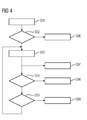
- FIG. 4 shows a flowchart for a method according to the invention.
- FIGS. 5, 6 is a temperature correction reproduced as an advantageous embodiment of the invention.
- a process fluid is sucked in by the turbo-compressor TCO via an inlet IN equipped with a throttle TH and different measuring points (for measuring T0, P1, P0) and after a compression into an outlet EX equipped with a measuring point (for the measurement of P2), continued encouraged.
- the measuring points in the inlet IN measure a suction pressure P0 before the throttle TH, an inlet pressure P1 and an intake temperature T0.
- an inlet temperature T1 can be measured in a first compressor impeller, which may differ in particular in the case of an open bypass of the intake temperature T0 of the compressor.
- the throttle TH in the inlet with the surrounding pressure measuring points can be used to determine the mass flow or volume flow.
- the inlet IN has an inlet guide IGV acting as a quantity adjusting means FC1 for the process fluid PFL entering the turbo-compressor TCO.
- the outlet EX may have an outlet guide OGV (in the FIG. 1 drawn - is to be understood only as optional), which also acts as a quantity adjustment FC1 in the outlet, at least insofar as the pressure loss in the outlet EX influenced with the Austrittsleitapparat OGV is, so that the flow rate through the turbo-compressor TCO can be effectively changed.
- the turbocompressor TCO comprises a turbocompressor rotor TCR surrounded by stator elements in the area, which is driven by a drive DRV.
- the outlet EX which leads to a compressed to the final pressure P2 process fluid PFL can be lowered in the pressure level by a bypass line BYL is opened.
- the by-pass line BYL directs the compressed process fluid PFL either into a non-illustrated pressure sink (e.g., atmosphere) via a blow-off valve VFL, or by means of the opening of a bypass valve VBY this process fluid PFL - the compression path of the turbocompressor TCO immediately - is returned to the inlet IN.
- a non-illustrated pressure sink e.g., atmosphere
- VBY blow-off valve
- a central controller CU takes the described measurements of pressure and temperature and controls the positions of the nozzles (inlet guide IGV, outlet guide OGV) the speed of the drive DRV and the position of the bypass line released and closing valves (blow-off valve VFL, bypass valve VBY) ,
- the controllable components bypass line BYL, mecanicsleitapparat IGV, Austrittsleitapparat OGV and controllable in its speed drive DRV or a speed control SPC the central control unit CU act as the first Mengenverstell respondeden FC1 for the promotion of the process fluid PFL by the turbo compressor TCO.
- the turbocompressor TCO is considered here as the entirety of the components that suck in a process fluid PFL and further promote it in a compressed manner. This includes the drive DRV and the bypass line BYL with the respectively connected components.
- the Figures 2 and 3 each show a schematic representation of a map CD for illustrating the method according to the invention for a turbocompressor TCO.
- a dimensionless characteristic number characteristic of the volume flow is plotted as a percentage of the maximum volume flow.
- the Y-axis here shows a dimensionless characteristic for the pressure increase, z.
- B. the pressure ratio (outlet pressure p2 / inlet pressure p0) in percent of the maximum pressure ratio of the turbocompressor TCO applied.
- a pumping limit SL is plotted in the characteristic map CD and a surge limit control line SCL and beyond the surge limit SL at a specific guide distance DST to the surge limit control line SCL is a distance line DSCL.
- the distance line DSCL runs essentially parallel to the pumping limit SL, wherein additional distance lines DIL between the distance line DSCL and the pumping limit SL are also plotted, which indicate the respective distance fraction part FRP for a point between the distance line DSCL and the pumping limit SL.
- the surge limit SL has a local maximum LMAX. To the left of the maximum LMAX in a first operating range OCR1, the pumping limit SL is monotonically increasing and monotonically decreasing to the right of the maximum LMAX in a second operating range OCR2.
- the representation is comparable, wherein the surge limit SL has no steady course, but instead is divided into three discontinuously interconnected operating areas OCR1, OCR2, OCR3.
- the middle local second operating area OCR2 describes a horizontal course, so that the respectively left and right located connection points of the first rising area and second falling area on this horizontal intermediate course be considered as local maxima LMAX.
- the distance line DSCL and the distance separating lines DIL and the corresponding spacing fractions FRP are identified in the region of the local maxima LMAX by concentric circles around the maxima LMAX.
- Step S01 first defines the surge limit SL. By evaluating the intake temperature T0, it is decided in S02 whether a temperature correction is necessary. If the temperature correction is necessary, it is selected in the step labeled S06 which two pumping limits SL are to be used for certain temperatures with respect to the intake temperature. If no temperature correction is necessary, the method switches to the step designated by S03, in which the current distance of the current operating point OAC to the surge limit control line SCL is determined as a vertical distance fraction FRP of the directional distance DST of the distance line DSCL to the surge limit SL. Based on this distance, it is decided in step S07 whether there is a control deviation for the surge limit controller and the control must initiate appropriate measures.
- the method changes to the step designated by S08 in which the adjustment speed TR1 in this first operating range OCR1, an increasing surge limit in the travel range OPR of a first quantity adjusting device FC1 - here of the inlet guide IGV - to a first limit value LTR1 depending on the distance fraction FRP is reduced.
- the method switches to the step designated by S05 and causes, with the subsequent method step indicated by S09, that the adjustment speed TR1 of the inlet guide IGV or a first quantity adjusting device FC1 in FIG Opening direction and a first adjustment direction TRD is reduced in dependence on the distance fraction part FRP. Subsequently the method according to the invention changes again to step S03 in order to check again for control deviations.
- a current operating point OAC, OAC 'in the FIGS. 5, 6 is shown for two cases, with surge limit control lines SCL for three different temperatures T01, T02, T03 are also shown.
- the vertical distance fraction FRP of the distance of the current operating point OAC to the surge limit SL is defined as a linear extrapolation or linear interpolation (in the FIGS. 5, 6 both shown) of the two distance fraction FRP each calculated from the current operating point OAC, OAC 'and the first and second surge limit control line SCL1, SCL2 with the respective temperature T01, T02 to the surge limits of the control lines SCL1, SC12 the current intake temperature TACT.
- FIGS. 5, 6 each differ by a with respect to the different pumping limits SL caused by different temperatures to the current operating point OAC, OAC '.
Landscapes
- Engineering & Computer Science (AREA)
- Mechanical Engineering (AREA)
- General Engineering & Computer Science (AREA)
- Physics & Mathematics (AREA)
- Geometry (AREA)
- Life Sciences & Earth Sciences (AREA)
- Sustainable Development (AREA)
- Control Of Positive-Displacement Air Blowers (AREA)
Priority Applications (1)
| Application Number | Priority Date | Filing Date | Title |
|---|---|---|---|
| EP15186293.5A EP3147511A1 (fr) | 2015-09-22 | 2015-09-22 | Procédé de contrôle de pompage, turbocompresseur |
Applications Claiming Priority (1)
| Application Number | Priority Date | Filing Date | Title |
|---|---|---|---|
| EP15186293.5A EP3147511A1 (fr) | 2015-09-22 | 2015-09-22 | Procédé de contrôle de pompage, turbocompresseur |
Publications (1)
| Publication Number | Publication Date |
|---|---|
| EP3147511A1 true EP3147511A1 (fr) | 2017-03-29 |
Family
ID=54196847
Family Applications (1)
| Application Number | Title | Priority Date | Filing Date |
|---|---|---|---|
| EP15186293.5A Withdrawn EP3147511A1 (fr) | 2015-09-22 | 2015-09-22 | Procédé de contrôle de pompage, turbocompresseur |
Country Status (1)
| Country | Link |
|---|---|
| EP (1) | EP3147511A1 (fr) |
Citations (5)
| Publication number | Priority date | Publication date | Assignee | Title |
|---|---|---|---|---|
| DE2739229A1 (de) * | 1977-08-31 | 1979-03-15 | Siemens Ag | Regeleinrichtung fuer einen turboverdichter |
| EP0175445A1 (fr) * | 1984-08-20 | 1986-03-26 | International Control Automation Finance S.A. | Contrôle de pompage pour compresseur |
| EP0757180A1 (fr) * | 1995-08-01 | 1997-02-05 | MAN Gutehoffnungshütte Aktiengesellschaft | Procédé et dispositif d'opération des turbomachines avec régulateurs à gain proportionnel élevé |
| EP0769624A1 (fr) * | 1995-10-20 | 1997-04-23 | Compressor Controls Corporation | Procédé et appareil d'équilibrage de charge entre compresseurs multiples |
| EP2476910A2 (fr) * | 2011-01-13 | 2012-07-18 | Energy Control Technologies, Inc. | Procédé et prévention de surtension dans un compresseur dynamique utilisant un système de contrôle de prévention adaptative et marge de sécurité adaptative |
-
2015
- 2015-09-22 EP EP15186293.5A patent/EP3147511A1/fr not_active Withdrawn
Patent Citations (5)
| Publication number | Priority date | Publication date | Assignee | Title |
|---|---|---|---|---|
| DE2739229A1 (de) * | 1977-08-31 | 1979-03-15 | Siemens Ag | Regeleinrichtung fuer einen turboverdichter |
| EP0175445A1 (fr) * | 1984-08-20 | 1986-03-26 | International Control Automation Finance S.A. | Contrôle de pompage pour compresseur |
| EP0757180A1 (fr) * | 1995-08-01 | 1997-02-05 | MAN Gutehoffnungshütte Aktiengesellschaft | Procédé et dispositif d'opération des turbomachines avec régulateurs à gain proportionnel élevé |
| EP0769624A1 (fr) * | 1995-10-20 | 1997-04-23 | Compressor Controls Corporation | Procédé et appareil d'équilibrage de charge entre compresseurs multiples |
| EP2476910A2 (fr) * | 2011-01-13 | 2012-07-18 | Energy Control Technologies, Inc. | Procédé et prévention de surtension dans un compresseur dynamique utilisant un système de contrôle de prévention adaptative et marge de sécurité adaptative |
Similar Documents
| Publication | Publication Date | Title |
|---|---|---|
| EP2033057B1 (fr) | Dispositif et procédé pour réaliser un essai de fonction d'organe de réglage sur une turbomachine | |
| DE2909825C2 (de) | Vorrichtung zur Einstellung des Anstellwinkels der Verdichterleitschaufeln eines Gasturbinentriebwerks | |
| DE60300765T2 (de) | Vorrichtung zur steuerung des drucks in einer prozesskammer und betriebsverfahren dafür | |
| DE102008058799A1 (de) | Verfahren zum Betrieb eines mehrstufigen Verdichters | |
| DE102012105951A1 (de) | Pumpensystem zur Evakuierung von Gas aus einer Mehrzahl von Kammern sowie Verfahren zur Steuerung des Pumpensystems | |
| WO2012013530A1 (fr) | Procédé pour faire fonctionner un compresseur | |
| EP3167197B1 (fr) | Procédé de commande de la pression et la température d'un fluide dans une série de compresseurs cryogeniques | |
| DE102007010768A1 (de) | Verfahren für die Optimierung der Ventilstellung und der Pumpendrehzahl in einem Ventilsystem mit PID-Regelung ohne die Verwendung externer Signale | |
| DE102010040503A1 (de) | Verfahren zur Steuerung eines Verdichters | |
| DE19933202B4 (de) | Verfahren zum Betreiben mehrstufiger Verdichter | |
| EP3242035B1 (fr) | Procédé de fonctionnement d'au moins un groupe motopompe parmi une pluralité de groupes motopompe | |
| DE10304063A1 (de) | Verfahren zum sicheren Betreiben von Turbokompressoren mit einer Pumpgrenzregelung und einem Pumpgrenzregelventil | |
| DE102008005354B4 (de) | Verfahren zur Regelung einer Strömungsmaschine | |
| EP3147511A1 (fr) | Procédé de contrôle de pompage, turbocompresseur | |
| DE3424024A1 (de) | Verfahren und vorrichtung zur steuerung der foerdermenge eines mehrstufigen kompressors | |
| EP3167196B1 (fr) | Procédé de régulation de la vitesse de rotation de compresseurs cryogéniques connectés en série | |
| EP3119596A1 (fr) | Dispositif pour obturer et gonfler des objets gonflables | |
| DE102014005384A1 (de) | Sauggerät und Verfahren zum Betreiben eines Sauggeräts | |
| DE102012212410A1 (de) | Paralleldiffusor für eine Fluidmaschine | |
| EP0757180A1 (fr) | Procédé et dispositif d'opération des turbomachines avec régulateurs à gain proportionnel élevé | |
| DE102015007731A1 (de) | Verfahren zum Verdichten eines Gases, Recheneinheit und mehrstufiger Kolbenverdichter | |
| WO2018054546A1 (fr) | Procédé pour faire fonctionner un turbocompresseur, turbocompresseur comportant un régulateur de limite de pompage et dispositif de séparation d'air | |
| DE102015219990A1 (de) | Verfahren zum Betreiben einer Pumpenanordnung mit einer Verstellpumpe | |
| DE102020212603A1 (de) | Verdichter und Verfahren zum Betreiben eines Verdichters | |
| AT1097U1 (de) | Verfahren und einrichtung zum regeln einer das verdichter-druckverhältnis und/oder den gasstrom durch den verdichter eines verbrennungsmotors beeinflussenden stelleinrichtung |
Legal Events
| Date | Code | Title | Description |
|---|---|---|---|
| PUAI | Public reference made under article 153(3) epc to a published international application that has entered the european phase |
Free format text: ORIGINAL CODE: 0009012 |
|
| AK | Designated contracting states |
Kind code of ref document: A1 Designated state(s): AL AT BE BG CH CY CZ DE DK EE ES FI FR GB GR HR HU IE IS IT LI LT LU LV MC MK MT NL NO PL PT RO RS SE SI SK SM TR |
|
| AX | Request for extension of the european patent |
Extension state: BA ME |
|
| RAP1 | Party data changed (applicant data changed or rights of an application transferred) |
Owner name: SIEMENS AKTIENGESELLSCHAFT |
|
| STAA | Information on the status of an ep patent application or granted ep patent |
Free format text: STATUS: THE APPLICATION IS DEEMED TO BE WITHDRAWN |
|
| 18D | Application deemed to be withdrawn |
Effective date: 20170930 |