EP3147492B1 - Ethanol engine system - Google Patents
Ethanol engine system Download PDFInfo
- Publication number
- EP3147492B1 EP3147492B1 EP15796852.0A EP15796852A EP3147492B1 EP 3147492 B1 EP3147492 B1 EP 3147492B1 EP 15796852 A EP15796852 A EP 15796852A EP 3147492 B1 EP3147492 B1 EP 3147492B1
- Authority
- EP
- European Patent Office
- Prior art keywords
- engine
- reformer
- supplied
- ethanol
- solution
- Prior art date
- Legal status (The legal status is an assumption and is not a legal conclusion. Google has not performed a legal analysis and makes no representation as to the accuracy of the status listed.)
- Active
Links
- LFQSCWFLJHTTHZ-UHFFFAOYSA-N Ethanol Chemical compound CCO LFQSCWFLJHTTHZ-UHFFFAOYSA-N 0.000 title claims description 389
- 238000011084 recovery Methods 0.000 claims description 95
- 238000002485 combustion reaction Methods 0.000 claims description 61
- 239000000446 fuel Substances 0.000 claims description 58
- XLYOFNOQVPJJNP-UHFFFAOYSA-N water Chemical compound O XLYOFNOQVPJJNP-UHFFFAOYSA-N 0.000 claims description 55
- 239000007788 liquid Substances 0.000 claims description 13
- 238000001816 cooling Methods 0.000 claims description 11
- 239000002826 coolant Substances 0.000 claims description 8
- 239000000243 solution Substances 0.000 description 152
- 239000007789 gas Substances 0.000 description 113
- 238000006243 chemical reaction Methods 0.000 description 37
- 230000014509 gene expression Effects 0.000 description 23
- 229910052739 hydrogen Inorganic materials 0.000 description 18
- 239000001257 hydrogen Substances 0.000 description 18
- 238000000034 method Methods 0.000 description 18
- 230000002829 reductive effect Effects 0.000 description 15
- UGFAIRIUMAVXCW-UHFFFAOYSA-N Carbon monoxide Chemical compound [O+]#[C-] UGFAIRIUMAVXCW-UHFFFAOYSA-N 0.000 description 14
- 229910002091 carbon monoxide Inorganic materials 0.000 description 14
- 238000006057 reforming reaction Methods 0.000 description 14
- 239000003054 catalyst Substances 0.000 description 13
- UFHFLCQGNIYNRP-UHFFFAOYSA-N Hydrogen Chemical compound [H][H] UFHFLCQGNIYNRP-UHFFFAOYSA-N 0.000 description 11
- 230000000694 effects Effects 0.000 description 11
- 239000000463 material Substances 0.000 description 11
- 238000002407 reforming Methods 0.000 description 10
- 239000004071 soot Substances 0.000 description 10
- 239000011888 foil Substances 0.000 description 7
- 150000002431 hydrogen Chemical class 0.000 description 7
- 229910052751 metal Inorganic materials 0.000 description 7
- 239000002184 metal Substances 0.000 description 7
- 239000003921 oil Substances 0.000 description 7
- OKTJSMMVPCPJKN-UHFFFAOYSA-N Carbon Chemical compound [C] OKTJSMMVPCPJKN-UHFFFAOYSA-N 0.000 description 6
- 229910052799 carbon Inorganic materials 0.000 description 6
- 239000000295 fuel oil Substances 0.000 description 6
- 230000001965 increasing effect Effects 0.000 description 6
- 239000002551 biofuel Substances 0.000 description 5
- 239000000498 cooling water Substances 0.000 description 5
- 238000010438 heat treatment Methods 0.000 description 5
- CURLTUGMZLYLDI-UHFFFAOYSA-N Carbon dioxide Chemical compound O=C=O CURLTUGMZLYLDI-UHFFFAOYSA-N 0.000 description 4
- 238000009835 boiling Methods 0.000 description 4
- 230000007423 decrease Effects 0.000 description 4
- 230000002708 enhancing effect Effects 0.000 description 4
- 238000001704 evaporation Methods 0.000 description 4
- 230000008020 evaporation Effects 0.000 description 4
- 239000002828 fuel tank Substances 0.000 description 4
- YXFVVABEGXRONW-UHFFFAOYSA-N Toluene Chemical compound CC1=CC=CC=C1 YXFVVABEGXRONW-UHFFFAOYSA-N 0.000 description 3
- 229910002092 carbon dioxide Inorganic materials 0.000 description 3
- 239000001569 carbon dioxide Substances 0.000 description 3
- 230000018044 dehydration Effects 0.000 description 3
- 238000006297 dehydration reaction Methods 0.000 description 3
- 230000006866 deterioration Effects 0.000 description 3
- 239000007924 injection Substances 0.000 description 3
- 238000002347 injection Methods 0.000 description 3
- 238000004519 manufacturing process Methods 0.000 description 3
- VNWKTOKETHGBQD-UHFFFAOYSA-N methane Chemical compound C VNWKTOKETHGBQD-UHFFFAOYSA-N 0.000 description 3
- 239000000203 mixture Substances 0.000 description 3
- 230000036961 partial effect Effects 0.000 description 3
- 230000001105 regulatory effect Effects 0.000 description 3
- 238000000926 separation method Methods 0.000 description 3
- 229910000838 Al alloy Inorganic materials 0.000 description 2
- QGZKDVFQNNGYKY-UHFFFAOYSA-N Ammonia Chemical compound N QGZKDVFQNNGYKY-UHFFFAOYSA-N 0.000 description 2
- 239000002028 Biomass Substances 0.000 description 2
- 239000004215 Carbon black (E152) Substances 0.000 description 2
- XEEYBQQBJWHFJM-UHFFFAOYSA-N Iron Chemical compound [Fe] XEEYBQQBJWHFJM-UHFFFAOYSA-N 0.000 description 2
- PXHVJJICTQNCMI-UHFFFAOYSA-N Nickel Chemical compound [Ni] PXHVJJICTQNCMI-UHFFFAOYSA-N 0.000 description 2
- KDLHZDBZIXYQEI-UHFFFAOYSA-N Palladium Chemical compound [Pd] KDLHZDBZIXYQEI-UHFFFAOYSA-N 0.000 description 2
- MCMNRKCIXSYSNV-UHFFFAOYSA-N Zirconium dioxide Chemical compound O=[Zr]=O MCMNRKCIXSYSNV-UHFFFAOYSA-N 0.000 description 2
- 239000007864 aqueous solution Substances 0.000 description 2
- 230000006835 compression Effects 0.000 description 2
- 238000007906 compression Methods 0.000 description 2
- 230000001276 controlling effect Effects 0.000 description 2
- 238000010790 dilution Methods 0.000 description 2
- 239000012895 dilution Substances 0.000 description 2
- 239000012530 fluid Substances 0.000 description 2
- 239000003502 gasoline Substances 0.000 description 2
- 239000000383 hazardous chemical Substances 0.000 description 2
- 229930195733 hydrocarbon Natural products 0.000 description 2
- 150000002430 hydrocarbons Chemical class 0.000 description 2
- 239000003208 petroleum Substances 0.000 description 2
- BASFCYQUMIYNBI-UHFFFAOYSA-N platinum Chemical compound [Pt] BASFCYQUMIYNBI-UHFFFAOYSA-N 0.000 description 2
- IKHGUXGNUITLKF-UHFFFAOYSA-N Acetaldehyde Chemical compound CC=O IKHGUXGNUITLKF-UHFFFAOYSA-N 0.000 description 1
- VYZAMTAEIAYCRO-UHFFFAOYSA-N Chromium Chemical compound [Cr] VYZAMTAEIAYCRO-UHFFFAOYSA-N 0.000 description 1
- RYGMFSIKBFXOCR-UHFFFAOYSA-N Copper Chemical compound [Cu] RYGMFSIKBFXOCR-UHFFFAOYSA-N 0.000 description 1
- 229910001141 Ductile iron Inorganic materials 0.000 description 1
- 229910000861 Mg alloy Inorganic materials 0.000 description 1
- ZOKXTWBITQBERF-UHFFFAOYSA-N Molybdenum Chemical compound [Mo] ZOKXTWBITQBERF-UHFFFAOYSA-N 0.000 description 1
- KJTLSVCANCCWHF-UHFFFAOYSA-N Ruthenium Chemical compound [Ru] KJTLSVCANCCWHF-UHFFFAOYSA-N 0.000 description 1
- 240000000111 Saccharum officinarum Species 0.000 description 1
- 235000007201 Saccharum officinarum Nutrition 0.000 description 1
- 240000008042 Zea mays Species 0.000 description 1
- 235000005824 Zea mays ssp. parviglumis Nutrition 0.000 description 1
- 235000002017 Zea mays subsp mays Nutrition 0.000 description 1
- HCHKCACWOHOZIP-UHFFFAOYSA-N Zinc Chemical compound [Zn] HCHKCACWOHOZIP-UHFFFAOYSA-N 0.000 description 1
- 230000005856 abnormality Effects 0.000 description 1
- 229910052782 aluminium Inorganic materials 0.000 description 1
- XAGFODPZIPBFFR-UHFFFAOYSA-N aluminium Chemical compound [Al] XAGFODPZIPBFFR-UHFFFAOYSA-N 0.000 description 1
- PNEYBMLMFCGWSK-UHFFFAOYSA-N aluminium oxide Inorganic materials [O-2].[O-2].[O-2].[Al+3].[Al+3] PNEYBMLMFCGWSK-UHFFFAOYSA-N 0.000 description 1
- 229910021529 ammonia Inorganic materials 0.000 description 1
- 239000003225 biodiesel Substances 0.000 description 1
- 230000003197 catalytic effect Effects 0.000 description 1
- 229910052804 chromium Inorganic materials 0.000 description 1
- 239000011651 chromium Substances 0.000 description 1
- 239000011248 coating agent Substances 0.000 description 1
- 238000000576 coating method Methods 0.000 description 1
- 229910017052 cobalt Inorganic materials 0.000 description 1
- 239000010941 cobalt Substances 0.000 description 1
- GUTLYIVDDKVIGB-UHFFFAOYSA-N cobalt atom Chemical compound [Co] GUTLYIVDDKVIGB-UHFFFAOYSA-N 0.000 description 1
- 238000004939 coking Methods 0.000 description 1
- 239000002131 composite material Substances 0.000 description 1
- 229910052802 copper Inorganic materials 0.000 description 1
- 239000010949 copper Substances 0.000 description 1
- 235000005822 corn Nutrition 0.000 description 1
- 238000000354 decomposition reaction Methods 0.000 description 1
- 230000003247 decreasing effect Effects 0.000 description 1
- 238000006356 dehydrogenation reaction Methods 0.000 description 1
- 238000001514 detection method Methods 0.000 description 1
- 238000010586 diagram Methods 0.000 description 1
- 239000003085 diluting agent Substances 0.000 description 1
- IDGUHHHQCWSQLU-UHFFFAOYSA-N ethanol;hydrate Chemical compound O.CCO IDGUHHHQCWSQLU-UHFFFAOYSA-N 0.000 description 1
- 238000000855 fermentation Methods 0.000 description 1
- 230000004151 fermentation Effects 0.000 description 1
- 230000002401 inhibitory effect Effects 0.000 description 1
- 230000000977 initiatory effect Effects 0.000 description 1
- 229910052741 iridium Inorganic materials 0.000 description 1
- GKOZUEZYRPOHIO-UHFFFAOYSA-N iridium atom Chemical compound [Ir] GKOZUEZYRPOHIO-UHFFFAOYSA-N 0.000 description 1
- 229910052742 iron Inorganic materials 0.000 description 1
- 229910052750 molybdenum Inorganic materials 0.000 description 1
- 239000011733 molybdenum Substances 0.000 description 1
- 239000003345 natural gas Substances 0.000 description 1
- 230000007935 neutral effect Effects 0.000 description 1
- 229910052759 nickel Inorganic materials 0.000 description 1
- 229910052758 niobium Inorganic materials 0.000 description 1
- 239000010955 niobium Substances 0.000 description 1
- GUCVJGMIXFAOAE-UHFFFAOYSA-N niobium atom Chemical compound [Nb] GUCVJGMIXFAOAE-UHFFFAOYSA-N 0.000 description 1
- 229910000484 niobium oxide Inorganic materials 0.000 description 1
- URLJKFSTXLNXLG-UHFFFAOYSA-N niobium(5+);oxygen(2-) Chemical compound [O-2].[O-2].[O-2].[O-2].[O-2].[Nb+5].[Nb+5] URLJKFSTXLNXLG-UHFFFAOYSA-N 0.000 description 1
- TVMXDCGIABBOFY-UHFFFAOYSA-N octane Chemical compound CCCCCCCC TVMXDCGIABBOFY-UHFFFAOYSA-N 0.000 description 1
- 229910052762 osmium Inorganic materials 0.000 description 1
- SYQBFIAQOQZEGI-UHFFFAOYSA-N osmium atom Chemical compound [Os] SYQBFIAQOQZEGI-UHFFFAOYSA-N 0.000 description 1
- RVTZCBVAJQQJTK-UHFFFAOYSA-N oxygen(2-);zirconium(4+) Chemical compound [O-2].[O-2].[Zr+4] RVTZCBVAJQQJTK-UHFFFAOYSA-N 0.000 description 1
- 229910052763 palladium Inorganic materials 0.000 description 1
- 229910052697 platinum Inorganic materials 0.000 description 1
- 239000011148 porous material Substances 0.000 description 1
- 229910052702 rhenium Inorganic materials 0.000 description 1
- WUAPFZMCVAUBPE-UHFFFAOYSA-N rhenium atom Chemical compound [Re] WUAPFZMCVAUBPE-UHFFFAOYSA-N 0.000 description 1
- 229910052703 rhodium Inorganic materials 0.000 description 1
- 239000010948 rhodium Substances 0.000 description 1
- MHOVAHRLVXNVSD-UHFFFAOYSA-N rhodium atom Chemical compound [Rh] MHOVAHRLVXNVSD-UHFFFAOYSA-N 0.000 description 1
- 229910052707 ruthenium Inorganic materials 0.000 description 1
- 238000007086 side reaction Methods 0.000 description 1
- 230000000087 stabilizing effect Effects 0.000 description 1
- WFKWXMTUELFFGS-UHFFFAOYSA-N tungsten Chemical compound [W] WFKWXMTUELFFGS-UHFFFAOYSA-N 0.000 description 1
- 229910052721 tungsten Inorganic materials 0.000 description 1
- 239000010937 tungsten Substances 0.000 description 1
- 229910052720 vanadium Inorganic materials 0.000 description 1
- LEONUFNNVUYDNQ-UHFFFAOYSA-N vanadium atom Chemical compound [V] LEONUFNNVUYDNQ-UHFFFAOYSA-N 0.000 description 1
- 229910052725 zinc Inorganic materials 0.000 description 1
- 239000011701 zinc Substances 0.000 description 1
- 229910001928 zirconium oxide Inorganic materials 0.000 description 1
Images


Classifications
-
- F—MECHANICAL ENGINEERING; LIGHTING; HEATING; WEAPONS; BLASTING
- F02—COMBUSTION ENGINES; HOT-GAS OR COMBUSTION-PRODUCT ENGINE PLANTS
- F02M—SUPPLYING COMBUSTION ENGINES IN GENERAL WITH COMBUSTIBLE MIXTURES OR CONSTITUENTS THEREOF
- F02M27/00—Apparatus for treating combustion-air, fuel, or fuel-air mixture, by catalysts, electric means, magnetism, rays, sound waves, or the like
- F02M27/02—Apparatus for treating combustion-air, fuel, or fuel-air mixture, by catalysts, electric means, magnetism, rays, sound waves, or the like by catalysts
-
- C—CHEMISTRY; METALLURGY
- C01—INORGANIC CHEMISTRY
- C01B—NON-METALLIC ELEMENTS; COMPOUNDS THEREOF; METALLOIDS OR COMPOUNDS THEREOF NOT COVERED BY SUBCLASS C01C
- C01B3/00—Hydrogen; Gaseous mixtures containing hydrogen; Separation of hydrogen from mixtures containing it; Purification of hydrogen
- C01B3/02—Production of hydrogen or of gaseous mixtures containing a substantial proportion of hydrogen
- C01B3/32—Production of hydrogen or of gaseous mixtures containing a substantial proportion of hydrogen by reaction of gaseous or liquid organic compounds with gasifying agents, e.g. water, carbon dioxide, air
- C01B3/323—Catalytic reaction of gaseous or liquid organic compounds other than hydrocarbons with gasifying agents
-
- C—CHEMISTRY; METALLURGY
- C01—INORGANIC CHEMISTRY
- C01B—NON-METALLIC ELEMENTS; COMPOUNDS THEREOF; METALLOIDS OR COMPOUNDS THEREOF NOT COVERED BY SUBCLASS C01C
- C01B3/00—Hydrogen; Gaseous mixtures containing hydrogen; Separation of hydrogen from mixtures containing it; Purification of hydrogen
- C01B3/50—Separation of hydrogen or hydrogen containing gases from gaseous mixtures, e.g. purification
-
- F—MECHANICAL ENGINEERING; LIGHTING; HEATING; WEAPONS; BLASTING
- F02—COMBUSTION ENGINES; HOT-GAS OR COMBUSTION-PRODUCT ENGINE PLANTS
- F02B—INTERNAL-COMBUSTION PISTON ENGINES; COMBUSTION ENGINES IN GENERAL
- F02B9/00—Engines characterised by other types of ignition
- F02B9/02—Engines characterised by other types of ignition with compression ignition
-
- F—MECHANICAL ENGINEERING; LIGHTING; HEATING; WEAPONS; BLASTING
- F02—COMBUSTION ENGINES; HOT-GAS OR COMBUSTION-PRODUCT ENGINE PLANTS
- F02D—CONTROLLING COMBUSTION ENGINES
- F02D19/00—Controlling engines characterised by their use of non-liquid fuels, pluralities of fuels, or non-fuel substances added to the combustible mixtures
- F02D19/06—Controlling engines characterised by their use of non-liquid fuels, pluralities of fuels, or non-fuel substances added to the combustible mixtures peculiar to engines working with pluralities of fuels, e.g. alternatively with light and heavy fuel oil, other than engines indifferent to the fuel consumed
- F02D19/08—Controlling engines characterised by their use of non-liquid fuels, pluralities of fuels, or non-fuel substances added to the combustible mixtures peculiar to engines working with pluralities of fuels, e.g. alternatively with light and heavy fuel oil, other than engines indifferent to the fuel consumed simultaneously using pluralities of fuels
- F02D19/082—Premixed fuels, i.e. emulsions or blends
-
- F—MECHANICAL ENGINEERING; LIGHTING; HEATING; WEAPONS; BLASTING
- F02—COMBUSTION ENGINES; HOT-GAS OR COMBUSTION-PRODUCT ENGINE PLANTS
- F02D—CONTROLLING COMBUSTION ENGINES
- F02D41/00—Electrical control of supply of combustible mixture or its constituents
- F02D41/02—Circuit arrangements for generating control signals
-
- C—CHEMISTRY; METALLURGY
- C01—INORGANIC CHEMISTRY
- C01B—NON-METALLIC ELEMENTS; COMPOUNDS THEREOF; METALLOIDS OR COMPOUNDS THEREOF NOT COVERED BY SUBCLASS C01C
- C01B2203/00—Integrated processes for the production of hydrogen or synthesis gas
- C01B2203/02—Processes for making hydrogen or synthesis gas
- C01B2203/0205—Processes for making hydrogen or synthesis gas containing a reforming step
- C01B2203/0227—Processes for making hydrogen or synthesis gas containing a reforming step containing a catalytic reforming step
- C01B2203/0233—Processes for making hydrogen or synthesis gas containing a reforming step containing a catalytic reforming step the reforming step being a steam reforming step
-
- C—CHEMISTRY; METALLURGY
- C01—INORGANIC CHEMISTRY
- C01B—NON-METALLIC ELEMENTS; COMPOUNDS THEREOF; METALLOIDS OR COMPOUNDS THEREOF NOT COVERED BY SUBCLASS C01C
- C01B2203/00—Integrated processes for the production of hydrogen or synthesis gas
- C01B2203/04—Integrated processes for the production of hydrogen or synthesis gas containing a purification step for the hydrogen or the synthesis gas
- C01B2203/046—Purification by cryogenic separation
-
- C—CHEMISTRY; METALLURGY
- C01—INORGANIC CHEMISTRY
- C01B—NON-METALLIC ELEMENTS; COMPOUNDS THEREOF; METALLOIDS OR COMPOUNDS THEREOF NOT COVERED BY SUBCLASS C01C
- C01B2203/00—Integrated processes for the production of hydrogen or synthesis gas
- C01B2203/12—Feeding the process for making hydrogen or synthesis gas
- C01B2203/1205—Composition of the feed
- C01B2203/1211—Organic compounds or organic mixtures used in the process for making hydrogen or synthesis gas
- C01B2203/1217—Alcohols
- C01B2203/1229—Ethanol
-
- C—CHEMISTRY; METALLURGY
- C01—INORGANIC CHEMISTRY
- C01B—NON-METALLIC ELEMENTS; COMPOUNDS THEREOF; METALLOIDS OR COMPOUNDS THEREOF NOT COVERED BY SUBCLASS C01C
- C01B2203/00—Integrated processes for the production of hydrogen or synthesis gas
- C01B2203/14—Details of the flowsheet
- C01B2203/148—Details of the flowsheet involving a recycle stream to the feed of the process for making hydrogen or synthesis gas
Definitions
- the present invention relates to an ethanol engine system that uses ethanol for fuel.
- Ethanol can be acquired from biomass such as a sugar cane and a corn as so-called biofuel. Such carbon neutral ethanol can reduce carbon dioxide (CO 2 ) by being replaced with petroleum fuel.
- CO 2 carbon dioxide
- the market price of ethanol is higher than that of petroleum fuel and it hinders the popularization of ethanol as fuel.
- a manufacturing process of ethanol originated from biomass is roughly classified into a saccharification process, a fermentation process and a dehydration process. Predetermined energy is required to execute each process. However, out of these processes, the dehydration process requires approximately 25% of the whole energy required for the manufacturing process. Accordingly, if an aqueous ethanol solution can be utilized for fuel as it is without using the dehydration process, an amount of energy required for a manufacturing process of alcohol can be reduced and a price of ethanol can be kept down.
- Patent Literature 1 discloses an ethanol engine system in which an aqueous ethanol solution reserved in a reservoir tank is directly injected into a combustion chamber of an engine, a reformed gas generated in a reformer using the aqueous ethanol solution for material is supplied to the engine and motive power is generated by combusting ethanol included in the aqueous ethanol solution and the reformed gas in the combustion chamber.
- the aqueous ethanol solution is fuel suitable for the exhaust heat recovery system because the reformed gas including hydrogen can be generated from the aqueous ethanol solution by an endothermic reaction by utilizing its exhaust heat.
- hydrous ethanol has a great latent heat of evaporation to its calorific value
- the inside of the combustion chamber can be cooled by directly supplying the hydrous ethanol to the engine.
- a quantity of heat that escapes in a cooling water for the engine can be reduced and the efficiency of the system can be enhanced by increasing energy by exhaust heat for shaft power.
- Patent Literature 1 Japanese Unexamined Patent Application Publication No. 2013-204572 In WO 2011/002722 A1 , an internal combustion engine power system that utilizes a reformed alcohol fuel is described.
- the internal combustion engine power system includes dilution of the intake fluid mixture introduced into the combustion chamber or cylinder of the engine using a recirculated exhaust gas and/or excess combustion air as the diluent.
- JP 2007 056813 A a fuel supply apparatus for supplying fuel to an internal combustion engine is described.
- a mixed fuel tank and a water tank are suggested, wherein mixed fuel reforming means are positioned downstream of a mixed fuel flow passage.
- Patent Literature 1 a configuration that a reformed gas fed from the reformer and an unreformed aqueous ethanol solution are separated in a separator and the separated aqueous ethanol solution is returned to the reservoir tank again is adopted. Therefore, as an ethanol concentration of a hydrous ethanol in the reservoir tank lowers, a calorific value of ethanol supplied to the engine, components of the reformed gas generated in the reformer and an endothermic energy amount in reforming are labile, and deterioration of a thermal efficiency is caused.
- Patent Literature 1 an ethanol concentration sensor is provided to the reservoir tank so as to manage the concentration of ethanol, although Patent Literature 1 has a problem that control corresponding to variation of the ethanol concentration is required, the control and the system are made intricate and driving is limited by the variation of the ethanol concentration.
- an object of the present invention is to stabilize the components of the reformed gas generated by a reformer and a calorific value of fuel supplied to an engine and to provide an ethanol engine system having a high thermal efficiency.
- the ethanol engine system that stabilizes components of the reformed gas generated in the reformer and a calorific value of fuel supplied to the engine and has a high thermal efficiency can be provided.
- An ethanol engine system equivalent to this embodiment generates a motive power by supplying a reformed gas acquired by using ethanol for a carbon source and an aqueous ethanol solution to an engine.
- the configuration of the ethanol engine system, reforming materials and the aqueous ethanol solution used for fuel and the operation of the ethanol engine system will be described below.
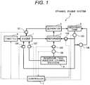
- Fig. 1 illustrates the configuration of the ethanol engine system according to this embodiment of the present invention.
- the ethanol engine system S equivalent to this embodiment is configured by a reservoir tank 4 that reserves an aqueous ethanol solution, an engine 1, a reformer 2, a separator 3, a recovery tank 5 and a controller 7.
- the aqueous ethanol solution is supplied to the engine 1 from the reservoir tank 4 by a second supply device 107 as shown in Fig. 1 and a reformed gas from the reformer 2 is supplied to the engine 1 via the separator 3 and a reformed gas supply device 101.
- the engine 1 generates motive power by the combustion of ethanol included in the aqueous ethanol solution and the reformed gas.
- the reformed gas generated by reforming reaction by using the aqueous ethanol solution supplied from the reservoir tank 4 via the first supply device 103 for material and a mixed gas including ethanol vapor which is an unreacted component and water vapor are generated.
- the mixed gas generated in the reformer 2 is fed to the separator 3, the water vapor included in the mixed gas is condensed, the reformed gas, the ethanol vapor and water are separated into gas and liquid there, and the reformed gas and the ethanol vapor are supplied to the engine 1 via the reformed gas supply device 101.
- recovery solution concentrated water
- the ethanol engine system S in this embodiment has a characteristic that the recovery solution collected in the recovery tank 5 is respectively supplied to the reformer 2 and a combustion chamber of the engine 1 via a first recovery solution supply device 102 and a second recovery solution supply device 104.
- the concentration of the aqueous ethanol solution in the reservoir tank 4 never varies by adopting the configuration that the recovery solution separated in the separator 2 is collected in the reservoir tank 5 as described above and is supplied to the reformer 2 or the combustion chamber of the engine 1, control corresponding to the variation of the ethanol concentration in the reservoir tank 4 is not required, and the system can be simplified.
- the operation of the engine 1 is not restricted by the variation of the ethanol concentration in the reservoir tank 4.
- components of the reformed gas can be stably generated in the reformer 2 by adopting a configuration that the recovery solution in the recovery tank 5 is supplied to the reformer 2, the concentration of hydrogen in the reformed gas can be kept high, and effect for enhancing system efficiency thereby is acquired.
- water-rich liquid can be supplied to the combustion chamber of the engine 1 by adopting the configuration that the recovery solution in the recovery tank 5 is supplied to the combustion chamber of the engine 1, thereby, cooling loss of the engine is reduced, and effect for enhancing thermal efficiency is acquired.
- remarkable effect is acquired by applying the configuration to an engine in which a heat shield is built in the combustion chamber of the engine.
- the temperature of a working medium in a cylinder can be lowered by the latent heat of evaporation of the water-rich liquid by directly supplying the water-rich liquid to the combustion chamber and anti-knocking performance is enhanced. Furthermore, since the anti-knocking performance is also chemically high because ethanol is high octane number fuel, high compression ratio combustion can be realized and the high-efficiency system can be realized.
- the ethanol engine system S shown in Fig. 1 has the configuration that the recovery solution can be supplied to both the reformer 2 and the combustion chamber of the engine 1 from the recovery tank 5.
- the ethanol engine system S may also have a configuration that the recovery solution is supplied to only either the reformer 2 or the combustion chamber of the engine 1.
- Well-known supply means such as an injector and a pump is applied to the first and second supply devices 103, 107, the reformed gas supply device 101, the first and second recovery solution supply devices 102, 104, and a supplied amount, supplied pressure and others are controlled by the controller 7.
- Fig. 2 is a partial enlarged view schematically showing the vicinity of a cylinder head of the engine used in the ethanol engine system according to this embodiment.
- the engine 1 is provided with a piston 11 reciprocated in the cylinder, and an intake pipe 13 and an exhaust pipe 14 are connected to the combustion chamber 12 in the cylinder.
- the second supply device 107 for supplying the aqueous ethanol solution to the engine is attached to the intake pipe 13. It should be noted that the second supply device 107 for supplying the aqueous ethanol solution to the engine may also have a structure for directly injecting the aqueous ethanol solution into the combustion chamber of the engine. Hereby, a structure that water-rich liquid is supplied to the engine and the engine can be cooled from the inside of the combustion chamber is acquired.
- the reformed gas supply device 101 for supplying the reformed gas fed from the separator 3 to the engine is attached to the intake pipe 13 and the reformed gas is supplied to the engine together with intake air.
- the second recovery solution supply device 102 for supplying recovery solution in the recovery tank 5 to the combustion chamber of the engine 1 is connected to the combustion chamber of the engine 1. The quantity of solution required for cooling the inside of the combustion chamber can be secured by directly supplying recovery solution to the combustion chamber of the engine 1 from the second recovery solution supply device 102 even if a relatively high-concentration aqueous ethanol solution is used.
- the piston 11 it is desirable that materials low in thermal conductivity are used for the piston 11 and for example, SUS304, ductile iron, a magnesium alloy and others are used. Further, composite material acquired by coating a surface of base material such as an aluminum alloy and irony material with a zirconia film and others may also be used.
- the combustion chamber of the engine can be effectively shielded from heat by using such low-thermal conductivity piston material and directly supplying water-rich liquid to the combustion chamber and the cooling loss of the engine can be reduced.
- the aqueous ethanol solution is supplied to the reformer 2 from the reservoir tank 4 via the first supply device 103 and exhaust gas is supplied to the reformer from the engine 1.
- the reformer 2 generates the reformed gas using the aqueous ethanol solution for material.
- recovery solution can be supplied to the reformer 2 from the recovery tank 5 via the first recovery solution supply device 102.
- the reformer 2 is warmed up by exhaust gas from the engine 1 and generates the reformed gas having carbon monoxide and hydrogen as principal components by exchanging heat with the aqueous ethanol solution. Reforming reaction is shown in the following expression (1). C 2 H 5 OH + H 2 O (aqueous ethanol solution) ⁇ 2CO + 4H 2 (reformed gas) - 298 kJ --- Expression (1)
- the reaction that reforms the aqueous ethanol solution to carbon monoxide (CO) and hydrogen (H 2 ) is endothermic reaction and energy of 298 kJ is absorbed by reforming ethanol (C 2 H 5 OH) of 1 mol.
- the lower heating value of ethanol of 1 mol is 1235 kJ, when the reforming reaction in the expression (1) is all performed, the lower heating value of the reformed gas is 1533 kJ, and the lower heating value is enhanced by 1.24 times. Exhaust heat is recovered for energy of fuel by performing this reaction utilizing engine exhaust heat and consequently, the efficiency of the system is enhanced.
- the quantity of the aqueous ethanol solution supplied to the reformer 2 is adjusted according to the temperature and the pressure of the reformer 2, however, if only the quantity can be adjusted in a range in which the quantity set according to required torque and others of the engine 1 of the reformed gas injected from the reformed gas supply device 101 can be secured, the quantity of the aqueous ethanol solution supplied to the reformer 2 is not especially limited.
- reforming temperature of ethanol is lower, compared with that of another gasoline and fuel such as toluene and is approximately 250 to 500oC. Accordingly, a criterion for judgment on terminating a warming-up process of the reformer by exhaust gas of the engine in this embodiment can be set to the temperature of approximately 250 to 500°C of a reaction cell 31 (see Fig. 3(a) ) described later of the reformer for example. Besides, as for injection control over the reformed gas supply device 101, the temperature of approximately 250 to 500°C of the reaction cell 31 can also be used for a criterion.
- Fig. 3(a) referred next is a sectional view showing the reformer used in the ethanol engine system according to this embodiment of the present invention
- Fig. 3(b) is a sectional view showing the reaction cell built in the reformer
- Fig. 3(c) is a sectional view showing a reaction sheet built in the reaction cell.
- the reformer is provided with plural reaction cells 31 having a cylindrical outline and a cylindrical first casing 32 housing the plural reaction cells 31.
- the reformer is configured so that the aqueous ethanol solution in the reservoir tank 4 flows through each reaction cell 31. Besides, the reformer is configured so that high-temperature exhaust gas exhausted via the exhaust pipe 14 (see Fig. 2 ) of the engine 1 flows outside the reaction cell 31 and inside the first casing 32.
- the first casing 32 and a second casing 34 to be described later are made of metal such as SUS to raise their thermal conductivity.
- a shape of the first casing 32 and the second casing 34 is not limited to a cylindrical shape and in addition, for example, they may also be square cylindrical or polygonal cylindrical.
- the reaction cell 31 is provided with laminated plural reaction sheets 33 and the second casing 34 housing the plural reaction sheets 33 as shown in Fig. 3(b) .
- Each reaction sheet 33 is provided with metal foil 35 which is base material, porous layers 36 formed on both surfaces of the metal foil 35 and catalysts 37 carried in the porous layer 36 as shown in Fig. 3(c) .
- each reaction sheet 33 has a three-layer structure in which the porous layer 36 carrying the catalysts 37, the metal foil 35 and the porous layer 36 carrying the catalysts 37 are laminated in their order.
- reaction sheet 33 As the reaction sheet 33 is thin, its heat capacity is small, heat is promptly conducted in the reaction sheet 33 and promptly raises temperature up to temperature at which the catalyst 37 satisfactorily fulfills its catalytic function.
- the metal foil 35 is made of aluminum foil for example and the thickness is set to approximately 50 to 200 ⁇ m.
- the whole reaction sheet 33 may also have a porous structure not provided with the metal foil 35 or provided with a porous layer which is base material in place of the metal foil 35.
- the porous layer 36 is a layer for carrying the catalysts 37 and is provided with plural pores through which the aqueous ethanol solution, generated hydrogen (H 2 ) and generated carbon monoxide (CO) can flow.
- the above-mentioned porous layer 36 is made of oxide mainly composed of alumina, niobium oxide and zirconium oxide for example.
- the catalyst 37 is a catalyst for decomposing the aqueous ethanol solution and generating the reformed gas (hydrogen and carbon monoxide) as shown in the above-mentioned expression (1).
- the catalyst 37 described above is composed of at least one selected out of platinum, nickel, palladium, rhodium, iridium, ruthenium, molybdenum, rhenium, tungsten, vanadium, osmium, chromium, cobalt, iron, niobium, copper, zinc and others.
- the separator 3 cools the mixed gas including the reformed gas fed from the reformer 2 and separates water from the reformed gas and ethanol vapor by vapor-liquid separation by condensing water vapor including the mixed gas. Ethanol vapor which is an unreacted component and water vapor may intermingle in the gas generated in the reformer 2.
- water vapor which is an unreacted component is supplied to the engine 1 together with the reformed gas, combustion efficiency is deteriorated. Therefore, water vapor is liquefied by the separator 3 and is collected in the recovery tank 5.
- the temperature of the mixed gas emitted from the separator 3 is controlled to be higher than 78oC which is a boiling point of ethanol and to be below 100oC which is a boiling point of water.
- a high-concentration water can be collected as a recovery solution from the mixed gas in the separator 3.
- the recovery solution is water or an aqueous solution having water as a principal component.
- the aqueous solution is concretely an aqueous ethanol solution, the concentration of ethanol can be made equal to or below 10 wt%, and it is desirable that the concentration is as low as possible.
- the separator 3 may also have a structure for exchanging heat with cooling water for the engine 1 or a structure for exchanging heat between gas generated in the reformer 2 and the aqueous ethanol solution supplied to the reformer 2.
- a structure for exchanging heat between gas generated in the reformer 2 and the aqueous ethanol solution supplied to the reformer 2 supplied to the reformer 2.
- cooling heat of gas generated in the reformer 2 can be utilized for heating hydrous ethanol
- an amount for heating the aqueous ethanol solution can be reduced. Consequently, a calorific value used for reforming reaction in the reformer 2 can be increased.
- the recovery solution collected in the recovery tank is pressurized by a pump 105 and is supplied to the reformer 2 by the first recovery solution supply device 102 again.
- the reason why the recovery solution is supplied to the reformer 2 again is as follows.
- the reforming reaction of the aqueous ethanol solution in the expression (1) meets a stoichiometry when ethanol and water have the same number of moles.
- the reason is that as the number of moles of water is close to the stoichiometry, carbon is educed on a surface of the catalyst, the activity of the catalyst is readily deteriorated and consequently, a conversion ratio from the aqueous ethanol solution to the reformed gas is deteriorated.
- the concentration of water in hydrous ethanol in the reformer 2 can be stably enhanced by supplying the recovery solution to the reformer 2 as described above.
- components of the reformed gas generable in the reformer 2 are stabilized and additionally, hydrogen concentration in the reformed gas can be enhanced.
- an endothermic energy amount in the reformer 2 and hydrogen concentration in the reformed gas supplied to the engine can be stably enhanced.
- the recovery solution collected in the recovery tank is pressurized by the pump 105 and is supplied to the combustion chamber of the engine 1 via the second recovery solution supply device 102.
- the engine can be cooled from its inside without varying a calorific value of fuel supplied to the engine by supplying the recovery solution to the engine.
- cooling loss can be reduced and exhaust heat can be increased, stably combusting the engine.
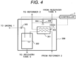
- Fig. 4 shows one example of the configuration of the separator.
- a separation unit 300 is configured by a condenser 301 and a drain tank 302.
- the temperature of a mixed gas including the reformed gas, ethanol vapor and water vapor and fed from the reformer 2 is approximately 300oC.
- the condenser 301 exchanges heat between the mixed gas fed from the reformer 2 and a predetermined cooling medium (coolant) and condenses water vapor included in the mixed gas.
- the mixed gas the water vapor of which is condensed in the condenser 301 and water are carried into the drain tank 302 and are separated into gas and liquid.
- the reformed gas and ethanol vapor separated into gas and liquid in the drain tank 302 are supplied to the engine 1.
- the condensed high-concentration water is extracted from a bottom of the drain tank 302 and is collected in the recovery tank 5.
- cooling water for the engine 1 and fluid such as air can also be used.
- the aqueous ethanol solution supplied to the reformer 2 from the reservoir tank 4 is used. That is, after the aqueous ethanol solution is supplied to the condenser 301 from the reservoir tank 4 and is heated by heat exchange with mixed gas in the condenser 301, the aqueous ethanol solution is supplied to the reformer 2.
- sensible heat and latent heat of the aqueous ethanol solution supplied to the reformer 2 can be collected in the condenser 301 and consequently, a rate of exhaust heat used for reforming reaction in the reformer 2 increases.
- the efficiency of the whole system can be enhanced.
- the temperature of mixed gas fed from the condenser 301 is controlled to be equal to or higher than 78oC which is the boiling point of ethanol and to be below 100oC which is the boiling point of water.
- Control over temperature is executed by the following method. As shown in Fig. 4 , a line 306 through which the aqueous ethanol solution is supplied from the reservoir tank 4 to the reformer 2 via the condenser 301 and a bypass line 307 through which the aqueous ethanol solution is directly supplied to the reformer 2 without passing the condenser 301 are provided, and regulating valves 303, 304 that can regulate a flow rate on respective lines are provided.
- a supplied amount of the aqueous ethanol solution supplied to a heat exchanger is adjusted by regulating an aperture of the regulating valves 303, 304 on the basis of the temperature detected by a temperature sensor 305 of mixed gas fed from the condenser 301 by the controller 7, and the temperature of the mixed gas after passing the condenser 301 is controlled.
- the temperature sensor 305 is installed on a line through which the reformed gas is supplied to the engine 1 from the drain tank 302.
- the temperature sensor may also be installed between the condenser 301 and in the drain tank 302 and in the drain tank 302.
- the temperature control method according to the configuration shown in Fig. 4 is one example, the temperature of mixed gas has only to be controlled, and another method may also be adopted.
- both aqueous ethanol solution from the reservoir tank 4 and recovery water supplied to the reformer 2 from the recovery tank 5 may also be used.
- sensible heat and latent heat of the recovery water supplied to the reformer 2 can be collected in the condenser 1 and a rate of exhaust heat utilized for reforming the aqueous ethanol solution in the reformer increases.
- the aqueous ethanol solution below 60 wt% is used for the aqueous ethanol solution let in the reservoir tank 4. This reason is that since the aqueous ethanol solution below 60 wt% as ethanol concentration does not correspond to hazardous materials of File Service Act, its handling is easy.
- a storage amount of the aqueous ethanol solution is not limited, large-capacity fuel can be more safely used and merit for a user is enhanced. Since the concentration of liquid in the recovery tank 5 is never equal to or higher than 60 wt% when ethanol concentration in the reservoir tank 4 is below 60 wt%, liquid used in this system is all out of a range of hazardous materials.
- controller 7 that electronically controls the ethanol engine system S will be described.
- the controller 7 is configured by CPU, ROM, RAM, various interfaces, electronic circuits and others and synthetically controls the ethanol engine system S according to a program stored inside.
- the controller 7 controls each supply device, the pump, the throttle and others respectively shown in Fig. 1 according to a procedure described later. The procedure which the controller 7 executes will be described in detail later together with the description of the operation of the ethanol engine system S.
- Fig. 5 shows an operation mode from starting to steady operation.
- a control signal that the aqueous ethanol solution is directly supplied to the engine is transmitted from the controller 7 to the second supply device 107 (a step S1).
- target torque and engine speed of the engine are measured (a step S2).
- the quantity of the aqueous ethanol solution supplied to the engine is determined according to the target torque and the engine speed and a control signal is transmitted from the controller 7 to the second hydrous ethanol supply device 107 (a step S3).
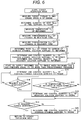
- Fig. 6 is a flowchart showing a procedure executed by the controller in the steady operation mode of the ethanol engine system S.
- the controller 7 instructs to measure target torque Tr and engine speed N of the engine 1 (a step S7) and determines a calorific value H total of fuel supplied to the engine 1 according to the target torque and the engine speed (a step S8).
- the controller 7 instructs of measure the temperature of the reformer 2 by the temperature sensor not shown arranged in the suitable location of the reaction cell of the reformer 2 (a step S9).
- the controller instructs concentration detectors 108, 106 to detect ethanol concentration D et1 in the reservoir tank 4 and ethanol concentration D et2 in the recovery tank 5 (steps S10, S11). At this time, when ethanol concentration D et1 in the reservoir tank 4 is already known, the detection is not required.
- the controller determines ratio X SC of water vapor to carbon in the aqueous ethanol solution supplied to the reformer 2 (a step S12) and determines the quantity Q et r of the aqueous ethanol solution supplied to the reformer 2 and the quantity Q wa r of the recovery solution supplied to the reformer (a step S13).
- the controller 7 issues a control instruction to the first supply device 103 and the first recovery solution supply device 102, and the aqueous ethanol solution and the recovery solution are supplied to the reformer 2. Calculation formulas are defined as follows.
- the quantity of ethanol supplied to the reformer shall be A and the quantity of water supplied to the reformer shall be B.
- A Q et r ⁇ D et 1 + Q wa r ⁇ D et 2
- B Q et r ⁇ 1 ⁇ D et 1 + Q wa r ⁇ 1 ⁇ D et 2
- S / C B / 0.5 ⁇ A
- a supplied amount of ethanol supplied to the reformer is calculated by the following expression on the basis of a calorific value of fuel required for the engine.
- A H total / H et / 1.24 ⁇ ⁇
- H et shall be a lower calorific value of ethanol.
- ⁇ is a correction coefficient and will be described later.
- the quantity Q et of the aqueous ethanol solution supplied to the reformer and the quantity Q wa r of the recovery solution supplied to the reformer are determined on the basis of the expressions (5) to (8) and the following expressions (9), (10).
- Q wa r A 1 ⁇ D et 1 1 ⁇ 0.5 X S / C / D et 1 / D et 2 1 ⁇ D et 1 / D et 1 ⁇ 1 ⁇ D et 2
- Q et r A ⁇ D et 2 ⁇ Q wa r / D et 1
- a calorific value of the reformed gas supplied to the engine is equal to or below H total according to the expression (8). Since the temperature, the pressure and a state of the catalyst of a reforming reaction location vary because exhaust heat of the engine is supplied to the reformer, conversion ratio in reforming from the aqueous ethanol solution to hydrogen and carbon monoxide varies. Therefore, it is difficult to meet torque required by a user by only heat supplied by the reformed gas. Accordingly, the calorific value of the reformed gas is set to be equal to or below H total using the expression (8) .
- the controller 7 issues a signal to the reformed gas supply device 101 so as to supply the reformed gas to the engine (a step 14). Afterward, the controller 7 determines the aqueous ethanol solution (Q et e ) supplied to the engine so as to meet required torque and transmits a signal to the second supply device 107 so as to adjust the quantity of the aqueous ethanol solution supplied to the engine (a step 15).
- a predetermined value the pressure of the reformed gas is measured by a pressure gage not shown
- the controller 7 determines whether the required torque is met or not (a step 16) and returns the process to the step 15 so as to adjust the aqueous ethanol solution (Q et e ) supplied to the engine when the required torque is not met.
- a step 16 determines whether the required torque is met or not.
- the controller 7 determines whether the temperature T re of the reformer 2 is in a range of predetermined temperature or not (a step S17).
- the predetermined temperature is for judging whether the reformer 2 is in a range of predetermined reforming temperature or not and is preset in a range of 250 to 500oC for example.
- each supplied quantity of the quantity of the aqueous ethanol solution (Q et r ) and the quantity of the recovery solution (Q wa r ) supplied to the reformer 2 is adjusted so as to set the temperature of the reformer 2 in the predetermined range.
- the reason is that when the temperature T re of the reformer is higher than the predetermined range, deterioration such as coking readily occurs in the reformer 2. Since reforming reaction in the expression (1) is endothermic reaction, the temperature T re of the reformer lowers when the quantity of the aqueous ethanol solution Q et r increases. To make the conversion ratio of reforming reaction equal to or higher than a predetermined value and to inhibit the deterioration of the reformer 2, the supply of the quantity of the aqueous ethanol solution Q et r and the quantity of the recovery solution Q wa r supplied to the reformer is adjusted so as to keep the temperature T re of the reformer in the predetermined range. Consequently, engine torque required by a user can be output, maximally enhancing a rate of the reformed gas supplied to the engine.
- the supply of supply of the quantity of the aqueous ethanol solution (Q et r ) and the quantity of the recovery solution (Q wa r ) supplied to the reformer 2 is adjusted by a correction factor ⁇ in the expression (8) concretely according to an instruction from the step S17 to the step S13.
- a correction factor ⁇ is increased and when the temperature T re of the reformer 2 is lower than the predetermined range, the correction factor ⁇ is decreased.
- the correction factor ⁇ is larger than 1, the abnormality in the temperature T re of the reformer is notified.
- the controller 7 determines the quantity Q wa e of the recovery solution supplied to the engine and the controller instructs the second recovery solution supply device 104 to supply the recovery solution to the engine (the step S12). This is determined by the rotating torque T r and the engine speed N of the engine.
- the controller 7 determines whether required torque is met or not (a step S19).
- the controller returns the process, when the torque is different from the required torque, the process proceeds to a step S20, and the quantity of the aqueous ethanol solution Q et e supplied to the engine is determined.
- the calorific value of the reformed gas depends upon the conversion ratio of the reformer, it is difficult to match the calorific value of the reformed gas with a calorific value of fuel required by the engine. Besides, cooling loss of the engine is reduced by supplying the recovery solution to the engine and consequently, engine torque increases. Thereby, fuel can be supplied to the engine in accordance with torque required by a user by adjusting the quantity of the aqueous ethanol solution Q et e supplied to the engine.
- the step 18 shown in Fig. 6 is omitted and control by the controller 7 is executed.
- the steps 11, 12 are omitted and a part of "DETERMINE AND CONTROL QUANTITY Q wa r OF RECOVERY SOLUTION SUPPLIED TO REFORMER" in the step 13 is omitted.
- the quantity Q et r of the aqueous ethanol solution supplied to the reformer is determined by the following expression (11).
- the quantity of ethanol A supplied to the reformer is calculated in the expression (8).
- Q et r A / D et 1
- An ethanol engine system equivalent to this embodiment generates motive power by supplying the reformed gas acquired by using ethanol for a carbon source and second fuel to an engine.
- the description of the same configuration as that in the first embodiment is omitted.
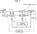
- Fig. 7 shows an example of another configuration of the ethanol engine system S.
- a fuel tank 8 separate from a reservoir tank 4 for reserving the aqueous ethanol solution is provided and second fuel is supplied from the second fuel tank 8 to the engine 1.
- the second fuel is hydrocarbon fuel such as gasoline, gas oil, natural gas and fuel oil.
- the second fuel is not limited to the hydrocarbon fuel, and the second fuel may also be fuel including no carbon content such as ammonia.
- the second fuel is supplied to the engine 1 via fuel supply equipment 109 in a state in which a supplied amount is adjusted. Since the reformed gas that uses the aqueous ethanol solution partially includes hydrogen, a combustible range is wider, compared with the second fuel and combustion velocity is fast.
- the recovery solution collected in a recovery tank 5 is directly supplied to a reformer 2 and the engine 1 via a first recovery solution supply device 102 and a second recovery solution supply device 104.
- a supplied amount of the recovery solution to the reformer 2 and the engine 1 is adjusted by the first recovery solution supply device 102 and the second recovery solution supply device 104.
- Fig. 8 is a partially enlarged view schematically showing the vicinity of a cylinder head in this embodiment.
- Fig. 8 is a schematic diagram showing the engine when gas oil and fuel oil which are respectively more ignitable, compared with the aqueous ethanol solution are used for the second fuel.
- the engine is a diesel engine.
- the reformed gas that passes a separator 5 as in the first embodiment is supplied to an intake pipe of the engine 1 by a reformed gas supply device 101, is premixed with air there, and is supplied to the inside of the engine.
- the second fuel is directly supplied into the engine 1 by the second fuel supply device 109 and is combusted by self-ignition caused by compression by a piston.
- Premixture of the reformed gas and air is ignited by the self-ignition combustion of the second fuel (a part is self-ignited) and expansion work by the piston can be extracted.
- gas oil and fuel oil are combusted in a normal diesel engine, soot and NOx are exhausted a lot because of diffusive combustion and an after-treatment device and others are required to be installed in an exhaust pipe.
- a rate of diffusive combustion by gas oil and fuel oil decreases and a rate of premixed combustion increases.
- the second recovery solution supply device 104 is connected to a combustion chamber of the engine for example and is provided with a structure that enables directly supplying water to the combustion chamber of the engine.
- the second recovery solution supply device enables cooling a part such as a piston in the combustion chamber.
- the piston is made of materials lower in thermal conductivity than an aluminum alloy. Therefore, supplied water has effect of inhibiting the temperature rise of the piston.
- Heat in the combustion chamber of the engine is thermally conducted to engine cooling water via a member such as a piston in the combustion chamber, however, the member of the engine combustion chamber can be cooled from the inside by supplying water into the engine and a heat transfer amount to engine cooling water can be reduced. Consequently, cooling loss can be reduced and thermal efficiency is enhanced.
- the ethanol engine system in this embodiment has a configuration that no aqueous ethanol solution is supplied to the engine 1, effect by the supply of the recovery solution into the combustion chamber of the engine 1 is great.
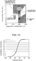
- Fig. 9 shows relation among an exhaust area of soot and NOx in the diffusive combustion of gas oil and fuel oil, equivalence ratio ( ⁇ ) and combustion temperature (Tc).
- ⁇ equivalence ratio
- Tc combustion temperature
- the exhaust of soot also decreases.
- the enhancement of thermal efficiency and the decrease of exhaust components such as soot and NOx can be simultaneously realized by supplying the reformed gas of the aqueous ethanol solution and the recovery solution to the diesel engine using the second fuel.
- biofuel is used for a diesel engine alone and in another case, biofuel is mixed with gas oil and their mixture is used.
- fuel called GTL is also used for a diesel engine in addition to biofuel. Since biodiesel fuel and GTL are different in ignitability, injection timing of fuel, injection quantity, an amount of EGR and supercharging pressure are normally controlled so as to enhance thermal efficiency and reduce exhaust components such as NOx and soot.
- the temperature of the inside of the engine can be lowered by latent heat of the evaporation of water by supplying water from the second recovery solution supply device 104.
- gas temperature in the engine can be controlled by controlling a supplied amount of the recovery solution to the engine and hereby, ignition timing of the second fuel can be controlled.
- combustion temperature can be controlled and exhaust components such as NOx and soot can also be reduced.
- combustion in which thermal efficiency is high and exhaust components such as soot and NOx are scarcely included can be realized by controlling the quantity of the recovery solution supplied from the second recovery solution supply device 104 when components of the second fuel vary. That is, a system applicable to a variety of fuel is formed.
- the second recovery solution supply device 104 may also be connected to the intake pipe of the engine without being directly installed in the combustion chamber. In that case, intake air can be cooled by latent heat of the evaporation of water and the above-mentioned similar effect is acquired.
- the operation of the ethanol engine system S in this embodiment shown in Fig. 7 is executed by partially changing the control flows shown in Fig. 5 and 6 .
- contents of the step S1 shown in Fig. 5 are changed to "SUPPLY SECOND FUEL TO ENGINE SO AS TO START ENGINE” and contents of the step S3 are changed to "DETERMINE AND CONTROL QUANTITY OF SECOND FUEL SUPPLIED TO ENGINE".
- "DETERMINE AND CONTROL QUANTITY OF AQUEOUS ETHANOL SOLUTION SUPPLIED TO ENGINE” in the steps S9 and S14 shown in Fig. 6 is changed to "DETERMINE AND CONTROL SUPPLIED AMOUNT OF SECOND FUEL SUPPLIED TO ENGINE".
- the ethanol engine system S shown in Fig. 7 has the configuration that the recovery solution can be supplied to both the engine 1 and the reformer 2.
- the ethanol engine system may also have a configuration that the recovery solution is supplied to only either of the reformer 2 or the combustion chamber of the engine 1 as in the first embodiment.
Landscapes
- Engineering & Computer Science (AREA)
- Chemical & Material Sciences (AREA)
- Combustion & Propulsion (AREA)
- Mechanical Engineering (AREA)
- General Engineering & Computer Science (AREA)
- Organic Chemistry (AREA)
- Chemical Kinetics & Catalysis (AREA)
- Inorganic Chemistry (AREA)
- Oil, Petroleum & Natural Gas (AREA)
- General Health & Medical Sciences (AREA)
- Health & Medical Sciences (AREA)
- Output Control And Ontrol Of Special Type Engine (AREA)
- Electrical Control Of Air Or Fuel Supplied To Internal-Combustion Engine (AREA)
- Hydrogen, Water And Hydrids (AREA)
Applications Claiming Priority (2)
| Application Number | Priority Date | Filing Date | Title |
|---|---|---|---|
| JP2014103914A JP6318000B2 (ja) | 2014-05-20 | 2014-05-20 | エタノールエンジンシステム |
| PCT/JP2015/064131 WO2015178327A1 (ja) | 2014-05-20 | 2015-05-18 | エタノールエンジンシステム |
Publications (3)
| Publication Number | Publication Date |
|---|---|
| EP3147492A4 EP3147492A4 (en) | 2017-03-29 |
| EP3147492A1 EP3147492A1 (en) | 2017-03-29 |
| EP3147492B1 true EP3147492B1 (en) | 2020-02-19 |
Family
ID=54553998
Family Applications (1)
| Application Number | Title | Priority Date | Filing Date |
|---|---|---|---|
| EP15796852.0A Active EP3147492B1 (en) | 2014-05-20 | 2015-05-18 | Ethanol engine system |
Country Status (4)
| Country | Link |
|---|---|
| US (1) | US10197019B2 (ja) |
| EP (1) | EP3147492B1 (ja) |
| JP (1) | JP6318000B2 (ja) |
| WO (1) | WO2015178327A1 (ja) |
Families Citing this family (11)
| Publication number | Priority date | Publication date | Assignee | Title |
|---|---|---|---|---|
| WO2017017754A1 (ja) * | 2015-07-27 | 2017-02-02 | 株式会社日立製作所 | パワートレインシステム |
| JP6639344B2 (ja) * | 2016-07-14 | 2020-02-05 | ヤンマー株式会社 | 内燃機関の制御装置および内燃機関の制御方法 |
| JP6639341B2 (ja) * | 2016-07-14 | 2020-02-05 | ヤンマー株式会社 | 内燃機関の制御装置および内燃機関の制御方法 |
| JP6639343B2 (ja) * | 2016-07-14 | 2020-02-05 | ヤンマー株式会社 | 内燃機関の制御装置および内燃機関の制御方法 |
| JP6633995B2 (ja) * | 2016-09-30 | 2020-01-22 | 株式会社日立製作所 | 燃料改質エンジンシステム及びその運転方法 |
| WO2018198436A1 (ja) * | 2017-04-24 | 2018-11-01 | 株式会社マリネックス | 噴射装置およびこれを備えた動力装置 |
| JP2021175875A (ja) * | 2018-05-31 | 2021-11-04 | 株式会社日立製作所 | 燃料分離改質エンジンシステム |
| JP2022531863A (ja) | 2019-05-15 | 2022-07-12 | クリアフレーム エンジンズ,インコーポレイテッド | ディーゼルエンジンアーキテクチャにおける高オクタン価燃料の冷間始動 |
| JP2023516273A (ja) | 2020-02-26 | 2023-04-19 | クリアフレーム エンジンズ,インコーポレイテッド | 燃料に依存しない圧縮着火エンジン |
| JP2023533965A (ja) | 2020-07-09 | 2023-08-07 | クリアフレーム エンジンズ,インコーポレイテッド | 高温混合制御エンジンにおける気筒休止のシステム及び方法 |
| US12078115B1 (en) * | 2023-06-20 | 2024-09-03 | Caterpillar Inc. | Systems and methods for pilot fuel synthesis using engine waste heat |
Family Cites Families (8)
| Publication number | Priority date | Publication date | Assignee | Title |
|---|---|---|---|---|
| JP2007056813A (ja) * | 2005-08-25 | 2007-03-08 | Nissan Motor Co Ltd | 燃料供給装置 |
| JP4449956B2 (ja) * | 2006-08-04 | 2010-04-14 | トヨタ自動車株式会社 | 内燃機関 |
| JP4840307B2 (ja) * | 2007-09-20 | 2011-12-21 | 株式会社豊田中央研究所 | エンジンシステム |
| JP4951592B2 (ja) * | 2008-07-07 | 2012-06-13 | 本田技研工業株式会社 | 内燃機関の制御装置 |
| JP2010106774A (ja) | 2008-10-30 | 2010-05-13 | Toyota Central R&D Labs Inc | 改質ガスエンジンシステム |
| US8967089B2 (en) * | 2009-06-29 | 2015-03-03 | Monsanto Technology Llc | Reformed ethanol engines |
| JP5916109B2 (ja) | 2012-03-29 | 2016-05-11 | 株式会社日立製作所 | エタノールエンジンシステム |
| CN104321520B (zh) | 2012-03-30 | 2017-05-24 | 孟山都技术公司 | 用于内燃机的醇重整系统 |
-
2014
- 2014-05-20 JP JP2014103914A patent/JP6318000B2/ja active Active
-
2015
- 2015-05-18 EP EP15796852.0A patent/EP3147492B1/en active Active
- 2015-05-18 WO PCT/JP2015/064131 patent/WO2015178327A1/ja active Application Filing
- 2015-05-18 US US15/311,991 patent/US10197019B2/en active Active
Non-Patent Citations (1)
| Title |
|---|
| None * |
Also Published As
| Publication number | Publication date |
|---|---|
| EP3147492A4 (en) | 2017-03-29 |
| JP2015218676A (ja) | 2015-12-07 |
| WO2015178327A1 (ja) | 2015-11-26 |
| EP3147492A1 (en) | 2017-03-29 |
| US20170089306A1 (en) | 2017-03-30 |
| JP6318000B2 (ja) | 2018-04-25 |
| US10197019B2 (en) | 2019-02-05 |
Similar Documents
| Publication | Publication Date | Title |
|---|---|---|
| EP3147492B1 (en) | Ethanol engine system | |
| JP4449956B2 (ja) | 内燃機関 | |
| EP2216537B1 (en) | Internal combustion engine | |
| JP2010025031A (ja) | 燃料改質装置 | |
| JP4840307B2 (ja) | エンジンシステム | |
| Li et al. | A novel strategy for hydrous-ethanol utilization: Demonstration of a spark-ignition engine fueled with hydrogen-rich fuel from an onboard ethanol/steam reformer | |
| EP1972776A2 (en) | Octane number-increasing catalyst, fuel reformer of internal combustion engine, and the internal combustion engine | |
| WO2016113811A1 (ja) | 燃料改質装置 | |
| JP5916109B2 (ja) | エタノールエンジンシステム | |
| Hwang et al. | Hydrous ethanol steam reforming and thermochemical recuperation to improve dual-fuel diesel engine emissions and efficiency | |
| JP2008215322A (ja) | エンジンシステム | |
| US20100112392A1 (en) | Method for regenerating a reformer | |
| JP6633995B2 (ja) | 燃料改質エンジンシステム及びその運転方法 | |
| JP4788615B2 (ja) | 内燃機関の燃料性状判定装置 | |
| JP5696215B2 (ja) | エンジンシステム | |
| JP2001234818A (ja) | 燃料改質装置付き内燃機関 | |
| WO2019230226A1 (ja) | 燃料分離改質エンジンシステム | |
| EP3686420B1 (en) | Internal combustion engine | |
| JP2008240707A (ja) | 燃料改質器付き内燃機関 | |
| JP2008286097A (ja) | エタノール改質システム | |
| US12078115B1 (en) | Systems and methods for pilot fuel synthesis using engine waste heat | |
| JP2005085478A (ja) | 電源システムおよびその運転方法 | |
| US20200248617A1 (en) | Cogeneration System | |
| EP2212958B1 (en) | Auxiliary power unit | |
| CN2525377Y (zh) | 氢氧燃料产生机的火焰温度调节器 |
Legal Events
| Date | Code | Title | Description |
|---|---|---|---|
| STAA | Information on the status of an ep patent application or granted ep patent |
Free format text: STATUS: THE INTERNATIONAL PUBLICATION HAS BEEN MADE |
|
| PUAI | Public reference made under article 153(3) epc to a published international application that has entered the european phase |
Free format text: ORIGINAL CODE: 0009012 |
|
| STAA | Information on the status of an ep patent application or granted ep patent |
Free format text: STATUS: REQUEST FOR EXAMINATION WAS MADE |
|
| 17P | Request for examination filed |
Effective date: 20161220 |
|
| A4 | Supplementary search report drawn up and despatched |
Effective date: 20170209 |
|
| AK | Designated contracting states |
Kind code of ref document: A1 Designated state(s): AL AT BE BG CH CY CZ DE DK EE ES FI FR GB GR HR HU IE IS IT LI LT LU LV MC MK MT NL NO PL PT RO RS SE SI SK SM TR |
|
| AX | Request for extension of the european patent |
Extension state: BA ME |
|
| DAV | Request for validation of the european patent (deleted) | ||
| DAX | Request for extension of the european patent (deleted) | ||
| STAA | Information on the status of an ep patent application or granted ep patent |
Free format text: STATUS: EXAMINATION IS IN PROGRESS |
|
| 17Q | First examination report despatched |
Effective date: 20190212 |
|
| GRAP | Despatch of communication of intention to grant a patent |
Free format text: ORIGINAL CODE: EPIDOSNIGR1 |
|
| STAA | Information on the status of an ep patent application or granted ep patent |
Free format text: STATUS: GRANT OF PATENT IS INTENDED |
|
| INTG | Intention to grant announced |
Effective date: 20190902 |
|
| GRAS | Grant fee paid |
Free format text: ORIGINAL CODE: EPIDOSNIGR3 |
|
| GRAA | (expected) grant |
Free format text: ORIGINAL CODE: 0009210 |
|
| STAA | Information on the status of an ep patent application or granted ep patent |
Free format text: STATUS: THE PATENT HAS BEEN GRANTED |
|
| AK | Designated contracting states |
Kind code of ref document: B1 Designated state(s): AL AT BE BG CH CY CZ DE DK EE ES FI FR GB GR HR HU IE IS IT LI LT LU LV MC MK MT NL NO PL PT RO RS SE SI SK SM TR |
|
| REG | Reference to a national code |
Ref country code: CH Ref legal event code: EP |
|
| REG | Reference to a national code |
Ref country code: SE Ref legal event code: TRGR |
|
| REG | Reference to a national code |
Ref country code: DE Ref legal event code: R096 Ref document number: 602015047389 Country of ref document: DE |
|
| REG | Reference to a national code |
Ref country code: AT Ref legal event code: REF Ref document number: 1235248 Country of ref document: AT Kind code of ref document: T Effective date: 20200315 |
|
| REG | Reference to a national code |
Ref country code: IE Ref legal event code: FG4D |
|
| REG | Reference to a national code |
Ref country code: NL Ref legal event code: MP Effective date: 20200219 |
|
| PG25 | Lapsed in a contracting state [announced via postgrant information from national office to epo] |
Ref country code: RS Free format text: LAPSE BECAUSE OF FAILURE TO SUBMIT A TRANSLATION OF THE DESCRIPTION OR TO PAY THE FEE WITHIN THE PRESCRIBED TIME-LIMIT Effective date: 20200219 Ref country code: NO Free format text: LAPSE BECAUSE OF FAILURE TO SUBMIT A TRANSLATION OF THE DESCRIPTION OR TO PAY THE FEE WITHIN THE PRESCRIBED TIME-LIMIT Effective date: 20200519 Ref country code: FI Free format text: LAPSE BECAUSE OF FAILURE TO SUBMIT A TRANSLATION OF THE DESCRIPTION OR TO PAY THE FEE WITHIN THE PRESCRIBED TIME-LIMIT Effective date: 20200219 |
|
| REG | Reference to a national code |
Ref country code: LT Ref legal event code: MG4D |
|
| PG25 | Lapsed in a contracting state [announced via postgrant information from national office to epo] |
Ref country code: IS Free format text: LAPSE BECAUSE OF FAILURE TO SUBMIT A TRANSLATION OF THE DESCRIPTION OR TO PAY THE FEE WITHIN THE PRESCRIBED TIME-LIMIT Effective date: 20200619 Ref country code: BG Free format text: LAPSE BECAUSE OF FAILURE TO SUBMIT A TRANSLATION OF THE DESCRIPTION OR TO PAY THE FEE WITHIN THE PRESCRIBED TIME-LIMIT Effective date: 20200519 Ref country code: GR Free format text: LAPSE BECAUSE OF FAILURE TO SUBMIT A TRANSLATION OF THE DESCRIPTION OR TO PAY THE FEE WITHIN THE PRESCRIBED TIME-LIMIT Effective date: 20200520 Ref country code: HR Free format text: LAPSE BECAUSE OF FAILURE TO SUBMIT A TRANSLATION OF THE DESCRIPTION OR TO PAY THE FEE WITHIN THE PRESCRIBED TIME-LIMIT Effective date: 20200219 Ref country code: LV Free format text: LAPSE BECAUSE OF FAILURE TO SUBMIT A TRANSLATION OF THE DESCRIPTION OR TO PAY THE FEE WITHIN THE PRESCRIBED TIME-LIMIT Effective date: 20200219 |
|
| PG25 | Lapsed in a contracting state [announced via postgrant information from national office to epo] |
Ref country code: NL Free format text: LAPSE BECAUSE OF FAILURE TO SUBMIT A TRANSLATION OF THE DESCRIPTION OR TO PAY THE FEE WITHIN THE PRESCRIBED TIME-LIMIT Effective date: 20200219 |
|
| PG25 | Lapsed in a contracting state [announced via postgrant information from national office to epo] |
Ref country code: DK Free format text: LAPSE BECAUSE OF FAILURE TO SUBMIT A TRANSLATION OF THE DESCRIPTION OR TO PAY THE FEE WITHIN THE PRESCRIBED TIME-LIMIT Effective date: 20200219 Ref country code: SM Free format text: LAPSE BECAUSE OF FAILURE TO SUBMIT A TRANSLATION OF THE DESCRIPTION OR TO PAY THE FEE WITHIN THE PRESCRIBED TIME-LIMIT Effective date: 20200219 Ref country code: EE Free format text: LAPSE BECAUSE OF FAILURE TO SUBMIT A TRANSLATION OF THE DESCRIPTION OR TO PAY THE FEE WITHIN THE PRESCRIBED TIME-LIMIT Effective date: 20200219 Ref country code: SK Free format text: LAPSE BECAUSE OF FAILURE TO SUBMIT A TRANSLATION OF THE DESCRIPTION OR TO PAY THE FEE WITHIN THE PRESCRIBED TIME-LIMIT Effective date: 20200219 Ref country code: PT Free format text: LAPSE BECAUSE OF FAILURE TO SUBMIT A TRANSLATION OF THE DESCRIPTION OR TO PAY THE FEE WITHIN THE PRESCRIBED TIME-LIMIT Effective date: 20200712 Ref country code: CZ Free format text: LAPSE BECAUSE OF FAILURE TO SUBMIT A TRANSLATION OF THE DESCRIPTION OR TO PAY THE FEE WITHIN THE PRESCRIBED TIME-LIMIT Effective date: 20200219 Ref country code: ES Free format text: LAPSE BECAUSE OF FAILURE TO SUBMIT A TRANSLATION OF THE DESCRIPTION OR TO PAY THE FEE WITHIN THE PRESCRIBED TIME-LIMIT Effective date: 20200219 Ref country code: LT Free format text: LAPSE BECAUSE OF FAILURE TO SUBMIT A TRANSLATION OF THE DESCRIPTION OR TO PAY THE FEE WITHIN THE PRESCRIBED TIME-LIMIT Effective date: 20200219 Ref country code: RO Free format text: LAPSE BECAUSE OF FAILURE TO SUBMIT A TRANSLATION OF THE DESCRIPTION OR TO PAY THE FEE WITHIN THE PRESCRIBED TIME-LIMIT Effective date: 20200219 |
|
| REG | Reference to a national code |
Ref country code: AT Ref legal event code: MK05 Ref document number: 1235248 Country of ref document: AT Kind code of ref document: T Effective date: 20200219 |
|
| REG | Reference to a national code |
Ref country code: DE Ref legal event code: R097 Ref document number: 602015047389 Country of ref document: DE |
|
| PLBE | No opposition filed within time limit |
Free format text: ORIGINAL CODE: 0009261 |
|
| STAA | Information on the status of an ep patent application or granted ep patent |
Free format text: STATUS: NO OPPOSITION FILED WITHIN TIME LIMIT |
|
| 26N | No opposition filed |
Effective date: 20201120 |
|
| PG25 | Lapsed in a contracting state [announced via postgrant information from national office to epo] |
Ref country code: IT Free format text: LAPSE BECAUSE OF FAILURE TO SUBMIT A TRANSLATION OF THE DESCRIPTION OR TO PAY THE FEE WITHIN THE PRESCRIBED TIME-LIMIT Effective date: 20200219 Ref country code: MC Free format text: LAPSE BECAUSE OF FAILURE TO SUBMIT A TRANSLATION OF THE DESCRIPTION OR TO PAY THE FEE WITHIN THE PRESCRIBED TIME-LIMIT Effective date: 20200219 Ref country code: AT Free format text: LAPSE BECAUSE OF FAILURE TO SUBMIT A TRANSLATION OF THE DESCRIPTION OR TO PAY THE FEE WITHIN THE PRESCRIBED TIME-LIMIT Effective date: 20200219 Ref country code: LI Free format text: LAPSE BECAUSE OF NON-PAYMENT OF DUE FEES Effective date: 20200531 Ref country code: CH Free format text: LAPSE BECAUSE OF NON-PAYMENT OF DUE FEES Effective date: 20200531 |
|
| PG25 | Lapsed in a contracting state [announced via postgrant information from national office to epo] |
Ref country code: SI Free format text: LAPSE BECAUSE OF FAILURE TO SUBMIT A TRANSLATION OF THE DESCRIPTION OR TO PAY THE FEE WITHIN THE PRESCRIBED TIME-LIMIT Effective date: 20200219 Ref country code: PL Free format text: LAPSE BECAUSE OF FAILURE TO SUBMIT A TRANSLATION OF THE DESCRIPTION OR TO PAY THE FEE WITHIN THE PRESCRIBED TIME-LIMIT Effective date: 20200219 |
|
| REG | Reference to a national code |
Ref country code: BE Ref legal event code: MM Effective date: 20200531 |
|
| GBPC | Gb: european patent ceased through non-payment of renewal fee |
Effective date: 20200519 |
|
| PG25 | Lapsed in a contracting state [announced via postgrant information from national office to epo] |
Ref country code: LU Free format text: LAPSE BECAUSE OF NON-PAYMENT OF DUE FEES Effective date: 20200518 |
|
| PG25 | Lapsed in a contracting state [announced via postgrant information from national office to epo] |
Ref country code: IE Free format text: LAPSE BECAUSE OF NON-PAYMENT OF DUE FEES Effective date: 20200518 Ref country code: GB Free format text: LAPSE BECAUSE OF NON-PAYMENT OF DUE FEES Effective date: 20200519 |
|
| PG25 | Lapsed in a contracting state [announced via postgrant information from national office to epo] |
Ref country code: BE Free format text: LAPSE BECAUSE OF NON-PAYMENT OF DUE FEES Effective date: 20200531 |
|
| PG25 | Lapsed in a contracting state [announced via postgrant information from national office to epo] |
Ref country code: TR Free format text: LAPSE BECAUSE OF FAILURE TO SUBMIT A TRANSLATION OF THE DESCRIPTION OR TO PAY THE FEE WITHIN THE PRESCRIBED TIME-LIMIT Effective date: 20200219 Ref country code: MT Free format text: LAPSE BECAUSE OF FAILURE TO SUBMIT A TRANSLATION OF THE DESCRIPTION OR TO PAY THE FEE WITHIN THE PRESCRIBED TIME-LIMIT Effective date: 20200219 Ref country code: CY Free format text: LAPSE BECAUSE OF FAILURE TO SUBMIT A TRANSLATION OF THE DESCRIPTION OR TO PAY THE FEE WITHIN THE PRESCRIBED TIME-LIMIT Effective date: 20200219 |
|
| PG25 | Lapsed in a contracting state [announced via postgrant information from national office to epo] |
Ref country code: MK Free format text: LAPSE BECAUSE OF FAILURE TO SUBMIT A TRANSLATION OF THE DESCRIPTION OR TO PAY THE FEE WITHIN THE PRESCRIBED TIME-LIMIT Effective date: 20200219 Ref country code: AL Free format text: LAPSE BECAUSE OF FAILURE TO SUBMIT A TRANSLATION OF THE DESCRIPTION OR TO PAY THE FEE WITHIN THE PRESCRIBED TIME-LIMIT Effective date: 20200219 |
|
| REG | Reference to a national code |
Ref country code: FR Ref legal event code: PLFP Year of fee payment: 9 |
|
| PGFP | Annual fee paid to national office [announced via postgrant information from national office to epo] |
Ref country code: DE Payment date: 20230331 Year of fee payment: 9 |
|
| PGFP | Annual fee paid to national office [announced via postgrant information from national office to epo] |
Ref country code: FR Payment date: 20240328 Year of fee payment: 10 |
|
| PGFP | Annual fee paid to national office [announced via postgrant information from national office to epo] |
Ref country code: SE Payment date: 20240328 Year of fee payment: 10 |