EP3147133A1 - Metal mask and screen printing apparatus - Google Patents
Metal mask and screen printing apparatus Download PDFInfo
- Publication number
- EP3147133A1 EP3147133A1 EP14892307.1A EP14892307A EP3147133A1 EP 3147133 A1 EP3147133 A1 EP 3147133A1 EP 14892307 A EP14892307 A EP 14892307A EP 3147133 A1 EP3147133 A1 EP 3147133A1
- Authority
- EP
- European Patent Office
- Prior art keywords
- metal mask
- openings
- opening
- gasket
- separator
- Prior art date
- Legal status (The legal status is an assumption and is not a legal conclusion. Google has not performed a legal analysis and makes no representation as to the accuracy of the status listed.)
- Granted
Links
Images


Classifications
-
- B—PERFORMING OPERATIONS; TRANSPORTING
- B41—PRINTING; LINING MACHINES; TYPEWRITERS; STAMPS
- B41F—PRINTING MACHINES OR PRESSES
- B41F15/00—Screen printers
- B41F15/14—Details
- B41F15/34—Screens, Frames; Holders therefor
-
- B—PERFORMING OPERATIONS; TRANSPORTING
- B41—PRINTING; LINING MACHINES; TYPEWRITERS; STAMPS
- B41C—PROCESSES FOR THE MANUFACTURE OR REPRODUCTION OF PRINTING SURFACES
- B41C1/00—Forme preparation
- B41C1/14—Forme preparation for stencil-printing or silk-screen printing
-
- B—PERFORMING OPERATIONS; TRANSPORTING
- B41—PRINTING; LINING MACHINES; TYPEWRITERS; STAMPS
- B41F—PRINTING MACHINES OR PRESSES
- B41F15/00—Screen printers
- B41F15/08—Machines
- B41F15/0881—Machines for printing on polyhedral articles
-
- B—PERFORMING OPERATIONS; TRANSPORTING
- B41—PRINTING; LINING MACHINES; TYPEWRITERS; STAMPS
- B41F—PRINTING MACHINES OR PRESSES
- B41F15/00—Screen printers
- B41F15/14—Details
- B41F15/34—Screens, Frames; Holders therefor
- B41F15/36—Screens, Frames; Holders therefor flat
-
- B—PERFORMING OPERATIONS; TRANSPORTING
- B41—PRINTING; LINING MACHINES; TYPEWRITERS; STAMPS
- B41F—PRINTING MACHINES OR PRESSES
- B41F15/00—Screen printers
- B41F15/14—Details
- B41F15/44—Squeegees or doctors
-
- B—PERFORMING OPERATIONS; TRANSPORTING
- B41—PRINTING; LINING MACHINES; TYPEWRITERS; STAMPS
- B41N—PRINTING PLATES OR FOILS; MATERIALS FOR SURFACES USED IN PRINTING MACHINES FOR PRINTING, INKING, DAMPING, OR THE LIKE; PREPARING SUCH SURFACES FOR USE AND CONSERVING THEM
- B41N1/00—Printing plates or foils; Materials therefor
- B41N1/24—Stencils; Stencil materials; Carriers therefor
-
- H—ELECTRICITY
- H01—ELECTRIC ELEMENTS
- H01M—PROCESSES OR MEANS, e.g. BATTERIES, FOR THE DIRECT CONVERSION OF CHEMICAL ENERGY INTO ELECTRICAL ENERGY
- H01M8/00—Fuel cells; Manufacture thereof
- H01M8/02—Details
- H01M8/0271—Sealing or supporting means around electrodes, matrices or membranes
- H01M8/028—Sealing means characterised by their material
- H01M8/0284—Organic resins; Organic polymers
-
- H—ELECTRICITY
- H01—ELECTRIC ELEMENTS
- H01M—PROCESSES OR MEANS, e.g. BATTERIES, FOR THE DIRECT CONVERSION OF CHEMICAL ENERGY INTO ELECTRICAL ENERGY
- H01M8/00—Fuel cells; Manufacture thereof
- H01M8/02—Details
- H01M8/0271—Sealing or supporting means around electrodes, matrices or membranes
- H01M8/0286—Processes for forming seals
-
- H—ELECTRICITY
- H05—ELECTRIC TECHNIQUES NOT OTHERWISE PROVIDED FOR
- H05K—PRINTED CIRCUITS; CASINGS OR CONSTRUCTIONAL DETAILS OF ELECTRIC APPARATUS; MANUFACTURE OF ASSEMBLAGES OF ELECTRICAL COMPONENTS
- H05K3/00—Apparatus or processes for manufacturing printed circuits
- H05K3/10—Apparatus or processes for manufacturing printed circuits in which conductive material is applied to the insulating support in such a manner as to form the desired conductive pattern
- H05K3/12—Apparatus or processes for manufacturing printed circuits in which conductive material is applied to the insulating support in such a manner as to form the desired conductive pattern using thick film techniques, e.g. printing techniques to apply the conductive material or similar techniques for applying conductive paste or ink patterns
-
- H—ELECTRICITY
- H05—ELECTRIC TECHNIQUES NOT OTHERWISE PROVIDED FOR
- H05K—PRINTED CIRCUITS; CASINGS OR CONSTRUCTIONAL DETAILS OF ELECTRIC APPARATUS; MANUFACTURE OF ASSEMBLAGES OF ELECTRICAL COMPONENTS
- H05K3/00—Apparatus or processes for manufacturing printed circuits
- H05K3/10—Apparatus or processes for manufacturing printed circuits in which conductive material is applied to the insulating support in such a manner as to form the desired conductive pattern
- H05K3/12—Apparatus or processes for manufacturing printed circuits in which conductive material is applied to the insulating support in such a manner as to form the desired conductive pattern using thick film techniques, e.g. printing techniques to apply the conductive material or similar techniques for applying conductive paste or ink patterns
- H05K3/1216—Apparatus or processes for manufacturing printed circuits in which conductive material is applied to the insulating support in such a manner as to form the desired conductive pattern using thick film techniques, e.g. printing techniques to apply the conductive material or similar techniques for applying conductive paste or ink patterns by screen printing or stencil printing
- H05K3/1233—Methods or means for supplying the conductive material and for forcing it through the screen or stencil
-
- H—ELECTRICITY
- H01—ELECTRIC ELEMENTS
- H01M—PROCESSES OR MEANS, e.g. BATTERIES, FOR THE DIRECT CONVERSION OF CHEMICAL ENERGY INTO ELECTRICAL ENERGY
- H01M8/00—Fuel cells; Manufacture thereof
- H01M8/10—Fuel cells with solid electrolytes
- H01M2008/1095—Fuel cells with polymeric electrolytes
-
- H—ELECTRICITY
- H05—ELECTRIC TECHNIQUES NOT OTHERWISE PROVIDED FOR
- H05K—PRINTED CIRCUITS; CASINGS OR CONSTRUCTIONAL DETAILS OF ELECTRIC APPARATUS; MANUFACTURE OF ASSEMBLAGES OF ELECTRICAL COMPONENTS
- H05K2203/00—Indexing scheme relating to apparatus or processes for manufacturing printed circuits covered by H05K3/00
- H05K2203/01—Tools for processing; Objects used during processing
- H05K2203/0104—Tools for processing; Objects used during processing for patterning or coating
- H05K2203/0139—Blade or squeegee, e.g. for screen printing or filling of holes
-
- Y—GENERAL TAGGING OF NEW TECHNOLOGICAL DEVELOPMENTS; GENERAL TAGGING OF CROSS-SECTIONAL TECHNOLOGIES SPANNING OVER SEVERAL SECTIONS OF THE IPC; TECHNICAL SUBJECTS COVERED BY FORMER USPC CROSS-REFERENCE ART COLLECTIONS [XRACs] AND DIGESTS
- Y02—TECHNOLOGIES OR APPLICATIONS FOR MITIGATION OR ADAPTATION AGAINST CLIMATE CHANGE
- Y02E—REDUCTION OF GREENHOUSE GAS [GHG] EMISSIONS, RELATED TO ENERGY GENERATION, TRANSMISSION OR DISTRIBUTION
- Y02E60/00—Enabling technologies; Technologies with a potential or indirect contribution to GHG emissions mitigation
- Y02E60/30—Hydrogen technology
- Y02E60/50—Fuel cells
Definitions
- the present invention relates to a metal mask and a screen printing apparatus.
- PEFC Polymer electrolyte fuel cells
- a polymer electrolyte fuel cell comprises an electrolyte membrane, a catalyst layer formed on both sides of the electrolyte membrane, and a membrane electrode assembly (Membrane Electrode Assembly, hereinafter referred to as MEA) that has a gas diffusion layer (GDL), etc.
- MEA Membrane Electrode Assembly
- GDL gas diffusion layer
- a fuel cell is configured by layering a plurality of MEAs with interposed separators.
- the screen printing method is used in the manufacture of fuel cells and is a known technique in which an adhesive is applied in a rectangular shape, forming a gasket on the surface of the separator.
- a separator as the object to be printed is disposed separated on the lower surface of a metal mask provided with openings, a gasket as a printing material is placed on the upper surface of the metal mask, and a squeegee is pressed and slid over the separator. Accordingly, the gasket is passed through the openings provided in the metal mask, and the gasket is applied onto the surface of the separator by transfer molding.
- the separator on the surface of which the gasket is applied, is pressurized and laminated with another separator so that the gaskets face each other.
- the separator is pressurized and laminated with another separator so that the gaskets face each other.
- a surface on one side of a bridge that is disposed between a pair of openings is aligned with a surface on the side over which the squeegee is slid, and the surface of the other side of the bridge is recessed from the back surface on the side that is opposite the side on which the squeegee is slid.
- the bridge is provided so at to connect the pair of openings.
- the gasket is filled in the recess provided on the other side surface of the bridge along with the openings by the sliding of the squeegee; therefore, it is possible to apply the gasket having a continuous closed pattern on the surface of the separator.
- Patent Document 1 Japanese Laid Open Patent Application No. 2007-331195
- the present invention provides a metal mask and a screen printing apparatus that are capable of preventing problems caused by the small application amount of printing material that is applied to the object to be printed.
- the metal mask according to the present invention that achieves the object described above is used to apply printing materials to an object to be printed by the sliding of a squeegee.
- the metal mask is a metal mask for screen printing on which are formed a plurality of openings that pass through from a first surface on a side to which the squeegee is provided to a second surface on a side to which the object to be printed is provided.
- the metal mask comprises a bridge portion that is disposed between one of the openings and the other of the openings, and that is recessed from the second surface.
- the metal mask comprises a filling portion that is provided on the second surface side of the bridge portion, and in which is filled the printing material by the sliding of the squeegee.
- the filling portion communicates with the respective ends of the one opening and the other opening and, when viewed from the second surface, has a width in a second direction that intersects a first direction extending from the one opening to the other opening that is larger than the width of the openings in the second direction.
- the screen printing apparatus according to the present invention that achieves the object above is a screen printing apparatus that has the metal mask described above.
- the metal mask and the screen printing apparatus configured as described above, of the printing material that is applied to the surface of the object to be printed, in the area where the thickness in the height direction is thin corresponding to the area where the bridge portion is provided, a pattern is formed that is wider than in the other areas in the second direction. Therefore, it is possible to prevent problems caused by the small application amount of printing material that is applied to the object to be printed. Specifically, when such objects to be printed are laminated one on top of another, since the printing material is formed wide in the second direction in the area where the height direction thickness is thin, it is possible to more reliably seal the internal space of the printing material. Therefore, it is possible to provide a metal mask and a screen printing apparatus that are well able to prevent the generation of gaps between laminated printing materials and the leaking of gas to the outside.
- Figure 1 is a cross-sectional view illustrating the cell structure of a fuel cell.
- a single cell 10 is applied to a polymer electrolyte fuel cell (PEFC), and the like, which uses hydrogen as fuel, and comprises an MEA 20, a pair of separators 31, 32 and a pair of gaskets 41, 42, as illustrated in Figure 1 .
- PEFC polymer electrolyte fuel cell
- the MEA 20 comprises a polymer electrolyte membrane 21, a pair of catalyst layer 22, 23 and a pair of gas diffusion layers (GDL: Gas Diffusion Layer) 24, 25.
- GDL Gas Diffusion Layer
- the catalyst layer 22 comprises a catalyst component, a conductive catalyst carrier that supports the catalyst component and polymer electrolytes; and is an anode catalyst layer in which the oxidative reaction of hydrogen progresses, and is disposed on one side of the electrolyte membrane 21.
- the catalyst layer 23 comprises a catalyst component, a conductive catalyst carrier that supports the catalyst component and polymer electrolytes; and is a cathode catalyst layer in which the reductive reaction of oxygen progresses, and is disposed on the other side of the electrolyte membrane 21.
- the electrolyte membrane 21 has a function of selectively transmitting protons generated in the catalyst layer 22 to the catalyst layer 23, and a function of acting as a barrier to prevent fuel gas that is supplied to the anode side and the oxidant gas that is supplied to the cathode side from mixing.
- the gas diffusion layer 24 is an anode gas diffusion layer for dispersing the fuel gas that is supplied to the anode side, and is positioned between the separator 31 and the catalyst layer 22.
- the gas diffusion layer 25 is a cathode gas diffusion layer for dispersing the oxidant gas that is supplied to the cathode side, and is positioned between the separator 32 and the catalyst layer 23.
- the separators 31, 32 have a function of electrically connecting the single cells 10 in series, and a function of acting as a barrier to mutually block the fuel gas, the oxidant gas, and the refrigerant from each other.
- the separators 31, 32 have substantially the same shape as the MEA 20, and are formed by, for example, press working a stainless steel plate. Stainless steel plates are preferable in that complex machining can be easily applied thereto and that the conductivity is good, and it is also possible to apply corrosion resistant coating thereto, if necessary.
- the separator 31 is an anode separator that is disposed on the anode side of the MEA 20, and comprises a groove portion 31a that faces the catalyst layer 22 and that configures a gas flow channel that is positioned between the MEA 20 and the separator 31.
- the groove portion 31a is used to supply fuel gas to the catalyst layer 22.
- the separator 32 is a cathode separator that is disposed on the cathode side of the MEA 20, and comprises a groove portion 32a that faces the catalyst layer 23 and that configures a gas flow channel that is positioned between the MEA 20 and the separator 32.
- the groove portion 32a is used to supply oxidant gas to the catalyst layer 23.
- the gaskets 41, 42 are frame-shaped and are disposed on both sides of the outer perimeter part of the electrolyte membrane 21.
- the gaskets 41, 42 are applied by a screen printing apparatus 100, to be described below.
- the gasket 41 is applied to surround the catalyst layer 22 (and the gas diffusion layer 24), and has a function of preventing the fuel gas that is supplied to the catalyst layer 22 from leaking to the outside.
- the gasket 42 is applied to surround the catalyst layer 23 (and the gas diffusion layer 25), and has a function of preventing the oxidant gas that is supplied to the catalyst layer 23 from leaking to the outside.
- fluorine-based electrolyte membranes composed of perfluorocarbon sulfonic acid polymers, hydrocarbon-based electrolyte membranes having a sulfonic acid group, and porous membranes impregnated with electrolyte components, such as phosphoric acid and ionic liquid.
- perfluorocarbon sulfonic acid polymers include Nafion (registered trademark, DuPont Co., Ltd.), Aciplex (registered trademark, Asahi Kasei Corporation), and Flemion (registered trademark, Asahi Glass Co., Ltd.) can be used.
- the porous membrane is formed from, for example, polytetratluoroethylene (PTFE) or polyvinylidene-fluoride (PVDF).
- the thickness of the electrolyte membrane 21 is not particularly limited, but is preferably 5-300 ⁇ m, and more preferably 10-200 ⁇ m, from the standpoint of strength, durability, and output characteristics.
- the catalyst component that is used for the catalyst layer (cathode catalyst layer) 23 is not particularly limited and can be any component that has a catalytic effect in the reductive reaction of oxygen.
- the catalyst component that is used for the catalyst layer (anode catalyst layer) 22 is not particularly limited and can be any component that has a catalytic effect in the oxidative reaction of hydrogen.
- Specific catalyst components are selected from such metals as platinum, ruthenium, iridium, rhodium, palladium, osmium, tungsten, lead, iron, chromium, cobalt, nickel, manganese, vanadium, molybdenum, gallium, and aluminum, and alloys thereof, etc. It is preferable to include at least platinum in order to improve catalytic activity, resistance to poisoning from carbon monoxide, heat resistance, and the like.
- the catalyst components that are applied to the cathode catalyst layer and the anode catalyst layer need not be the same, and can be appropriately changed.
- the conductive carrier of the catalyst that is used for the catalyst layers 22, 23 is not particularly limited as long as the catalyst carrier has a specific surface area for supporting the catalyst component in the desired dispersed state, and sufficient electronic conductivity as a current collector.
- the carbon particles can be composed of carbon black, activated carbon, coke, natural graphite, or artificial graphite, for example.
- the polymer electrolyte that is used for the catalyst layers 22, 23 is not particularly limited as long the member has at least a high proton conductivity; for example, fluorine-based electrolytes containing fluorine atoms in all or part of the polymer backbone, or hydrocarbon electrolytes that do not contain fluorine atoms in the polymer backbone can be used.
- the polymer electrolytes used for the catalyst layers 22, 23 can be the same as or different from the polymer electrolytes used for the electrolyte membrane 21, but are preferably the same from the standpoint of improving the adhesion of catalyst layers 22, 23 with respect to the electrolyte membrane 21.
- the thickness of the catalyst layer is not particularly limited as long as the thickness is sufficient to exert the catalytic effect of the oxidative reaction of hydrogen (anode side) and the reductive reaction of oxygen (cathode side), and conventional thicknesses can be used.
- the thickness of each catalyst layer is preferably 1-20 ⁇ m.
- the gas diffusion layers 24, 25 is configured from a sheet material having conductivity and porosity, such as carbon fabric such as glassy carbon, a paper-like paper body, felt, and nonwoven fabric.
- the thickness of the substrate is not particularly limited, but is preferably 30-500 ⁇ m, from the standpoint of mechanical strength and permeability of gas, water, and the like.
- the gas diffusion layers 24, 25 preferably contain a water-repellent agent in the substrate, from the standpoint of water repellency and suppression of the flooding phenomenon.
- water-repellent agents include fluorine-based polymer material such as PTFE, PVDF, poly hexafluoropropylene, and tetrafluoroethylene-hexafluoropropylene copolymers (FEP), polypropylene, and polyethylene.
- fluorine-based polymer material such as PTFE, PVDF, poly hexafluoropropylene, and tetrafluoroethylene-hexafluoropropylene copolymers (FEP), polypropylene, and polyethylene.
- the separators 31, 31 are not limited to forms configured from stainless steel plates; other metal materials (for example, aluminum plates and clad materials), and carbon, such as dense carbon graphite and carbon plates, may also be applied thereto.
- the groove portions 31a, 32a can be formed by cutting or screen printing.
- the gaskets 41, 42 are formed from an adhesive.
- a hot melt adhesive which is a thermoplastic adhesive, can be used as the adhesive.
- the thickness of the gaskets 41, 42 is about several millimeters.
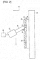
- Figure 2 is a schematic overview illustrating the screen printing apparatus 100 according to the present embodiment.
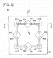
- Figure 3 is an upper surface view of the metal mask 50 according to the present embodiment.
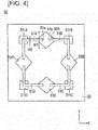
- Figure 4 is a lower surface view of the metal mask 50 according to the present embodiment.
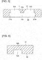
- Figure 5 is a cross-sectional view along line 5-5 of Figure 3 .
- Figure 6 is a cross-sectional view along line 6-6 of Figure 3 .
- Figure 2 only the metal mask 50 is illustrated in cross section for the sake of clarity.
- the screen printing apparatus 100 comprises a metal mask 50 that is disposed spaced apart on the separator 31 and in which a plurality of openings 51 are formed, and a squeegee 60 that is provided slidably with respect to the metal mask 50, as illustrated in Figure 2 .
- the screen printing apparatus 100 further comprises a mounting table 70 on which the separator 31 is mounted and a moving unit 80 that moves a support portion 61, which supports the squeegee 60, in the separator 31 plane (XY) direction as well as in the Z direction that is perpendicular to the direction of the plane.
- the moving unit 80 is, for example, an XYZ stage.
- the squeegee 60 is moved while sliding on the surface of the metal mask 50 by the moving unit. As a result, the gasket 41 is pushed out from the opening 51 of the metal mask 50 and applied onto the separator 31.
- the squeegee 60 is formed from rubber, for example.
- the metal mask 50 comprises four openings 51A-51D, as is illustrated in Figure 3- Figure 6 .
- the four openings 51A-51D are each formed with an L-shape.
- the metal mask 50 comprises bridge portions 52A-52D that are disposed between each of the openings 51A-51D and that are recessed from the lower surface S2. More specifically, the bridge portion 52A is provided between the opening 51A and the opening 51B; the bridge portion 52B is provided between the opening 51B and the opening 51C; the bridge portion 52C is provided between the opening 51C and the opening 51D; and the bridge portion 52D is provided between the opening 51D and the opening 51A.
- the bridge portions 52A-52D are provided in order to form a closed pattern gasket 41 on the separator 31 after screen printing.
- the metal mask 50 comprises filling portions 53A-53D that are provided on the lower surface S2 sides of the bridge portions 52A-52D, and in which are filled the gasket 41 by the sliding of the squeegee 60. Accordingly, by disposing the gasket 41 on the metal mask 50 and by the sliding of the squeegee 60, for example, from the right side to the left side in Figure 3 , the gasket 41 that has passed through the openings 51B, 51C fills the filling portion 53B. Furthermore, by the sliding of the squeegee 60, the gasket 41 fills the Filling portions 53A, 53C, and the filling portion 53D, in that order. Thus, it is possible to form a closed pattern of the gasket 41 on the separator 31.
- bridge portions 52A-52D have the same shape, only the configuration of the bridge portion 52A is described below, and the configurations of the bridge portions 52B-52D are omitted.
- filling portions 53A-53D have the same shape, only the configuration of the filling portion 53A is described below, and the configurations of the filling portions 53B-53D are omitted.
- the bridge portion 52A has a tapered shape so that the upper surface S1 side thereof becomes wider at the interface T between the openings 51A, 51B on the upper surface S1, as is illustrated in Figure 5 . According to this configuration, when the metal mask 50 is peeled off after the sliding of the squeegee 60, due to the tapered shape, it is possible to suppress the generation of angular edges on the gasket 41 and to reduce coating variability.
- the bridge portion 52A is preferably provided with a plurality of fine through-holes that extend in the Z direction. According to this configuration, since the gasket 41 fills the filling portion 53A by means of the through-holes, it is possible to increase the application amount.
- the filling portion 53A communicates with the respective ends 51a, 51b of the opening 51A and the opening 51B, and, when viewed from the lower surface S2, the width W1 thereof in the Y direction, which is perpendicular to the X direction extending from the opening 51A to the opening 51B, is larger than the width W2 in the Y direction of the openings 51A, 51B, as is illustrated in Figure 4 .
- the filling portion 53A when viewed from the lower surface S2, has a shape that is wider at substantially the central position between the respective ends 51a, 51b of the opening 51A and the opening 51B, and that becomes narrower toward the respective ends 51 a, 51b, as is illustrated in Figure 4 .
- the openings 51A-51D have enlarged opening portions 511A-511D that open more widely at the areas that are bent in an L-shape than at the other areas, as is illustrated in Figures 3-5 .
- the enlarged opening portions 511A-511D are configured to open widely on the lower surface S2 side, as is illustrated in Figure 5 .
- the shape of the enlarged opening portions 511 A-511D is not limited thereto; the shape is not particularly limited as long as the shape opens more widely in the XY direction than at the other areas, as seen from the lower surface S2.
- Figure 7 is a perspective view illustrating the gasket 41 that is applied to the separator 31 using the metal mask 50 according to the present embodiment.
- Figure 7 illustrates the areas that are formed by the filling portion 53A, the bridge portion 52A, and the openings 51A, 51B of the metal mask 50.
- the gasket 41 that is formed on the separator 31 comprises a first main body portion 41A that corresponds to the opening 51A, a second main body portion 41B that corresponds to the opening 51B, and a connecting portion 41C that corresponds to the filling portion 53A.
- the gasket 41 further comprises a first edge portion 41D that corresponds to the enlarged opening portion 511A and a second edge portion 41E that corresponds to the enlarged opening portion 511B.
- the gasket 41 further comprises a tapered portion 41T that corresponds to the tapered interface T.
- the separator 31, on the surface of which is applied the gasket 41, is formed by the screen printing apparatus 100 described above. Additionally, a separator 32, on the surface of which is applied a gasket 42 that has the same configuration as the gasket 41, is prepared in a similar manner. Then, the separator 31 and the separator 32 are layered so that the gasket 41 and the gasket 42 are opposite each other, as illustrated in Figure 1 .
- the first main body portion 41A and the second main body portion 41B are compressed in the Z direction to become substantially equal in height with the connecting portion 41C, the first edge portion 41D and the second edge portion 41E.
- the width W3 of the connecting portion 41C in the Y direction is configured to be larger than the width W4 of the first main body portion 41A and the second main body portion 41B in the Y direction; therefore, compared to cases in which the widths are the same, as in the prior art, the internal space of the gasket 41 can be more reliably sealed. Therefore, it is possible to suitably prevent the leaking of fuel gas or the oxidant gas to the outside.
- first edge portion 41D and a second edge portion 41E are provided to the L-shaped corners of the gasket 41, it is possible to reinforce the corners where stress is concentrated and thereby to improve the strength of the gasket 41.
- the metal mask 50 is used for applying the gasket 41 to the separator 31 by the sliding of the squeegee 60.
- On the metal mask 50 are formed a plurality of openings 51, which extend from the upper surface S1 on the side on which is provided the squeegee 60 to the lower surface S2 on the side on which is provided the separator 31.
- the metal mask 50 comprises a bridge portion 52A that is disposed between the opening 51A and the opening 51B and that is recessed from the lower surface S2, and a filling portion 53A that is provided in the lower surface S2 side of the bridge portion 52A, and in which is filled the gasket 41 by the sliding of the squeegee 60.
- the filling portion 53A communicates with the respective ends 51a, 51b of the opening 51A and the opening 51B, and, when viewed from the lower surface S2, the width W2 thereof in the Y direction that intersects the X direction extending from the opening 51A to the opening 51B is larger than the width W1 in the Y direction of the openings 51A, 51B.
- a pattern of the gasket 41 that is applied to the surface of the separator 31, in the area where the thickness in the Z direction is thin corresponding to the area where the bridge portion 52A is provided (corresponding to the connecting portion 41C), is formed that is wider than the other areas in the Y direction. Therefore, it is possible to prevent problems caused by a small application amount of the gasket 41 that is applied to the separator 31.
- the bridge portion 52A has a tapered shape so that the upper surface S I side thereof becomes wider at the interface T between the openings 51A, 51B on the upper surface S1. Accordingly, it is possible to suppress the generation of angular edges on the gasket 41 caused by the shearing force generated when the metal mask 50 is peeled off after the sliding of the squeegee 60, allowing a reduction in coating variability. Additionally, air is moved in a direction away from the gasket 41 along the tapered shape when laminating the separators 31, 32; therefore, air does not tend to enter the gasket 41, so that the risk of leakage is reduced.
- the opening 51A has an enlarged opening portion 511A that opens more widely than at the other portions. Therefore, a pattern is formed in the first edge portion 41D of the gasket 41, which corresponds to the enlarged opening portion 511A, that has a larger area in the XY direction than at the other portions. Therefore, it is possible to increase the application amount of the gasket 41 at the intended sites. As a result, it is possible to reinforce the desired position, and thereby to improve the strength of the gasket 41.
- the enlarged opening portion 511A is provided in the area where the opening 51A is bent. Accordingly, it is possible to reinforce the corners where stress concentrates, and thereby to improve the strength of the gasket 41.
- the screen printing apparatus 100 comprises the metal mask 50 described above. Accordingly, it is possible to suitably prevent the generation of gaps between the laminated gaskets 41, 42 and the leakage of gas to the outside.
- the screen printing apparatus 100 applies the gasket 41 to the surface of the separator 31. According to this screen printing apparatus 100, it is possible provide a fuel cell in which the generation of gaps between the laminated gaskets 41, 42 and the leakage of gas to the outside can be reliably prevented.
- the respective ends 51a, 51b of the openings 51A, 51B are extended along the Y direction, as is illustrated in Figure 4 .
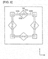
- the interface (ends 151a, 151b) of a bridge portion 152 with respect to openings 151A, 151B can be tilted relative to the Y direction as seen from the lower surface S2, and the end 151a and the end 151b can be arranged so as to be wrapped in the Y direction, as is illustrated in Figure 8 .
- the distance between the ends 151a, 151b can be reduced, it is possible to more reliably prevent the generation of gaps between the laminated gaskets 41, 42 and the leakage of gas to the outside.
- each of the bridge portions 52A-52D has the same shape, and each of the filling portions 53A-53D has the same shape.
- the shapes can be different from each other within a range that allows the effects of the present invention to be imparted.
- the bridge portion 52A has a tapered shape so that the upper surface S1 side thereof becomes wider at the interface T between the openings 51A, 51B on the upper surface S1.
- the interface T can be R-shaped so that the upper surface S1 side becomes wider.
- the enlarged opening portions 511A-511D are provided at the corners of the openings 51A-51D.
- the enlarged opening portions can be provided anywhere.
- the filling portion 53A has a shape that is wider at substantially the central position between the respective ends 51a, 51b of the opening 51A and the opening 51B and that becomes narrower toward the respective ends 51a, 51b.
- the width of the filling portion in the Y direction need only be larger than the width of the openings in the Y direction.
- screen printing is carried out by placing the gasket 41 on the upper surface of the metal mask 50 and pressing and sliding the squeegee 60 over the separator 31.
- screen printing can be carried out by the sliding of the squeegee 60 after flattening the gasket 41 on the upper surface of the metal mask 50 using a scraper before the sliding of the squeegee 60.
- the metal mask was used in a method to apply the gasket 41 on the separator 31 as the screen printing method; however, no limitation is thereby implied; the metal mask can be used with any screen printing apparatus.
Landscapes
- Engineering & Computer Science (AREA)
- Manufacturing & Machinery (AREA)
- Mechanical Engineering (AREA)
- Electrochemistry (AREA)
- Life Sciences & Earth Sciences (AREA)
- Sustainable Development (AREA)
- Sustainable Energy (AREA)
- Chemical & Material Sciences (AREA)
- Chemical Kinetics & Catalysis (AREA)
- General Chemical & Material Sciences (AREA)
- Microelectronics & Electronic Packaging (AREA)
- Fuel Cell (AREA)
- Printing Plates And Materials Therefor (AREA)
- Screen Printers (AREA)
Abstract
Description
- The present invention relates to a metal mask and a screen printing apparatus.
- In recent years, in response to social demands and trends rooted in energy and environmental issues, fuel cells, which operate at normal temperature and from which high power density can be obtained, are gaining attention as sources of power for electric vehicles as well as stationary power sources. Because the product of the electrode reaction is primarily water, fuel cells can provide clean power generation systems with low impact on the global environment. Polymer electrolyte fuel cells (PEFC) in particular, due to their ability to operate at relatively low temperatures, are considered promising power sources for electric vehicles.
- A polymer electrolyte fuel cell comprises an electrolyte membrane, a catalyst layer formed on both sides of the electrolyte membrane, and a membrane electrode assembly (Membrane Electrode Assembly, hereinafter referred to as MEA) that has a gas diffusion layer (GDL), etc. A fuel cell is configured by layering a plurality of MEAs with interposed separators.
- The screen printing method is used in the manufacture of fuel cells and is a known technique in which an adhesive is applied in a rectangular shape, forming a gasket on the surface of the separator.
- In the screen printing method, a separator as the object to be printed is disposed separated on the lower surface of a metal mask provided with openings, a gasket as a printing material is placed on the upper surface of the metal mask, and a squeegee is pressed and slid over the separator. Accordingly, the gasket is passed through the openings provided in the metal mask, and the gasket is applied onto the surface of the separator by transfer molding.
- In a subsequent step, the separator, on the surface of which the gasket is applied, is pressurized and laminated with another separator so that the gaskets face each other. At this time, if there is a gap between the laminated gaskets, there is the risk that fuel gas or oxidant gas will leak through the gap to the outside. It is therefore necessary to form a closed rectangular pattern on the gasket that is applied to the surface of the separator.
- In relation to the foregoing, for example, in
Patent Document 1, described below, a surface on one side of a bridge that is disposed between a pair of openings is aligned with a surface on the side over which the squeegee is slid, and the surface of the other side of the bridge is recessed from the back surface on the side that is opposite the side on which the squeegee is slid. The bridge is provided so at to connect the pair of openings. According to this metal mask, the gasket is filled in the recess provided on the other side surface of the bridge along with the openings by the sliding of the squeegee; therefore, it is possible to apply the gasket having a continuous closed pattern on the surface of the separator. - Patent Document 1: Japanese Laid Open Patent Application No.
2007-331195 - However, in the metal mask disclosed in
Patent Document 1, since the other side surface of the bridge is recessed from the back surface, the thickness of the printing material that is applied to the surface of the object to be printed becomes thin in the height direction, in the area that corresponds to the bridge. Furthermore, this area where the thickness is thin has the same width as the other areas in a direction that is perpendicular to the direction that connects the pair of openings. Therefore, there is the risk that problems will occur, due to the application amount being small. An example of a problem is, as described above, when the object to be printed is layered in a subsequent step, a gap forms at this area where the thickness is thinner, and gas leaks to the outside through the gap. - In order to solve the problem described above, the present invention provides a metal mask and a screen printing apparatus that are capable of preventing problems caused by the small application amount of printing material that is applied to the object to be printed.
- The metal mask according to the present invention that achieves the object described above is used to apply printing materials to an object to be printed by the sliding of a squeegee. The metal mask is a metal mask for screen printing on which are formed a plurality of openings that pass through from a first surface on a side to which the squeegee is provided to a second surface on a side to which the object to be printed is provided. The metal mask comprises a bridge portion that is disposed between one of the openings and the other of the openings, and that is recessed from the second surface. The metal mask comprises a filling portion that is provided on the second surface side of the bridge portion, and in which is filled the printing material by the sliding of the squeegee. The filling portion communicates with the respective ends of the one opening and the other opening and, when viewed from the second surface, has a width in a second direction that intersects a first direction extending from the one opening to the other opening that is larger than the width of the openings in the second direction.
- In addition, the screen printing apparatus according to the present invention that achieves the object above is a screen printing apparatus that has the metal mask described above.
- According to the metal mask and the screen printing apparatus configured as described above, of the printing material that is applied to the surface of the object to be printed, in the area where the thickness in the height direction is thin corresponding to the area where the bridge portion is provided, a pattern is formed that is wider than in the other areas in the second direction. Therefore, it is possible to prevent problems caused by the small application amount of printing material that is applied to the object to be printed. Specifically, when such objects to be printed are laminated one on top of another, since the printing material is formed wide in the second direction in the area where the height direction thickness is thin, it is possible to more reliably seal the internal space of the printing material. Therefore, it is possible to provide a metal mask and a screen printing apparatus that are well able to prevent the generation of gaps between laminated printing materials and the leaking of gas to the outside.
-
- [
Figure 1 ] is a cross-sectional view illustrating the cell structure of a fuel cell. - [
Figure 2 ] is a schematic overview illustrating the screen printing apparatus according to the present embodiment. - [
Figure 3 ] is an upper surface view of the metal mask according to the present embodiment. - [
Figure 4 ] is a lower surface view of the metal mask according to the present embodiment. - [
Figure 5 ] is a cross-sectional view along line 5-5 ofFigure 3 . - [
Figure 6 ] is a cross-sectional view along line 6-6 ofFigure 3 . - [
Figure 7 ] is a perspective view illustrating the gasket that is applied to the surface of the separator. - [
Figure 8 ] is a lower surface view of the metal mask according to a modified example. - Embodiments of the present invention will be explained below, with reference to the appended drawings. In the explanations of the drawings, the same elements are given the same reference signs, and redundant explanations are omitted. The dimensional ratios in the drawings are exaggerated for the sake of convenience of the explanation, and are different than the actual ratios.
-
Figure 1 is a cross-sectional view illustrating the cell structure of a fuel cell. - A
single cell 10 is applied to a polymer electrolyte fuel cell (PEFC), and the like, which uses hydrogen as fuel, and comprises anMEA 20, a pair ofseparators gaskets Figure 1 . - The
MEA 20 comprises apolymer electrolyte membrane 21, a pair ofcatalyst layer - The
catalyst layer 22 comprises a catalyst component, a conductive catalyst carrier that supports the catalyst component and polymer electrolytes; and is an anode catalyst layer in which the oxidative reaction of hydrogen progresses, and is disposed on one side of theelectrolyte membrane 21. - The
catalyst layer 23 comprises a catalyst component, a conductive catalyst carrier that supports the catalyst component and polymer electrolytes; and is a cathode catalyst layer in which the reductive reaction of oxygen progresses, and is disposed on the other side of theelectrolyte membrane 21. - The
electrolyte membrane 21 has a function of selectively transmitting protons generated in thecatalyst layer 22 to thecatalyst layer 23, and a function of acting as a barrier to prevent fuel gas that is supplied to the anode side and the oxidant gas that is supplied to the cathode side from mixing. - The
gas diffusion layer 24 is an anode gas diffusion layer for dispersing the fuel gas that is supplied to the anode side, and is positioned between theseparator 31 and thecatalyst layer 22. - The
gas diffusion layer 25 is a cathode gas diffusion layer for dispersing the oxidant gas that is supplied to the cathode side, and is positioned between theseparator 32 and thecatalyst layer 23. - The
separators single cells 10 in series, and a function of acting as a barrier to mutually block the fuel gas, the oxidant gas, and the refrigerant from each other. Theseparators - The
separator 31 is an anode separator that is disposed on the anode side of theMEA 20, and comprises agroove portion 31a that faces thecatalyst layer 22 and that configures a gas flow channel that is positioned between theMEA 20 and theseparator 31. Thegroove portion 31a is used to supply fuel gas to thecatalyst layer 22. - The
separator 32 is a cathode separator that is disposed on the cathode side of theMEA 20, and comprises agroove portion 32a that faces thecatalyst layer 23 and that configures a gas flow channel that is positioned between theMEA 20 and theseparator 32. Thegroove portion 32a is used to supply oxidant gas to thecatalyst layer 23. - The
gaskets electrolyte membrane 21. Thegaskets - The
gasket 41 is applied to surround the catalyst layer 22 (and the gas diffusion layer 24), and has a function of preventing the fuel gas that is supplied to thecatalyst layer 22 from leaking to the outside. - The
gasket 42 is applied to surround the catalyst layer 23 (and the gas diffusion layer 25), and has a function of preventing the oxidant gas that is supplied to thecatalyst layer 23 from leaking to the outside. - Next, the material and the size of each component member will be described.
- For the
electrolyte membrane 21, fluorine-based electrolyte membranes composed of perfluorocarbon sulfonic acid polymers, hydrocarbon-based electrolyte membranes having a sulfonic acid group, and porous membranes impregnated with electrolyte components, such as phosphoric acid and ionic liquid. Examples of the perfluorocarbon sulfonic acid polymers include Nafion (registered trademark, DuPont Co., Ltd.), Aciplex (registered trademark, Asahi Kasei Corporation), and Flemion (registered trademark, Asahi Glass Co., Ltd.) can be used. The porous membrane is formed from, for example, polytetratluoroethylene (PTFE) or polyvinylidene-fluoride (PVDF). - The thickness of the
electrolyte membrane 21 is not particularly limited, but is preferably 5-300 µm, and more preferably 10-200 µm, from the standpoint of strength, durability, and output characteristics. - The catalyst component that is used for the catalyst layer (cathode catalyst layer) 23 is not particularly limited and can be any component that has a catalytic effect in the reductive reaction of oxygen. The catalyst component that is used for the catalyst layer (anode catalyst layer) 22 is not particularly limited and can be any component that has a catalytic effect in the oxidative reaction of hydrogen.
- Specific catalyst components are selected from such metals as platinum, ruthenium, iridium, rhodium, palladium, osmium, tungsten, lead, iron, chromium, cobalt, nickel, manganese, vanadium, molybdenum, gallium, and aluminum, and alloys thereof, etc. It is preferable to include at least platinum in order to improve catalytic activity, resistance to poisoning from carbon monoxide, heat resistance, and the like. The catalyst components that are applied to the cathode catalyst layer and the anode catalyst layer need not be the same, and can be appropriately changed.
- The conductive carrier of the catalyst that is used for the catalyst layers 22, 23 is not particularly limited as long as the catalyst carrier has a specific surface area for supporting the catalyst component in the desired dispersed state, and sufficient electronic conductivity as a current collector. The carbon particles can be composed of carbon black, activated carbon, coke, natural graphite, or artificial graphite, for example.
- The polymer electrolyte that is used for the catalyst layers 22, 23 is not particularly limited as long the member has at least a high proton conductivity; for example, fluorine-based electrolytes containing fluorine atoms in all or part of the polymer backbone, or hydrocarbon electrolytes that do not contain fluorine atoms in the polymer backbone can be used. The polymer electrolytes used for the catalyst layers 22, 23 can be the same as or different from the polymer electrolytes used for the
electrolyte membrane 21, but are preferably the same from the standpoint of improving the adhesion of catalyst layers 22, 23 with respect to theelectrolyte membrane 21. - The thickness of the catalyst layer is not particularly limited as long as the thickness is sufficient to exert the catalytic effect of the oxidative reaction of hydrogen (anode side) and the reductive reaction of oxygen (cathode side), and conventional thicknesses can be used. Specifically, the thickness of each catalyst layer is preferably 1-20 µm.
- The gas diffusion layers 24, 25 is configured from a sheet material having conductivity and porosity, such as carbon fabric such as glassy carbon, a paper-like paper body, felt, and nonwoven fabric. The thickness of the substrate is not particularly limited, but is preferably 30-500 µm, from the standpoint of mechanical strength and permeability of gas, water, and the like. The gas diffusion layers 24, 25 preferably contain a water-repellent agent in the substrate, from the standpoint of water repellency and suppression of the flooding phenomenon. Examples of water-repellent agents include fluorine-based polymer material such as PTFE, PVDF, poly hexafluoropropylene, and tetrafluoroethylene-hexafluoropropylene copolymers (FEP), polypropylene, and polyethylene.
- The
separators groove portions - The
gaskets gaskets - Next, the screen printing apparatus 100 for applying a gasket (corresponding to the printing material) 41 onto the separator (object to be printed) 31 of the present embodiment and the
metal mask 50 that configures the screen printing apparatus 100 will be described with reference toFigure 2-Figure 6 . -
Figure 2 is a schematic overview illustrating the screen printing apparatus 100 according to the present embodiment.Figure 3 is an upper surface view of themetal mask 50 according to the present embodiment.Figure 4 is a lower surface view of themetal mask 50 according to the present embodiment.Figure 5 is a cross-sectional view along line 5-5 ofFigure 3 .Figure 6 is a cross-sectional view along line 6-6 ofFigure 3 . InFigure 2 , only themetal mask 50 is illustrated in cross section for the sake of clarity. - The screen printing apparatus 100 comprises a
metal mask 50 that is disposed spaced apart on theseparator 31 and in which a plurality ofopenings 51 are formed, and asqueegee 60 that is provided slidably with respect to themetal mask 50, as illustrated inFigure 2 . The screen printing apparatus 100 further comprises a mounting table 70 on which theseparator 31 is mounted and a movingunit 80 that moves asupport portion 61, which supports thesqueegee 60, in the separator 31 plane (XY) direction as well as in the Z direction that is perpendicular to the direction of the plane. The movingunit 80 is, for example, an XYZ stage. - The
squeegee 60 is moved while sliding on the surface of themetal mask 50 by the moving unit. As a result, thegasket 41 is pushed out from theopening 51 of themetal mask 50 and applied onto theseparator 31. Thesqueegee 60 is formed from rubber, for example. - The
metal mask 50 comprises fouropenings 51A-51D, as is illustrated inFigure 3-Figure 6 . The fouropenings 51A-51D are each formed with an L-shape. - The
metal mask 50 comprisesbridge portions 52A-52D that are disposed between each of theopenings 51A-51D and that are recessed from the lower surface S2. More specifically, thebridge portion 52A is provided between theopening 51A and theopening 51B; thebridge portion 52B is provided between the opening 51B and theopening 51C; thebridge portion 52C is provided between theopening 51C and theopening 51D; and thebridge portion 52D is provided between theopening 51D and theopening 51A. Thebridge portions 52A-52D are provided in order to form aclosed pattern gasket 41 on theseparator 31 after screen printing. - The
metal mask 50 comprises fillingportions 53A-53D that are provided on the lower surface S2 sides of thebridge portions 52A-52D, and in which are filled thegasket 41 by the sliding of thesqueegee 60. Accordingly, by disposing thegasket 41 on themetal mask 50 and by the sliding of thesqueegee 60, for example, from the right side to the left side inFigure 3 , thegasket 41 that has passed through theopenings portion 53B. Furthermore, by the sliding of thesqueegee 60, thegasket 41 fills the Fillingportions portion 53D, in that order. Thus, it is possible to form a closed pattern of thegasket 41 on theseparator 31. - Since the
bridge portions 52A-52D have the same shape, only the configuration of thebridge portion 52A is described below, and the configurations of thebridge portions 52B-52D are omitted. In addition, since the fillingportions 53A-53D have the same shape, only the configuration of the fillingportion 53A is described below, and the configurations of the fillingportions 53B-53D are omitted. - The
bridge portion 52A has a tapered shape so that the upper surface S1 side thereof becomes wider at the interface T between theopenings Figure 5 . According to this configuration, when themetal mask 50 is peeled off after the sliding of thesqueegee 60, due to the tapered shape, it is possible to suppress the generation of angular edges on thegasket 41 and to reduce coating variability. - Although not shown, the
bridge portion 52A is preferably provided with a plurality of fine through-holes that extend in the Z direction. According to this configuration, since thegasket 41 fills the fillingportion 53A by means of the through-holes, it is possible to increase the application amount. - The filling
portion 53A communicates with the respective ends 51a, 51b of theopening 51A and theopening 51B, and, when viewed from the lower surface S2, the width W1 thereof in the Y direction, which is perpendicular to the X direction extending from theopening 51A to theopening 51B, is larger than the width W2 in the Y direction of theopenings Figure 4 . - The filling
portion 53A, when viewed from the lower surface S2, has a shape that is wider at substantially the central position between the respective ends 51a, 51b of theopening 51A and theopening 51B, and that becomes narrower toward the respective ends 51 a, 51b, as is illustrated inFigure 4 . - The
openings 51A-51D have enlarged openingportions 511A-511D that open more widely at the areas that are bent in an L-shape than at the other areas, as is illustrated inFigures 3-5 . Theenlarged opening portions 511A-511D are configured to open widely on the lower surface S2 side, as is illustrated inFigure 5 . The shape of the enlarged opening portions 511 A-511D is not limited thereto; the shape is not particularly limited as long as the shape opens more widely in the XY direction than at the other areas, as seen from the lower surface S2. - Next, the actions of the
metal mask 50 according to the present embodiment will be described with reference toFigure 7 . -
Figure 7 is a perspective view illustrating thegasket 41 that is applied to theseparator 31 using themetal mask 50 according to the present embodiment. For ease of understanding,Figure 7 illustrates the areas that are formed by the fillingportion 53A, thebridge portion 52A, and theopenings metal mask 50. - By the sliding of the
squeegee 60 in a state in which themetal mask 50, on the surface of which is disposed thegasket 41, is disposed on theseparator 31, thegasket 41 pattern illustrated inFigure 7 is formed on theseparator 31, as is illustrated inFigure 2 . - The
gasket 41 that is formed on theseparator 31 comprises a firstmain body portion 41A that corresponds to theopening 51A, a secondmain body portion 41B that corresponds to theopening 51B, and a connectingportion 41C that corresponds to the fillingportion 53A. Thegasket 41 further comprises afirst edge portion 41D that corresponds to theenlarged opening portion 511A and asecond edge portion 41E that corresponds to theenlarged opening portion 511B. Thegasket 41 further comprises a taperedportion 41T that corresponds to the tapered interface T. - The
separator 31, on the surface of which is applied thegasket 41, is formed by the screen printing apparatus 100 described above. Additionally, aseparator 32, on the surface of which is applied agasket 42 that has the same configuration as thegasket 41, is prepared in a similar manner. Then, theseparator 31 and theseparator 32 are layered so that thegasket 41 and thegasket 42 are opposite each other, as illustrated inFigure 1 . - At this time, since the
gasket 41 has a taperedportion 41T so that air tends to leak out, air tends not to enter thegasket 41, thereby reducing the risk of leakage. - By laminating the
separator 31 and theseparator 32, the firstmain body portion 41A and the secondmain body portion 41B are compressed in the Z direction to become substantially equal in height with the connectingportion 41C, thefirst edge portion 41D and thesecond edge portion 41E. - The width W3 of the connecting
portion 41C in the Y direction is configured to be larger than the width W4 of the firstmain body portion 41A and the secondmain body portion 41B in the Y direction; therefore, compared to cases in which the widths are the same, as in the prior art, the internal space of thegasket 41 can be more reliably sealed. Therefore, it is possible to suitably prevent the leaking of fuel gas or the oxidant gas to the outside. - In addition, since a
first edge portion 41D and asecond edge portion 41E are provided to the L-shaped corners of thegasket 41, it is possible to reinforce the corners where stress is concentrated and thereby to improve the strength of thegasket 41. - As described above, the
metal mask 50 according to the present embodiment is used for applying thegasket 41 to theseparator 31 by the sliding of thesqueegee 60. On themetal mask 50 are formed a plurality ofopenings 51, which extend from the upper surface S1 on the side on which is provided thesqueegee 60 to the lower surface S2 on the side on which is provided theseparator 31. Themetal mask 50 comprises abridge portion 52A that is disposed between theopening 51A and theopening 51B and that is recessed from the lower surface S2, and a fillingportion 53A that is provided in the lower surface S2 side of thebridge portion 52A, and in which is filled thegasket 41 by the sliding of thesqueegee 60. The fillingportion 53A communicates with the respective ends 51a, 51b of theopening 51A and theopening 51B, and, when viewed from the lower surface S2, the width W2 thereof in the Y direction that intersects the X direction extending from theopening 51A to theopening 51B is larger than the width W1 in the Y direction of theopenings gasket 41 that is applied to the surface of theseparator 31, in the area where the thickness in the Z direction is thin corresponding to the area where thebridge portion 52A is provided (corresponding to the connectingportion 41C), is formed that is wider than the other areas in the Y direction. Therefore, it is possible to prevent problems caused by a small application amount of thegasket 41 that is applied to theseparator 31. Specifically, whensuch separators gasket 41. Therefore, it is possible to suitably prevent the formation of gaps between thelaminated gaskets - In addition, the
bridge portion 52A has a tapered shape so that the upper surface S I side thereof becomes wider at the interface T between theopenings gasket 41 caused by the shearing force generated when themetal mask 50 is peeled off after the sliding of thesqueegee 60, allowing a reduction in coating variability. Additionally, air is moved in a direction away from thegasket 41 along the tapered shape when laminating theseparators gasket 41, so that the risk of leakage is reduced. - Furthermore, the
opening 51A has anenlarged opening portion 511A that opens more widely than at the other portions. Therefore, a pattern is formed in thefirst edge portion 41D of thegasket 41, which corresponds to theenlarged opening portion 511A, that has a larger area in the XY direction than at the other portions. Therefore, it is possible to increase the application amount of thegasket 41 at the intended sites. As a result, it is possible to reinforce the desired position, and thereby to improve the strength of thegasket 41. - In particular, the
enlarged opening portion 511A is provided in the area where theopening 51A is bent. Accordingly, it is possible to reinforce the corners where stress concentrates, and thereby to improve the strength of thegasket 41. - Additionally, the screen printing apparatus 100 comprises the
metal mask 50 described above. Accordingly, it is possible to suitably prevent the generation of gaps between thelaminated gaskets - Furthermore, the screen printing apparatus 100 according to the present embodiment applies the
gasket 41 to the surface of theseparator 31. According to this screen printing apparatus 100, it is possible provide a fuel cell in which the generation of gaps between thelaminated gaskets - Modified examples of the above-described embodiment are illustrated below.
- In the above-described embodiment, the respective ends 51a, 51b of the
openings Figure 4 . However, the interface (ends 151a, 151b) of abridge portion 152 with respect toopenings end 151a and theend 151b can be arranged so as to be wrapped in the Y direction, as is illustrated inFigure 8 . According to this configuration, since the distance between theends laminated gaskets - In addition, in the above-described embodiment, each of the
bridge portions 52A-52D has the same shape, and each of the fillingportions 53A-53D has the same shape. However, no limitation is thereby implied; the shapes can be different from each other within a range that allows the effects of the present invention to be imparted. - Furthermore, in the above-described embodiment, the
bridge portion 52A has a tapered shape so that the upper surface S1 side thereof becomes wider at the interface T between theopenings - In addition, in the above-described embodiment, the
enlarged opening portions 511A-511D are provided at the corners of theopenings 51A-51D. However, no limitation is thereby implied; the enlarged opening portions can be provided anywhere. - Additionally, in the above-described embodiment, the filling
portion 53A has a shape that is wider at substantially the central position between the respective ends 51a, 51b of theopening 51A and theopening 51B and that becomes narrower toward the respective ends 51a, 51b. However, no limitation is thereby implied; the width of the filling portion in the Y direction need only be larger than the width of the openings in the Y direction. - Furthermore, in the above-described embodiment, an embodiment was described in which screen printing is carried out by placing the
gasket 41 on the upper surface of themetal mask 50 and pressing and sliding thesqueegee 60 over theseparator 31. However, screen printing can be carried out by the sliding of thesqueegee 60 after flattening thegasket 41 on the upper surface of themetal mask 50 using a scraper before the sliding of thesqueegee 60. - Additionally, in the above-described embodiment, the metal mask was used in a method to apply the
gasket 41 on theseparator 31 as the screen printing method; however, no limitation is thereby implied; the metal mask can be used with any screen printing apparatus. -
- 20
- MEA,
- 31
- Separator (object to be printed),
- 41
- Gasket (printing material),
- 50
- Metal mask,
- 51A-51D, 151A, 151B
- Openings,
- 51a, 51b, 151a, 151b
- Ends of the openings,
- 511A-511D
- Enlarged opening portions,
- 52A-52D, 152
- Bridge portions,
- 53A-53D
- Filling portions,
- 60
- Squeegee,
- S1
- Upper surface (first surface),
- S2
- Lower surface (second surface),
- T
- Interface,
- W1
- Width of filling portion in the Y direction
- W2
- Width of opening in the Y direction
Claims (7)
- A metal mask for screen printing a printing material on an object to be printed by sliding of a squeegee thereon, and which are formed a plurality of openings that pass from a first surface on a side on which the squeegee is provided to a second surface on a side on which the object to be printed is provided, comprising:a bridge portion disposed between one of the openings and the other of the openings, and that is recessed from the second surface, anda filling portion provided on a second surface side of the bridge portion, and in which is filled the printing material by the sliding of the squeegee, whereinthe filling portion communicates with respective ends of the one opening and the other opening and, as seen from the second surface, has a width in a second direction that intersects a first direction extending from the one opening to the other opening that is greater than a width of the openings in the second direction.
- The metal mask according to claim 1, wherein the bridge portion has a tapered shape or an R-shape so that a first surface side becomes wider at an interface between the openings at the first surface.
- The metal mask according to claim 1 or 2, wherein the openings have enlarged opening portions that open more widely than at the other portions.
- The metal mask according to claim 3, wherein the enlarged opening portions are provided in areas where the openings are bent.
- The metal mask according to any one of claims 1 to 4, wherein an interface of the bridge portion with respect to the openings is tilted relative to the second direction in a plan view of the first plane, and the interface at one of the openings and the interface at the other of the openings are arranged so as to be wrapped in the second direction.
- A screen printing apparatus comprising the metal mask according to any one of claims 1 to 5.
- The screen printing apparatus according to claim 6, wherein the object to be printed is a separator of a fuel cell, and the printing material is an adhesive that forms a gasket that is applied to the separator.
Applications Claiming Priority (1)
| Application Number | Priority Date | Filing Date | Title |
|---|---|---|---|
| PCT/JP2014/063262 WO2015177850A1 (en) | 2014-05-19 | 2014-05-19 | Metal mask and screen printing apparatus |
Publications (3)
| Publication Number | Publication Date |
|---|---|
| EP3147133A1 true EP3147133A1 (en) | 2017-03-29 |
| EP3147133A4 EP3147133A4 (en) | 2017-07-12 |
| EP3147133B1 EP3147133B1 (en) | 2018-01-10 |
Family
ID=54553548
Family Applications (1)
| Application Number | Title | Priority Date | Filing Date |
|---|---|---|---|
| EP14892307.1A Not-in-force EP3147133B1 (en) | 2014-05-19 | 2014-05-19 | Metal mask and screen printing apparatus |
Country Status (6)
| Country | Link |
|---|---|
| US (1) | US9789682B2 (en) |
| EP (1) | EP3147133B1 (en) |
| JP (1) | JP6213671B2 (en) |
| CN (1) | CN106457869B (en) |
| CA (1) | CA2949452C (en) |
| WO (1) | WO2015177850A1 (en) |
Families Citing this family (6)
| Publication number | Priority date | Publication date | Assignee | Title |
|---|---|---|---|---|
| CN106585069A (en) * | 2016-12-23 | 2017-04-26 | 武汉华星光电技术有限公司 | Flexible substrate, panel and method of manufacturing flexible substrate and panel by screen printer |
| TWI663067B (en) * | 2018-08-07 | 2019-06-21 | 倉和股份有限公司 | Composite material screen plate and manufacturing method thereof |
| CN112519394A (en) * | 2020-11-19 | 2021-03-19 | 浙江硕克科技有限公司 | Precise circuit printing metal plate of semiconductor electronic component |
| JP7300545B1 (en) | 2022-08-29 | 2023-06-29 | 竹田東京プロセスサービス株式会社 | Screen mask manufacturing method and screen mask |
| DE102023205774A1 (en) * | 2023-06-21 | 2024-12-24 | Robert Bosch Gesellschaft mit beschränkter Haftung | Method for producing a seal on a layer or sheet of an electrochemical cell |
| TWI892371B (en) * | 2023-12-21 | 2025-08-01 | 倉和股份有限公司 | Printing screen to improve ink penetration |
Family Cites Families (9)
| Publication number | Priority date | Publication date | Assignee | Title |
|---|---|---|---|---|
| JPH05338370A (en) | 1992-06-10 | 1993-12-21 | Dainippon Screen Mfg Co Ltd | Metal mask plate for screen printing |
| US7070876B2 (en) * | 2003-03-24 | 2006-07-04 | Ballard Power Systems, Inc. | Membrane electrode assembly with integrated seal |
| JP4873935B2 (en) * | 2005-11-15 | 2012-02-08 | タイガースポリマー株式会社 | Method of molding rubber packing for fuel cell |
| JP2007331195A (en) | 2006-06-14 | 2007-12-27 | Dainippon Printing Co Ltd | Metal mask and printing method using the metal mask |
| JP2007331194A (en) * | 2006-06-14 | 2007-12-27 | Dainippon Printing Co Ltd | Metal mask and printing method using the metal mask |
| JP2009226924A (en) * | 2008-02-27 | 2009-10-08 | Kyocera Corp | Printing mask, method for manufacturing the same, printing method using the printing mask, and method for manufacturing wiring board |
| CN102712193B (en) * | 2009-09-21 | 2016-06-01 | Dtg国际有限公司 | Printing screen and manufacture method thereof |
| NL2003627C2 (en) * | 2009-10-12 | 2011-04-13 | Stork Prints Bv | Screen printing. |
| JP2011201054A (en) * | 2010-03-24 | 2011-10-13 | Panasonic Corp | Device and method for printing screen |
-
2014
- 2014-05-19 US US15/305,142 patent/US9789682B2/en not_active Expired - Fee Related
- 2014-05-19 CA CA2949452A patent/CA2949452C/en active Active
- 2014-05-19 CN CN201480078981.XA patent/CN106457869B/en not_active Expired - Fee Related
- 2014-05-19 EP EP14892307.1A patent/EP3147133B1/en not_active Not-in-force
- 2014-05-19 JP JP2016520829A patent/JP6213671B2/en not_active Expired - Fee Related
- 2014-05-19 WO PCT/JP2014/063262 patent/WO2015177850A1/en not_active Ceased
Also Published As
| Publication number | Publication date |
|---|---|
| CN106457869A (en) | 2017-02-22 |
| JP6213671B2 (en) | 2017-10-18 |
| EP3147133A4 (en) | 2017-07-12 |
| EP3147133B1 (en) | 2018-01-10 |
| CA2949452A1 (en) | 2015-11-26 |
| JPWO2015177850A1 (en) | 2017-04-20 |
| US9789682B2 (en) | 2017-10-17 |
| CA2949452C (en) | 2018-06-05 |
| CN106457869B (en) | 2018-04-10 |
| US20170036434A1 (en) | 2017-02-09 |
| WO2015177850A1 (en) | 2015-11-26 |
Similar Documents
| Publication | Publication Date | Title |
|---|---|---|
| EP1403949B1 (en) | Catalyst-coated ionomer membrane with protective film layer and membrane-electrode-assembly made thereof | |
| EP1399983B1 (en) | Membrane-electrode assembly for polymeric membrane fuel cells | |
| CA2880160C (en) | Fuel-cell gasket, fuel-cell bonded assembly, and sheet-member bonding method | |
| EP3147133B1 (en) | Metal mask and screen printing apparatus | |
| US9352549B2 (en) | Screen printing apparatus and screen printing method | |
| EP1792359A2 (en) | Membrane electrode assembly | |
| EP2112705A1 (en) | Film-film reinforcing member bonded body, film-catalyst layer bonded body, film-electrode bonded body, and polyelectrolyte type fuel cell | |
| JP5838570B2 (en) | Membrane electrode assembly in polymer electrolyte fuel cell | |
| EP2874219B1 (en) | Membrane electrode assembly | |
| JP5101185B2 (en) | Membrane-membrane reinforcing member assembly, membrane-catalyst layer assembly, membrane-electrode assembly, and polymer electrolyte fuel cell | |
| JP5583276B2 (en) | Direct oxidation fuel cell |
Legal Events
| Date | Code | Title | Description |
|---|---|---|---|
| PUAI | Public reference made under article 153(3) epc to a published international application that has entered the european phase |
Free format text: ORIGINAL CODE: 0009012 |
|
| 17P | Request for examination filed |
Effective date: 20161216 |
|
| AK | Designated contracting states |
Kind code of ref document: A1 Designated state(s): AL AT BE BG CH CY CZ DE DK EE ES FI FR GB GR HR HU IE IS IT LI LT LU LV MC MK MT NL NO PL PT RO RS SE SI SK SM TR |
|
| AX | Request for extension of the european patent |
Extension state: BA ME |
|
| A4 | Supplementary search report drawn up and despatched |
Effective date: 20170609 |
|
| RIC1 | Information provided on ipc code assigned before grant |
Ipc: H01M 8/00 20160101ALI20170602BHEP Ipc: H05K 3/12 20060101ALI20170602BHEP Ipc: B41F 15/36 20060101ALI20170602BHEP Ipc: B41N 1/24 20060101AFI20170602BHEP Ipc: B41C 1/14 20060101ALI20170602BHEP |
|
| DAX | Request for extension of the european patent (deleted) | ||
| GRAP | Despatch of communication of intention to grant a patent |
Free format text: ORIGINAL CODE: EPIDOSNIGR1 |
|
| INTG | Intention to grant announced |
Effective date: 20170907 |
|
| GRAS | Grant fee paid |
Free format text: ORIGINAL CODE: EPIDOSNIGR3 |
|
| GRAA | (expected) grant |
Free format text: ORIGINAL CODE: 0009210 |
|
| AK | Designated contracting states |
Kind code of ref document: B1 Designated state(s): AL AT BE BG CH CY CZ DE DK EE ES FI FR GB GR HR HU IE IS IT LI LT LU LV MC MK MT NL NO PL PT RO RS SE SI SK SM TR |
|
| REG | Reference to a national code |
Ref country code: CH Ref legal event code: EP Ref country code: AT Ref legal event code: REF Ref document number: 961945 Country of ref document: AT Kind code of ref document: T Effective date: 20180115 |
|
| REG | Reference to a national code |
Ref country code: IE Ref legal event code: FG4D |
|
| REG | Reference to a national code |
Ref country code: DE Ref legal event code: R096 Ref document number: 602014019954 Country of ref document: DE |
|
| REG | Reference to a national code |
Ref country code: NL Ref legal event code: MP Effective date: 20180110 |
|
| REG | Reference to a national code |
Ref country code: FR Ref legal event code: PLFP Year of fee payment: 5 |
|
| REG | Reference to a national code |
Ref country code: AT Ref legal event code: MK05 Ref document number: 961945 Country of ref document: AT Kind code of ref document: T Effective date: 20180110 |
|
| PG25 | Lapsed in a contracting state [announced via postgrant information from national office to epo] |
Ref country code: NL Free format text: LAPSE BECAUSE OF FAILURE TO SUBMIT A TRANSLATION OF THE DESCRIPTION OR TO PAY THE FEE WITHIN THE PRESCRIBED TIME-LIMIT Effective date: 20180110 |
|
| PG25 | Lapsed in a contracting state [announced via postgrant information from national office to epo] |
Ref country code: FI Free format text: LAPSE BECAUSE OF FAILURE TO SUBMIT A TRANSLATION OF THE DESCRIPTION OR TO PAY THE FEE WITHIN THE PRESCRIBED TIME-LIMIT Effective date: 20180110 Ref country code: HR Free format text: LAPSE BECAUSE OF FAILURE TO SUBMIT A TRANSLATION OF THE DESCRIPTION OR TO PAY THE FEE WITHIN THE PRESCRIBED TIME-LIMIT Effective date: 20180110 Ref country code: NO Free format text: LAPSE BECAUSE OF FAILURE TO SUBMIT A TRANSLATION OF THE DESCRIPTION OR TO PAY THE FEE WITHIN THE PRESCRIBED TIME-LIMIT Effective date: 20180410 Ref country code: ES Free format text: LAPSE BECAUSE OF FAILURE TO SUBMIT A TRANSLATION OF THE DESCRIPTION OR TO PAY THE FEE WITHIN THE PRESCRIBED TIME-LIMIT Effective date: 20180110 Ref country code: LT Free format text: LAPSE BECAUSE OF FAILURE TO SUBMIT A TRANSLATION OF THE DESCRIPTION OR TO PAY THE FEE WITHIN THE PRESCRIBED TIME-LIMIT Effective date: 20180110 Ref country code: CY Free format text: LAPSE BECAUSE OF FAILURE TO SUBMIT A TRANSLATION OF THE DESCRIPTION OR TO PAY THE FEE WITHIN THE PRESCRIBED TIME-LIMIT Effective date: 20180110 |
|
| PG25 | Lapsed in a contracting state [announced via postgrant information from national office to epo] |
Ref country code: BG Free format text: LAPSE BECAUSE OF FAILURE TO SUBMIT A TRANSLATION OF THE DESCRIPTION OR TO PAY THE FEE WITHIN THE PRESCRIBED TIME-LIMIT Effective date: 20180410 Ref country code: PL Free format text: LAPSE BECAUSE OF FAILURE TO SUBMIT A TRANSLATION OF THE DESCRIPTION OR TO PAY THE FEE WITHIN THE PRESCRIBED TIME-LIMIT Effective date: 20180110 Ref country code: IS Free format text: LAPSE BECAUSE OF FAILURE TO SUBMIT A TRANSLATION OF THE DESCRIPTION OR TO PAY THE FEE WITHIN THE PRESCRIBED TIME-LIMIT Effective date: 20180510 Ref country code: GR Free format text: LAPSE BECAUSE OF FAILURE TO SUBMIT A TRANSLATION OF THE DESCRIPTION OR TO PAY THE FEE WITHIN THE PRESCRIBED TIME-LIMIT Effective date: 20180411 Ref country code: LV Free format text: LAPSE BECAUSE OF FAILURE TO SUBMIT A TRANSLATION OF THE DESCRIPTION OR TO PAY THE FEE WITHIN THE PRESCRIBED TIME-LIMIT Effective date: 20180110 Ref country code: SE Free format text: LAPSE BECAUSE OF FAILURE TO SUBMIT A TRANSLATION OF THE DESCRIPTION OR TO PAY THE FEE WITHIN THE PRESCRIBED TIME-LIMIT Effective date: 20180110 Ref country code: RS Free format text: LAPSE BECAUSE OF FAILURE TO SUBMIT A TRANSLATION OF THE DESCRIPTION OR TO PAY THE FEE WITHIN THE PRESCRIBED TIME-LIMIT Effective date: 20180110 Ref country code: AT Free format text: LAPSE BECAUSE OF FAILURE TO SUBMIT A TRANSLATION OF THE DESCRIPTION OR TO PAY THE FEE WITHIN THE PRESCRIBED TIME-LIMIT Effective date: 20180110 |
|
| REG | Reference to a national code |
Ref country code: DE Ref legal event code: R097 Ref document number: 602014019954 Country of ref document: DE |
|
| PG25 | Lapsed in a contracting state [announced via postgrant information from national office to epo] |
Ref country code: EE Free format text: LAPSE BECAUSE OF FAILURE TO SUBMIT A TRANSLATION OF THE DESCRIPTION OR TO PAY THE FEE WITHIN THE PRESCRIBED TIME-LIMIT Effective date: 20180110 Ref country code: IT Free format text: LAPSE BECAUSE OF FAILURE TO SUBMIT A TRANSLATION OF THE DESCRIPTION OR TO PAY THE FEE WITHIN THE PRESCRIBED TIME-LIMIT Effective date: 20180110 Ref country code: AL Free format text: LAPSE BECAUSE OF FAILURE TO SUBMIT A TRANSLATION OF THE DESCRIPTION OR TO PAY THE FEE WITHIN THE PRESCRIBED TIME-LIMIT Effective date: 20180110 Ref country code: RO Free format text: LAPSE BECAUSE OF FAILURE TO SUBMIT A TRANSLATION OF THE DESCRIPTION OR TO PAY THE FEE WITHIN THE PRESCRIBED TIME-LIMIT Effective date: 20180110 |
|
| PLBE | No opposition filed within time limit |
Free format text: ORIGINAL CODE: 0009261 |
|
| STAA | Information on the status of an ep patent application or granted ep patent |
Free format text: STATUS: NO OPPOSITION FILED WITHIN TIME LIMIT |
|
| PG25 | Lapsed in a contracting state [announced via postgrant information from national office to epo] |
Ref country code: CZ Free format text: LAPSE BECAUSE OF FAILURE TO SUBMIT A TRANSLATION OF THE DESCRIPTION OR TO PAY THE FEE WITHIN THE PRESCRIBED TIME-LIMIT Effective date: 20180110 Ref country code: SM Free format text: LAPSE BECAUSE OF FAILURE TO SUBMIT A TRANSLATION OF THE DESCRIPTION OR TO PAY THE FEE WITHIN THE PRESCRIBED TIME-LIMIT Effective date: 20180110 Ref country code: SK Free format text: LAPSE BECAUSE OF FAILURE TO SUBMIT A TRANSLATION OF THE DESCRIPTION OR TO PAY THE FEE WITHIN THE PRESCRIBED TIME-LIMIT Effective date: 20180110 Ref country code: DK Free format text: LAPSE BECAUSE OF FAILURE TO SUBMIT A TRANSLATION OF THE DESCRIPTION OR TO PAY THE FEE WITHIN THE PRESCRIBED TIME-LIMIT Effective date: 20180110 |
|
| REG | Reference to a national code |
Ref country code: CH Ref legal event code: PL |
|
| 26N | No opposition filed |
Effective date: 20181011 |
|
| REG | Reference to a national code |
Ref country code: BE Ref legal event code: MM Effective date: 20180531 |
|
| PG25 | Lapsed in a contracting state [announced via postgrant information from national office to epo] |
Ref country code: MC Free format text: LAPSE BECAUSE OF FAILURE TO SUBMIT A TRANSLATION OF THE DESCRIPTION OR TO PAY THE FEE WITHIN THE PRESCRIBED TIME-LIMIT Effective date: 20180110 |
|
| REG | Reference to a national code |
Ref country code: IE Ref legal event code: MM4A |
|
| PG25 | Lapsed in a contracting state [announced via postgrant information from national office to epo] |
Ref country code: CH Free format text: LAPSE BECAUSE OF NON-PAYMENT OF DUE FEES Effective date: 20180531 Ref country code: SI Free format text: LAPSE BECAUSE OF FAILURE TO SUBMIT A TRANSLATION OF THE DESCRIPTION OR TO PAY THE FEE WITHIN THE PRESCRIBED TIME-LIMIT Effective date: 20180110 Ref country code: LI Free format text: LAPSE BECAUSE OF NON-PAYMENT OF DUE FEES Effective date: 20180531 |
|
| PG25 | Lapsed in a contracting state [announced via postgrant information from national office to epo] |
Ref country code: LU Free format text: LAPSE BECAUSE OF NON-PAYMENT OF DUE FEES Effective date: 20180519 |
|
| PG25 | Lapsed in a contracting state [announced via postgrant information from national office to epo] |
Ref country code: IE Free format text: LAPSE BECAUSE OF NON-PAYMENT OF DUE FEES Effective date: 20180519 |
|
| PG25 | Lapsed in a contracting state [announced via postgrant information from national office to epo] |
Ref country code: BE Free format text: LAPSE BECAUSE OF NON-PAYMENT OF DUE FEES Effective date: 20180531 |
|
| PG25 | Lapsed in a contracting state [announced via postgrant information from national office to epo] |
Ref country code: MT Free format text: LAPSE BECAUSE OF NON-PAYMENT OF DUE FEES Effective date: 20180519 |
|
| PG25 | Lapsed in a contracting state [announced via postgrant information from national office to epo] |
Ref country code: TR Free format text: LAPSE BECAUSE OF FAILURE TO SUBMIT A TRANSLATION OF THE DESCRIPTION OR TO PAY THE FEE WITHIN THE PRESCRIBED TIME-LIMIT Effective date: 20180110 |
|
| PG25 | Lapsed in a contracting state [announced via postgrant information from national office to epo] |
Ref country code: PT Free format text: LAPSE BECAUSE OF FAILURE TO SUBMIT A TRANSLATION OF THE DESCRIPTION OR TO PAY THE FEE WITHIN THE PRESCRIBED TIME-LIMIT Effective date: 20180110 |
|
| PG25 | Lapsed in a contracting state [announced via postgrant information from national office to epo] |
Ref country code: HU Free format text: LAPSE BECAUSE OF FAILURE TO SUBMIT A TRANSLATION OF THE DESCRIPTION OR TO PAY THE FEE WITHIN THE PRESCRIBED TIME-LIMIT; INVALID AB INITIO Effective date: 20140519 Ref country code: MK Free format text: LAPSE BECAUSE OF NON-PAYMENT OF DUE FEES Effective date: 20180110 |
|
| PGFP | Annual fee paid to national office [announced via postgrant information from national office to epo] |
Ref country code: FR Payment date: 20230420 Year of fee payment: 10 Ref country code: DE Payment date: 20230419 Year of fee payment: 10 |
|
| PGFP | Annual fee paid to national office [announced via postgrant information from national office to epo] |
Ref country code: GB Payment date: 20230420 Year of fee payment: 10 |
|
| REG | Reference to a national code |
Ref country code: DE Ref legal event code: R119 Ref document number: 602014019954 Country of ref document: DE |
|
| GBPC | Gb: european patent ceased through non-payment of renewal fee |
Effective date: 20240519 |
|
| PG25 | Lapsed in a contracting state [announced via postgrant information from national office to epo] |
Ref country code: DE Free format text: LAPSE BECAUSE OF NON-PAYMENT OF DUE FEES Effective date: 20241203 |
|
| PG25 | Lapsed in a contracting state [announced via postgrant information from national office to epo] |
Ref country code: FR Free format text: LAPSE BECAUSE OF NON-PAYMENT OF DUE FEES Effective date: 20240531 |
|
| PG25 | Lapsed in a contracting state [announced via postgrant information from national office to epo] |
Ref country code: GB Free format text: LAPSE BECAUSE OF NON-PAYMENT OF DUE FEES Effective date: 20240519 |