EP3146276B1 - Mehrstufige waermekraftmaschine - Google Patents
Mehrstufige waermekraftmaschine Download PDFInfo
- Publication number
- EP3146276B1 EP3146276B1 EP15727590.0A EP15727590A EP3146276B1 EP 3146276 B1 EP3146276 B1 EP 3146276B1 EP 15727590 A EP15727590 A EP 15727590A EP 3146276 B1 EP3146276 B1 EP 3146276B1
- Authority
- EP
- European Patent Office
- Prior art keywords
- tank
- pressure
- vapour
- stage heat
- heat engine
- Prior art date
- Legal status (The legal status is an assumption and is not a legal conclusion. Google has not performed a legal analysis and makes no representation as to the accuracy of the status listed.)
- Active
Links
Images

Classifications
-
- F—MECHANICAL ENGINEERING; LIGHTING; HEATING; WEAPONS; BLASTING
- F25—REFRIGERATION OR COOLING; COMBINED HEATING AND REFRIGERATION SYSTEMS; HEAT PUMP SYSTEMS; MANUFACTURE OR STORAGE OF ICE; LIQUEFACTION SOLIDIFICATION OF GASES
- F25B—REFRIGERATION MACHINES, PLANTS OR SYSTEMS; COMBINED HEATING AND REFRIGERATION SYSTEMS; HEAT PUMP SYSTEMS
- F25B1/00—Compression machines, plants or systems with non-reversible cycle
- F25B1/10—Compression machines, plants or systems with non-reversible cycle with multi-stage compression
-
- F—MECHANICAL ENGINEERING; LIGHTING; HEATING; WEAPONS; BLASTING
- F25—REFRIGERATION OR COOLING; COMBINED HEATING AND REFRIGERATION SYSTEMS; HEAT PUMP SYSTEMS; MANUFACTURE OR STORAGE OF ICE; LIQUEFACTION SOLIDIFICATION OF GASES
- F25B—REFRIGERATION MACHINES, PLANTS OR SYSTEMS; COMBINED HEATING AND REFRIGERATION SYSTEMS; HEAT PUMP SYSTEMS
- F25B43/00—Arrangements for separating or purifying gases or liquids; Arrangements for vaporising the residuum of liquid refrigerant, e.g. by heat
- F25B43/006—Accumulators
-
- F—MECHANICAL ENGINEERING; LIGHTING; HEATING; WEAPONS; BLASTING
- F25—REFRIGERATION OR COOLING; COMBINED HEATING AND REFRIGERATION SYSTEMS; HEAT PUMP SYSTEMS; MANUFACTURE OR STORAGE OF ICE; LIQUEFACTION SOLIDIFICATION OF GASES
- F25B—REFRIGERATION MACHINES, PLANTS OR SYSTEMS; COMBINED HEATING AND REFRIGERATION SYSTEMS; HEAT PUMP SYSTEMS
- F25B2400/00—Component parts or details not otherwise provided for in this subclass
- F25B2400/13—Economisers
-
- F—MECHANICAL ENGINEERING; LIGHTING; HEATING; WEAPONS; BLASTING
- F25—REFRIGERATION OR COOLING; COMBINED HEATING AND REFRIGERATION SYSTEMS; HEAT PUMP SYSTEMS; MANUFACTURE OR STORAGE OF ICE; LIQUEFACTION SOLIDIFICATION OF GASES
- F25B—REFRIGERATION MACHINES, PLANTS OR SYSTEMS; COMBINED HEATING AND REFRIGERATION SYSTEMS; HEAT PUMP SYSTEMS
- F25B2400/00—Component parts or details not otherwise provided for in this subclass
- F25B2400/23—Separators
-
- F—MECHANICAL ENGINEERING; LIGHTING; HEATING; WEAPONS; BLASTING
- F25—REFRIGERATION OR COOLING; COMBINED HEATING AND REFRIGERATION SYSTEMS; HEAT PUMP SYSTEMS; MANUFACTURE OR STORAGE OF ICE; LIQUEFACTION SOLIDIFICATION OF GASES
- F25B—REFRIGERATION MACHINES, PLANTS OR SYSTEMS; COMBINED HEATING AND REFRIGERATION SYSTEMS; HEAT PUMP SYSTEMS
- F25B2600/00—Control issues
- F25B2600/25—Control of valves
- F25B2600/2513—Expansion valves
Definitions
- the present invention relates to a compact and expandable multi-stage heat engine such as a heat pump or in an analogous way a Rankine cycle generator, a process for increasing the temperature of a medium using such an engine and the use of such an engine for transformation of heat energy from renewable energy sources to higher temperatures or in a cooling method or installation to lower temperatures.
- the present invention also includes a combination of heating and cooling methods and installations. If there is a demand for cooling and heating both the cooling energy and the heating energy of the multi stage heat pump can be used.
- a cooling installation is also a heat pump.
- Heat pumps are used to bring heat at a low temperature to a higher (usable) temperature level e.g. heat from the ground or groundwater to be raised to a usable temperature level for under-floor heating.
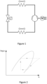
- Commercial systems are so-called single stage heat pumps, see Figure 1 . Between the evaporator and the condenser there is one stage (one compressor and one expansion valve).
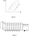
- Figure 2 shows a theoretical plot of log p versus h, where p is the pressure and h is the enthalpy, for a single stage heat pump cycle with a dome-like region, the so-called liquid-vapour dome, and the cycle for a single stage heat pump: the lower horizontal line with an arrow pointing to the right representing the evaporation step, followed by compression step, a condensation step (upper horizontal line with arrow pointing to the left) and finally expansion at constant enthalpy (vertical line with arrow pointing downwards).
- the so-called liquid-vapour dome At lower enthalpies than those within the dome-like region (the so-called liquid-vapour dome) (i.e.
- liquid exists with a mix of saturated liquid and saturated vapour in the dome-like region and vapour existing at higher enthalpies than those within the dome region (i.e. to the right thereof).
- the critical point is at the apex of the dome region with vapour existing to the non-dome-like area to the left thereof, a vapour existing in the non-dome-like area to the right thereof and a supercritical fluid existing above the critical point.
- two stage heat pumps can be used comprising an additional intermediate pressure level, two compressors and two expansion valves.
- the advantage of two stages is that the pressure ratio which has to be realised by each of the compressors is halved compared with that for a single stage system.
- gas compressed in the first stage can be cooled, whereupon the density increases and the temperature of the gas at the second stage decreases. The performance of the second compression step can then be improved.
- FIG. 3 shows a theoretical plot of log p versus h, where p is the pressure and h is the enthalpy, for a two stage heat pump cycle with the same liquid-vapour dome as for Figure 2 .
- Three stage systems are known for cryogenic applications. The greater the number of stages the higher will be the performance of a heat pump, but with the disadvantage that the investment required increases considerably.
- GB 2049901A discloses a heat pump apparatus, comprising: a plurality of separate heat pump circuits, each of the said circuits being adapted to have a heat transferring fluid circulate therethrough and each including respective evaporator means and condenser means, and means for directing a mass flow to be heated into heat exchange relationship with each of the said condenser means in series, whereby the temperature of the mass flow to be heated rises when in heat exchange relationship with the fluids circulating through the condenser means of the respective heat pump circuits.
- An advantage of embodiments of the present invention is that the compression of the medium proceeds in different steps increasing the theoretical efficiency of the compression.
- Another advantage of embodiments of the present invention is that after each compressor step the liquid medium is cooled by evaporating a small fraction thereof and admixing the vapour thereby produced after expansion in the respective step. As a result the liquid medium has a higher density due to more mass per unit volume being compressed and a greater mass is transported.
- the compression step places the compressed fluid vapour in a superheated state. The cooling of this superheated vapour by the admixture with evaporated fluid fed back from a higher stage brings the fluid back to a non-superheated or saturated state or a state close thereto.
- the multistage heat pump of embodiments of the present invention is controlled in such a way that at least one of the stages is operated close to saturation. Preferably all the stages where there is compression and some expansion of fluid returned from a higher pressure tank are operated close to saturation.
- a further advantage of embodiments of the present invention is that in each stage where there is an intermediate expansion of a portion of the fluid fed back from a higher stage the vapour formed is not only close to saturation but is immediately extracted and compressed back under high pressure to the next stage (finally to the highest pressure i.e. the condenser pressure). As a result this gas does not need to be compressed from the lowest pressure (evaporator pressure) to the highest pressure (condenser pressure).
- the use of smaller compression ratios in the stages means that each compressor operates more efficiently.
- a still further advantage of embodiments of the present invention is that upon cooling a liquid medium heat can be exchanged in steps, whereby the temperature difference between cooling medium and the medium to be cooled is more or less constant.
- the same reasoning is also applicable to the heating of the liquid medium.
- cooling can be delivered to different cooling consumers at different temperatures. Cooling at the lowest temperature is delivered by Tx, cooling at a higher temperature is delivered by the fluid in the appropriate tank. The same reasoning is also applicable to the heating of different consumers at different temperatures.
- a still further advantage of the present invention is that a rough calculation of the COP (Coefficient of Performance, being the ratio of the thermal power delivered (i.e. the heat produced) and the required compressor power (i.e. the electricity consumption of the compressor) in multi-stage systems can be double that of a single stage system.
- a multi-stage system would thus consume half the energy of a single stage system.
- the same reasoning applies to cooling installations with compressors in that the working principles for a compressor cooling installation are the same as those for a heat engine such as a multistage heat pump or in an analogous way a multistage Rankine cycle generator, or a combination of heating and cooling methods and installations. If there is a demand for cooling and heating both the cooling energy and the heating energy of the multi stage heat pump can be used.
- a cooling installation is also a heat pump.
- a still further advantage of embodiments of the present invention is an increase the efficiency of the compression of the vapour.
- a first aspect of embodiments of the present invention is the provision of a multi-stage heat engine such as a multistage heat pump (e.g. a heating installation or a cooling installation or a combination of a heating and cooling installation) or in an analogous way a multistage Rankine cycle generator comprising an evaporator and a condenser; an expander section including more than two expander stages; a compressor section comprising more than two vapour compression stages that co-operate with the expander section; x tanks wherein x is at least three (e.g. T1 to Tx) for holding gaseous phases (e.g. G1 to Gx) and liquid phases (e.g.
- a multistage heat pump e.g. a heating installation or a cooling installation or a combination of a heating and cooling installation
- a multistage Rankine cycle generator comprising an evaporator and a condenser
- an expander section including more than two expander stages
- a compressor section comprising more than two vapour compression
- the expander section having x-1 expansion valves (e.g. V1 to Vx-1), the compressor section being adapted to compress the gaseous phase in each tank and to pass to an adjacent tank with a higher pressure to that in which expansion had occurred and move the compressed fluid to the next adjacent tank at a higher pressure, the expander section being adapted to expand a part of the compressed fluid (liquid) in each tank, through the expansion valve (V) of that tank, to expand the fluid in the adjacent tank at a lower pressure, the compressor and expander sections being adapted to output the gaseous phase at the highest pressure to the condenser and the liquid phase at the lowest pressure to the evaporator, the output of the condenser being fed back to tank (T1) at the highest pressure and the output of the evaporator being fed back to the tank (Tx) at the lowest pressure.
- x-1 expansion valves e.g. V1 to Vx-1
- said multi-stage heat engine such as a multistage heat pump (e.g. a heating installation or a cooling installation or a combination of a heating and cooling installation) or in an analogous way a multistage Rankine cycle generator constitutes multiple evaporator-compressor-condenser-expander modules which are substantially identical to one another.
- the multistage heat engine such as a multistage heat pump (e.g. a heating installation or a cooling installation or a combination of a heating and cooling installation)or in an analogous way a multistage Rankine can comprise three of more tanks which are integrated into a whole rather than being a collection of separate heat engine circuits such as multistage heat pump circuits ((e.g.
- a heating circuits or a cooling circuits or a combination of a heating and cooling circuits or in an analogous way a multistage Rankine cycle generator circuits.
- a multistage heat engine circuit such as a multistage heat pump (e.g. a heating installation or a cooling installation or a combination of a heating and cooling installation) or in an analogous way a multistage Rankine cycle generator circuit which comprises sub-circuits.
- a further aspect of embodiments of the present invention is that the compression of vapour in at least one tank places the compressed vapour in a superheated state and the expansion of the fluid from an adjacent tank, which is at a higher pressure, in the at least one tank at a lower pressure brings the vapour in this latter tank at a saturated or close to saturated state.
- the cooling effect of this expansion keeps the vapour in that tank at or close to saturated.
- the liquid/vapour stage can be within the liquid vapour dome.
- a further aspect of embodiments of the present invention is to bring the vapour at the suction side of each compressor to a saturated or close to saturated state, because this will increase the efficiency of the compression of the vapour.
- a second aspect of embodiments of the present invention is the provision of a process for increasing the temperature of a medium, said process comprising the steps of: subjecting said medium to multiple evaporation-compression-condensation-expansion-cycles in a multi-stage heat engine such as a multistage heat pump (e.g. a heating installation or a cooling installation or a combination of a heating and cooling installation) or in an analogous way a multistage Rankine cycle generator according to the first aspect of the present invention.
- a multi-stage heat engine such as a multistage heat pump (e.g. a heating installation or a cooling installation or a combination of a heating and cooling installation) or in an analogous way a multistage Rankine cycle generator according to the first aspect of the present invention.
- embodiments of the present invention provide process for increasing or decreasing the temperature of a medium, in a multi-stage heat engine comprising an evaporator and a condenser; an expander section including more than two expander stages; a compressor section comprising more than two vapour compression stages that co-operate with the expander section; x tanks wherein x is at least three (e.g. T1 to Tx) for holding gaseous phases (e.g. G1 to Gx) and liquid phases (e.g. L1 to Lx) of a fluid; the expander section having x-1 expansion valves (e.g.
- V1 to Vx-1 the method comprising: compressing the gaseous phase in a first tank to a higher pressure and moving the compressed fluid to a second next adjacent tank at a higher pressure, the expander section being adapted to expand a part of the compressed fluid (liquid) in the second next adjacent tank, through the expansion valve (V) of that tank, to expand the fluid in the first tank at a lower pressure, the compressor and expander sections being adapted to output the gaseous phase at the highest pressure to the condenser and the liquid phase at the lowest pressure to the evaporator, the output of the condenser being fed back to tank (T1) at the highest pressure and the output of the evaporator being fed back to the tank (Tx) at the lowest pressure.
- the compression of vapour in at least one tank places the compressed vapour in a superheated state.
- Each tank has pressure, and/or temperature and/or liquid level sensors and controllable expansion values; the method comprising regulating the controllable valves in accordance with the outputs of at least one of the sensors to maintain a level of liquid in each tank and maintain the vapour of each tank in a saturated state or close thereto.
- the method can include driving a group of or all compressors axially by a single motor.
- the method can include providing a direct connection between the pressure vessel and the pressure step in the compressor for each stage of the multiple-stage heat engine.
- the method may include heating or cooling a liquid medium, whereby heat can be exchanged in steps, whereby the temperature difference between cooling or heating medium and the medium to be cooled or heated is more or less constant.
- the method may include delivering cooling energy or heating energy is delivered to different consumers at different temperatures.
- a further aspect of the method is to bring the vapour at the suction side of each compressor to a saturated or close to saturated state, because this will increase the efficiency of the compression of the vapour.
- first second, third and the like in the description and in the claims are used for distinguishing between similar elements and not necessarily for describing a sequence, either temporally, spatially, in ranking or in any other manner. It is to be understood that the terms so used are interchangeable under appropriate circumstances and that the embodiments of the invention described herein are capable of operation in other sequences than described or illustrated herein.
- a heat pump as used in disclosing the present invention, is a device which transfers heat (hot or cold energy) from a cooler reservoir to a hotter one (or vice versa), expending mechanical energy in the process.
- the main purpose can be to heat the hot reservoir or to refrigerate the cold one.
- Both heating and cooling methods or installations and a combination of heating or cooling methods and installations are included within the scope of the present invention.
- a multi stage heat pump can be used for cooling a cooler reservoir (heat is than wasted in the environment).
- An integrated multi-stage heat pump as disclosed as embodiments of the present invention, is a heat pump with multiple evaporation-compression-condensation-expansion cycle modules thereby providing an easily expandable compact heat pump.
- Such an installation may have one evaporator and one condenser but multiple compressors and expansion valves.
- the compressors for the stage or stages at high pressure can be smaller than the compressors for the stage or stages at lower pressure as the density of the vapour is lower at high pressure.
- a compressor as used in disclosing the present invention, is a machine for increasing the pressure of a gas or vapour.
- a condenser as used in disclosing the present invention, is a heat-transfer device that reduces a thermodynamic fluid from its vapour phase to its liquid phase, such as in a vapour-compression refrigeration plant or in a condensing steam power plant.
- An evaporator as used in disclosing the present invention, is any of many devices in which liquid is changed to the vapour state by the addition of heat, for example, distiller, still, dryer, water purifier, or refrigeration system element where evaporation proceeds at low pressure and consequent low temperature.
- An expansion system is a gas-liquid recovery system in which a cooling effect is obtained by rapidly depressurizing a liquid fraction.
- Ground as used in disclosing the present invention, embraces everything solid or molten below the earth's surface.
- the integral multi-stage heat pump a multistage heat pump for heating or cooling or a combination of a heating and cooling
- the integral multi-stage heat pump comprises an evaporator and a condenser; an expander section including more than two expander stages; a compressor section comprising more than two vapour compression stages that co-operate with the expander section; at least three tanks (e.g. T1 to T10 but more or less can be used) for holding gaseous phases (e.g. G1 to G10 but more or less can be used) and liquid phases (e.g. L1 to L10 but more or less can be used) of a fluid; the expander section having expansion valves (e.g.
- the compressor section being adapted to compress the gaseous phase (Gx+1) in each tank (Tx+1 with x being an integer between 1 and 9 but more or less can be used) and move the compressed fluid to the adjacent tank (Tx) at a higher pressure
- the expander section being adapted to expand a part of the compressed fluid (liquid Ly) in each tank (Ty with y being an integer between 1 and 9 but more or less can be used), through the expansion valve (Vy) of that tank, to expand the fluid in the adjacent tank (Ty +1) at a lower pressure
- the compressor and expander sections being adapted to output the gaseous phase at the highest pressure to the condenser and the liquid phase at the lowest pressure to the evaporator, the output of the condenser being fed back to tank (T 1) at the highest pressure and the output of the evaporator being fed back to the tank (T10) at the lowest pressure.
- a further aspect of embodiments of the present invention is that the compression of vapour in at least one tank places the compressed vapour in a superheated state and the expansion of the fluid in the adjacent tank at a lower pressure brings the vapour in this latter tank at a saturated or close to saturated state.
- the cooling effect of this expansion keeps the vapour in that tank at or close to saturated.
- each tank includes pressure, temperature and/or liquid level sensors and controllable expansion values.
- a controller is provided adapted to regulate the controllable valves in accordance with the outputs of the sensors to maintain a level of liquid in each tank and maintain the vapour of each tank in a saturated state or close thereto.
- a further aspect of embodiments of the present invention is to bring the vapour at the suction side of each compressor to a saturated or close to saturated state, because this will increase the efficiency of the compression of the vapour.
- the compressor section comprises a number of compressors driven axially by a single motor. All or some of the compressors can be driven by one motor and an axial shaft. The compressors are not necessarily driven by an axial shaft.
- FIG. 4 is a schematic of an eight stage heat pump system comprising pressure vessels (tanks T1 to T9 for holding gaseous phases G1 to G9 and liquid phases L1 to L9), compressors driven axially by a single motor, expansion systems (expansion valves V1 to V7), a condenser, an evaporator integrated into a single installation according to the present invention.
- pressure vessels tanks T1 to T9 for holding gaseous phases G1 to G9 and liquid phases L1 to L9
- expansion systems expansion valves V1 to V7
- condenser an evaporator integrated into a single installation according to the present invention.
- the investment costs are considerably reduced compared with the classic arrangement with separate pressure vessels, compressors and expansion systems.
- the number of stages, and hence the temperature lift (or sink for cooling) is easily extendable.
- the different compression steps are here simply depicted by axially driven fans, although different systems are possible.
- a direct connection is provided between the pressure vessel and the pressure step in the compressor for each stage of the multiple-stage heat pump.
- the multiple-stage heat pump is integrated.
- Figure 5 is a theoretical plot of log p versus h, where p is the pressure and h is the enthalpy, for an eight stage heat pump cycle with the same liquid-vapour dome as for Figures 2 and 3 .
- the greater the number of stages provided the closer the compression proceeds in the co-existence region (on the gas side) and the closer the expansion proceeds in the co-existence region (on the liquid side).
- FIG. 6 is a schematic overview of a ten stage heat pump system, according to the present invention, with tanks T1 to T10 for holding gaseous phases G1 to G10 and liquid phases L1 to L10 of a fluid and expansion valves V1 to V9, a condenser, an evaporator and with the compressors driven axially by a single motor (although more motors may be used, e.g. groups of compressors may each be driven by one motor. It comprises condenser on the left side and an evaporator on the right side. The condenser is fed with gaseous phase of the system fluid such as ammonia at high pressure whereas the evaporator is fed with the liquid phase from a pump.
- a single motor although more motors may be used, e.g. groups of compressors may each be driven by one motor.
- the condenser is fed with gaseous phase of the system fluid such as ammonia at high pressure whereas the evaporator is fed with the liquid phase from a pump.
- a third aspect of the present invention is the provision of the use of multi-stage heat pumps, (e.g. multistage heat pump for heating or cooling or a combination of a heating and cooling), according to the first aspect of the present invention, in the extraction of heat (hot or cold energy) from renewable energy sources, residual heat and wastewater.
- multi-stage heat pumps e.g. multistage heat pump for heating or cooling or a combination of a heating and cooling
- a fourth aspect of the present invention is the provision of the use of multi-stage heat pumps (e.g. a multistage heat pump for heating or cooling or a combination of a heating and cooling), according to the first aspect of the present invention, in the extraction of heat (e.g. hot or cold energy) from wastewater or other residual heat.
- multi-stage heat pumps e.g. a multistage heat pump for heating or cooling or a combination of a heating and cooling
- the renewable energy sources are selected from the group consisting of ambient air, freshwater, seawater, groundwater and the ground.
- the multi-stage heat pump (e.g. a multistage heat pump for heating or cooling or a combination of a heating and cooling), according to embodiments of the present invention, is regarded as being an integral part of installations for the extraction of heat (e.g. hot or cold energy) from renewable energy sources e.g. in solar boilers and from the ambient air, groundwater and ground in horizontal or vertical ground source heat pumps (GSHP).
- the heat from the ground can either be provided by fairly shallow boreholes or very deep boreholes tapping into geothermal heat sources.
- the heat e.g. hot or cold energy
- the heat available in the air, freshwater, seawater, groundwater and the ground is transformed to heat (e.g. cold or hot energy) at a usable temperature.
- the electricity consumption is substantially reduced over that required for single stage heat pumps which increases the efficiency with which energy can be extracted from renewable energy sources or other heat sources.
- Heat pumps e.g. a multistage heat pump for heating or cooling or a combination of a heating and cooling
- heat pumps e.g.
- a multistage heat pump for heating or cooling or a combination of a heating and cooling can also be utilised to lift or sink the temperature of low grade waste heat (hot energy or cold energy) to usable temperature levels.
- Part of the waste heat (hot or cold energy) which is now disposed of can be used in the process or for the provision of central heating (or cooling) were the temperature thereof to have been higher (or lower) whereby a heat pump (e.g. a multistage heat pump for heating or cooling or a combination of a heating and cooling), according to embodiments of the present invention can be used.
- a heat pump e.g. a multistage heat pump for heating or cooling or a combination of a heating and cooling
- Embodiments of the present invention which provide an integrated multi-stage system expand the application possibilities and energy savings.
- the heat pumps can be used in cooling applications e.g. industrial, commercial, HVAC and air-conditioning.
- cooling applications e.g. industrial, commercial, HVAC and air-conditioning.
- multi-stage cooling systems the electricity consumption can be reduced over that with the classical single stage cooling systems.
- heat pumps can be used for both heating and cooling applications e.g. cooling part of the office with sun radiation and heating part off the office without sun radiation.
- Analogous to multistage heat pumps the present invention also includes multistage Rankine cycle engines.
- the use of multiple cycles can also here result in a higher efficiency. With the same amount of rest or geothermal heat thus more electricity can be generated.
Landscapes
- Engineering & Computer Science (AREA)
- Physics & Mathematics (AREA)
- Mechanical Engineering (AREA)
- Thermal Sciences (AREA)
- General Engineering & Computer Science (AREA)
- Chemical & Material Sciences (AREA)
- Analytical Chemistry (AREA)
- Power Engineering (AREA)
- Engine Equipment That Uses Special Cycles (AREA)
Claims (14)
- Mehrstufige Wärmekraftmaschine, umfassend: einen Verdampfer und einen Kondensator;ein Expansionsabschnitt mit mehr als zwei Expansionsstufen;einen Verdichterabschnitt, umfassend mehr als zwei Dampfverdichtungsstufen, die mit dem Expansionsabschnitt zusammenwirken;x Tanks, wobei x mindestens drei ist (z. B. T1 bis Tx) zum Aufnehmen von Gasphasen (z. B. G1 bis Gx) und Flüssigphasen (z. B. L1 bis Lx) eines Fluids;wobei der Expansionsabschnitt x-1 Expansionsventile (z. B. V1 bis Vx-1) aufweist, wobei der Verdichterabschnitt so angepasst ist, dass er die Gasphase aus einem ersten Tank auf einen höheren Druck komprimiert und das komprimierte Fluid zu einem zweiten, nächstbenachbarten Tank mit einem höheren Druck bewegt, wobei der Expansionsabschnitt so angepasst ist, dass er einen Teil des komprimierten Fluids (Flüssigkeit) aus dem zweiten, nächstbenachbarten Tank durch das Expansionsventil (V) dieses Tanks bewegt, um das Fluid in dem ersten Tank bei einem niedrigeren Druck zu expandieren, wobei die Verdichter- und Expansionsabschnitte so beschaffen sind, dass sie die Gasphase mit dem höchsten Druck an den Kondensator und die Flüssigphase mit dem niedrigsten Druck an den Verdampfer abgeben, wobei der Ausgang des Kondensators mit dem höchsten Druck in den Tank (T1) zurückgeführt wird und der Ausgang des Verdampfers mit dem niedrigsten Druck in den Tank (Tx) zurückgeführt wird,dadurch gekennzeichnet, dass die Ausdehnung des Fluids im ersten Behälter bei einem niedrigeren Druck den Dampf in diesem letzteren Behälter in einen gesättigten oder nahezu gesättigten Zustand bringt,dadurch, dass die mehrstufige Wärmekraftmaschine so angepasst ist, dass in jeder Verdichtungsstufe, in der eine aus einem Behälter mit höherem Druck zurückgeführte Flüssigkeit expandiert wird, die Kühlwirkung dieser Expansion den Dampf in diesem Behälter gesättigt oder nahezu gesättigt hält,und dass jeder Tank Druck- und/oder Temperatur- und/oder Flüssigkeitsstandsensoren und steuerbare Expansionswerte aufweist; wobei die Wärmekraftmaschine ferner eine Steuerung umfasst, die so angepasst ist, dass sie die steuerbaren Ventile in Übereinstimmung mit den Ausgangssignalen von mindestens einem der Sensoren steuert, um einen Flüssigkeitsstand in jedem Tank aufrechtzuerhalten und den Dampf jedes Tanks im gesättigten Zustand oder nahe daran zu halten.
- Mehrstufige Wärmekraftmaschine nach Anspruch 1, wobei der Dampf an der Saugseite jedes Verdichters in einen gesättigten oder nahezu gesättigten Zustand gebracht wird.
- Mehrstufige Wärmekraftmaschine nach Anspruch 1, die so angepasst ist, dass die Verdichtung des Dampfes aus dem ersten Tank den verdichteten Dampf in einen überhitzten Zustand versetzt.
- Mehrstufige Wärmekraftmaschine nach einem der vorstehenden Ansprüche, wobei der Verdichterabschnitt eine Gruppe von oder alle Verdichter umfasst, die von einem einzelnen Motor axial angetrieben werden.
- Mehrstufige Wärmekraftmaschine nach einem der vorstehenden Ansprüche, wobei für jede Stufe der mehrstufigen Wärmekraftmaschine eine direkte Verbindung zwischen dem Druckbehälter und der Druckstufe im Verdichter vorgesehen ist.
- Mehrstufige Wärmekraftmaschine nach einem der vorstehenden Ansprüche, wobei die mehrstufige Wärmekraftmaschine integriert ist.
- Mehrstufige Wärmekraftmaschine nach einem der vorstehenden Ansprüche, wobei die mehrstufige Wärmekraftmaschine eine mehrstufige Wärmepumpe oder in analoger Weise ein mehrstufiger Rankine-Prozess-Motor ist.
- Mehrstufige Wärmekraftmaschine nach einem der vorstehenden Ansprüche, die so angepasst ist, dass beim Erwärmen oder Kühlen eines flüssigen Mediums ein stufenweiser Wärmeaustausch erfolgen kann, wobei die Temperaturdifferenz zwischen Kühl- oder Heizmedium und dem zu kühlenden oder zu erwärmenden Medium mehr oder weniger konstant ist.
- Mehrstufige Wärmekraftmaschine nach einem der vorstehenden Ansprüche, die so angepasst ist, dass Kälteenergie oder Heizenergie an verschiedene Verbraucher mit unterschiedlichen Temperaturen geliefert wird.
- Verfahren zum Erhöhen oder Senken der Temperatur eines Mediums, wobei das Verfahren die folgenden Schritte umfasst: Unterziehen des Mediums mehreren Verdampfungs-Verdichtungs-Kondensations-Expansions-Zyklen in einer mehrstufigen Wärmekraftmaschine nach einem der Ansprüche 1 bis 9.
- Verwenden von mehrstufigen Wärmekraftmaschinen nach einem der Ansprüche 1 bis 9 zum Umwandeln von Wärmeenergie aus erneuerbaren Energiequellen auf höhere oder niedrigere Temperaturen.
- Verwenden nach Anspruch 11, wobei die erneuerbaren Energiequellen aus der Gruppe ausgewählt sind bestehend aus Umgebungsluft, Süßwasser, Meerwasser, Grundwasser und dem Boden.
- Verwenden von mehrstufigen Wärmekraftmaschinen nach einem der Ansprüche 1 bis 9 zum Umwandeln von Wärme aus Restwärme oder Abwasser auf höhere oder niedrigere Temperaturen.
- Verfahren zum Betreiben einer mehrstufigen Wärmekraftmaschine, wobei die mehrstufige Wärmekraftmaschine aufweist:einen Verdampfer und einen Kondensator;ein Expansionsabschnitt mit mehr als zwei Expansionsstufen;einen Verdichterabschnitt, umfassend mehr als zwei Dampfverdichtungsstufen, die mit dem Expansionsabschnitt zusammenwirken;x Tanks, wobei x mindestens drei ist (z. B. T1 bis Tx) zum Aufnehmen von Gasphasen (z. B. G1 bis Gx) und Flüssigphasen (z. B. L1 bis Lx) eines Fluids;wobei der Expansionsabschnitt x-1 Expansionsventile (z. B. V1 bis Vx-1) aufweist, wobei das Verfahren umfasst: der Verdichterabschnitt komprimiert die Gasphase aus einem ersten Tank auf einen höheren Druck und bewegt das komprimierte Fluid zu einem zweiten, nächstbenachbarten Tank mit einem höheren Druck, der Expansionsabschnitt bewegt einen Teil des komprimierten Fluids (Flüssigkeit) aus dem zweiten, nächstbenachbarten Tank durch das Expansionsventil (V) dieses Tanks und expandiert das Fluid im ersten Tank mit einem niedrigeren Druck, die Verdichter- und Expansionsabschnitte die Gasphase mit dem höchsten Druck an den Kondensator und die Flüssigphase mit dem niedrigsten Druck an den Verdampfer abgeben, wobei der Ausgang des Kondensators mit dem höchsten Druck in den Tank (T1) und der Ausgang des Verdampfers mit dem niedrigsten Druck in den Tank (Tx) zurückgeführt wird,dadurch gekennzeichnet, dass die Ausdehnung des Fluids im ersten Behälter bei einem niedrigeren Druck den Dampf in diesem letzteren Behälter in einen gesättigten oder nahezu gesättigten Zustand bringt,dadurch, dass die mehrstufige Wärmekraftmaschine so angepasst ist, dass in jeder Verdichtungsstufe, in der eine aus einem Behälter mit höherem Druck zurückgeführte Flüssigkeit expandiert wird, die Kühlwirkung dieser Expansion den Dampf in diesem Behälter gesättigt oder nahezu gesättigt hält,und dass jeder Tank Druck- und/oder Temperatur- und/oder Flüssigkeitsstandsensoren und steuerbare Expansionswerte aufweist; wobei das Verfahren ferner das Steuern der steuerbaren Ventile in Übereinstimmung mit den Ausgaben von mindestens einem der Sensoren umfasst, um einen Flüssigkeitsstand in jedem Tank aufrechtzuerhalten und den Dampf jedes Tanks im gesättigten Zustand oder nahe daran zu halten.
Applications Claiming Priority (2)
| Application Number | Priority Date | Filing Date | Title |
|---|---|---|---|
| EP14169727.6A EP2947401A1 (de) | 2014-05-23 | 2014-05-23 | Mehrstufige Wärmekraftmaschine |
| PCT/EP2015/061431 WO2015177352A1 (en) | 2014-05-23 | 2015-05-22 | Multi-stage heat engine |
Publications (3)
| Publication Number | Publication Date |
|---|---|
| EP3146276A1 EP3146276A1 (de) | 2017-03-29 |
| EP3146276C0 EP3146276C0 (de) | 2023-08-23 |
| EP3146276B1 true EP3146276B1 (de) | 2023-08-23 |
Family
ID=50884218
Family Applications (2)
| Application Number | Title | Priority Date | Filing Date |
|---|---|---|---|
| EP14169727.6A Withdrawn EP2947401A1 (de) | 2014-05-23 | 2014-05-23 | Mehrstufige Wärmekraftmaschine |
| EP15727590.0A Active EP3146276B1 (de) | 2014-05-23 | 2015-05-22 | Mehrstufige waermekraftmaschine |
Family Applications Before (1)
| Application Number | Title | Priority Date | Filing Date |
|---|---|---|---|
| EP14169727.6A Withdrawn EP2947401A1 (de) | 2014-05-23 | 2014-05-23 | Mehrstufige Wärmekraftmaschine |
Country Status (5)
| Country | Link |
|---|---|
| US (1) | US10712050B2 (de) |
| EP (2) | EP2947401A1 (de) |
| CN (1) | CN106662370A (de) |
| MX (1) | MX2016015306A (de) |
| WO (1) | WO2015177352A1 (de) |
Families Citing this family (2)
| Publication number | Priority date | Publication date | Assignee | Title |
|---|---|---|---|---|
| CN112327975B (zh) * | 2020-11-03 | 2022-06-17 | 张勇 | 一种高效多级烘干系统的控制方法 |
| DE102021214258A1 (de) | 2021-12-13 | 2023-06-15 | Volkswagen Aktiengesellschaft | Wärmepumpenkaskade und Verfahren zur Erwärmung oder Abkühlung eines Kühlmittels mittels einer Wärmepumpenkaskade |
Family Cites Families (8)
| Publication number | Priority date | Publication date | Assignee | Title |
|---|---|---|---|---|
| FI791079A7 (fi) | 1979-04-02 | 1981-01-01 | Valmet Oy | Lämpöpumpun hyväksikäyttöön perustuva menetelmä lämmön talteenotossa. |
| US4457768A (en) * | 1982-12-13 | 1984-07-03 | Phillips Petroleum Company | Control of a refrigeration process |
| KR20080001263A (ko) * | 2006-06-29 | 2008-01-03 | 엘지.필립스 엘시디 주식회사 | 듀얼 플레이트 유기 전계 발광 소자 및 이의 제조 방법 |
| KR20080012638A (ko) * | 2006-08-04 | 2008-02-12 | 삼성전자주식회사 | 냉동시스템 |
| CN200940968Y (zh) * | 2006-08-07 | 2007-08-29 | 北京市京科伦冷冻设备有限公司 | 一种制冷机组结构 |
| CN101688528A (zh) * | 2007-05-07 | 2010-03-31 | 开利公司 | 电动机-压缩机驱动装置 |
| WO2011049778A1 (en) * | 2009-10-23 | 2011-04-28 | Carrier Corporation | Parameter control in transport refrigeration system and methods for same |
| JP2014119157A (ja) * | 2012-12-14 | 2014-06-30 | Sharp Corp | ヒートポンプ式加熱装置 |
-
2014
- 2014-05-23 EP EP14169727.6A patent/EP2947401A1/de not_active Withdrawn
-
2015
- 2015-05-22 MX MX2016015306A patent/MX2016015306A/es unknown
- 2015-05-22 WO PCT/EP2015/061431 patent/WO2015177352A1/en not_active Ceased
- 2015-05-22 EP EP15727590.0A patent/EP3146276B1/de active Active
- 2015-05-22 US US15/312,555 patent/US10712050B2/en active Active
- 2015-05-22 CN CN201580026698.7A patent/CN106662370A/zh active Pending
Also Published As
| Publication number | Publication date |
|---|---|
| MX2016015306A (es) | 2017-05-04 |
| CN106662370A (zh) | 2017-05-10 |
| US20170089612A1 (en) | 2017-03-30 |
| WO2015177352A1 (en) | 2015-11-26 |
| EP3146276C0 (de) | 2023-08-23 |
| EP2947401A1 (de) | 2015-11-25 |
| US10712050B2 (en) | 2020-07-14 |
| EP3146276A1 (de) | 2017-03-29 |
Similar Documents
| Publication | Publication Date | Title |
|---|---|---|
| EP2021587B1 (de) | Verfahren und system zur erzeugung von elektrizität aus einer wärmequelle | |
| US4474018A (en) | Heat pump system for production of domestic hot water | |
| Asim et al. | Thermodynamic and thermo-economic analysis of integrated organic Rankine cycle for waste heat recovery from vapor compression refrigeration cycle | |
| EP3303779B1 (de) | Wärmekraftmaschinen, systeme für unter druck stehendes kältemittel und zugehörige verfahren | |
| US20090266075A1 (en) | Process and device for using of low temperature heat for the production of electrical energy | |
| WO2019114536A1 (zh) | 构造冷源能量回收系统、热力发动机系统及能量回收方法 | |
| JP6679728B2 (ja) | 熱源からの廃熱を機械的エネルギーに変換する有機ランキンサイクルおよびかかる有機ランキンサイクルを利用する圧縮機設備 | |
| Li et al. | Entransy dissipation/loss-based optimization of two-stage organic Rankine cycle (TSORC) with R245fa for geothermal power generation | |
| US9869495B2 (en) | Multi-cycle power generator | |
| JP2022513231A (ja) | ヒートポンプ装置およびヒートポンプ装置を備える地域熱供給網 | |
| US10712050B2 (en) | Multi-stage heat engine | |
| RU2722436C2 (ru) | Каскадный цикл и способ регенерации отходящего тепла | |
| KR101315918B1 (ko) | 저온 폐열 및 흡수식 냉동기를 이용한 orc 열병합 시스템 | |
| US10060299B2 (en) | Thermo-elevation plant and method | |
| RU2306496C1 (ru) | Двухступенчатая теплонасосная установка | |
| RU2181864C1 (ru) | Способ охлаждения рабочего тела и устройство для его осуществления | |
| RU2606847C1 (ru) | Способ преобразования низкопотенциальной тепловой энергии | |
| UA124256C2 (uk) | Когенераційна установка | |
| JADHAO et al. | An industrial heat pump for steam and fuel Savings | |
| Dobrovicescu et al. | EXERGY ANALYSIS OF A VAPOUR COMPRESSION HEAT PUMP | |
| Yanturin et al. | APPLICATION OF ABSORPTION MACHINES IN TRIGENERATION CYCLES | |
| Filipan et al. | Influence of condensing temperature on heat pump efficiency | |
| WO2017157924A2 (en) | Heat pump apparatus | |
| CZ306780B6 (cs) | Tepelný stroj | |
| JP2016001098A (ja) | 複合空調装置 |
Legal Events
| Date | Code | Title | Description |
|---|---|---|---|
| STAA | Information on the status of an ep patent application or granted ep patent |
Free format text: STATUS: THE INTERNATIONAL PUBLICATION HAS BEEN MADE |
|
| PUAI | Public reference made under article 153(3) epc to a published international application that has entered the european phase |
Free format text: ORIGINAL CODE: 0009012 |
|
| STAA | Information on the status of an ep patent application or granted ep patent |
Free format text: STATUS: REQUEST FOR EXAMINATION WAS MADE |
|
| 17P | Request for examination filed |
Effective date: 20161123 |
|
| AK | Designated contracting states |
Kind code of ref document: A1 Designated state(s): AL AT BE BG CH CY CZ DE DK EE ES FI FR GB GR HR HU IE IS IT LI LT LU LV MC MK MT NL NO PL PT RO RS SE SI SK SM TR |
|
| AX | Request for extension of the european patent |
Extension state: BA ME |
|
| DAV | Request for validation of the european patent (deleted) | ||
| DAX | Request for extension of the european patent (deleted) | ||
| REG | Reference to a national code |
Ref country code: HK Ref legal event code: DE Ref document number: 1232587 Country of ref document: HK |
|
| STAA | Information on the status of an ep patent application or granted ep patent |
Free format text: STATUS: EXAMINATION IS IN PROGRESS |
|
| 17Q | First examination report despatched |
Effective date: 20200422 |
|
| GRAP | Despatch of communication of intention to grant a patent |
Free format text: ORIGINAL CODE: EPIDOSNIGR1 |
|
| STAA | Information on the status of an ep patent application or granted ep patent |
Free format text: STATUS: GRANT OF PATENT IS INTENDED |
|
| INTG | Intention to grant announced |
Effective date: 20220601 |
|
| GRAJ | Information related to disapproval of communication of intention to grant by the applicant or resumption of examination proceedings by the epo deleted |
Free format text: ORIGINAL CODE: EPIDOSDIGR1 |
|
| STAA | Information on the status of an ep patent application or granted ep patent |
Free format text: STATUS: EXAMINATION IS IN PROGRESS |
|
| INTC | Intention to grant announced (deleted) | ||
| GRAP | Despatch of communication of intention to grant a patent |
Free format text: ORIGINAL CODE: EPIDOSNIGR1 |
|
| STAA | Information on the status of an ep patent application or granted ep patent |
Free format text: STATUS: GRANT OF PATENT IS INTENDED |
|
| INTG | Intention to grant announced |
Effective date: 20230306 |
|
| P01 | Opt-out of the competence of the unified patent court (upc) registered |
Effective date: 20230528 |
|
| GRAS | Grant fee paid |
Free format text: ORIGINAL CODE: EPIDOSNIGR3 |
|
| GRAA | (expected) grant |
Free format text: ORIGINAL CODE: 0009210 |
|
| STAA | Information on the status of an ep patent application or granted ep patent |
Free format text: STATUS: THE PATENT HAS BEEN GRANTED |
|
| AK | Designated contracting states |
Kind code of ref document: B1 Designated state(s): AL AT BE BG CH CY CZ DE DK EE ES FI FR GB GR HR HU IE IS IT LI LT LU LV MC MK MT NL NO PL PT RO RS SE SI SK SM TR |
|
| REG | Reference to a national code |
Ref country code: GB Ref legal event code: FG4D |
|
| REG | Reference to a national code |
Ref country code: CH Ref legal event code: EP |
|
| REG | Reference to a national code |
Ref country code: DE Ref legal event code: R096 Ref document number: 602015085262 Country of ref document: DE |
|
| REG | Reference to a national code |
Ref country code: IE Ref legal event code: FG4D |
|
| P04 | Withdrawal of opt-out of the competence of the unified patent court (upc) registered |
Effective date: 20230925 |
|
| U01 | Request for unitary effect filed |
Effective date: 20230921 |
|
| U07 | Unitary effect registered |
Designated state(s): AT BE BG DE DK EE FI FR IT LT LU LV MT NL PT SE SI Effective date: 20230928 |
|
| REG | Reference to a national code |
Ref country code: HK Ref legal event code: WD Ref document number: 1232587 Country of ref document: HK |
|
| PG25 | Lapsed in a contracting state [announced via postgrant information from national office to epo] |
Ref country code: GR Free format text: LAPSE BECAUSE OF FAILURE TO SUBMIT A TRANSLATION OF THE DESCRIPTION OR TO PAY THE FEE WITHIN THE PRESCRIBED TIME-LIMIT Effective date: 20231124 |
|
| PG25 | Lapsed in a contracting state [announced via postgrant information from national office to epo] |
Ref country code: IS Free format text: LAPSE BECAUSE OF FAILURE TO SUBMIT A TRANSLATION OF THE DESCRIPTION OR TO PAY THE FEE WITHIN THE PRESCRIBED TIME-LIMIT Effective date: 20231223 |
|
| PG25 | Lapsed in a contracting state [announced via postgrant information from national office to epo] |
Ref country code: RS Free format text: LAPSE BECAUSE OF FAILURE TO SUBMIT A TRANSLATION OF THE DESCRIPTION OR TO PAY THE FEE WITHIN THE PRESCRIBED TIME-LIMIT Effective date: 20230823 Ref country code: NO Free format text: LAPSE BECAUSE OF FAILURE TO SUBMIT A TRANSLATION OF THE DESCRIPTION OR TO PAY THE FEE WITHIN THE PRESCRIBED TIME-LIMIT Effective date: 20231123 Ref country code: IS Free format text: LAPSE BECAUSE OF FAILURE TO SUBMIT A TRANSLATION OF THE DESCRIPTION OR TO PAY THE FEE WITHIN THE PRESCRIBED TIME-LIMIT Effective date: 20231223 Ref country code: HR Free format text: LAPSE BECAUSE OF FAILURE TO SUBMIT A TRANSLATION OF THE DESCRIPTION OR TO PAY THE FEE WITHIN THE PRESCRIBED TIME-LIMIT Effective date: 20230823 Ref country code: GR Free format text: LAPSE BECAUSE OF FAILURE TO SUBMIT A TRANSLATION OF THE DESCRIPTION OR TO PAY THE FEE WITHIN THE PRESCRIBED TIME-LIMIT Effective date: 20231124 |
|
| PG25 | Lapsed in a contracting state [announced via postgrant information from national office to epo] |
Ref country code: PL Free format text: LAPSE BECAUSE OF FAILURE TO SUBMIT A TRANSLATION OF THE DESCRIPTION OR TO PAY THE FEE WITHIN THE PRESCRIBED TIME-LIMIT Effective date: 20230823 |
|
| PG25 | Lapsed in a contracting state [announced via postgrant information from national office to epo] |
Ref country code: ES Free format text: LAPSE BECAUSE OF FAILURE TO SUBMIT A TRANSLATION OF THE DESCRIPTION OR TO PAY THE FEE WITHIN THE PRESCRIBED TIME-LIMIT Effective date: 20230823 |
|
| PG25 | Lapsed in a contracting state [announced via postgrant information from national office to epo] |
Ref country code: SM Free format text: LAPSE BECAUSE OF FAILURE TO SUBMIT A TRANSLATION OF THE DESCRIPTION OR TO PAY THE FEE WITHIN THE PRESCRIBED TIME-LIMIT Effective date: 20230823 Ref country code: RO Free format text: LAPSE BECAUSE OF FAILURE TO SUBMIT A TRANSLATION OF THE DESCRIPTION OR TO PAY THE FEE WITHIN THE PRESCRIBED TIME-LIMIT Effective date: 20230823 Ref country code: ES Free format text: LAPSE BECAUSE OF FAILURE TO SUBMIT A TRANSLATION OF THE DESCRIPTION OR TO PAY THE FEE WITHIN THE PRESCRIBED TIME-LIMIT Effective date: 20230823 Ref country code: CZ Free format text: LAPSE BECAUSE OF FAILURE TO SUBMIT A TRANSLATION OF THE DESCRIPTION OR TO PAY THE FEE WITHIN THE PRESCRIBED TIME-LIMIT Effective date: 20230823 Ref country code: SK Free format text: LAPSE BECAUSE OF FAILURE TO SUBMIT A TRANSLATION OF THE DESCRIPTION OR TO PAY THE FEE WITHIN THE PRESCRIBED TIME-LIMIT Effective date: 20230823 |
|
| U20 | Renewal fee for the european patent with unitary effect paid |
Year of fee payment: 10 Effective date: 20240418 |
|
| REG | Reference to a national code |
Ref country code: DE Ref legal event code: R097 Ref document number: 602015085262 Country of ref document: DE |
|
| PLBE | No opposition filed within time limit |
Free format text: ORIGINAL CODE: 0009261 |
|
| STAA | Information on the status of an ep patent application or granted ep patent |
Free format text: STATUS: NO OPPOSITION FILED WITHIN TIME LIMIT |
|
| 26N | No opposition filed |
Effective date: 20240524 |
|
| REG | Reference to a national code |
Ref country code: CH Ref legal event code: PL |
|
| P05 | Withdrawal of opt-out of the competence of the unified patent court (upc) changed |
Free format text: CASE NUMBER: APP_576398/2023 Effective date: 20230928 |
|
| PG25 | Lapsed in a contracting state [announced via postgrant information from national office to epo] |
Ref country code: MC Free format text: LAPSE BECAUSE OF FAILURE TO SUBMIT A TRANSLATION OF THE DESCRIPTION OR TO PAY THE FEE WITHIN THE PRESCRIBED TIME-LIMIT Effective date: 20230823 |
|
| GBPC | Gb: european patent ceased through non-payment of renewal fee |
Effective date: 20240522 |
|
| PG25 | Lapsed in a contracting state [announced via postgrant information from national office to epo] |
Ref country code: MC Free format text: LAPSE BECAUSE OF FAILURE TO SUBMIT A TRANSLATION OF THE DESCRIPTION OR TO PAY THE FEE WITHIN THE PRESCRIBED TIME-LIMIT Effective date: 20230823 Ref country code: CH Free format text: LAPSE BECAUSE OF NON-PAYMENT OF DUE FEES Effective date: 20240531 |
|
| PG25 | Lapsed in a contracting state [announced via postgrant information from national office to epo] |
Ref country code: IE Free format text: LAPSE BECAUSE OF NON-PAYMENT OF DUE FEES Effective date: 20240522 |
|
| PG25 | Lapsed in a contracting state [announced via postgrant information from national office to epo] |
Ref country code: GB Free format text: LAPSE BECAUSE OF NON-PAYMENT OF DUE FEES Effective date: 20240522 |
|
| U20 | Renewal fee for the european patent with unitary effect paid |
Year of fee payment: 11 Effective date: 20250423 |
|
| PG25 | Lapsed in a contracting state [announced via postgrant information from national office to epo] |
Ref country code: CY Free format text: LAPSE BECAUSE OF FAILURE TO SUBMIT A TRANSLATION OF THE DESCRIPTION OR TO PAY THE FEE WITHIN THE PRESCRIBED TIME-LIMIT; INVALID AB INITIO Effective date: 20150522 |
|
| PG25 | Lapsed in a contracting state [announced via postgrant information from national office to epo] |
Ref country code: HU Free format text: LAPSE BECAUSE OF FAILURE TO SUBMIT A TRANSLATION OF THE DESCRIPTION OR TO PAY THE FEE WITHIN THE PRESCRIBED TIME-LIMIT; INVALID AB INITIO Effective date: 20150522 |
|
| U1N | Appointed representative for the unitary patent procedure changed after the registration of the unitary effect |
Representative=s name: BUREAU M.F.J. BOCKSTAEL NV; BE |