EP3145792B1 - Verfahren zur geräuschminderung und geräuschmodulation eines elektromotors - Google Patents
Verfahren zur geräuschminderung und geräuschmodulation eines elektromotors Download PDFInfo
- Publication number
- EP3145792B1 EP3145792B1 EP15718205.6A EP15718205A EP3145792B1 EP 3145792 B1 EP3145792 B1 EP 3145792B1 EP 15718205 A EP15718205 A EP 15718205A EP 3145792 B1 EP3145792 B1 EP 3145792B1
- Authority
- EP
- European Patent Office
- Prior art keywords
- electric motor
- acoustic
- noise
- noise modulation
- current
- Prior art date
- Legal status (The legal status is an assumption and is not a legal conclusion. Google has not performed a legal analysis and makes no representation as to the accuracy of the status listed.)
- Active
Links
Images
Classifications
-
- B—PERFORMING OPERATIONS; TRANSPORTING
- B60—VEHICLES IN GENERAL
- B60L—PROPULSION OF ELECTRICALLY-PROPELLED VEHICLES; SUPPLYING ELECTRIC POWER FOR AUXILIARY EQUIPMENT OF ELECTRICALLY-PROPELLED VEHICLES; ELECTRODYNAMIC BRAKE SYSTEMS FOR VEHICLES IN GENERAL; MAGNETIC SUSPENSION OR LEVITATION FOR VEHICLES; MONITORING OPERATING VARIABLES OF ELECTRICALLY-PROPELLED VEHICLES; ELECTRIC SAFETY DEVICES FOR ELECTRICALLY-PROPELLED VEHICLES
- B60L1/00—Supplying electric power to auxiliary equipment of vehicles
- B60L1/003—Supplying electric power to auxiliary equipment of vehicles to auxiliary motors, e.g. for pumps, compressors
-
- H—ELECTRICITY
- H02—GENERATION; CONVERSION OR DISTRIBUTION OF ELECTRIC POWER
- H02P—CONTROL OR REGULATION OF ELECTRIC MOTORS, ELECTRIC GENERATORS OR DYNAMO-ELECTRIC CONVERTERS; CONTROLLING TRANSFORMERS, REACTORS OR CHOKE COILS
- H02P21/00—Arrangements or methods for the control of electric machines by vector control, e.g. by control of field orientation
- H02P21/50—Vector control arrangements or methods not otherwise provided for in H02P21/00- H02P21/36
-
- B—PERFORMING OPERATIONS; TRANSPORTING
- B60—VEHICLES IN GENERAL
- B60L—PROPULSION OF ELECTRICALLY-PROPELLED VEHICLES; SUPPLYING ELECTRIC POWER FOR AUXILIARY EQUIPMENT OF ELECTRICALLY-PROPELLED VEHICLES; ELECTRODYNAMIC BRAKE SYSTEMS FOR VEHICLES IN GENERAL; MAGNETIC SUSPENSION OR LEVITATION FOR VEHICLES; MONITORING OPERATING VARIABLES OF ELECTRICALLY-PROPELLED VEHICLES; ELECTRIC SAFETY DEVICES FOR ELECTRICALLY-PROPELLED VEHICLES
- B60L15/00—Methods, circuits, or devices for controlling the traction-motor speed of electrically-propelled vehicles
- B60L15/20—Methods, circuits, or devices for controlling the traction-motor speed of electrically-propelled vehicles for control of the vehicle or its driving motor to achieve a desired performance, e.g. speed, torque, programmed variation of speed
-
- B—PERFORMING OPERATIONS; TRANSPORTING
- B62—LAND VEHICLES FOR TRAVELLING OTHERWISE THAN ON RAILS
- B62D—MOTOR VEHICLES; TRAILERS
- B62D5/00—Power-assisted or power-driven steering
- B62D5/04—Power-assisted or power-driven steering electrical, e.g. using an electric servo-motor connected to, or forming part of, the steering gear
- B62D5/0457—Power-assisted or power-driven steering electrical, e.g. using an electric servo-motor connected to, or forming part of, the steering gear characterised by control features of the drive means as such
- B62D5/046—Controlling the motor
-
- B—PERFORMING OPERATIONS; TRANSPORTING
- B62—LAND VEHICLES FOR TRAVELLING OTHERWISE THAN ON RAILS
- B62D—MOTOR VEHICLES; TRAILERS
- B62D5/00—Power-assisted or power-driven steering
- B62D5/04—Power-assisted or power-driven steering electrical, e.g. using an electric servo-motor connected to, or forming part of, the steering gear
- B62D5/0457—Power-assisted or power-driven steering electrical, e.g. using an electric servo-motor connected to, or forming part of, the steering gear characterised by control features of the drive means as such
- B62D5/046—Controlling the motor
- B62D5/0463—Controlling the motor calculating assisting torque from the motor based on driver input
-
- F—MECHANICAL ENGINEERING; LIGHTING; HEATING; WEAPONS; BLASTING
- F01—MACHINES OR ENGINES IN GENERAL; ENGINE PLANTS IN GENERAL; STEAM ENGINES
- F01C—ROTARY-PISTON OR OSCILLATING-PISTON MACHINES OR ENGINES
- F01C1/00—Rotary-piston machines or engines
- F01C1/30—Rotary-piston machines or engines having the characteristics covered by two or more groups F01C1/02, F01C1/08, F01C1/22, F01C1/24 or having the characteristics covered by one of these groups together with some other type of movement between co-operating members
- F01C1/34—Rotary-piston machines or engines having the characteristics covered by two or more groups F01C1/02, F01C1/08, F01C1/22, F01C1/24 or having the characteristics covered by one of these groups together with some other type of movement between co-operating members having the movement defined in group F01C1/08 or F01C1/22 and relative reciprocation between the co-operating members
- F01C1/356—Rotary-piston machines or engines having the characteristics covered by two or more groups F01C1/02, F01C1/08, F01C1/22, F01C1/24 or having the characteristics covered by one of these groups together with some other type of movement between co-operating members having the movement defined in group F01C1/08 or F01C1/22 and relative reciprocation between the co-operating members with vanes reciprocating with respect to the outer member
- F01C1/3566—Rotary-piston machines or engines having the characteristics covered by two or more groups F01C1/02, F01C1/08, F01C1/22, F01C1/24 or having the characteristics covered by one of these groups together with some other type of movement between co-operating members having the movement defined in group F01C1/08 or F01C1/22 and relative reciprocation between the co-operating members with vanes reciprocating with respect to the outer member the inner and outer member being in contact along more than one line or surface
-
- F—MECHANICAL ENGINEERING; LIGHTING; HEATING; WEAPONS; BLASTING
- F01—MACHINES OR ENGINES IN GENERAL; ENGINE PLANTS IN GENERAL; STEAM ENGINES
- F01C—ROTARY-PISTON OR OSCILLATING-PISTON MACHINES OR ENGINES
- F01C11/00—Combinations of two or more machines or engines, each being of rotary-piston or oscillating-piston type
- F01C11/002—Combinations of two or more machines or engines, each being of rotary-piston or oscillating-piston type of similar working principle
-
- F—MECHANICAL ENGINEERING; LIGHTING; HEATING; WEAPONS; BLASTING
- F01—MACHINES OR ENGINES IN GENERAL; ENGINE PLANTS IN GENERAL; STEAM ENGINES
- F01C—ROTARY-PISTON OR OSCILLATING-PISTON MACHINES OR ENGINES
- F01C21/00—Component parts, details or accessories not provided for in groups F01C1/00 - F01C20/00
- F01C21/08—Rotary pistons
- F01C21/0809—Construction of vanes or vane holders
-
- F—MECHANICAL ENGINEERING; LIGHTING; HEATING; WEAPONS; BLASTING
- F02—COMBUSTION ENGINES; HOT-GAS OR COMBUSTION-PRODUCT ENGINE PLANTS
- F02B—INTERNAL-COMBUSTION PISTON ENGINES; COMBUSTION ENGINES IN GENERAL
- F02B63/00—Adaptations of engines for driving pumps, hand-held tools or electric generators; Portable combinations of engines with engine-driven devices
- F02B63/04—Adaptations of engines for driving pumps, hand-held tools or electric generators; Portable combinations of engines with engine-driven devices for electric generators
-
- H—ELECTRICITY
- H02—GENERATION; CONVERSION OR DISTRIBUTION OF ELECTRIC POWER
- H02P—CONTROL OR REGULATION OF ELECTRIC MOTORS, ELECTRIC GENERATORS OR DYNAMO-ELECTRIC CONVERTERS; CONTROLLING TRANSFORMERS, REACTORS OR CHOKE COILS
- H02P21/00—Arrangements or methods for the control of electric machines by vector control, e.g. by control of field orientation
- H02P21/06—Rotor flux based control involving the use of rotor position or rotor speed sensors
-
- H—ELECTRICITY
- H02—GENERATION; CONVERSION OR DISTRIBUTION OF ELECTRIC POWER
- H02P—CONTROL OR REGULATION OF ELECTRIC MOTORS, ELECTRIC GENERATORS OR DYNAMO-ELECTRIC CONVERTERS; CONTROLLING TRANSFORMERS, REACTORS OR CHOKE COILS
- H02P27/00—Arrangements or methods for the control of AC motors characterised by the kind of supply voltage
- H02P27/04—Arrangements or methods for the control of AC motors characterised by the kind of supply voltage using variable-frequency supply voltage, e.g. inverter or converter supply voltage
- H02P27/06—Arrangements or methods for the control of AC motors characterised by the kind of supply voltage using variable-frequency supply voltage, e.g. inverter or converter supply voltage using DC to AC converters or inverters
- H02P27/08—Arrangements or methods for the control of AC motors characterised by the kind of supply voltage using variable-frequency supply voltage, e.g. inverter or converter supply voltage using DC to AC converters or inverters with pulse width modulation
-
- H—ELECTRICITY
- H02—GENERATION; CONVERSION OR DISTRIBUTION OF ELECTRIC POWER
- H02P—CONTROL OR REGULATION OF ELECTRIC MOTORS, ELECTRIC GENERATORS OR DYNAMO-ELECTRIC CONVERTERS; CONTROLLING TRANSFORMERS, REACTORS OR CHOKE COILS
- H02P27/00—Arrangements or methods for the control of AC motors characterised by the kind of supply voltage
- H02P27/04—Arrangements or methods for the control of AC motors characterised by the kind of supply voltage using variable-frequency supply voltage, e.g. inverter or converter supply voltage
- H02P27/06—Arrangements or methods for the control of AC motors characterised by the kind of supply voltage using variable-frequency supply voltage, e.g. inverter or converter supply voltage using DC to AC converters or inverters
- H02P27/08—Arrangements or methods for the control of AC motors characterised by the kind of supply voltage using variable-frequency supply voltage, e.g. inverter or converter supply voltage using DC to AC converters or inverters with pulse width modulation
- H02P27/085—Arrangements or methods for the control of AC motors characterised by the kind of supply voltage using variable-frequency supply voltage, e.g. inverter or converter supply voltage using DC to AC converters or inverters with pulse width modulation wherein the PWM mode is adapted on the running conditions of the motor, e.g. the switching frequency
-
- H—ELECTRICITY
- H02—GENERATION; CONVERSION OR DISTRIBUTION OF ELECTRIC POWER
- H02P—CONTROL OR REGULATION OF ELECTRIC MOTORS, ELECTRIC GENERATORS OR DYNAMO-ELECTRIC CONVERTERS; CONTROLLING TRANSFORMERS, REACTORS OR CHOKE COILS
- H02P29/00—Arrangements for regulating or controlling electric motors, appropriate for both AC and DC motors
- H02P29/50—Reduction of harmonics
-
- B—PERFORMING OPERATIONS; TRANSPORTING
- B60—VEHICLES IN GENERAL
- B60L—PROPULSION OF ELECTRICALLY-PROPELLED VEHICLES; SUPPLYING ELECTRIC POWER FOR AUXILIARY EQUIPMENT OF ELECTRICALLY-PROPELLED VEHICLES; ELECTRODYNAMIC BRAKE SYSTEMS FOR VEHICLES IN GENERAL; MAGNETIC SUSPENSION OR LEVITATION FOR VEHICLES; MONITORING OPERATING VARIABLES OF ELECTRICALLY-PROPELLED VEHICLES; ELECTRIC SAFETY DEVICES FOR ELECTRICALLY-PROPELLED VEHICLES
- B60L2210/00—Converter types
- B60L2210/40—DC to AC converters
-
- B—PERFORMING OPERATIONS; TRANSPORTING
- B60—VEHICLES IN GENERAL
- B60L—PROPULSION OF ELECTRICALLY-PROPELLED VEHICLES; SUPPLYING ELECTRIC POWER FOR AUXILIARY EQUIPMENT OF ELECTRICALLY-PROPELLED VEHICLES; ELECTRODYNAMIC BRAKE SYSTEMS FOR VEHICLES IN GENERAL; MAGNETIC SUSPENSION OR LEVITATION FOR VEHICLES; MONITORING OPERATING VARIABLES OF ELECTRICALLY-PROPELLED VEHICLES; ELECTRIC SAFETY DEVICES FOR ELECTRICALLY-PROPELLED VEHICLES
- B60L2220/00—Electrical machine types; Structures or applications thereof
- B60L2220/10—Electrical machine types
- B60L2220/14—Synchronous machines
-
- B—PERFORMING OPERATIONS; TRANSPORTING
- B60—VEHICLES IN GENERAL
- B60L—PROPULSION OF ELECTRICALLY-PROPELLED VEHICLES; SUPPLYING ELECTRIC POWER FOR AUXILIARY EQUIPMENT OF ELECTRICALLY-PROPELLED VEHICLES; ELECTRODYNAMIC BRAKE SYSTEMS FOR VEHICLES IN GENERAL; MAGNETIC SUSPENSION OR LEVITATION FOR VEHICLES; MONITORING OPERATING VARIABLES OF ELECTRICALLY-PROPELLED VEHICLES; ELECTRIC SAFETY DEVICES FOR ELECTRICALLY-PROPELLED VEHICLES
- B60L2240/00—Control parameters of input or output; Target parameters
- B60L2240/10—Vehicle control parameters
- B60L2240/24—Steering angle
-
- B—PERFORMING OPERATIONS; TRANSPORTING
- B60—VEHICLES IN GENERAL
- B60L—PROPULSION OF ELECTRICALLY-PROPELLED VEHICLES; SUPPLYING ELECTRIC POWER FOR AUXILIARY EQUIPMENT OF ELECTRICALLY-PROPELLED VEHICLES; ELECTRODYNAMIC BRAKE SYSTEMS FOR VEHICLES IN GENERAL; MAGNETIC SUSPENSION OR LEVITATION FOR VEHICLES; MONITORING OPERATING VARIABLES OF ELECTRICALLY-PROPELLED VEHICLES; ELECTRIC SAFETY DEVICES FOR ELECTRICALLY-PROPELLED VEHICLES
- B60L2240/00—Control parameters of input or output; Target parameters
- B60L2240/40—Drive Train control parameters
- B60L2240/42—Drive Train control parameters related to electric machines
- B60L2240/421—Speed
-
- B—PERFORMING OPERATIONS; TRANSPORTING
- B60—VEHICLES IN GENERAL
- B60L—PROPULSION OF ELECTRICALLY-PROPELLED VEHICLES; SUPPLYING ELECTRIC POWER FOR AUXILIARY EQUIPMENT OF ELECTRICALLY-PROPELLED VEHICLES; ELECTRODYNAMIC BRAKE SYSTEMS FOR VEHICLES IN GENERAL; MAGNETIC SUSPENSION OR LEVITATION FOR VEHICLES; MONITORING OPERATING VARIABLES OF ELECTRICALLY-PROPELLED VEHICLES; ELECTRIC SAFETY DEVICES FOR ELECTRICALLY-PROPELLED VEHICLES
- B60L2240/00—Control parameters of input or output; Target parameters
- B60L2240/40—Drive Train control parameters
- B60L2240/42—Drive Train control parameters related to electric machines
- B60L2240/423—Torque
-
- B—PERFORMING OPERATIONS; TRANSPORTING
- B60—VEHICLES IN GENERAL
- B60L—PROPULSION OF ELECTRICALLY-PROPELLED VEHICLES; SUPPLYING ELECTRIC POWER FOR AUXILIARY EQUIPMENT OF ELECTRICALLY-PROPELLED VEHICLES; ELECTRODYNAMIC BRAKE SYSTEMS FOR VEHICLES IN GENERAL; MAGNETIC SUSPENSION OR LEVITATION FOR VEHICLES; MONITORING OPERATING VARIABLES OF ELECTRICALLY-PROPELLED VEHICLES; ELECTRIC SAFETY DEVICES FOR ELECTRICALLY-PROPELLED VEHICLES
- B60L2270/00—Problem solutions or means not otherwise provided for
- B60L2270/10—Emission reduction
- B60L2270/14—Emission reduction of noise
- B60L2270/142—Emission reduction of noise acoustic
-
- B—PERFORMING OPERATIONS; TRANSPORTING
- B60—VEHICLES IN GENERAL
- B60L—PROPULSION OF ELECTRICALLY-PROPELLED VEHICLES; SUPPLYING ELECTRIC POWER FOR AUXILIARY EQUIPMENT OF ELECTRICALLY-PROPELLED VEHICLES; ELECTRODYNAMIC BRAKE SYSTEMS FOR VEHICLES IN GENERAL; MAGNETIC SUSPENSION OR LEVITATION FOR VEHICLES; MONITORING OPERATING VARIABLES OF ELECTRICALLY-PROPELLED VEHICLES; ELECTRIC SAFETY DEVICES FOR ELECTRICALLY-PROPELLED VEHICLES
- B60L2270/00—Problem solutions or means not otherwise provided for
- B60L2270/10—Emission reduction
- B60L2270/14—Emission reduction of noise
- B60L2270/145—Structure borne vibrations
-
- B—PERFORMING OPERATIONS; TRANSPORTING
- B62—LAND VEHICLES FOR TRAVELLING OTHERWISE THAN ON RAILS
- B62D—MOTOR VEHICLES; TRAILERS
- B62D5/00—Power-assisted or power-driven steering
- B62D5/04—Power-assisted or power-driven steering electrical, e.g. using an electric servo-motor connected to, or forming part of, the steering gear
- B62D5/0457—Power-assisted or power-driven steering electrical, e.g. using an electric servo-motor connected to, or forming part of, the steering gear characterised by control features of the drive means as such
- B62D5/046—Controlling the motor
- B62D5/0472—Controlling the motor for damping vibrations
-
- Y—GENERAL TAGGING OF NEW TECHNOLOGICAL DEVELOPMENTS; GENERAL TAGGING OF CROSS-SECTIONAL TECHNOLOGIES SPANNING OVER SEVERAL SECTIONS OF THE IPC; TECHNICAL SUBJECTS COVERED BY FORMER USPC CROSS-REFERENCE ART COLLECTIONS [XRACs] AND DIGESTS
- Y02—TECHNOLOGIES OR APPLICATIONS FOR MITIGATION OR ADAPTATION AGAINST CLIMATE CHANGE
- Y02T—CLIMATE CHANGE MITIGATION TECHNOLOGIES RELATED TO TRANSPORTATION
- Y02T10/00—Road transport of goods or passengers
- Y02T10/10—Internal combustion engine [ICE] based vehicles
- Y02T10/12—Improving ICE efficiencies
-
- Y—GENERAL TAGGING OF NEW TECHNOLOGICAL DEVELOPMENTS; GENERAL TAGGING OF CROSS-SECTIONAL TECHNOLOGIES SPANNING OVER SEVERAL SECTIONS OF THE IPC; TECHNICAL SUBJECTS COVERED BY FORMER USPC CROSS-REFERENCE ART COLLECTIONS [XRACs] AND DIGESTS
- Y02—TECHNOLOGIES OR APPLICATIONS FOR MITIGATION OR ADAPTATION AGAINST CLIMATE CHANGE
- Y02T—CLIMATE CHANGE MITIGATION TECHNOLOGIES RELATED TO TRANSPORTATION
- Y02T10/00—Road transport of goods or passengers
- Y02T10/60—Other road transportation technologies with climate change mitigation effect
- Y02T10/64—Electric machine technologies in electromobility
-
- Y—GENERAL TAGGING OF NEW TECHNOLOGICAL DEVELOPMENTS; GENERAL TAGGING OF CROSS-SECTIONAL TECHNOLOGIES SPANNING OVER SEVERAL SECTIONS OF THE IPC; TECHNICAL SUBJECTS COVERED BY FORMER USPC CROSS-REFERENCE ART COLLECTIONS [XRACs] AND DIGESTS
- Y02—TECHNOLOGIES OR APPLICATIONS FOR MITIGATION OR ADAPTATION AGAINST CLIMATE CHANGE
- Y02T—CLIMATE CHANGE MITIGATION TECHNOLOGIES RELATED TO TRANSPORTATION
- Y02T10/00—Road transport of goods or passengers
- Y02T10/60—Other road transportation technologies with climate change mitigation effect
- Y02T10/72—Electric energy management in electromobility
Definitions
- the present invention relates to a method for noise modulation of an electric motor having the features of the preamble of claim 1.
- noise in addition to audible noise and sounds that can be perceived as vibrations subsumed.
- Electric motors are used, for example, in power steering or overlay steering systems of motor vehicles to support a steering wheel hand torque introduced by the driver or by applying an additional steering angle.
- the electric motor on the steering column or steering gear assists and superimposes the driver's steering movement.
- electromechanical steering for example when steering in a stationary state, produces acoustic emissions due to the electric motor.
- the radial magnetic field components of the electric motor lead to a cyclical deformation of the motor, which causes an acoustic radiation.
- a field-oriented vector control is used to precisely design the position control of synchronous motors.
- the three-phase current system with the help of the position of the rotor of the synchronous motor, in particular the Polradwinkels ⁇ , transferred into a complex, orthogonal rotor coordinate system.
- the torque is optimized by optimally designing the dq set values for the respective operating situation in downstream PI control stages.
- the current component q is regulated in the downstream PI control stages for vibro-acoustic optimization of the steering system in the form of ripple compensation.
- Acoustic problems such as the typical noise of electric motors are treated by classical approaches using secondary measures.
- the secondary measures worsen the system with regard to important targets, such as lightweight construction and rigidity.
- the additional measures increase the costs and production costs.
- JPH04200294 A discloses a modulation method for an electric motor for noise modulation in which the motor current is modulated with a carrier frequency which is an image of the desired noise generation. It is provided to convert the noise of the engine by a pulse width modulation in a musical interval with a melody.
- a disadvantage is that vary according to the registered noise emitted by the electric motor speed and the output torque.
- the invention has for its object to provide a method for noise modulation of an electric motor, in which the output by the electric motor speed and the output torque from the electric motor are influenced only to a very limited extent.
- a method for noise modulation of an electric motor wherein the electric motor is a polyphase synchronous motor, which is driven by using a vector control means of an engine control unit, wherein in a controlled system actual values for the rotated current components id and iq are obtained, where id the magnetizing current and iq the torque corresponding actual current of the synchronous motor, and wherein the actual values are compared with predetermined command variables iq_soll, id_soll, wherein the differences between the actual values and the reference variables via a first controller and a first transformation stage in a duty cycle for a PWM generator are converted into manipulated variables in order to control the actual values iq, id to the reference variables iq_soll, id_soll, in which the magnetizing current-forming current component id is measured as a function of an acoustic state measured by a measuring device and by means of a signal output has been passed to the engine control unit, is adapted by means of an acous
- the method is preferably used for a three-phase synchronous motor.
- a reference acoustic quantity is compared with the acoustic condition, which the resulting deviation is translated into electrical quantities and converted into dq flow targets in a model / map.
- targeted desired noises can be generated, and noise in the operation of the electric motor can be reduced.
- appropriate default functions for the reference acoustic variable also specifically other sounds in vehicles can be influenced. It is also conceivable and possible by correspondingly generated phase-shifted sound emissions in the electric motor other vehicle noise - in the sense of anti-noise - to reduce or extinguish.
- the dq current target variables are converted via a second controller and a second transformation stage into physical controlled variables which are offset with the physical controlled variables of the controlled system after the first transformation stage.
- acoustic quantities are converted in the acoustic controller in a higher-value dimension.
- the electric motor is part of a motor vehicle and / or part of a power steering.
- the inventive method for noise modulation is used as a method for noise reduction in a motor vehicle, in which a sound value is determined by a sensor and from a phase-shifted reference acoustic quantity is determined, which is used as a reference value for the previously performed method for noise modulation of the electric motor.
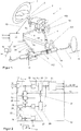
- the FIG. 1 shows an electric power steering 1 for a motor vehicle with a steering wheel 2, which is rotatably coupled to an upper steering shaft 3 and a lower steering shaft 4.
- the lower steering shaft 4 is in turn rotatably coupled to a steering pinion 5.
- the steering pinion 5 meshes in a known manner with a toothed segment of a rack 6.
- the rack 6 is slidably mounted in a steering housing in the direction of its longitudinal axis. At its free end, the rack 6 is connected to tie rods 7.
- the tie rods 7 themselves are connected in a known manner via steering knuckles, each with a steered wheel 8 of the motor vehicle.
- a rotation of the steering wheel 2 leads via the connection of the steering shaft 3, 4 and the pinion 5 to a longitudinal displacement of the rack 6 and thus to a pivoting of the steered wheels 8.
- the steered wheels 8 learn about a roadway a reaction that counteracts the steering movement , For pivoting the wheels 8 consequently a force is required which makes a corresponding torque on the steering wheel 2 required.
- a servo motor of a servo device 100, 101, 102 is provided to assist the driver in this steering movement.
- the servo device 100, 101, 102 can be arranged as a superposition steering on the steering column 100 or as an auxiliary power assist device on the pinion 101 or the rack 102.
- a torsion sensor 9 is provided, which detects a steering torque 10.
- This steering torque 10 is transmitted with further input variables 11, such as the vehicle speed, and measuring signals 54 from the electric motor, such as the current rotor position 19 and / or measured current values in the phase windings, to an engine control unit 12, which therefrom with the aid of a default function 13 guide variables or determines a desired current for the energization of the servomotor.
- the finally calculated manipulated variables or current values 51, 52, 53 are forwarded to the servo device 100, 101, 102 and the electric motor is operated accordingly.
- the noises 14 generated by the electric motor are measured in a measuring device 15 and passed on to the engine control unit 12 by means of a signal output 16.
- FIG. 2 the noise modulation of the electric motor according to the invention is explained.
- a dq nominal current i dref , i qref and a three-phase nominal current iuvw are determined in a first device 17 of the engine control unit 12.
- a control device 30 the known steering control takes place.
- a PI controller 18 controls a PI controller 18, the so-called steering controller, the dq setpoint voltages u dref , u qref according to these dq setpoints i dref , i qref and the dq state variables i d , i q , by means of a rotor position 19 and three-phase nominal current iuvw were determined.
- an inverse transformation 20 is carried out in order to transmit the voltage command values from the co-rotating coordinate system into a stationary coordinate system.
- the voltage command values are translated into electrical quantities.
- phase currents of the three motor phases U, V, W are generated according to the voltage command values by switching in the inverter MOSFET switches in certain patterns by a pulse width modulation drive.
- the phase currents 51, 52, 53 are forwarded to the servo device 100, 101, 102 for activation. You have the appropriate amount for a desired power steering.
- a device 22 initially checks the acoustic state, which was measured by the measuring device 15 and passed on to the engine control unit 12 by means of the signal output 16. In this case, according to a default function 23, a reference acoustic quantity is compared with the actual value of the signal input.
- the resulting deviation is translated via an NVH controller 24 and a coordinate transformation 25 into electrical, higher harmonic quantities and converted in a model / map 26 into dq current target variables, which are converted again via a PI controller 27 in a device 28 into physical controlled variables ,
- the actual and desired magnitudes become a more significant dimension corresponding to the acoustic problem, for example, an nth engine order, that is an nth harmonic of the engine speed corresponds, converted.
- the regulation thus no longer refers to the rotational coordinates but to multiples thereof, whereby the control frequency is artificially reduced.
- the state variables of the electric motor are first raised to a higher-value state (harmonic region) in the transformer 31.
- an adjustment is made to the current target values i dref n th, n th i qref which have been supplied from the device 22nd.
- the following PI controller 27 regulates the voltages, which subsequently have to be transformed back again.
- the voltages are fed into the controlled system after the device 20, and thus the voltage command values are adapted to the desired acoustic state before the phase currents are generated.
- the reference value of the d-component can be set variably.
- the radial portion of the field vector can be stimulated substantially free, which leads to the reduction of existing vibrations and noise emissions, for example by generating an antiphase sound emission, or for the free generation of sound emissions.
- the upstream devices 22 and 28 are referred to as acoustic controllers.
- the acoustic controller works model or map based. It is able to detect and convert vibro-acoustic disturbances that come from the steering or are transmitted via the steering, and convert it into a reference variable, which causes the control of the disturbance variable or the generation of a desired excitation.
- the acoustic controller is arranged on the engine control unit 12 together with the means 17, 18, 20 and 21.
- the d and q components can each be changed independently of each other.
- the quantities are physically coupled together due to the inductance of the electric motor. Therefore, effects of the upstream acoustic control on the steering behavior by tangential Force components in the engine can be prevented. This can be ensured, for example, by the utilization of the damping and the elasticity in the steering column. For this purpose, however, a minimum frequency of control must be observed. To ensure this minimum frequency of the control, the acoustic controller can not be connected upstream of the steering controller, since this has a low-pass behavior. For this reason, the acoustic control variable is first controlled separately and then charged according to the steering controller with the voltage command variables in rotation coordinates.
- the method according to the invention can be used for active compensation of electric motor noise during steering, for active compensation of driving vibrations transmitted via the steering line, for signal generation for driver assistance systems and for the active and authentic design of driving noise for electric vehicles.
- An operating point-dependent phase control is used to generate an excitation with a defined phase reference to the disturbance variable directly at the source.
- both the hardware (engine, engine control unit) and the software of conventional steering systems can be used unchanged. Additional actuators for active measures or complex secondary measures can be saved.
Landscapes
- Engineering & Computer Science (AREA)
- Power Engineering (AREA)
- Mechanical Engineering (AREA)
- Transportation (AREA)
- Chemical & Material Sciences (AREA)
- Combustion & Propulsion (AREA)
- General Engineering & Computer Science (AREA)
- Power Steering Mechanism (AREA)
- Control Of Ac Motors In General (AREA)
- Steering Control In Accordance With Driving Conditions (AREA)
Description
- Die vorliegende Erfindung betrifft ein Verfahren zur Geräuschmodulation eines Elektromotors mit den Merkmalen des Oberbegriffs des Anspruchs 1.
- Im Sinne der Erfindung sind unter dem Begriff "Geräusch" neben hörbaren Geräuschen auch Geräusche, die als Schwingungen wahrgenommen werden können subsumiert.
- Elektromotoren werden beispielsweise in Servolenkungen oder Überlagerungslenkungen von Kraftfahrzeugen zur Unterstützung eines vom Fahrer eingeleiteten Lenkradhandmoments oder Aufbringen eines Zusatzlenkwinkels eingesetzt. Bei elektromechanischen Lenkungen unterstützt und überlagert der Elektromotor an der Lenksäule oder dem Lenkgetriebe die Lenkbewegung des Fahrers.
- Im Betrieb erzeugt eine elektromechanische Lenkung, zum Beispiel bei Lenkbewegungen im Stand, akustische Emissionen, die auf den Elektromotor zurückzuführen sind. Die radialen Magnetfeldanteile des Elektromotors führen zu einer zyklischen Verformung des Motors, was eine akustische Abstrahlung verursacht.
- In modernen elektrischen Lenksystemen wird um die Positionsregelegung von Synchronmotoren präzise zu gestalten, eine feldorientierte Vektorregelung (FOR) eingesetzt. Hierzu wird das dreiphasige Stromsystem mit Hilfe der Lage des Rotors des Synchronmotors, insbesondere des Polradwinkels ϕ, in ein komplexes, orthogonales Rotorkoordinatensystem überführt. Daraus resultieren die gedrehten Stromkomponenten id und iq, wobei id dem Magnetisierungsstrom und iq dem Drehmoment bildenden Strom des Synchronmotors entsprechen. Bei der Ansteuerung des Synchronmotors wird vor allem das Drehmoment optimiert, indem in nachgeschalteten PI-Regelstufen die d-q-Sollgrößen für die jeweilige Betriebssituation optimal ausgelegt werden. Dabei wird insbesondere die Stromkomponente q in den nachgeschalteten PI-Regelstufen zur vibro-akustische Optimierungen des Lenksystems in Form von Ripplekompensation geregelt. Akustische Probleme, wie die typischen Störgeräusche von Elektromotoren werden über klassische Ansätze unter Verwendung von Sekundärmaßnahmen behandelt. Durch die Sekundärmaßnahmen wird das System hinsichtlich wichtiger Zielgrößen, wie zum Beispiel Leichtbau und Steifigkeit verschlechtert. Außerdem werden durch die zusätzlichen Maßnahmen die Kosten und der Herstellungsaufwand gesteigert.
- Bei elektromotorisch angetriebenen Fahrzeugen besteht insbesondere im Stadtverkehr das Problem, dass das Fahrzeug aufgrund der geringen Geräuschentwicklung akustisch verhältnismäßig schwer wahrnehmbar ist, was zu einem erhöhten Risiko führt. Um die Wahrnehmung zu verbessern, besteht beispielsweise die Möglichkeit, im Rangierbetrieb ein Warngeräusch zu erzeugen.
- Aus der
DE 10 2012 211 689 A1 ist ein Verfahren zur Geräuscherzeugung bekannt, bei dem die Bestromung des Elektromotors so modifiziert wird, dass die aus der Modifikation resultierende Änderung der Motorwellenumdrehung innerhalb einer definierten Toleranz liegt. Wie die Bestromung des Elektromotors genau moduliert wird, ist nicht offenbart. - In der JPH04200294 A ist ein Modulationsverfahren für einen Elektromotor zur Geräuschmodulation offenbart, bei dem der Motorstrom mit einer Trägerfrequenz moduliert wird, die ein Abbild der gewünschten Geräuschbildung ist. Dabei ist vorgesehen, die Störgeräusche des Motors durch eine Pulsweitenmodulation in ein musikalisches Intervall mit einer Melodie umzuwandeln. Nachteilig ist dabei, das entsprechend dem eingetragenen Geräusch die vom Elektromotor abgegebene Drehzahl und das abgegebene Drehmoment schwanken.
- Aus der Schrift
DE 10 2010 049359 A1 , welche den nächsten Stand der Technik nach dem Oberbegriff des Anspruchs 1 offenbart, ist ein Verfahren zur Geräuschmodulation eines Elektromotors bekannt, dabei wird ein Strom und eine Spannung des Elektromotors durch Aufmodulieren eines akustischen Signals derart gesteuert, dass der Elektromotor in Schwingungen versetzt wird, welche dem akustischen Signal entsprechen. - Der Erfindung liegt die Aufgabe zugrunde, ein Verfahren zur Geräuschmodulation eines Elektromotors anzugeben, bei dem die vom Elektromotor abgegebene Drehzahl und das vom Elektromotor abgegebene Drehmoment nur in sehr geringem Maße beeinflusst werden.
- Diese Aufgabe wird von einem Verfahren mit den Merkmalen des Anspruchs 1 gelöst.
- Danach ist Verfahren zur Geräuschmodulation eines Elektromotors, wobei der Elektromotor ein mehrphasiger Synchronmotor ist, der unter Verwendung einer Vektorregelung mittels eines Motorsteuergeräts angetrieben ist, wobei in einer Regelstrecke Istwerte für die gedrehten Stromkomponenten id und iq gewonnen werden, wobei id dem Magnetisierungsstrom und iq dem Drehmoment bildenden Strom des Synchronmotors entsprechen, und wobei die Istwerte mit vorgegebenen Führungsgrößen iq_soll, id_soll verglichen werden, wobei die Differenzen zwischen den Istwerten und den Führungsgrößen über einen ersten Regler und eine erste Transformationsstufe in einem Duty-Cycle für einen PWM-Generator in Stellgrößen umgerechnet werden, um die Ist-Werte iq, id auf die Führungsgrößen iq_soll, id_soll zu regeln, vorgesehen, bei dem die Magnetisierungsstrom bildende Stromkomponente id in Abhängigkeit von einem akustischen Zustand, der von einer Messeinrichtung gemessen und mittels einer Signalausgabe an das Motorsteuergerät weitergegeben wurde, mittels eines Akustikreglers an einen gewünschten akustischen Zustand angepasst wird. Durch dieses Verfahren zur Geräuschmodulation wird das vom Elektromotor abgegebene Drehmoment nur in sehr geringem Maße beeinflusst.
- Das Verfahren wird bevorzugt für einen dreiphasigen Synchronmotor eingesetzt.
- Bevorzugt wird in dem Akustikregler entsprechend einer Vorgabefunktion eine Referenz-Akustikgröße mit dem akustischen Zustand verglichen, die resultierende Abweichung wird in elektrische Größen übersetzt und in einem Modell/Kennfeld in dq-Stromzielgrößen umgerechnet.
- Mit Hilfe der erfindungsgemäßen Methode zur Geräuschmodulation können einerseits gezielt gewünschte Geräusche erzeugt werden, als auch Geräusche im Betrieb des Elektromotors verringert werden. Darüberhinaus können bei der Verwendung entsprechender Vorgabefunktionen für die Referenz-Akustikgröße auch gezielt andere Geräusche in Fahrzeugen beeinflusst werden. Dabei ist es auch denkbar und möglich durch entsprechend erzeugte phasenverschobene Schallemissionen im Elektromotor andere Fahrzeuggeräusche - im Sinne von Antischall - zu reduzieren oder auszulöschen.
- In einer bevorzugten Ausführungsform werden die dq-Stromzielgrößen über einen zweiten Regler und eine zweite Transformationsstufe in physikalische Regelgrößen umgewandelt werden, die mit den physikalische Regelgrößen der Regelstrecke nach der ersten Transformationsstufe verrechnet werden.
- Dabei ist es vorteilhaft, wenn die Akustikgrößen im Akustikregler in eine höherwertige Dimension umgerechnet werden.
- Vorzugsweise ist der Elektromotor Teil eines Kraftfahrzeugs und/oder Teil einer Servolenkung.
- Vorzugsweise wird das erfindungsgemäße Verfahren zur Geräuschmodulation als Verfahren zur Geräuschminderung in einem Kraftfahrzeug eingesetzt, bei dem ein Schallwert mit einer Sensorik ermittelt wird und daraus eine phasenverschobene Referenzakustikgröße bestimmt wird, die als Referenzwert für das zuvor ausgeführte Verfahren zur Geräuschmodulation des Elektromotors eingesetzt wird.
- Nachfolgend wird ein Ausführungsbeispiel der Erfindung anhand der Zeichnungen näher beschrieben. Es zeigen:
- Fig. 1:
- eine schematische Ansicht einer elektrischen Servolenkung, sowie
- Fig. 2:
- einen Regelkreis eines Motorsteuergeräts.
- Die
Figur 1 zeigt eine elektrische Servolenkung 1 für ein Kraftfahrzeug mit einem Lenkrad 2, das mit einer oberen Lenkwelle 3 und einer unteren Lenkwelle 4 drehfest gekoppelt ist. Die untere Lenkwelle 4 ist wiederum drehfest mit einem Lenkritzel 5 gekoppelt. Das Lenkritzel 5 kämmt in bekannter Weise mit einem Zahnsegment einer Zahnstange 6. Die Zahnstange 6 ist in einem Lenkungsgehäuse in Richtung ihrer Längsachse verschieblich gelagert. An ihrem freien Ende ist die Zahnstange 6 mit Spurstangen 7 verbunden. Die Spurstangen 7 selbst sind in bekannter Weise über Achsschenkel mit je einem gelenkten Rad 8 des Kraftfahrzeugs verbunden. Eine Drehung des Lenkrades 2 führt über die Verbindung der Lenkwelle 3, 4 und des Ritzels 5 zu einer Längsverschiebung der Zahnstange 6 und damit zu einer Verschwenkung der gelenkten Räder 8. Die gelenkten Räder 8 erfahren über eine Fahrbahn eine Rückwirkung, die der Lenkbewegung entgegen wirkt. Zum Verschwenken der Räder 8 ist folglich eine Kraft erforderlich, die ein entsprechendes Drehmoment am Lenkrad 2 erforderlich macht. Ein Servomotor einer Servoeinrichtung 100, 101, 102 ist vorgesehen, um dem Fahrer bei dieser Lenkbewegung zu unterstützen. Die Servoeinrichtung 100, 101, 102 kann dabei als Überlagerungslenkung an der Lenksäule 100 oder als Hilfskraftunterstützungseinrichtung an dem Ritzel 101 oder der Zahnstange 102 angeordnet sein. An der Lenkwelle ist ein Torsionssensor 9 vorgesehen, der ein Lenkdrehmoment 10 erfasst. Dieses Lenkdrehmoment 10 wird mit weiteren Eingangsgrößen 11, wie zum Beispiel der Fahrzeuggeschwindigkeit, und Messsignalen 54 vom Elektromotor, wie beispielsweise der momentanen Rotorposition 19 und/oder gemessener Stromwerte in den Phasenwicklungen, an ein Motorsteuergerät 12 übermittelt, welches daraus mit Hilfe einer Vorgabefunktion 13 Führungsgrößen bzw. einen Sollstrom für die Bestromung des Servomotors bestimmt. Der letztendlich berechneten Stellgrößen bzw. Stromwerte 51, 52, 53 werden an die Servoeinrichtung 100, 101, 102 weitergegeben und der Elektromotor entsprechend betrieben. Die vom Elektromotor erzeugten Geräusche 14 werden in einer Messeinrichtung 15 gemessen und mittels einer Signalausgabe 16 an das Motorsteuergerät 12 weitergegeben. - In der
Figur 2 ist die erfindungsgemäße Geräuschmodulation des Elektromotors erklärt.
Anhand des gemessenen Lenkdrehmoments 10, weiterer Eingangsgrößen 11 und einer Vorgabefunktion 13 wird in einer ersten Einrichtung 17 des Motorsteuergeräts 12 ein dq-Sollstrom idref, iqref und ein dreiphasigen Sollstrom iuvw bestimmt. In einer Steuereinrichtung 30 erfolgt die bekannte Lenkungsregelung. Im Beispiel regelt ein PI-Regler 18, der sogenannte Lenkungsregler, die dq-Sollspannungen udref, uqref gemäß dieser dq-Sollgrößen idref, iqref und der dq-Zustandsgrößen id, iq, die mittels einer Rotorposition 19 und dem dreiphasigen Sollstrom iuvw bestimmt wurden. Anschließend erfolgt mit Hilfe des Rotorwinkels Θ eine inverse Transformation 20, um die Spannungsbefehlswerte von dem mitdrehenden Koordinatensystem in ein ortsfestes Koordinatensystem zu übertragen. In einer Einrichtung 21 werden die Spannungsbefehlswerte in elektrische Größen übersetzt. Dabei werden die Phasenströme der drei Motorphasen U, V, W gemäß der Spannungsbefehlswerte erzeugt, indem in dem Inverter MosFET-Schalter in bestimmten Mustern durch eine Pulsweitenmodulation-Ansteuerung geschaltet werden. Die Phasenströme 51, 52, 53 werden an die Servoeinrichtung 100, 101, 102 zur Ansteuerung weitergeleitet. Sie besitzen den geeigneten Betrag für eine gewünschte Lenkhilfe.
Eine Einrichtung 22 überprüft zunächst den akustischen Zustand, der von der Messeinrichtung 15 gemessen und mittels der Signalausgabe 16 an das Motorsteuergerät 12 weitergegeben wurde. Dabei wird entsprechend einer Vorgabefunktion 23 eine Referenz-Akustikgröße mit dem Ist-Wert des Signaleingangs verglichen. Die resultierende Abweichung wird über einen NVH-Controller 24 und eine Koordinatentransformation 25 in elektrische, höherharmonische Größen übersetzt und in einem Modell/Kennfeld 26 in dq-Stromzielgrößen umgerechnet, die erneut über einen PI-Regler 27 in einer Einrichtung 28 in physikalische Regelgrößen umgewandelt werden. Um das Tiefpassverhalten des PI-Reglers 27 in der Einrichtung 28 zu umgehen, werden die Ist- und die Soll-Größen in einer höherwertigen Dimension, entsprechend dem akustischen Problem, zum Beispiel einer n-ten Motorordnung, die einer n-ten Harmonischen der Motordrehzahl entspricht, umgerechnet. Die Regelung bezieht sich somit nicht mehr auf die Drehkoordinaten, sondern auf Vielfache davon, wodurch die Regelungsfrequenz künstlich verringert wird. - In der Einrichtung 28, die als By-Pass zum Lenkungsregler 18 angesehen werden kann, werden ebenfalls elektrisch höherharmonische Referenzwerte als Sollgröße verwendet. Dazu werden die Zustandsgrößen des Elektromotors zunächst in einen höherwertigen Zustand (Oberwellenbereich) im Transformer 31 angehoben. Nach erneuter Koordinatentransformation im Transformer 32 erfolgt ein Abgleich mit den Stromzielgrößen idrefnth, iqrefnth, die aus der Einrichtung 22 zugeführt wurden. Der darauf folgende PI-Regler 27 regelt die Spannungen, die anschließend wiederum zurück transformiert werden müssen. Nach dieser inversen Transformation 29 werden die Spannungen nach der Einrichtung 20 in die Regelstrecke eingespeist und somit die Spannungsbefehlswerte vor der Erzeugung der Phasenströme an den gewünschten akustischen Zustand angepasst.
- Wie in
Figur 2 dargestellt, kann der Referenzwert des d-Anteils variabel eingestellt werden. Damit kann der radiale Anteil des Feldvektors im Wesentlichen frei stimuliert werden, was zur Verminderung von vorhandenen Schwingungen und Schallemissionen, zum Beispiel durch Erzeugung einer gegenphasigen Schallemission, bzw. zur freien Erzeugung von Schallemissionen führt. - Die vorgeschalteten Einrichtungen 22 und 28 werden als Akustikregler bezeichnet. Der Akustikregler arbeitet modell- oder kennfeldbasiert. Er ist in der Lage vibro-akustische Störgrößen, die aus der Lenkung kommen oder über die Lenkung übertragen werden, zu erfassen und in eine Referenzgröße zu konvertieren, die die Ausregelung der Störgröße bzw. die Erzeugung einer gewollten Anregung bewirkt. Der Akustikregler ist zusammen mit den Einrichtungen 17, 18, 20 und 21 auf dem Motorsteuergerät 12 angeordnet.
- Die d- und q-Anteile können jeweils unabhängig voneinander verändert werden. Jedoch sind die Größen physikalisch aufgrund der Induktivität des Elektromotors miteinander gekoppelt. Daher müssen Auswirkungen des vorgeschalteten Akustikreglers auf das Lenkverhalten durch tangentiale Kraftanteile im Motor verhindert werden. Dies kann zum Beispiel durch die Ausnutzung der Dämpfung und der Elastizität im Lenkstrang gewährleistest werden. Hierzu ist jedoch eine Mindestfrequenz der Regelung einzuhalten. Um diese Mindestfrequenz der Regelung zu gewährleisten, kann der Akustikregler nicht dem Lenkungsregler vorgeschaltet werden, da dieser ein Tiefpassverhalten aufweist. Aus diesem Grund wird die Akustikstellgröße erst separat geregelt und dann nach dem Lenkungsregler mit den Spannungsbefehlsgrößen in Rotationskoordinaten verrechnet.
- Die erfindungsgemäße Verfahren kann zur aktiven Kompensation von Elektromotorstörgeräuschen bei der Lenkung, zur aktiven Kompensation von über den Lenkstrang übertragene fahrbahnerregte Vibrationen, zur Signalerzeugung für Fahrerassistenzsysteme und zur aktiven und authentischen Gestaltung eines Fahrgeräusches für Elektrofahrzeuge eingesetzt werden.
- Es wird eine betriebspunktabhängige Phasenregelung verwendet, um eine Anregung mit einem definierten Phasenbezug zur Störgröße unmittelbar an der Quelle zu erzeugen. Dabei kann sowohl die Hardware (Motor, Motorsteuergerät) als auch die Software von herkömmlichen Lenksystemen unverändert verwendet werden. Zusätzliche Aktuatoren für aktive Maßnahmen bzw. aufwendige Sekundärmaßnahmen können eingespart werden.
Claims (8)
- Verfahren zur Geräuschmodulation eines Elektromotors, wobei der Elektromotor ein mehrphasiger Synchronmotor ist, der unter Verwendung einer Vektorregelung mittels eines Motorsteuergeräts (12) angetrieben ist, wobei in einer Regelstrecke Istwerte für die gedrehten Stromkomponenten id und iq gewonnen werden, wobei id dem Magnetisierungsstrom und iq dem Drehmoment bildenden Strom des Synchronmotors entsprechen, und wobei die Istwerte mit vorgegebenen Führungsgrößen (iq_soll, id_soll) verglichen werden, wobei die Differenzen zwischen den Istwerten und den Führungsgrößen über einen ersten Regler (18) und eine erste Transformationsstufe (20) in einem Duty-Cycle für einen PWM-Generator in Stellgrößen umgerechnet werden, um die Ist-Werte (iq, id) auf die Führungsgrößen (iq_soll, id_soll) zu regeln, dadurch gekennzeichnet, dass die den Magnetisierungsstrom bildende Stromkomponente (id) in Abhängigkeit von einem akustischen Zustand, der von einer Messeinrichtung (15) gemessen und mittels einer Signalausgabe (16) an das Motorsteuergerät (12) weitergegeben wurde, mittels eines Akustikreglers (22, 28) an einen gewünschten akustischen Zustand angepasst wird.
- Verfahren zu Geräuschmodulation nach Anspruch 1, dadurch gekennzeichnet, dass der Elektromotor ein dreiphasiger Synchronmotor ist.
- Verfahren zur Geräuschmodulation eines Elektromotors nach Anspruch 1 oder 2, dadurch gekennzeichnet, dass in dem Akustikregler (22, 28) entsprechend einer Vorgabefunktion (23) eine Referenz-Akustikgröße mit dem akustischen Zustand verglichen wird, die resultierende Abweichung in elektrische Größen übersetzt und in einem Modell/Kennfeld (26) in dq-Stromzielgrößen umgerechnet wird.
- Verfahren zur Geräuschmodulation eines Elektromotors nach einem der vorhergehenden Ansprüche, dadurch gekennzeichnet, dass die dq-Stromzielgrößen über einen zweiten Regler (27) und eine zweite Transformationsstufe (29) in physikalische Regelgrößen umgewandelt werden, die mit den physikalische Regelgrößen der Regelstrecke nach der ersten Transformationsstufe (20) verrechnet werden.
- Verfahren zur Geräuschmodulation eines Elektromotors nach einem der vorhergehenden Ansprüche, dadurch gekennzeichnet, dass die Akustikgrößen im Akustikregler (22, 28) in eine höherwertige Dimension umgerechnet werden.
- Verfahren zur Geräuschmodulation eines Elektromotors nach einem der vorhergehenden Ansprüche, dadurch gekennzeichnet, dass der Elektromotor Teil eines Kraftfahrzeugs ist.
- Verfahren zur Geräuschmodulation eines Elektromotors nach einem der vorhergehenden Ansprüche, dadurch gekennzeichnet, dass der Elektromotor Teil einer Servolenkung ist.
- Verfahren zur Geräuschminderung in einem Kraftfahrzeug, bei dem ein Schallwert mit einer Sensorik ermittelt wird und daraus eine phasenverschobene Referenzakustikgröße bestimmt wird, die als Referenzwert für das Verfahren zur Geräuschmodulation des Elektromotors entsprechend den Ansprüchen 3 bis 6 eingesetzt wird.
Applications Claiming Priority (2)
| Application Number | Priority Date | Filing Date | Title |
|---|---|---|---|
| DE102014007502.8A DE102014007502A1 (de) | 2014-05-23 | 2014-05-23 | Verfahren zur Geräuschminderung und Geräuschmodulation eines Elektromotors |
| PCT/EP2015/058569 WO2015176895A1 (de) | 2014-05-23 | 2015-04-21 | Verfahren zur geräuschminderung und geräuschmodulation eines elektromotors |
Publications (2)
| Publication Number | Publication Date |
|---|---|
| EP3145792A1 EP3145792A1 (de) | 2017-03-29 |
| EP3145792B1 true EP3145792B1 (de) | 2018-04-11 |
Family
ID=52998140
Family Applications (1)
| Application Number | Title | Priority Date | Filing Date |
|---|---|---|---|
| EP15718205.6A Active EP3145792B1 (de) | 2014-05-23 | 2015-04-21 | Verfahren zur geräuschminderung und geräuschmodulation eines elektromotors |
Country Status (5)
| Country | Link |
|---|---|
| US (1) | US9998051B2 (de) |
| EP (1) | EP3145792B1 (de) |
| CN (1) | CN106797193B (de) |
| DE (2) | DE202014010397U1 (de) |
| WO (1) | WO2015176895A1 (de) |
Cited By (1)
| Publication number | Priority date | Publication date | Assignee | Title |
|---|---|---|---|---|
| WO2024256541A1 (de) | 2023-06-14 | 2024-12-19 | Brose Fahrzeugteile SE & Co. Kommanditgesellschaft, Würzburg | Verfahren zum betrieb einer vorrichtung mit einem elektromotor und mit einem soundmodul |
Families Citing this family (26)
| Publication number | Priority date | Publication date | Assignee | Title |
|---|---|---|---|---|
| DE102015122194A1 (de) | 2015-12-18 | 2017-06-22 | Robert Bosch Automotive Steering Gmbh | Verfahren zur Maskierung und/oder zur Reduzierung störender Geräusche oder deren Auffälligkeit bei dem Betrieb eines Kraftfahrzeugs |
| WO2018036615A1 (en) | 2016-08-23 | 2018-03-01 | Thyssenkrupp Presta Ag | Moisture sensing in electric motors of motor vehicle steering systems with pull up resistor |
| DE102016219147B4 (de) | 2016-10-04 | 2026-03-12 | Bayerische Motoren Werke Aktiengesellschaft | Verfahren zur Reduzierung von Schall und/oder Drehmomentwelligkeit bei fremderregten elektrischen Maschinen |
| CN106502305B (zh) * | 2016-11-24 | 2017-11-10 | 兰州飞行控制有限责任公司 | 一种并联舵机脉宽调制驱动信号的确定方法 |
| US10319360B1 (en) | 2018-03-06 | 2019-06-11 | GM Global Technology Operations LLC | Active masking of tonal noise using motor-based acoustic generator to improve sound quality |
| DE102018115148A1 (de) | 2018-05-08 | 2019-11-14 | Hochschule für angewandte Wissenschaften München | Verfahren zur Erzeugung und/oder Kompensation von Schwingungen mittels eines Elektromotors |
| DE102018210402A1 (de) * | 2018-06-26 | 2020-01-02 | Robert Bosch Gmbh | Verfahren zum Ansteuern eines Stellantriebs |
| DE102019101360A1 (de) * | 2019-01-21 | 2020-07-23 | Dr. Ing. H.C. F. Porsche Aktiengesellschaft | Luftfahrzeug |
| DE102019105118B4 (de) * | 2019-02-28 | 2022-03-03 | Dr. Ing. H.C. F. Porsche Aktiengesellschaft | Verfahren zum Ansteuern eines elektromotorischen Lenkungsaktuators und Kraftfahrzeug |
| KR102706259B1 (ko) * | 2019-08-09 | 2024-09-11 | 현대자동차주식회사 | 모터를 이용한 능동 사운드 발생장치 |
| JP7287218B2 (ja) * | 2019-09-26 | 2023-06-06 | ニデックパワートレインシステムズ株式会社 | 電動オイルポンプの制御装置、電動オイルポンプ |
| DE102019008104A1 (de) * | 2019-11-21 | 2021-05-27 | Vat Holding Ag | Verfahren zur Überwachung, Positionsbestimmung und Positionierung eines Stiffthubsystems |
| DE102020116451B4 (de) | 2020-06-23 | 2024-02-08 | Dr. Ing. H.C. F. Porsche Aktiengesellschaft | Vorrichtung und Verfahren für aktive Geräuschunterdrückung bei einem Fahrzeug |
| DE102020117821B3 (de) | 2020-07-07 | 2021-11-04 | Dr. Ing. H.C. F. Porsche Aktiengesellschaft | Steuereinheit zum Erzeugen von PWM-Pulsen für einen Wechselrichter, insbesondere für einen Wechselrichter eines Antriebsstranges, Antriebsstrang mit einer elektrischen Maschine, Verfahren zum Betrieb eines Antriebsstranges, Kraftfahrzeug |
| DE102020119700A1 (de) | 2020-07-27 | 2022-01-27 | Bayerische Motoren Werke Aktiengesellschaft | Verfahren und Vorrichtung zur aktiven Störgeräuschunterdrückung |
| DE102020122099A1 (de) | 2020-09-04 | 2022-03-10 | Schaeffler Technologies AG & Co. KG | Verfahren zur Modulation der Drehmomentwelligkeit und/oder der Radialkraft einer drehstrombetriebenen elektrischen Maschine |
| DE102020211511A1 (de) | 2020-09-14 | 2022-03-17 | Vitesco Technologies GmbH | Verfahren zum Anpassen von Strukturschwingungen einer elektrischen Maschine und entsprechende Steuereinrichtung |
| DE102021213271B4 (de) | 2021-11-25 | 2023-08-10 | Vitesco Technologies GmbH | Verfahren zur Geräuschreduktion im Betrieb eines Elektromotors, sowie Motorsteuervorrichtung zur Steuerung des Betriebs eines Elektromotors mit Geräuschreduktion |
| JP7818481B2 (ja) * | 2022-07-08 | 2026-02-20 | 株式会社ジェイテクト | 操舵制御装置 |
| JP7818482B2 (ja) * | 2022-07-08 | 2026-02-20 | 株式会社ジェイテクト | 操舵制御装置 |
| CN115842492B (zh) * | 2022-11-01 | 2026-04-07 | 联合汽车电子有限公司 | 一种惯性位移标定方法、装置、介质、控制器及升降总成 |
| DE102022211882A1 (de) * | 2022-11-10 | 2024-05-16 | Zf Friedrichshafen Ag | Verfahren zur Steuerung eines Betriebs einer elektrischen Maschine eines Kraftfahrzeugs |
| DE102023202242A1 (de) * | 2023-03-13 | 2024-09-19 | Zf Friedrichshafen Ag | Schallkompensationsvorrichtung für einen im Bereich einer Achse eines Fahrzeugs angeordneten Aktuator |
| DE102023121693A1 (de) * | 2023-08-14 | 2025-02-20 | Rolls-Royce Deutschland Ltd & Co Kg | Verfahren zur lärm- und vibrationsreduzierenden Steuerung einer Antriebseinheit und entsprechende Antriebseinheit |
| DE102023129898A1 (de) | 2023-10-30 | 2025-04-30 | Schaeffler Technologies AG & Co. KG | Reglungsvorrichtung, Verfahren zur Kompensation von auf eine elektrische Maschine bei deren Betrieb einwirkenden Erregungsordnungen, Computerprogrammprodukt, elektrische Maschine sowie elektrischer Achsantriebsstrang |
| DE102024208844A1 (de) | 2024-09-17 | 2026-03-19 | Schaeffler Technologies AG & Co. KG | Elektrische Antriebseinrichtung |
Family Cites Families (13)
| Publication number | Priority date | Publication date | Assignee | Title |
|---|---|---|---|---|
| JPH04200294A (ja) | 1990-11-29 | 1992-07-21 | Toshiba Corp | インバータ装置 |
| JP4385821B2 (ja) * | 2004-03-30 | 2009-12-16 | トヨタ自動車株式会社 | 車両搭載作動装置の制御装置および波動強度特性取得装置 |
| US7327111B2 (en) * | 2005-08-12 | 2008-02-05 | Siemens Energy & Automation, Inc. | System and method for parallel control of variable frequency drives |
| WO2007046435A1 (ja) * | 2005-10-21 | 2007-04-26 | Matsushita Electric Industrial Co., Ltd. | 騒音制御装置 |
| US8212505B2 (en) * | 2008-12-02 | 2012-07-03 | GM Global Technology Operations LLC | Method and system for creating a vibration in an automobile |
| DE102010049359A1 (de) * | 2010-10-23 | 2011-05-19 | Daimler Ag | Verfahren zur Ausgabe von akustischen Signalen |
| DE102011004384A1 (de) * | 2011-02-18 | 2012-08-23 | Zf Lenksysteme Gmbh | Verbesserung der Akustik durch Kompensation |
| JP5835091B2 (ja) * | 2012-05-11 | 2015-12-24 | 日本精工株式会社 | 電動パワーステアリング装置 |
| DE102012211689A1 (de) | 2012-07-05 | 2014-01-09 | Robert Bosch Gmbh | Verfahren zur Geräuscherzeugung in einem Fahrzeug mit einem Elektromotor |
| JP6070925B2 (ja) * | 2012-08-24 | 2017-02-01 | 富士電機株式会社 | 電動機駆動システム |
| US9143081B2 (en) * | 2013-03-14 | 2015-09-22 | Steering Solutions Ip Holding Corporation | Motor control system having bandwidth compensation |
| WO2014177144A2 (de) * | 2013-04-30 | 2014-11-06 | Schaeffler Technologies Gmbh & Co. Kg | Verfahren zum betrieb eines elektromotors |
| CN103631989B (zh) * | 2013-10-23 | 2016-08-17 | 江苏大学 | 一种离心泵流动诱导噪声数值预测方法 |
-
2014
- 2014-05-23 DE DE202014010397.6U patent/DE202014010397U1/de not_active Expired - Lifetime
- 2014-05-23 DE DE102014007502.8A patent/DE102014007502A1/de not_active Ceased
-
2015
- 2015-04-21 CN CN201580026856.9A patent/CN106797193B/zh active Active
- 2015-04-21 EP EP15718205.6A patent/EP3145792B1/de active Active
- 2015-04-21 US US15/313,344 patent/US9998051B2/en active Active
- 2015-04-21 WO PCT/EP2015/058569 patent/WO2015176895A1/de not_active Ceased
Cited By (2)
| Publication number | Priority date | Publication date | Assignee | Title |
|---|---|---|---|---|
| WO2024256541A1 (de) | 2023-06-14 | 2024-12-19 | Brose Fahrzeugteile SE & Co. Kommanditgesellschaft, Würzburg | Verfahren zum betrieb einer vorrichtung mit einem elektromotor und mit einem soundmodul |
| DE102023205569A1 (de) | 2023-06-14 | 2024-12-19 | Brose Fahrzeugteile SE & Co. Kommanditgesellschaft, Würzburg | Verfahren zum Betrieb einer Vorrichtung mit einem Elektromotor und mit einem Soundmodul |
Also Published As
| Publication number | Publication date |
|---|---|
| WO2015176895A1 (de) | 2015-11-26 |
| EP3145792A1 (de) | 2017-03-29 |
| CN106797193A (zh) | 2017-05-31 |
| DE102014007502A1 (de) | 2015-11-26 |
| CN106797193B (zh) | 2019-08-20 |
| US9998051B2 (en) | 2018-06-12 |
| US20170187313A1 (en) | 2017-06-29 |
| DE202014010397U1 (de) | 2015-08-03 |
Similar Documents
| Publication | Publication Date | Title |
|---|---|---|
| WO2015176895A1 (de) | Verfahren zur geräuschminderung und geräuschmodulation eines elektromotors | |
| DE60318630T2 (de) | Elektrische Servolenkung | |
| DE102018112207B4 (de) | Vorrichtung und Verfahren zur Steuerung eines Motors für elektrische Servolenkung | |
| DE102011051232B4 (de) | Motoransteuervorrichtung und elektrisches Lenkhilfesystem, welches dieselbe verwendet | |
| DE102017210304B4 (de) | Vorrrichtung zur steuerung einer dreiphasigen rotierenden elektrischen maschine zur reduzierung des spitzenwerts des phasenstroms | |
| DE10256921A1 (de) | Elektrische Servolenkvorrichtung | |
| DE112015002435T5 (de) | Fahrunterstützungsvorrichtung und Verfahren eines Steuerns/Regelns einer Fahrunterstützungsvorrichtung | |
| DE102009056720A1 (de) | Fahrzeuglenkungs-Steuervorrichtung und deren Verfahren | |
| DE102015213304A1 (de) | Elektromechanische Servolenkung | |
| DE112020003779B4 (de) | Elektrische servolenkungsvorrichtung, steuervorrichtung für eine elektrische servolenkungsvorrichtung und steuerverfahren | |
| EP1845007A1 (de) | Verfahren zum Betrieb eines elektrischen Servolenksystems | |
| DE102005052015B4 (de) | Motorsteuerung und Lenkvorrichtung | |
| EP3593448A1 (de) | Regelvorrichtung für eine elektrische maschine, elektrisches antriebssystem und verfahren zur regelung einer elektrischen maschine | |
| DE112016003033T5 (de) | Motorsteuervorrichtung und damit ausgerüstete elektrische Servolenkvorrichtung | |
| DE102012211689A1 (de) | Verfahren zur Geräuscherzeugung in einem Fahrzeug mit einem Elektromotor | |
| DE102019214446A1 (de) | Verfahren und Vorrichtung zur simultanen lateralen Fahrzeugführung durch Fahrer und Assistenzsystem bei elektrischen Lenkaktoren | |
| EP1699676B1 (de) | Verfahren zum abbremsen eines elektromotors und elektrischer antrieb | |
| EP1521701B1 (de) | Verfahren zum lenken eines fahrzeugs mit einer überlagerungslenkung | |
| DE102008055875B4 (de) | Elektromechanisches Servo-Lenksystem und Verfahren zum Betreiben eines elektromechanischen Servo-Lenksystems für Fahrzeuge | |
| DE102010043297A1 (de) | Elektrische Servolenkungsapparatur | |
| EP3695509A1 (de) | Verfahren zum wechseln zwischen blockansteuerung und pwm-ansteuerung einer elektrischen maschine | |
| EP1508493A2 (de) | Lenksystem für ein Kraftfahrzeug mit einer Servolenkung | |
| EP2082944B1 (de) | Verfahren zum Erzeugen eins Rückführdrehmoment-Signals | |
| DE112020003777B4 (de) | Elektrischer servolenkapparat, steuervorrichtung, die in einem elektrischen servolenkapparat verwendet wird, und steuerverfahren | |
| WO2015185439A1 (de) | Verfahren und vorrichtung zur steuerung eines betriebs eines elektromotors |
Legal Events
| Date | Code | Title | Description |
|---|---|---|---|
| PUAI | Public reference made under article 153(3) epc to a published international application that has entered the european phase |
Free format text: ORIGINAL CODE: 0009012 |
|
| 17P | Request for examination filed |
Effective date: 20161207 |
|
| AK | Designated contracting states |
Kind code of ref document: A1 Designated state(s): AL AT BE BG CH CY CZ DE DK EE ES FI FR GB GR HR HU IE IS IT LI LT LU LV MC MK MT NL NO PL PT RO RS SE SI SK SM TR |
|
| AX | Request for extension of the european patent |
Extension state: BA ME |
|
| RIC1 | Information provided on ipc code assigned before grant |
Ipc: B62D 5/04 20060101AFI20170412BHEP Ipc: H02P 29/50 20160101ALI20170412BHEP |
|
| RAP1 | Party data changed (applicant data changed or rights of an application transferred) |
Owner name: THYSSENKRUPP AG Owner name: THYSSENKRUPP PRESTA AG Owner name: HOCHSCHULE MUENCHEN |
|
| DAV | Request for validation of the european patent (deleted) | ||
| DAX | Request for extension of the european patent (deleted) | ||
| GRAP | Despatch of communication of intention to grant a patent |
Free format text: ORIGINAL CODE: EPIDOSNIGR1 |
|
| INTG | Intention to grant announced |
Effective date: 20171116 |
|
| GRAS | Grant fee paid |
Free format text: ORIGINAL CODE: EPIDOSNIGR3 |
|
| GRAA | (expected) grant |
Free format text: ORIGINAL CODE: 0009210 |
|
| AK | Designated contracting states |
Kind code of ref document: B1 Designated state(s): AL AT BE BG CH CY CZ DE DK EE ES FI FR GB GR HR HU IE IS IT LI LT LU LV MC MK MT NL NO PL PT RO RS SE SI SK SM TR |
|
| REG | Reference to a national code |
Ref country code: GB Ref legal event code: FG4D Free format text: NOT ENGLISH |
|
| REG | Reference to a national code |
Ref country code: CH Ref legal event code: EP |
|
| REG | Reference to a national code |
Ref country code: AT Ref legal event code: REF Ref document number: 987704 Country of ref document: AT Kind code of ref document: T Effective date: 20180415 |
|
| REG | Reference to a national code |
Ref country code: FR Ref legal event code: PLFP Year of fee payment: 4 |
|
| REG | Reference to a national code |
Ref country code: IE Ref legal event code: FG4D Free format text: LANGUAGE OF EP DOCUMENT: GERMAN |
|
| REG | Reference to a national code |
Ref country code: DE Ref legal event code: R096 Ref document number: 502015003852 Country of ref document: DE |
|
| REG | Reference to a national code |
Ref country code: NL Ref legal event code: MP Effective date: 20180411 |
|
| REG | Reference to a national code |
Ref country code: LT Ref legal event code: MG4D |
|
| PG25 | Lapsed in a contracting state [announced via postgrant information from national office to epo] |
Ref country code: NL Free format text: LAPSE BECAUSE OF FAILURE TO SUBMIT A TRANSLATION OF THE DESCRIPTION OR TO PAY THE FEE WITHIN THE PRESCRIBED TIME-LIMIT Effective date: 20180411 |
|
| PG25 | Lapsed in a contracting state [announced via postgrant information from national office to epo] |
Ref country code: PL Free format text: LAPSE BECAUSE OF FAILURE TO SUBMIT A TRANSLATION OF THE DESCRIPTION OR TO PAY THE FEE WITHIN THE PRESCRIBED TIME-LIMIT Effective date: 20180411 Ref country code: FI Free format text: LAPSE BECAUSE OF FAILURE TO SUBMIT A TRANSLATION OF THE DESCRIPTION OR TO PAY THE FEE WITHIN THE PRESCRIBED TIME-LIMIT Effective date: 20180411 Ref country code: BG Free format text: LAPSE BECAUSE OF FAILURE TO SUBMIT A TRANSLATION OF THE DESCRIPTION OR TO PAY THE FEE WITHIN THE PRESCRIBED TIME-LIMIT Effective date: 20180711 Ref country code: LT Free format text: LAPSE BECAUSE OF FAILURE TO SUBMIT A TRANSLATION OF THE DESCRIPTION OR TO PAY THE FEE WITHIN THE PRESCRIBED TIME-LIMIT Effective date: 20180411 Ref country code: SE Free format text: LAPSE BECAUSE OF FAILURE TO SUBMIT A TRANSLATION OF THE DESCRIPTION OR TO PAY THE FEE WITHIN THE PRESCRIBED TIME-LIMIT Effective date: 20180411 Ref country code: NO Free format text: LAPSE BECAUSE OF FAILURE TO SUBMIT A TRANSLATION OF THE DESCRIPTION OR TO PAY THE FEE WITHIN THE PRESCRIBED TIME-LIMIT Effective date: 20180711 Ref country code: AL Free format text: LAPSE BECAUSE OF FAILURE TO SUBMIT A TRANSLATION OF THE DESCRIPTION OR TO PAY THE FEE WITHIN THE PRESCRIBED TIME-LIMIT Effective date: 20180411 Ref country code: ES Free format text: LAPSE BECAUSE OF FAILURE TO SUBMIT A TRANSLATION OF THE DESCRIPTION OR TO PAY THE FEE WITHIN THE PRESCRIBED TIME-LIMIT Effective date: 20180411 |
|
| PG25 | Lapsed in a contracting state [announced via postgrant information from national office to epo] |
Ref country code: GR Free format text: LAPSE BECAUSE OF FAILURE TO SUBMIT A TRANSLATION OF THE DESCRIPTION OR TO PAY THE FEE WITHIN THE PRESCRIBED TIME-LIMIT Effective date: 20180712 Ref country code: RS Free format text: LAPSE BECAUSE OF FAILURE TO SUBMIT A TRANSLATION OF THE DESCRIPTION OR TO PAY THE FEE WITHIN THE PRESCRIBED TIME-LIMIT Effective date: 20180411 Ref country code: HR Free format text: LAPSE BECAUSE OF FAILURE TO SUBMIT A TRANSLATION OF THE DESCRIPTION OR TO PAY THE FEE WITHIN THE PRESCRIBED TIME-LIMIT Effective date: 20180411 Ref country code: LV Free format text: LAPSE BECAUSE OF FAILURE TO SUBMIT A TRANSLATION OF THE DESCRIPTION OR TO PAY THE FEE WITHIN THE PRESCRIBED TIME-LIMIT Effective date: 20180411 |
|
| REG | Reference to a national code |
Ref country code: CH Ref legal event code: PL |
|
| REG | Reference to a national code |
Ref country code: BE Ref legal event code: MM Effective date: 20180430 |
|
| PG25 | Lapsed in a contracting state [announced via postgrant information from national office to epo] |
Ref country code: PT Free format text: LAPSE BECAUSE OF FAILURE TO SUBMIT A TRANSLATION OF THE DESCRIPTION OR TO PAY THE FEE WITHIN THE PRESCRIBED TIME-LIMIT Effective date: 20180813 |
|
| REG | Reference to a national code |
Ref country code: DE Ref legal event code: R097 Ref document number: 502015003852 Country of ref document: DE |
|
| REG | Reference to a national code |
Ref country code: IE Ref legal event code: MM4A |
|
| PG25 | Lapsed in a contracting state [announced via postgrant information from national office to epo] |
Ref country code: MC Free format text: LAPSE BECAUSE OF FAILURE TO SUBMIT A TRANSLATION OF THE DESCRIPTION OR TO PAY THE FEE WITHIN THE PRESCRIBED TIME-LIMIT Effective date: 20180411 Ref country code: LU Free format text: LAPSE BECAUSE OF NON-PAYMENT OF DUE FEES Effective date: 20180421 Ref country code: EE Free format text: LAPSE BECAUSE OF FAILURE TO SUBMIT A TRANSLATION OF THE DESCRIPTION OR TO PAY THE FEE WITHIN THE PRESCRIBED TIME-LIMIT Effective date: 20180411 Ref country code: DK Free format text: LAPSE BECAUSE OF FAILURE TO SUBMIT A TRANSLATION OF THE DESCRIPTION OR TO PAY THE FEE WITHIN THE PRESCRIBED TIME-LIMIT Effective date: 20180411 Ref country code: RO Free format text: LAPSE BECAUSE OF FAILURE TO SUBMIT A TRANSLATION OF THE DESCRIPTION OR TO PAY THE FEE WITHIN THE PRESCRIBED TIME-LIMIT Effective date: 20180411 Ref country code: CZ Free format text: LAPSE BECAUSE OF FAILURE TO SUBMIT A TRANSLATION OF THE DESCRIPTION OR TO PAY THE FEE WITHIN THE PRESCRIBED TIME-LIMIT Effective date: 20180411 Ref country code: SK Free format text: LAPSE BECAUSE OF FAILURE TO SUBMIT A TRANSLATION OF THE DESCRIPTION OR TO PAY THE FEE WITHIN THE PRESCRIBED TIME-LIMIT Effective date: 20180411 |
|
| PLBE | No opposition filed within time limit |
Free format text: ORIGINAL CODE: 0009261 |
|
| STAA | Information on the status of an ep patent application or granted ep patent |
Free format text: STATUS: NO OPPOSITION FILED WITHIN TIME LIMIT |
|
| PG25 | Lapsed in a contracting state [announced via postgrant information from national office to epo] |
Ref country code: BE Free format text: LAPSE BECAUSE OF NON-PAYMENT OF DUE FEES Effective date: 20180430 Ref country code: CH Free format text: LAPSE BECAUSE OF NON-PAYMENT OF DUE FEES Effective date: 20180430 Ref country code: LI Free format text: LAPSE BECAUSE OF NON-PAYMENT OF DUE FEES Effective date: 20180430 Ref country code: IT Free format text: LAPSE BECAUSE OF FAILURE TO SUBMIT A TRANSLATION OF THE DESCRIPTION OR TO PAY THE FEE WITHIN THE PRESCRIBED TIME-LIMIT Effective date: 20180411 Ref country code: SM Free format text: LAPSE BECAUSE OF FAILURE TO SUBMIT A TRANSLATION OF THE DESCRIPTION OR TO PAY THE FEE WITHIN THE PRESCRIBED TIME-LIMIT Effective date: 20180411 |
|
| 26N | No opposition filed |
Effective date: 20190114 |
|
| PG25 | Lapsed in a contracting state [announced via postgrant information from national office to epo] |
Ref country code: IE Free format text: LAPSE BECAUSE OF NON-PAYMENT OF DUE FEES Effective date: 20180421 |
|
| PG25 | Lapsed in a contracting state [announced via postgrant information from national office to epo] |
Ref country code: SI Free format text: LAPSE BECAUSE OF FAILURE TO SUBMIT A TRANSLATION OF THE DESCRIPTION OR TO PAY THE FEE WITHIN THE PRESCRIBED TIME-LIMIT Effective date: 20180411 |
|
| PG25 | Lapsed in a contracting state [announced via postgrant information from national office to epo] |
Ref country code: MT Free format text: LAPSE BECAUSE OF FAILURE TO SUBMIT A TRANSLATION OF THE DESCRIPTION OR TO PAY THE FEE WITHIN THE PRESCRIBED TIME-LIMIT Effective date: 20180411 |
|
| PG25 | Lapsed in a contracting state [announced via postgrant information from national office to epo] |
Ref country code: TR Free format text: LAPSE BECAUSE OF FAILURE TO SUBMIT A TRANSLATION OF THE DESCRIPTION OR TO PAY THE FEE WITHIN THE PRESCRIBED TIME-LIMIT Effective date: 20180411 |
|
| PG25 | Lapsed in a contracting state [announced via postgrant information from national office to epo] |
Ref country code: MK Free format text: LAPSE BECAUSE OF NON-PAYMENT OF DUE FEES Effective date: 20180411 Ref country code: HU Free format text: LAPSE BECAUSE OF FAILURE TO SUBMIT A TRANSLATION OF THE DESCRIPTION OR TO PAY THE FEE WITHIN THE PRESCRIBED TIME-LIMIT; INVALID AB INITIO Effective date: 20150421 Ref country code: CY Free format text: LAPSE BECAUSE OF FAILURE TO SUBMIT A TRANSLATION OF THE DESCRIPTION OR TO PAY THE FEE WITHIN THE PRESCRIBED TIME-LIMIT Effective date: 20180411 |
|
| PG25 | Lapsed in a contracting state [announced via postgrant information from national office to epo] |
Ref country code: IS Free format text: LAPSE BECAUSE OF FAILURE TO SUBMIT A TRANSLATION OF THE DESCRIPTION OR TO PAY THE FEE WITHIN THE PRESCRIBED TIME-LIMIT Effective date: 20180811 |
|
| REG | Reference to a national code |
Ref country code: AT Ref legal event code: MM01 Ref document number: 987704 Country of ref document: AT Kind code of ref document: T Effective date: 20200421 |
|
| PG25 | Lapsed in a contracting state [announced via postgrant information from national office to epo] |
Ref country code: AT Free format text: LAPSE BECAUSE OF NON-PAYMENT OF DUE FEES Effective date: 20200421 |
|
| REG | Reference to a national code |
Ref country code: DE Ref legal event code: R081 Ref document number: 502015003852 Country of ref document: DE Owner name: THYSSENKRUPP PRESTA AKTIENGESELLSCHAFT, LI Free format text: FORMER OWNERS: HOCHSCHULE MUENCHEN, 80335 MUENCHEN, DE; THYSSENKRUPP AG, 45143 ESSEN, DE; THYSSENKRUPP PRESTA AG, ESCHEN, LI Ref country code: DE Ref legal event code: R081 Ref document number: 502015003852 Country of ref document: DE Owner name: THYSSENKRUPP AG, DE Free format text: FORMER OWNERS: HOCHSCHULE MUENCHEN, 80335 MUENCHEN, DE; THYSSENKRUPP AG, 45143 ESSEN, DE; THYSSENKRUPP PRESTA AG, ESCHEN, LI Ref country code: DE Ref legal event code: R081 Ref document number: 502015003852 Country of ref document: DE Owner name: HOCHSCHULE MUENCHEN, DE Free format text: FORMER OWNERS: HOCHSCHULE MUENCHEN, 80335 MUENCHEN, DE; THYSSENKRUPP AG, 45143 ESSEN, DE; THYSSENKRUPP PRESTA AG, ESCHEN, LI |
|
| PGFP | Annual fee paid to national office [announced via postgrant information from national office to epo] |
Ref country code: DE Payment date: 20250428 Year of fee payment: 11 |
|
| PGFP | Annual fee paid to national office [announced via postgrant information from national office to epo] |
Ref country code: FR Payment date: 20250428 Year of fee payment: 11 |
|
| PGFP | Annual fee paid to national office [announced via postgrant information from national office to epo] |
Ref country code: GB Payment date: 20260219 Year of fee payment: 12 |