EP3145791B1 - Mittelstellungskappe zur montagehilfe des eingangswelle-drehstabverbunds einer kraftfahrzeuglenkung - Google Patents
Mittelstellungskappe zur montagehilfe des eingangswelle-drehstabverbunds einer kraftfahrzeuglenkung Download PDFInfo
- Publication number
- EP3145791B1 EP3145791B1 EP15718204.9A EP15718204A EP3145791B1 EP 3145791 B1 EP3145791 B1 EP 3145791B1 EP 15718204 A EP15718204 A EP 15718204A EP 3145791 B1 EP3145791 B1 EP 3145791B1
- Authority
- EP
- European Patent Office
- Prior art keywords
- input shaft
- motor vehicle
- steering system
- torsion bar
- vehicle steering
- Prior art date
- Legal status (The legal status is an assumption and is not a legal conclusion. Google has not performed a legal analysis and makes no representation as to the accuracy of the status listed.)
- Active
Links
Images
Classifications
-
- B—PERFORMING OPERATIONS; TRANSPORTING
- B62—LAND VEHICLES FOR TRAVELLING OTHERWISE THAN ON RAILS
- B62D—MOTOR VEHICLES; TRAILERS
- B62D1/00—Steering controls, i.e. means for initiating a change of direction of the vehicle
- B62D1/02—Steering controls, i.e. means for initiating a change of direction of the vehicle vehicle-mounted
- B62D1/16—Steering columns
- B62D1/20—Connecting steering column to steering gear
-
- B—PERFORMING OPERATIONS; TRANSPORTING
- B62—LAND VEHICLES FOR TRAVELLING OTHERWISE THAN ON RAILS
- B62D—MOTOR VEHICLES; TRAILERS
- B62D5/00—Power-assisted or power-driven steering
- B62D5/06—Power-assisted or power-driven steering fluid, i.e. using a pressurised fluid for most or all the force required for steering a vehicle
- B62D5/08—Power-assisted or power-driven steering fluid, i.e. using a pressurised fluid for most or all the force required for steering a vehicle characterised by type of steering valve used
- B62D5/083—Rotary valves
Definitions
- the present invention relates to a motor vehicle steering system with an input shaft-Drehstabverbund and a center position cap having the features of the preamble of claim 1.
- the torsion bar connects the input shaft and the steering pinion in the axial direction, so that they have a defined position to each other. Furthermore, it causes a relative rotation between the input shaft and the steering pinion in a steering valve, which is used to control a hydraulic steering assistance function of the steering wheel manual torque.
- the torsion bar is pressed at one end in a bore of the steering pinion. At the other end it is connected to the input shaft.
- both are traditionally pierced transversely and pinned.
- the input shaft is brought into a position from which the steering valve identifier for both directions of rotation is symmetrical, the so-called hydraulic center. In this position, the input shaft is connected to the unloaded and tension-free torsion bar.
- This process known as balancing the valve, ensures that there is no pressure on either side of the steering wheel without an applied steering wheel torque
- Another cylinder chamber is controlled and that the pressure build-up under steering wheel torque influence occurs symmetrically in both directions of rotation.
- the torsion bar is pressed in at one end in a bore of the steering pinion. At the other end it is connected to the input shaft.
- both components are rotatably connected. This can be done both positively and positively. Both methods can also be used in combination.
- the input shaft is brought into a position from which the steering valve identifier for both directions of rotation is symmetrical, the so-called hydraulic center. In this position, the input shaft is connected to the unloaded and tension-free torsion bar. This process, the so-called balancing of the valve, ensures that without an applied steering wheel torque, neither pressure in the one and the other cylinder chamber is controlled and that the pressure build-up under steering wheel torque influence takes place symmetrically in both directions.
- the input shaft is hollow drilled.
- the torsion bar passes through the input shaft and is surmounted by it.
- This projecting end of the input shaft is circumferentially surrounded by a center position cap.
- the middle position cap serves as a protective cap for the underlying components and as a positioning aid for the assembly of the input shaft with the steering column.
- the cavity of the input shaft is sealed by an O-ring between the input shaft and torsion bar.
- the torsion bar has a groove for receiving the O-ring.
- the torsion bar must be performed at one end longer than is necessary by the press association with the input shaft.
- the introduction of the O-ring groove is also quite expensive and at the same time forms a weak point (predetermined breaking point) in the component.
- the balancing is hampered by the friction of the O-ring on the inside of the input shaft.
- DE 41 29 042 A1 discloses a protective cap which only releases the bore of the locking screw when the input shaft is positioned correctly relative to the steering column and thus constitutes a positioning aid. A seal of the input shaft-Drehstabverbunds is not given.
- DE 41 29 042 discloses the preamble of claim 1.
- a motor vehicle steering system having an input shaft / torsion bar assembly with the features of claim 1 and a center position cap having the features of claim 10.
- a motor vehicle steering with an input shaft-Drehstabverbund having a disposed in an axial hollow bore of an input shaft torsion bar, wherein the torsion bar is rotatably connected in a first end portion with the input shaft, and a surrounding the input shaft at least partially centering cap, the axially extending extension has, which is arranged to align the input shaft relative to a steering column, is provided, wherein the center position cap engages in the hollow bore of the input shaft at a near the steering column near end.
- a sealing region is provided between the middle position cap and an inner wall of the hollow bore of the input shaft. This sealing area serves as an additional seal of the input shaft from the direction the steering column.
- the sealing region preferably has at least one sealing lip.
- the middle position cap is produced in one piece in an injection molding process. It can preferably be provided that the center position cap is made with the sealing area in the two-component injection molding process.
- the middle position cap has a cup-shaped projection for receiving into the hollow bore of the input shaft.
- the cup-shaped projection on a circumferential outer groove for receiving an O-ring serves as a seal or sealing area between the middle position cap and the inner wall of the hollow bore of the input shaft.
- the torsion bar is pinned in a rotationally fixed manner to the input shaft in the first end region.
- the middle position cap at the end remote from the steering column terminates in a protective cap which covers an underlying housing opening of a housing surrounding the input shaft.
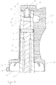
- FIG. 1 is the input shaft 1 of a steering gear, not shown, of a motor vehicle shown.
- the input shaft 1 is drilled hollow in the axial direction.
- the torsion bar 2 passes through the input shaft 1 except for a first end portion 3, and is rotatably connected to it via a transverse pin 4.
- the hollow bore 5 in the first end region 3 is provided for receiving a middle position cap 6.
- the middle position cap 6 assumes, inter alia, the orientation of the input shaft 1 relative to the steering column, not shown.
- the torsion bar is rotatably connected at its protruding end with a pinion by means of a press connection.
- the input shaft is surrounded by a housing approximately from the center to the second end and supported therein in an input shaft bearing.
- the middle position cap 6 has for receiving the input shaft 1 on a longitudinal bore 7, wherein, inter alia, for rotationally fixed engagement of the two components on the inner wall 8 of the longitudinal bore 7 and the outside 9 of the input shaft 1 is partially formed a serrated profile.
- the centering cap 6 surrounds the input shaft 1 essentially up to a peripheral cutout 10 from the middle to the first end 3 '.
- the middle position cap 6 has an expanded inner and outer diameter at the housing-side end 11 for receiving the housing.
- This acting as a protective cap extension 12 includes a housing opening of a housing end with play, so that the lying in the housing input shaft and the input shaft bearing are protected from external influences.
- the centering cap 6 also has a thin-walled extension 13 extending axially from the protective cap 12 to beyond the first end 3 'of the input shaft.
- the extension 13 is designed such that it is clamped in a part of a universal joint of the steering column and thus serves as a positioning aid of the steering column relative to the input shaft.
- a pot-shaped extension 14 is provided at the end of the steering column near the centering cap, which is received in the hollow bore of the first end portion 3.
- the first end 3 'of the input shaft 1 is covered by the middle position cap 6 and the hollow bore 5 is closed by the cup-shaped extension 14.
- the pot-shaped extension 14 has a sealing area, the on the inner wall 15 of the input shaft is present. It is conceivable to form this sealing region as a sealing lip, as an O-ring or as a molded elastomer on the extension 14 of the centering cap 6.
- a circumferential groove 16 in the serration is provided on the outside 9 of the input shaft 1.
- the part of the cutout in the extension 10 'and the groove 16 serve to receive a clamping screw, is clamped by the interaction of a nut part of the universal joint of the steering column with the input shaft.
- the part of the universal joint not shown, has a longitudinal slot into which the thin-walled extension 13 of the input shaft engages in the mounted state.
- This part of the universal joint essentially surrounds the input shaft in the region of the cutout and the serrations.
- the interaction of the clamping screw with the cutout 10 'and the circumferential groove 16 serves as a further assurance of the connection.
- a radially projecting nose 18 is provided on the circumferential casing 17 of the protective cap 12, which serves as a marker. During assembly, this marking must match a second mark provided on the steering gear. This ensures that when engaging the extension of the middle position cap in the longitudinal slot of the universal joint, the steering wheel is in the middle position for straight ahead and thus in correct assignment to the steering gear.
- the middle position cap 6 with protective cap 12, pot-shaped extension 14, thin-walled extension 13 and nose 18 is formed as a one-piece plastic part, which is produced by injection molding.
- the inventive input shaft-Drehstabverbund with middle position cap can be dispensed with the conventionally provided O-ring groove of the torsion bar. This makes the balancing much easier, the torsion bar can be shortened around the ring groove, the life of the Torsion bar is increased and the costs of production are significantly lower.
Landscapes
- Engineering & Computer Science (AREA)
- Chemical & Material Sciences (AREA)
- Combustion & Propulsion (AREA)
- Transportation (AREA)
- Mechanical Engineering (AREA)
- Power Steering Mechanism (AREA)
Description
- Die vorliegende Erfindung betrifft eine Kraftfahrzeuglenkung mit einem Eingangswellen-Drehstabverbund und eine Mittelstellungskappe mit den Merkmalen des Oberbegriffs des Anspruchs 1.
- Bei gattungsgemäßen Zahnstangenlenkgetrieben überträgt eine Lenkwelle das von einem Fahrer auf ein Lenkrad ausgeübte Lenkdrehmoment auf eine Eingangswelle eines Lenkgetriebes. Die Eingangswelle des Lenkgetriebes ist mit einem Ritzel über einen Drehstab verbunden, wobei das Ritzel mit einer Zahnstange kämmt, die in dem Gehäuse des Lenkgetriebes in Längsrichtung verschiebbar gelagert ist. Eine Drehung der Eingangswelle und des Ritzels wird dadurch in eine Schiebebewegung der Zahnstange umgesetzt. Die Zahnstange selbst ist über Spurstangen mit den gelenkten Fahrzeugrädern des Kraftfahrzeugs verbunden. Die Drehung des Lenkrades wird so in eine Lenkbewegung der gelenkten Räder umgesetzt.
- Der Drehstab verbindet die Eingangswelle und das Lenkritzel in axialer Richtung, so dass sie zueinander eine definierte Position haben. Weiterhin bewirkt er in Abhängigkeit vom Lenkradhandmoment eine relative Verdrehung zwischen der Eingangswelle und dem Lenkritzel in einem Lenkventil, die zur Steuerung einer hydraulischen Lenkunterstützung genutzt wird.
- Der Drehstab wird an einem Ende in einer Bohrung des Lenkritzels eingepresst. Am anderen Ende wird er mit der Eingangswelle verbunden. Dazu werden herkömmlicherweise beide quer durchbohrt und verstiftet. Dabei wird die Eingangswelle in eine Position gebracht, von der aus die Lenkventilkennung für beide Drehrichtungen symmetrisch ist, die so genannte hydraulische Mitte. In dieser Position wird die Eingangswelle mit dem unbelasteten und spannungsfreien Drehstab verbunden. Durch diesen Vorgang, das so genannte Balancieren des Ventils, wird sichergestellt, dass ohne ein aufgebrachtes Lenkradmoment, weder Druck in die eine noch in die andere Zylinderkammer eingesteuert wird und dass der Druckaufbau unter Lenkradmomenteneinfluss in beiden Drehrichtungen symmetrisch erfolgt.
- In einer weiteren Ausführungsform wird der Drehstab an einem Ende in einer Bohrung des Lenkritzels eingepresst. Am anderen Ende wird er mit der Eingangswelle verbunden. Dazu werden beide Bauteile drehfest miteinander verbunden. Dies kann sowohl kraftschlüssig als auch formschlüssig erfolgen. Beide Verfahren können auch in Kombination zum Einsatz kommen. Dabei wird die Eingangswelle in eine Position gebracht, von der aus die Lenkventilkennung für beide Drehrichtungen symmetrisch ist, die so genannte hydraulische Mitte. In dieser Position wird die Eingangswelle mit dem unbelasteten und spannungsfreien Drehstab verbunden. Durch diesen Vorgang, das so genannte Balancieren des Ventils, wird sichergestellt, dass ohne ein aufgebrachtes Lenkradmoment, weder Druck in die eine noch in die andere Zylinderkammer eingesteuert wird und dass der Druckaufbau unter Lenkradmomenteneinfluss in beiden Drehrichtungen symmetrisch erfolgt.
- Zur Aufnahme des Drehstabs ist die Eingangswelle hohl gebohrt. Der Drehstab durchsetzt die Eingangswelle und wird von ihr überragt. Dieses überragende Ende der Eingangswelle wird von einer Mittelstellungskappe umfangsseitig umgeben. Die Mittelstellungskappe dient zum Einen als Schutzkappe für die darunter liegenden Bauteile und zum andern als Positionierungshilfe für das Zusammenfügen der Eingangswelle mit der Lenksäule.
- Nach außen ist der Hohlraum der Eingangswelle durch einen O-Ring zwischen Eingangswelle und Drehstab abgedichtet. Damit der O-Ring richtig positioniert werden kann, besitzt der Drehstab eine Nut zur Aufnahme des O-Rings. Dazu muss der Drehstab an seinem einen Ende länger ausgeführt werden als es seitens des Pressverbandes mit der Eingangswelle notwendig ist. Das Einbringen der O-Ring Nut ist zudem recht teuer und bildet zugleich eine Schwachstelle (Sollbruchstelle) im Bauteil. Weiterhin wird das Balancieren durch die Reibung des O-Rings an der Innenseite der Eingangswelle erschwert.
- Aus der Offenlegungsschrift
DE 10 2011 017 150 A1 ist eine Kraftfahrzeuglenkung bekannt, bei der die Abdichtung der Verbindung von Drehstab und Welle durch eine Presspassung erzielt wird. Eine Abdichtung der Eingangswelle aus Richtung der Lenksäule ist nicht gegeben. - Die
DE 41 29 042 A1 offenbart eine Schutzkappe, die nur bei richtiger Positionierung der Eingangswelle relativ zur Lenksäule die Bohrung der Sicherungsschraube freigibt und somit eine Positionierungshilfe darstellt. Eine Abdichtung des Eingangswellen-Drehstabverbunds ist nicht gegeben.DE 41 29 042 offenbart den Oberbegriff des Anspruchs 1. - Es ist Aufgabe der vorliegenden Erfindung, eine Kraftfahrzeuglenkung mit einem Eingangswellen-Drehstabverbund mit Mittelstellungskappe und eine Mittelstellungskappe anzugeben, die besonders kostengünstig herzustellen sind, ohne dass sich die Dauerhaltbarkeit des Verbundes verringert.
- Diese Aufgabe wird von einer Kraftfahrzeuglenkung mit einem Eingangswellen-Drehstabverbund mit den Merkmalen des Anspruchs 1 und einer Mittelstellungskappe mit den Merkmalen des Anspruchs 10 gelöst.
- Danach ist eine Kraftfahrzeuglenkung mit einem Eingangswellen-Drehstabverbund, aufweisend einen in einer axialen Hohlbohrung einer Eingangswelle angeordneten Drehstab, wobei der Drehstab in einem ersten Endbereich mit der Eingangswelle drehfest verbunden ist, und eine die Eingangswelle zumindest teilweise umgebenden Mittelstellungskappe, die einen in Axialrichtung erstreckenden Fortsatz aufweist, der zur Ausrichtung der Eingangswelle relativ zu einer Lenksäule angeordnet ist, vorgesehen, bei der die Mittelstellungskappe in die Hohlbohrung der Eingangswelle an einem lenksäulennahen Ende eingreift. Durch diese Ausgestaltung der Mittelstellungskappe kann auf die herkömmlich vorgesehene Abdichtung zwischen dem Drehstab und der Eingangswelle verzichtet werden. Dies hat den Vorteil, dass der Drehstab ohne Nut gefertigt werden kann, wodurch Kosten eingespart werden und das Bauteil langlebiger wird. Weiterhin ist das Balancieren deutlich einfacher, da auf den O-Ring zwischen Drehstab und Eingangswelle verzichtet wird.
- Vorzugsweise ist zwischen der Mittelstellungskappe und einer Innenwandung der Hohlbohrung der Eingangswelle ein Dichtbereich vorgesehen. Dieser Dichtbereich dient als zusätzliche Abdichtung der Eingangswelle aus Richtung der Lenksäule.
- Bevorzugt weist der Dichtbereich wenigstens eine Dichtlippe auf.
- In einer vorteilhaften Ausgestaltung wird die Mittelstellungskappe einstückig in einem Spritzgussverfahren hergestellt. Dabei kann bevorzugt vorgesehen sein, dass die Mittelstellungskappe mit dem Dichtbereich im Zweikomponenten-Spritzgussverfahren hergestellt wird.
- Vorteilhafterweise weist die Mittelstellungskappe einen topfförmigen Fortsatz zur Aufnahme in die Hohlbohrung der Eingangswelle auf.
- In einer Ausführungsform weist der topfförmige Fortsatz eine umlaufende Außennut zur Aufnahme eines O-Rings auf. Dieser O-Ring dient als Abdichtung bzw. Dichtbereich zwischen der Mittelstellungskappe und der Innenwandung der Hohlbohrung der Eingangswelle.
- Zudem ist es vorteilhaft, wenn die Eingangswelle den Drehstab über den ersten Endbereich überragt.
- Bevorzugt ist der Drehstab in dem ersten Endbereich mit der Eingangswelle drehfest verstiftet.
- Weiterhin ist es vorteilhaft, wenn die Mittelstellungskappe am lenksäulenfernen Ende in eine Schutzkappe ausläuft, die eine darunterliegende Gehäuseöffnung eines die Eingangswelle umgebenden Gehäuses abdeckt.
- Es ist zudem eine Mittelstellungskappe für eine Kraftfahrzeuglenkung mit wenigstens einem der vorhergehenden Merkmale vorgesehen.
- Eine bevorzugte Ausführungsform der Erfindung wird nachfolgend anhand der Zeichnung näher erläutert. Es zeigt:
- Fig. 1:
- einen Längsschnitt eines Eingangswellen-Drehstabverbundes mit einer Mittelstellungskappe.
- In der
Figur 1 ist die Eingangswelle 1 eines nicht näher dargestellten Lenkgetriebes eines Kraftfahrzeugs dargestellt. Zur Aufnahme eines Drehstabs 2 ist die Eingangswelle 1 in Axialrichtung hohl gebohrt. Der Drehstab 2 durchsetzt die Eingangswelle 1 bis auf einen ersten Endbereich 3, und ist mit ihr über einen Querstift 4 drehfest verbunden. Die Hohlbohrung 5 im ersten Endbereich 3 ist zur Aufnahme einer Mittelstellungskappe 6 vorgesehen. Die Mittelstellungskappe 6 übernimmt unter anderem die Ausrichtung der Eingangswelle 1 relativ zur nicht dargestellten Lenksäule. In der Zeichnung ist weiterhin nicht dargestellt, dass an einem, dem ersten gegenüberliegenden zweiten Ende der Eingangswelle, diese von dem Drehstab überragt wird. Der Drehstab ist dabei an seinem überragenden Ende drehfest mit einem Ritzel mittels einer Pressverbindung verbunden. Die Eingangswelle ist in etwa von der Mitte ab bis zum zweiten Ende von einem Gehäuse umgeben und darin in einem Eingangswellenlager gelagert. - Die Mittelstellungskappe 6 weist zur Aufnahme der Eingangswelle 1 eine Längsbohrung 7 auf, wobei unter anderem zum drehfesten Ineinandergreifen der beiden Bauteile auf der Innenwandung 8 der Längsbohrung 7 und der Außenseite 9 der Eingangswelle 1 teilweise ein Kerbzahnprofil ausgebildet ist. Im Montagezustand umgibt die Mittelstellungskappe 6 die Eingangswelle 1 im Wesentlichen bis auf einen umfangsseitigen Ausschnitt 10 von der Mitte bis zum ersten Ende 3'. Dabei weist die Mittelstellungskappe 6 einen erweiterten Innen- und Außendurchmesser am gehäusenahen Ende 11 zur Aufnahme des Gehäuses auf. Diese als Schutzkappe wirkende Erweiterung 12 umfasst eine Gehäuseöffnung eines Gehäuseendes mit Spiel, so dass die im Gehäuse liegende Eingangswelle und das Eingangswellenlager vor äußeren Einflüssen geschützt sind. Die Mittelstellungskappe 6 weist weiterhin einen sich axial von der Schutzkappe 12 bis über das erste Ende 3' der Eingangswelle hinaus erstreckenden dünnwandigen Fortsatz 13 auf. Der Fortsatz 13 ist so ausgestaltet, dass er in einem Teil eines Kreuzgelenks der Lenksäule verklemmt wird und somit als Positionierungshilfe der Lenksäule relativ zur Eingangswelle dient. Weiterhin ist am lenksäulennahen Ende der Mittelstellungskappe ein topfförmig ausgestalteter Fortsatz 14 vorgesehen, der in die Hohlbohrung des ersten Endbereichs 3 aufgenommen ist. Somit wird das erste Ende 3' der Eingangswelle 1 von der Mittelstellungskappe 6 abgedeckt und die Hohlbohrung 5 von dem topfförmigen Fortsatz 14 verschlossen. Vorzugsweise besitzt der topfförmige Fortsatz 14 einen Dichtbereich, der an der Innenwandung 15 der Eingangswelle anliegt. Es ist denkbar diesen Dichtbereich als Dichtlippen, als O-Ring oder als angespritztes Elastomer auf dem Fortsatz 14 der Mittelstellungskappe 6 auszubilden.
- Im Bereich des Ausschnitts 10 der Mittelstellungskappe 6 ist dabei auf der Außenseite 9 der Eingangswelle 1 eine umlaufende Nut 16 in der Kerbverzahnung vorgesehen. Der Teil des Ausschnitts im Fortsatz 10' und die Nut 16 dienen zur Aufnahme einer Klemmschraube, durch die im Zusammenspiel mit einer Mutter der Teil des Kreuzgelenks der Lenksäule mit der Eingangswelle verklemmt wird. Dazu weist der nicht dargestellte Teil des Kreuzgelenks einen Längsschlitz auf, in den im montierten Zustand der dünnwandige Fortsatz 13 der Eingangswelle eingreift. Dieser Teil des Kreuzgelenks umgibt die Eingangswelle im Bereich des Ausschnitts und der Kerbverzahnung im Wesentlichen unmittelbar. Durch die Klemmverbindung werden das Teil des Kreuzgelenks und die Eingangswelle reibschlüssig verbunden. Das Zusammenspiel der Klemmschraube mit dem Ausschnitt 10' und der umlaufenden Nut 16 dient als weitere Sicherung der Verbindung.
- Weiterhin ist an dem Umfangsmantel 17 der Schutzkappe 12 eine radial abstehende Nase 18 vorgesehen, die als Markierung dient. Bei der Montage muss diese Markierung mit einer zweiten Markierung, die am Lenkgetriebe vorgesehen ist, übereinstimmen. Dadurch ist gewährleistet, dass beim Eingreifen des Fortsatzes der Mittelstellungskappe in den Längsschlitz des Kreuzgelenks sich das Lenkrad in Mittelstellung für die Geradeausfahrt und damit in korrekter Zuordnung zum Lenkgetriebe befindet.
- Die Mittelstellungskappe 6 mit Schutzkappe 12, topfförmigen Fortsatz 14, dünnwandigen Fortsatz 13 und Nase 18 ist als ein einstückiges Kunststoffteil ausgebildet, welches im Spritzgießverfahren hergestellt ist.
- Durch den erfindungsgemäßen Eingangswellen-Drehstabverbund mit Mittelstellungskappe kann auf die herkömmlich vorgesehene O-Ring-Nut des Drehstabs verzichtet werden. Dadurch wird das Balancieren deutlich einfacher, der Drehstab kann um die Ringnut verkürzt werden, die Lebensdauer des Drehstabs wird erhöht und die Kosten für die Fertigung fallen deutlich geringer aus.
Claims (13)
- Kraftfahrzeuglenkung mit einem Eingangswellen-Drehstabverbund aufweisend einen in einer axialen Hohlbohrung (5) einer Eingangswelle (1) angeordneten Drehstab (2), wobei der Drehstab in einem ersten Endbereich mit der Eingangswelle drehfest verbunden ist, und eine die Eingangswelle (1) zumindest teilweise umgebenden Mittelstellungskappe (6), die einen in Axialrichtung erstreckenden Fortsatz (13) aufweist, der zur Ausrichtung der Eingangswelle (1) relativ zu einer Lenksäule vorgesehen ist, dadurch gekennzeichnet, dass die Mittelstellungskappe (6) in die Hohlbohrung (5) der Eingangswelle (1) an einem lenksäulennahen Ende (3') eingreift.
- Kraftfahrzeuglenkung nach Anspruch 1, dadurch gekennzeichnet, dass zwischen der Mittelstellungskappe (6) und einer Innenwandung (15) der Hohlbohrung (5) der Eingangswelle (1) ein Dichtbereich vorgesehen ist.
- Kraftfahrzeuglenkung nach Anspruch 2, dadurch gekennzeichnet, dass der Dichtbereich wenigstens eine Dichtlippe aufweist.
- Kraftfahrzeuglenkung nach einem der vorhergehenden Ansprüche, dadurch gekennzeichnet, dass die Mittelstellungskappe (6) einstückig in einem Spritzgussverfahren hergestellt ist.
- Kraftfahrzeuglenkung nach einem der vorhergehenden Ansprüche, dadurch gekennzeichnet, dass die Mittelstellungskappe (6) einen topfförmigen Fortsatz (14) zur Aufnahme in die Hohlbohrung (5) der Eingangswelle (1) aufweist.
- Kraftfahrzeuglenkung nach Anspruch 5, dadurch gekennzeichnet, dass der topfförmige Fortsatz (14) eine umlaufende Außennut zur Aufnahme eines O-Rings aufweist.
- Kraftfahrzeuglenkung nach einem der vorhergehenden Ansprüche, dadurch gekennzeichnet, dass die Eingangswelle (1) den Drehstab (2) über den ersten Endbereich (3) überragt.
- Kraftfahrzeuglenkung nach einem der vorhergehenden Ansprüche, dadurch gekennzeichnet, dass der Drehstab (2) in dem ersten Endbereich mit der Eingangswelle (1) drehfest verstiftet ist.
- Kraftfahrzeuglenkung nach einem der vorhergehenden Ansprüche, dadurch gekennzeichnet, dass der Drehstab (2) in dem ersten Endbereich mit der Eingangswelle (1) drehfest verbunden ist
- Kraftfahrzeuglenkung nach Anspruch 9, dadurch gekennzeichnet, dass der Drehstab (2) in dem ersten Endbereich mit der Eingangswelle (1) formschlüssig verbunden ist.
- Kraftfahrzeuglenkung nach Anspruch 9, dadurch gekennzeichnet, dass der Drehstab (2) in dem ersten Endbereich mit der Eingangswelle (1) kraftschlüssig verbunden ist.
- Kraftfahrzeuglenkung nach einem der vorhergehenden Ansprüche, dadurch gekennzeichnet, dass die Mittelstellungskappe (6) am lenksäulenfernen Ende in eine Schutzkappe (12) ausläuft, die eine darunterliegende Gehäuseöffnung eines die Eingangswelle umgebenden Gehäuses abdeckt.
- Mittelstellungskappe (6) für eine Kraftfahrzeuglenkung nach einem der vorhergehenden Ansprüche.
Applications Claiming Priority (2)
| Application Number | Priority Date | Filing Date | Title |
|---|---|---|---|
| DE102014007503.6A DE102014007503B4 (de) | 2014-05-23 | 2014-05-23 | Montagehilfe |
| PCT/EP2015/058568 WO2015176894A1 (de) | 2014-05-23 | 2015-04-21 | Mittelstellungskappe zur montagehilfe des eingangswelle-drehstabverbunds einer kraftfahrzeuglenkung |
Publications (2)
| Publication Number | Publication Date |
|---|---|
| EP3145791A1 EP3145791A1 (de) | 2017-03-29 |
| EP3145791B1 true EP3145791B1 (de) | 2019-06-05 |
Family
ID=52998139
Family Applications (1)
| Application Number | Title | Priority Date | Filing Date |
|---|---|---|---|
| EP15718204.9A Active EP3145791B1 (de) | 2014-05-23 | 2015-04-21 | Mittelstellungskappe zur montagehilfe des eingangswelle-drehstabverbunds einer kraftfahrzeuglenkung |
Country Status (3)
| Country | Link |
|---|---|
| EP (1) | EP3145791B1 (de) |
| DE (1) | DE102014007503B4 (de) |
| WO (1) | WO2015176894A1 (de) |
Families Citing this family (1)
| Publication number | Priority date | Publication date | Assignee | Title |
|---|---|---|---|---|
| JP2022143667A (ja) * | 2021-03-18 | 2022-10-03 | 本田技研工業株式会社 | 車両用ステアリング装置及びその組立方法 |
Family Cites Families (4)
| Publication number | Priority date | Publication date | Assignee | Title |
|---|---|---|---|---|
| DE4129042C2 (de) | 1991-08-31 | 1995-06-14 | Bayerische Motoren Werke Ag | Sicherungsvorrichtung zur lagegenauen Verbindung einer Klemmhülse mit einer Getriebewelle |
| DE102011017150A1 (de) | 2011-04-15 | 2012-10-18 | Volkswagen Aktiengesellschaft | Welle-Nabe-Verbindung und Lenksäule mit einer solchen |
| JP5796410B2 (ja) * | 2011-08-24 | 2015-10-21 | 株式会社ジェイテクト | 連結構造及びステアリング装置 |
| US20140020487A1 (en) * | 2012-07-19 | 2014-01-23 | ZF Steering Systems, LLC | Axially located bolt guide cap |
-
2014
- 2014-05-23 DE DE102014007503.6A patent/DE102014007503B4/de not_active Expired - Fee Related
-
2015
- 2015-04-21 WO PCT/EP2015/058568 patent/WO2015176894A1/de not_active Ceased
- 2015-04-21 EP EP15718204.9A patent/EP3145791B1/de active Active
Non-Patent Citations (1)
| Title |
|---|
| None * |
Also Published As
| Publication number | Publication date |
|---|---|
| DE102014007503A1 (de) | 2015-11-26 |
| WO2015176894A1 (de) | 2015-11-26 |
| EP3145791A1 (de) | 2017-03-29 |
| DE102014007503B4 (de) | 2019-03-14 |
Similar Documents
| Publication | Publication Date | Title |
|---|---|---|
| DE102014206934B4 (de) | Stellmotor | |
| EP1429951A1 (de) | Zahnstangen-lenkeinrichtung | |
| EP2093127B1 (de) | Lenkgetriebe mit Sensor | |
| EP0751059B1 (de) | Verfahren und Vorrichtung zur Montage eines Servoventils | |
| WO2015113534A1 (de) | Nockenwellenverstärker | |
| DE102018202318B4 (de) | Lenksensorvorrichtung mit Steck-Drehverbindung | |
| DE102016207868A1 (de) | Montagemodul für eine Fahrzeugleuchte | |
| EP3538420B1 (de) | Zahnstangenlenkung für ein kraftfahrzeug mit schneckengetriebe | |
| WO2016206864A1 (de) | Anordnung zur abdichtung eines aktuators und adapterring zur abdichtung | |
| EP3313675B1 (de) | Reifendruckkontrollsystem für ein fahrzeug | |
| DE102014007503B4 (de) | Montagehilfe | |
| EP3649038B1 (de) | Verstelleinrichtung für ein fahrwerk eines kraftfahrzeuges sowie hinterachslenkung | |
| DE102009019189A1 (de) | Verschluss-Schraubverbindung, Zahnstangenlenkung und Verfahren zum Einstellen eines Druckstücks einer Zahnstangenlenkung | |
| DE10254688B3 (de) | Hydraulische Servolenkung für Kraftfahrzeuge | |
| EP3572312B1 (de) | Zentrierelement und steuereinrichtung für ein fahrrad | |
| DE102009038232A1 (de) | Servolenkung | |
| WO2019029909A1 (de) | Radaufhängung | |
| EP3804096B1 (de) | Elektromechanische kraftfahrzeuglenkung aufweisend mittels eines kegelförmigen pressverbands verbundene gehäuseteile | |
| DE10224344A1 (de) | Verfahren zum Verbinden eines Drehstabes | |
| DE102008040705A1 (de) | Scheibenwischerantrieb | |
| EP3227166B1 (de) | Servolenkung für fahrzeuge | |
| WO2017025429A1 (de) | Klemmvorrichtung einer verstellbaren lenksäule für kraftfahrzeuge | |
| DE102011084401A1 (de) | Planetenwälzgewindetrieb | |
| DE102018220074A1 (de) | Lenkgetriebe und Verfahren zur Montage eines solchen Lenkgetriebes | |
| DE102006031709A1 (de) | Fahrzeugrad |
Legal Events
| Date | Code | Title | Description |
|---|---|---|---|
| STAA | Information on the status of an ep patent application or granted ep patent |
Free format text: STATUS: THE INTERNATIONAL PUBLICATION HAS BEEN MADE |
|
| PUAI | Public reference made under article 153(3) epc to a published international application that has entered the european phase |
Free format text: ORIGINAL CODE: 0009012 |
|
| STAA | Information on the status of an ep patent application or granted ep patent |
Free format text: STATUS: REQUEST FOR EXAMINATION WAS MADE |
|
| 17P | Request for examination filed |
Effective date: 20161111 |
|
| AK | Designated contracting states |
Kind code of ref document: A1 Designated state(s): AL AT BE BG CH CY CZ DE DK EE ES FI FR GB GR HR HU IE IS IT LI LT LU LV MC MK MT NL NO PL PT RO RS SE SI SK SM TR |
|
| AX | Request for extension of the european patent |
Extension state: BA ME |
|
| RAP1 | Party data changed (applicant data changed or rights of an application transferred) |
Owner name: THYSSENKRUPP PRESTA AG Owner name: THYSSENKRUPP AG |
|
| DAV | Request for validation of the european patent (deleted) | ||
| DAX | Request for extension of the european patent (deleted) | ||
| GRAP | Despatch of communication of intention to grant a patent |
Free format text: ORIGINAL CODE: EPIDOSNIGR1 |
|
| STAA | Information on the status of an ep patent application or granted ep patent |
Free format text: STATUS: GRANT OF PATENT IS INTENDED |
|
| INTG | Intention to grant announced |
Effective date: 20190108 |
|
| INTG | Intention to grant announced |
Effective date: 20190108 |
|
| GRAS | Grant fee paid |
Free format text: ORIGINAL CODE: EPIDOSNIGR3 |
|
| GRAA | (expected) grant |
Free format text: ORIGINAL CODE: 0009210 |
|
| STAA | Information on the status of an ep patent application or granted ep patent |
Free format text: STATUS: THE PATENT HAS BEEN GRANTED |
|
| AK | Designated contracting states |
Kind code of ref document: B1 Designated state(s): AL AT BE BG CH CY CZ DE DK EE ES FI FR GB GR HR HU IE IS IT LI LT LU LV MC MK MT NL NO PL PT RO RS SE SI SK SM TR |
|
| REG | Reference to a national code |
Ref country code: GB Ref legal event code: FG4D Free format text: NOT ENGLISH |
|
| REG | Reference to a national code |
Ref country code: CH Ref legal event code: EP |
|
| REG | Reference to a national code |
Ref country code: AT Ref legal event code: REF Ref document number: 1139700 Country of ref document: AT Kind code of ref document: T Effective date: 20190615 |
|
| REG | Reference to a national code |
Ref country code: IE Ref legal event code: FG4D Free format text: LANGUAGE OF EP DOCUMENT: GERMAN |
|
| REG | Reference to a national code |
Ref country code: DE Ref legal event code: R096 Ref document number: 502015009235 Country of ref document: DE |
|
| REG | Reference to a national code |
Ref country code: NL Ref legal event code: MP Effective date: 20190605 |
|
| REG | Reference to a national code |
Ref country code: LT Ref legal event code: MG4D |
|
| PG25 | Lapsed in a contracting state [announced via postgrant information from national office to epo] |
Ref country code: FI Free format text: LAPSE BECAUSE OF FAILURE TO SUBMIT A TRANSLATION OF THE DESCRIPTION OR TO PAY THE FEE WITHIN THE PRESCRIBED TIME-LIMIT Effective date: 20190605 Ref country code: AL Free format text: LAPSE BECAUSE OF FAILURE TO SUBMIT A TRANSLATION OF THE DESCRIPTION OR TO PAY THE FEE WITHIN THE PRESCRIBED TIME-LIMIT Effective date: 20190605 Ref country code: NO Free format text: LAPSE BECAUSE OF FAILURE TO SUBMIT A TRANSLATION OF THE DESCRIPTION OR TO PAY THE FEE WITHIN THE PRESCRIBED TIME-LIMIT Effective date: 20190905 Ref country code: HR Free format text: LAPSE BECAUSE OF FAILURE TO SUBMIT A TRANSLATION OF THE DESCRIPTION OR TO PAY THE FEE WITHIN THE PRESCRIBED TIME-LIMIT Effective date: 20190605 Ref country code: SE Free format text: LAPSE BECAUSE OF FAILURE TO SUBMIT A TRANSLATION OF THE DESCRIPTION OR TO PAY THE FEE WITHIN THE PRESCRIBED TIME-LIMIT Effective date: 20190605 Ref country code: LT Free format text: LAPSE BECAUSE OF FAILURE TO SUBMIT A TRANSLATION OF THE DESCRIPTION OR TO PAY THE FEE WITHIN THE PRESCRIBED TIME-LIMIT Effective date: 20190605 Ref country code: ES Free format text: LAPSE BECAUSE OF FAILURE TO SUBMIT A TRANSLATION OF THE DESCRIPTION OR TO PAY THE FEE WITHIN THE PRESCRIBED TIME-LIMIT Effective date: 20190605 |
|
| PG25 | Lapsed in a contracting state [announced via postgrant information from national office to epo] |
Ref country code: LV Free format text: LAPSE BECAUSE OF FAILURE TO SUBMIT A TRANSLATION OF THE DESCRIPTION OR TO PAY THE FEE WITHIN THE PRESCRIBED TIME-LIMIT Effective date: 20190605 Ref country code: RS Free format text: LAPSE BECAUSE OF FAILURE TO SUBMIT A TRANSLATION OF THE DESCRIPTION OR TO PAY THE FEE WITHIN THE PRESCRIBED TIME-LIMIT Effective date: 20190605 Ref country code: BG Free format text: LAPSE BECAUSE OF FAILURE TO SUBMIT A TRANSLATION OF THE DESCRIPTION OR TO PAY THE FEE WITHIN THE PRESCRIBED TIME-LIMIT Effective date: 20190905 Ref country code: GR Free format text: LAPSE BECAUSE OF FAILURE TO SUBMIT A TRANSLATION OF THE DESCRIPTION OR TO PAY THE FEE WITHIN THE PRESCRIBED TIME-LIMIT Effective date: 20190906 |
|
| PG25 | Lapsed in a contracting state [announced via postgrant information from national office to epo] |
Ref country code: PT Free format text: LAPSE BECAUSE OF FAILURE TO SUBMIT A TRANSLATION OF THE DESCRIPTION OR TO PAY THE FEE WITHIN THE PRESCRIBED TIME-LIMIT Effective date: 20191007 Ref country code: SK Free format text: LAPSE BECAUSE OF FAILURE TO SUBMIT A TRANSLATION OF THE DESCRIPTION OR TO PAY THE FEE WITHIN THE PRESCRIBED TIME-LIMIT Effective date: 20190605 Ref country code: EE Free format text: LAPSE BECAUSE OF FAILURE TO SUBMIT A TRANSLATION OF THE DESCRIPTION OR TO PAY THE FEE WITHIN THE PRESCRIBED TIME-LIMIT Effective date: 20190605 Ref country code: NL Free format text: LAPSE BECAUSE OF FAILURE TO SUBMIT A TRANSLATION OF THE DESCRIPTION OR TO PAY THE FEE WITHIN THE PRESCRIBED TIME-LIMIT Effective date: 20190605 Ref country code: RO Free format text: LAPSE BECAUSE OF FAILURE TO SUBMIT A TRANSLATION OF THE DESCRIPTION OR TO PAY THE FEE WITHIN THE PRESCRIBED TIME-LIMIT Effective date: 20190605 Ref country code: CZ Free format text: LAPSE BECAUSE OF FAILURE TO SUBMIT A TRANSLATION OF THE DESCRIPTION OR TO PAY THE FEE WITHIN THE PRESCRIBED TIME-LIMIT Effective date: 20190605 |
|
| PG25 | Lapsed in a contracting state [announced via postgrant information from national office to epo] |
Ref country code: IT Free format text: LAPSE BECAUSE OF FAILURE TO SUBMIT A TRANSLATION OF THE DESCRIPTION OR TO PAY THE FEE WITHIN THE PRESCRIBED TIME-LIMIT Effective date: 20190605 Ref country code: IS Free format text: LAPSE BECAUSE OF FAILURE TO SUBMIT A TRANSLATION OF THE DESCRIPTION OR TO PAY THE FEE WITHIN THE PRESCRIBED TIME-LIMIT Effective date: 20191005 Ref country code: SM Free format text: LAPSE BECAUSE OF FAILURE TO SUBMIT A TRANSLATION OF THE DESCRIPTION OR TO PAY THE FEE WITHIN THE PRESCRIBED TIME-LIMIT Effective date: 20190605 |
|
| REG | Reference to a national code |
Ref country code: DE Ref legal event code: R097 Ref document number: 502015009235 Country of ref document: DE |
|
| PG25 | Lapsed in a contracting state [announced via postgrant information from national office to epo] |
Ref country code: TR Free format text: LAPSE BECAUSE OF FAILURE TO SUBMIT A TRANSLATION OF THE DESCRIPTION OR TO PAY THE FEE WITHIN THE PRESCRIBED TIME-LIMIT Effective date: 20190605 |
|
| PLBE | No opposition filed within time limit |
Free format text: ORIGINAL CODE: 0009261 |
|
| STAA | Information on the status of an ep patent application or granted ep patent |
Free format text: STATUS: NO OPPOSITION FILED WITHIN TIME LIMIT |
|
| PG25 | Lapsed in a contracting state [announced via postgrant information from national office to epo] |
Ref country code: PL Free format text: LAPSE BECAUSE OF FAILURE TO SUBMIT A TRANSLATION OF THE DESCRIPTION OR TO PAY THE FEE WITHIN THE PRESCRIBED TIME-LIMIT Effective date: 20190605 Ref country code: DK Free format text: LAPSE BECAUSE OF FAILURE TO SUBMIT A TRANSLATION OF THE DESCRIPTION OR TO PAY THE FEE WITHIN THE PRESCRIBED TIME-LIMIT Effective date: 20190605 |
|
| 26N | No opposition filed |
Effective date: 20200306 |
|
| PG25 | Lapsed in a contracting state [announced via postgrant information from national office to epo] |
Ref country code: SI Free format text: LAPSE BECAUSE OF FAILURE TO SUBMIT A TRANSLATION OF THE DESCRIPTION OR TO PAY THE FEE WITHIN THE PRESCRIBED TIME-LIMIT Effective date: 20190605 |
|
| PG25 | Lapsed in a contracting state [announced via postgrant information from national office to epo] |
Ref country code: MC Free format text: LAPSE BECAUSE OF FAILURE TO SUBMIT A TRANSLATION OF THE DESCRIPTION OR TO PAY THE FEE WITHIN THE PRESCRIBED TIME-LIMIT Effective date: 20190605 |
|
| REG | Reference to a national code |
Ref country code: CH Ref legal event code: PL |
|
| PG25 | Lapsed in a contracting state [announced via postgrant information from national office to epo] |
Ref country code: LU Free format text: LAPSE BECAUSE OF NON-PAYMENT OF DUE FEES Effective date: 20200421 Ref country code: CH Free format text: LAPSE BECAUSE OF NON-PAYMENT OF DUE FEES Effective date: 20200430 Ref country code: LI Free format text: LAPSE BECAUSE OF NON-PAYMENT OF DUE FEES Effective date: 20200430 |
|
| REG | Reference to a national code |
Ref country code: BE Ref legal event code: MM Effective date: 20200430 |
|
| PG25 | Lapsed in a contracting state [announced via postgrant information from national office to epo] |
Ref country code: BE Free format text: LAPSE BECAUSE OF NON-PAYMENT OF DUE FEES Effective date: 20200430 |
|
| GBPC | Gb: european patent ceased through non-payment of renewal fee |
Effective date: 20200421 |
|
| PG25 | Lapsed in a contracting state [announced via postgrant information from national office to epo] |
Ref country code: IE Free format text: LAPSE BECAUSE OF NON-PAYMENT OF DUE FEES Effective date: 20200421 Ref country code: GB Free format text: LAPSE BECAUSE OF NON-PAYMENT OF DUE FEES Effective date: 20200421 |
|
| REG | Reference to a national code |
Ref country code: AT Ref legal event code: MM01 Ref document number: 1139700 Country of ref document: AT Kind code of ref document: T Effective date: 20200421 |
|
| PG25 | Lapsed in a contracting state [announced via postgrant information from national office to epo] |
Ref country code: AT Free format text: LAPSE BECAUSE OF NON-PAYMENT OF DUE FEES Effective date: 20200421 |
|
| REG | Reference to a national code |
Ref country code: DE Ref legal event code: R081 Ref document number: 502015009235 Country of ref document: DE Owner name: THYSSENKRUPP PRESTA AKTIENGESELLSCHAFT, LI Free format text: FORMER OWNERS: THYSSENKRUPP AG, 45143 ESSEN, DE; THYSSENKRUPP PRESTA AG, ESCHEN, LI Ref country code: DE Ref legal event code: R081 Ref document number: 502015009235 Country of ref document: DE Owner name: THYSSENKRUPP AG, DE Free format text: FORMER OWNERS: THYSSENKRUPP AG, 45143 ESSEN, DE; THYSSENKRUPP PRESTA AG, ESCHEN, LI |
|
| PG25 | Lapsed in a contracting state [announced via postgrant information from national office to epo] |
Ref country code: MT Free format text: LAPSE BECAUSE OF FAILURE TO SUBMIT A TRANSLATION OF THE DESCRIPTION OR TO PAY THE FEE WITHIN THE PRESCRIBED TIME-LIMIT Effective date: 20190605 Ref country code: CY Free format text: LAPSE BECAUSE OF FAILURE TO SUBMIT A TRANSLATION OF THE DESCRIPTION OR TO PAY THE FEE WITHIN THE PRESCRIBED TIME-LIMIT Effective date: 20190605 |
|
| PG25 | Lapsed in a contracting state [announced via postgrant information from national office to epo] |
Ref country code: MK Free format text: LAPSE BECAUSE OF FAILURE TO SUBMIT A TRANSLATION OF THE DESCRIPTION OR TO PAY THE FEE WITHIN THE PRESCRIBED TIME-LIMIT Effective date: 20190605 |
|
| REG | Reference to a national code |
Ref country code: DE Ref legal event code: R084 Ref document number: 502015009235 Country of ref document: DE |
|
| PGFP | Annual fee paid to national office [announced via postgrant information from national office to epo] |
Ref country code: DE Payment date: 20250422 Year of fee payment: 11 |
|
| PGFP | Annual fee paid to national office [announced via postgrant information from national office to epo] |
Ref country code: FR Payment date: 20250425 Year of fee payment: 11 |