EP3145644B1 - Vorrichung und verfahren zur abfalltrennung - Google Patents
Vorrichung und verfahren zur abfalltrennung Download PDFInfo
- Publication number
- EP3145644B1 EP3145644B1 EP15734425.0A EP15734425A EP3145644B1 EP 3145644 B1 EP3145644 B1 EP 3145644B1 EP 15734425 A EP15734425 A EP 15734425A EP 3145644 B1 EP3145644 B1 EP 3145644B1
- Authority
- EP
- European Patent Office
- Prior art keywords
- waste
- wastes
- orifices
- fraction
- separation
- Prior art date
- Legal status (The legal status is an assumption and is not a legal conclusion. Google has not performed a legal analysis and makes no representation as to the accuracy of the status listed.)
- Active
Links
Images

Classifications
-
- B—PERFORMING OPERATIONS; TRANSPORTING
- B03—SEPARATION OF SOLID MATERIALS USING LIQUIDS OR USING PNEUMATIC TABLES OR JIGS; MAGNETIC OR ELECTROSTATIC SEPARATION OF SOLID MATERIALS FROM SOLID MATERIALS OR FLUIDS; SEPARATION BY HIGH-VOLTAGE ELECTRIC FIELDS
- B03B—SEPARATING SOLID MATERIALS USING LIQUIDS OR USING PNEUMATIC TABLES OR JIGS
- B03B9/00—General arrangement of separating plant, e.g. flow sheets
- B03B9/06—General arrangement of separating plant, e.g. flow sheets specially adapted for refuse
-
- B—PERFORMING OPERATIONS; TRANSPORTING
- B07—SEPARATING SOLIDS FROM SOLIDS; SORTING
- B07B—SEPARATING SOLIDS FROM SOLIDS BY SIEVING, SCREENING, SIFTING OR BY USING GAS CURRENTS; SEPARATING BY OTHER DRY METHODS APPLICABLE TO BULK MATERIAL, e.g. LOOSE ARTICLES FIT TO BE HANDLED LIKE BULK MATERIAL
- B07B1/00—Sieving, screening, sifting, or sorting solid materials using networks, gratings, grids, or the like
- B07B1/18—Drum screens
- B07B1/22—Revolving drums
- B07B1/24—Revolving drums with fixed or moving interior agitators
-
- B—PERFORMING OPERATIONS; TRANSPORTING
- B07—SEPARATING SOLIDS FROM SOLIDS; SORTING
- B07B—SEPARATING SOLIDS FROM SOLIDS BY SIEVING, SCREENING, SIFTING OR BY USING GAS CURRENTS; SEPARATING BY OTHER DRY METHODS APPLICABLE TO BULK MATERIAL, e.g. LOOSE ARTICLES FIT TO BE HANDLED LIKE BULK MATERIAL
- B07B1/00—Sieving, screening, sifting, or sorting solid materials using networks, gratings, grids, or the like
- B07B1/46—Constructional details of screens in general; Cleaning or heating of screens
- B07B1/4609—Constructional details of screens in general; Cleaning or heating of screens constructional details of screening surfaces or meshes
- B07B1/469—Perforated sheet-like material
-
- B—PERFORMING OPERATIONS; TRANSPORTING
- B07—SEPARATING SOLIDS FROM SOLIDS; SORTING
- B07B—SEPARATING SOLIDS FROM SOLIDS BY SIEVING, SCREENING, SIFTING OR BY USING GAS CURRENTS; SEPARATING BY OTHER DRY METHODS APPLICABLE TO BULK MATERIAL, e.g. LOOSE ARTICLES FIT TO BE HANDLED LIKE BULK MATERIAL
- B07B13/00—Grading or sorting solid materials by dry methods, not otherwise provided for; Sorting articles otherwise than by indirectly controlled devices
- B07B13/04—Grading or sorting solid materials by dry methods, not otherwise provided for; Sorting articles otherwise than by indirectly controlled devices according to size
-
- B—PERFORMING OPERATIONS; TRANSPORTING
- B09—DISPOSAL OF SOLID WASTE; RECLAMATION OF CONTAMINATED SOIL
- B09B—DISPOSAL OF SOLID WASTE NOT OTHERWISE PROVIDED FOR
- B09B3/00—Destroying solid waste or transforming solid waste into something useful or harmless
Definitions
- objects to be sorted when objects to be sorted are introduced inside of the enclosure, for example at a first end of the latter, a flow of objects passing through the separation wall is formed, and a flow of rejected objects, which are generally intended to exit via the second end of said enclosure.
- the objects to be sorted generally circulate in the enclosure under the effect of gravity, the first end being placed higher than the second end.
- the document GB-127,783 A describes a round drum, with four decks dividing the interior of the drum into four parts and with auger blades for continuous movement of materials, for screening materials such as coke, coke dust sand and gravel, whinstone clinker slag coal ballast, etc.
- the document FR-2 977 813 A1 describes a method, and corresponding device, for sorting waste by particle size, adjustable in operation, comprising the steps of separating a set of unit waste according to an adjustable cut-off of products according to their particle size, collecting a fraction produced on a mobile conveyor, ensuring sealing between the fractions produced throughout the variation range, carrying out the adjustments without interrupting production, adapting the sealing partition throughout the variation range, and controlling the position of the shuttle conveyor to physical quantities observed on the downstream flows.
- Another object of the invention is to propose a new sorting machine and a new sorting method making it possible to ensure good quality sorting.
- Another object of the invention is to propose a new sorting machine and a new sorting method which are particularly versatile and universal.
- Another object of the invention is to propose a new sorting machine and a new sorting method for which the risk of clogging is particularly low.
- the invention relates, as such, to a rotary sorting machine 1 for sorting a mixture of waste 2.
- the purpose of this sorting machine 1 of the invention is to organize the waste of said mixture of waste 2, by classifying and separating the waste it contains into categories according to their nature or specific characteristics.
- the waste thus sorted by the sorting machine 1 can in this way advantageously be subject to subsequent treatments, for example treatments which could not be carried out when said waste is in the initial state of mixture of waste 2, such as recycling, composting, or conversion into solid recovered fuel.
- FIG. 1 A non-exhaustive and non-limiting example of a sorting machine 1 according to the invention is illustrated in Figure 1 .
- Such a sorting machine 1 is advantageously implemented in an industrial waste treatment process.
- Waste mixture 2 is preferably formed by household waste, but can also be formed by waste from economic or industrial activities, or two, said waste not having undergone any prior sorting or grinding. This mixture of waste 2 is thus advantageously formed from waste generated by households, during their consumption and daily life.
- the waste mixture 2 has not undergone any treatment and forms a raw waste mixture 2.
- no grinding of the raw waste mixture has been carried out, nor any prior sorting aimed at segregating one type of waste from another, and in particular at separating biodegradable waste and non-biodegradable recyclable waste.
- the waste mixture 2 has been collected, for example using garbage trucks, from households and/or economic activities without said households and/or said economic activities having carried out any prior sorting or selection of the collected waste.
- the collection of the waste mixture 2 has not been selective.
- the method of the invention is a method for treating a mixture of unground raw waste.
- the waste mixture 2 may on the contrary have been stripped of a portion of the recyclable waste that it contains, for example by households during pre-sorting, or have itself been the subject of pre-sorting, for example by households.
- the waste of the waste mixture 2 is advantageously collected in a raw and undifferentiated manner, mixed in bags, such as plastic garbage bags closed by households, the method comprising a preliminary step of opening said bags in order to release the waste that they contain individually to form the waste mixture 2 according to the invention, which is a grouping of the waste initially contained in said bags.
- the opening of the waste bags can be carried out for example using a bag opening device, to allow the release of the waste from said bags, preferably without damaging or altering said waste.
- the waste is of heterogeneous sizes, shapes and consistencies, preferably of varied nature and origin.
- the mixture of waste 2 thus considered may in particular include soft, hard, sharp, liquid, powdery, solid, flat, hollow, solid, sticky, slippery, greasy, brittle, flexible, compressible, incompressible, combustible, incombustible waste, or even waste combining several of these characteristics.
- the waste mixture 2 contains mainly used and unwanted elements, for example food waste, newspapers, paper, cardboard, glass, plastic, metal, textiles, various combustible and incombustible materials, complex materials, hazardous household waste, inert waste, bulky items.
- the waste mixture 2 comprises at least biodegradable waste and non-biodegradable waste, the biodegradable waste advantageously forming a significant portion of the waste mixture 2, for example at least 10% of the mass of the latter.
- biodegradable waste means waste which, under the action of a natural environment, comprising for example living organisms and/or air and/or water, can naturally and spontaneously decompose into various elements likely to damage the natural environment (high oxygen demand, emission of leachates) if it has not been stabilized for example by composting.
- the living organisms can in particular be formed by micro-organisms such as bacteria, fungi or algae, which are capable of degrading biodegradable waste using biochemical reactions.
- biodegradable waste preferably means waste which can be degraded in this way on the time scale of a human life, a decade, or more preferably a year or a few months, preferably a few weeks.
- Biodegradable waste ” preferably means waste that can be used in the manufacture and formation of compost by composting the latter.
- Non-biodegradable waste within the meaning of the invention, is other waste that does not spontaneously and naturally undergo such degradation, or that undergoes it too slowly.
- Non-biodegradable waste is in particular unsuitable for entering into the formation of compost by composting the latter.
- non-recyclable waste refers to any waste that does not fall into the categories described above of " recyclable waste " and " biodegradable waste ".
- non-recyclable waste includes waste with a calorific value that makes it suitable for transformation into solid recovered fuels, and other unusable ultimate waste (complex waste, etc.) intended for example for landfill or incineration.
- the sorting machine 1 comprises at least a first trommel section 3, provided with a first separation wall 5 extending over a first axial length L1 and being provided with a first series of separation orifices 7, 8 passing through it making it possible to separate the waste mixture 2 into a first waste fraction 13 passing through said first separation wall 5 via the first series of separation orifices 7, 8 and into a second residual waste fraction 14, the waste mixture 2 being intended to circulate along said first wall to be thus separated.
- the first trommel section 3 is designed to receive the waste mixture 2 within it to carry out a first sorting thereof.
- Said first trommel section 3 of the invention is designed to bring the waste mixture 2 into contact with the first separation wall 5.
- the waste mixture 2 is sieved and/or filtered, said first separation wall 5 being porous, so as to allow the passage through it of the first waste fraction 13, and to prevent the passage through it of the second residual waste fraction 14.
- the first waste fraction 13 is formed by waste whose size is smaller, on average, than that of the second residual waste fraction 14.
- the first fraction of waste 13 is evacuated from the first trommel section 3 using gravity, for example, into a first hopper 12 placed below the first trommel section 3.
- the second residual fraction of waste 14 advantageously remains channeled within the first trommel section 3, and is brought to pass into the second trommel section 4.
- the first waste fraction 13 is thus advantageously mainly formed by waste with such properties.
- the first waste fraction 13 thus mainly concentrates organic and/or biodegradable waste, which most of the time have the aforementioned properties.
- a significant portion of the mass of the first waste fraction 13 is formed by biodegradable waste, for example at least 50% of the mass of the first waste fraction 13, or even at least 60%, or even preferably at least 80%.
- a significant portion of the mass of the second residual waste fraction 14 is advantageously formed by non-biodegradable recyclable waste, for example at least 10% of the mass, which may possibly be separated and recovered later.
- the first fraction of waste 13 may be treated differently.
- the first series of separation orifices 7, 8 comprises at least primary orifices 7 making it possible at least to contribute to separating the waste mixture 2 according to the first fraction of waste 13 and according to the second residual fraction of waste 14 by passage of the first fraction of waste 13 through said primary orifices 7, the latter being of a size adapted to prevent the passage of waste of a size greater than 80 mm. Only waste that is small enough to form the first waste fraction 13 is thus allowed to pass through the primary orifices 7, in this preferred case.
- the size of the primary orifices 7 thus chosen preferably makes it possible to carry out a good quality selection of the biodegradable waste, that is to say it makes it possible to obtain a high concentration of biodegradable waste in the first waste fraction 13.
- the primary orifices 7 are preferably of circular section, and of a diameter between 85 mm and 95 mm, preferably approximately 90 mm. It should be considered that, in particular to adapt to the composition of the waste mixture 2, other sizes and shapes of primary orifices 7 may be envisaged without departing from the scope of the invention, for example polygonal, oblong, smaller size, or larger size.
- the primary orifices 7 are advantageously distributed regularly, so as to form a mesh, over the majority of the surface of the first separation wall 5.
- the first series of separation orifices 7, 8 also comprises secondary orifices 8 making it possible to contribute to separating the waste mixture 2 according to the first waste fraction 13 and according to the second residual waste fraction 14 by passage of the first waste fraction 13 through said secondary orifices 8, the latter being of a size adapted to allow the passage of waste whose size is between 1 and 1.5 times the size of the waste whose passage is allowed by the primary orifices 7, the secondary orifices 8 being arranged upstream of the primary orifices 7, in consideration of the direction of circulation of the waste mixture 2.
- the first separating wall 5 advantageously has a decreasing porosity along its first length L1, so that the waste mixture 2 is first brought into contact with the secondary orifices 8, then with the primary orifices 7, the size of the secondary orifices 8 being greater than the size of the primary orifices 7.
- the secondary orifices 8 are preferably of circular section, and of a diameter between 105 mm and 115 mm, preferably approximately 110 mm. It should be considered that, in particular to adapt to the composition of the waste mixture 2, other sizes and shapes of secondary orifices 8 may be envisaged without departing from the scope of the invention, for example polygonal, oblong, smaller size, or larger size.
- the secondary orifices 8 are preferably distributed regularly, so as to form a mesh, over a minor portion of the surface of the first separation wall 5 which is unoccupied by the primary orifices 7.
- the secondary orifices 8 are advantageously distributed over approximately one eighth of the first length L1, the primary orifices 7 occupying substantially the entire remaining length.
- the secondary orifices 8 make it possible to include in the first fraction of waste 13 only a portion of waste of a size greater than that permitted by the primary orifices 7 and contained in the mixture of waste 2.
- such a design makes it possible to ensure that the second residual fraction of waste 14 contains a smaller proportion, or even substantially zero, of biodegradable waste, even if a larger portion of non-biodegradable waste is likely to be introduced into the first fraction of waste 13.
- a non-negligible portion of the mass of the second residual fraction of waste 14 is formed by recyclable waste, for example at least 50% of the mass of the second residual fraction of waste 14, or even at least 60%, or even preferably at least 80%.
- a non-negligible portion, but as small as possible, of the mass of the first fraction of waste 13 is advantageously formed by biodegradable waste, which may possibly be separated and recovered later.
- less than 40% of the mass of the second residual fraction of waste 14 is formed at this stage of biodegradable waste, preferably less than 25%, or even less than 10%.
- the sorting machine 1 also comprises a second trommel section 4, provided with a second separation wall 6 extending over a second axial length L2, said second separation wall 6 being provided with a second series of separation orifices 9 passing therethrough making it possible to separate the second residual fraction of waste 14 into a small waste sub-fraction 15 passing through said second separation wall 6 via said second series of separation orifices 9 and into a residual large waste sub-fraction 16, the large waste sub-fraction 16 being formed by waste whose size is greater than the small waste sub-fraction 15, the second residual fraction of waste 14 being intended to circulate along said second wall to be thus separated.
- a second trommel section 4 provided with a second separation wall 6 extending over a second axial length L2
- said second separation wall 6 being provided with a second series of separation orifices 9 passing therethrough making it possible to separate the second residual fraction of waste 14 into a small waste sub-fraction 15 passing through said second separation wall 6 via said second series of separation orifices 9 and into a residual large waste sub-
- the second trommel section 4 is designed to receive within it the second residual fraction of waste 14, coming from the first trommel section 3, to carry out a second sorting of said second residual fraction of waste 14.
- the second trommel section 4 of the invention is designed to bring the second residual fraction of waste 14 into contact with the second separation wall 6. Upon contact with the latter, the second residual fraction of waste 14 is sieved, and/or filtered, said second separation wall 6 being porous, so as to allow the passage through itself of the small waste sub-fraction 15, and to prevent the passage through itself of the large waste sub-fraction 16.
- the separation orifices 9 of the second series of separation orifices 9 are arranged through the second separation wall 6, so as to make it porous, and are calibrated to allow exclusively the small waste sub-fraction 15 to pass through them, the elements of which are finer than those of the large waste sub-fraction 16, in the manner of a sieve.
- the second residual fraction of waste 14 is intended to progress, for example by gravity, along the second separation wall 6 over the entire second length L2.
- the latter advantageously represents the porous length of the second dividing wall 6, i.e. the useful length pierced by the second series of dividing orifices 9.
- the small waste sub-fraction 15 is evacuated from the second trommel section 4 using gravity, for example, into a second hopper 17 placed below the second trommel section 4.
- the large waste sub-fraction 16 preferably remains channeled within the second trommel section 4 and evacuated from the latter.
- the second trommel section 4 has for this purpose a reject outlet through which the large waste sub-fraction 16 is intended to exit said second trommel section 4.
- the reject outlet 21 advantageously opens into a discharge hopper 18 connected to the end of the second trommel section 4, and into which the large waste sub-fraction 16 falls by gravity.
- the second series of separation orifices 9 comprises at least tertiary orifices 9 making it possible at least to contribute to separating the second residual fraction of waste 14 according to the sub-fraction of small waste 15 and according to the sub-fraction of large waste 16 by passing the small waste sub-fraction 15 through said tertiary orifices 9, the latter being of a size adapted to prohibit the passage of waste of a size greater than at least 200 mm, or even 300 mm. Only waste sufficiently small to form the small waste sub-fraction 15 is thus authorized to pass through the tertiary orifices 9, in this preferred case.
- the size of the tertiary orifices 9 thus chosen preferably makes it possible to carry out a selection of a predetermined type of recyclable waste, that is to say it makes it possible to obtain a high concentration of this particular type of recyclable waste, the small waste sub-fraction 15.
- the tertiary orifices 9 are of oblong section, and said oblong section having a small diameter Dp, and a large diameter Dg, as illustrated in particular in Figure 3 .
- the expression " oblong section” preferably includes a cross-sectional shape, for example rectangular or elliptical, or a shape combining the characteristics of the latter.
- the large diameter Dg and the small diameter Dp are chosen so that they correspond to types of waste that it is desired to include in particular in the small waste sub-fraction 15.
- a large diameter Dg may be chosen that is slightly larger than the size of said bottles, i.e. slightly larger than around thirty centimeters.
- a small diameter Dp may be chosen that is slightly larger than the size of said newspapers, i.e. slightly larger than around twenty centimeters.
- the small diameter Dp is between 200 and 240 mm, preferably about 220 mm, the large diameter Dg being between 300 and 400 mm, preferably about 330 mm, the small diameter Dp being substantially perpendicular to the large diameter Dg, as illustrated in particular in Figure 3 .
- the composition of the initial waste mixture 2 preferably, in particular to adapt to the composition of the initial waste mixture 2, other sizes and shapes of tertiary orifices 9 may be envisaged without departing from the scope of the invention, for example polygonal, circular, smaller size, or larger size.
- the major diameter Dg of the tertiary orifices 9 is parallel to a second longitudinal axis Y-Y' of the second trommel 4, as described below.
- the major diameter Dg of the tertiary orifices 9 is perpendicular to the second longitudinal axis Y-Y'.
- the tertiary orifices 9 are thus preferably substantially perpendicular to each other, so as to anticipate the orientation of the waste to be included in the small waste sub-fraction 15, and to improve the sorting efficiency of the second trommel section 4.
- the second series of separation orifices 9 will be formed by an alternation of longitudinal rows 19 and transverse rows 20 of tertiary orifices 9.
- the first series of separation orifices 7, 8 is distributed substantially over the entire first length L1 of the first trommel section 3
- the second series of separation orifices 9 is distributed substantially over the entire second length L2 of the second trommel section 4, so as to be distributed over at least the majority of, or even over the entire, surface formed by the first separation wall 5 and by the second separation wall 6.
- the second length L2 is less than the first length L1.
- the first trommel section 3, and in particular the first separating wall 5, is of a length greater than that of the second trommel section 4, and in particular the second separating wall 6.
- the first length L1 is advantageously chosen to be sufficiently long so that all the waste in the waste mixture 2 likely to pass through the first separating wall 5 is effectively included in the first fraction of waste 13.
- the first length L1 is at least 1.05 times the second length L2, preferably at least 1.10 times, even more preferably at least 1.12 times.
- the sum of the first length L1 and the second length L2 is advantageously between 10 and 20 m.
- the sorting machine 1 is preferably designed to sort between 10 and 50 T/h of waste mixture (2).
- the first separating wall 5 has a general shape of a prism, cylinder or truncated cone, the height of which forms a first longitudinal axis XX' of the first separating wall 5, the latter being rotated around the first longitudinal axis X-X'.
- the second separating wall 6 has a general shape of a prism, cylinder or truncated cone, the height of which forms a second longitudinal axis YY' of the second partition wall 6, the latter being rotated around the second longitudinal axis Y-Y'.
- the first longitudinal axis X-X' and/or the second longitudinal axis Y-Y' are preferably slightly inclined relative to the horizontal, so as to allow, by gravity, a progression of the waste in the trommel sections in a predetermined direction of circulation, advantageously from the intake inlet 10, towards the second trommel section 4, up to the evacuation hopper 18 at the reject outlet of the second trommel section 4.
- Rotating the first trommel section 3 and/or the second trommel section 4 allows the waste to be stirred and turned, so that at least a majority of it, if not all, has the opportunity to come into contact with the first partition wall 5 and/or the second partition wall 6 to be sorted.
- the first trommel section 3 and/or the second trommel section 4 are each designed to be rotated independently or not of each other, the independent rotation of the first trommel section 3 and/or the independent rotation of the second trommel section 4 and/or the dependent rotation of the two preferably taking place alternately in one direction and the other at a desired frequency, around their respective longitudinal axes.
- the diameter of the first trommel section 3 and the second trommel section 4 is advantageously between 2 and 3 m.
- the first series of separation orifices 7, 8 is preferably distributed over the entire circumference of the first separation wall 5, the second series of separation orifices 9 being distributed over the entire circumference of the second separation wall 6.
- the first partition wall 5 and/or the second partition wall 6 is provided with lifting fins 22 for the waste circulating in the first trommel section 3 and/or in the second trommel section 4, respectively.
- the lifting fins 22 are preferably each arranged in the longitudinal direction of the trommel sections 3, 4, so as to drive, lift and stir the waste during the rotation of said trommel sections 3, 4.
- the lifting fins 22 are advantageously arranged in a staggered manner.
- the first trommel section 3 and the second trommel section 4 form a single trommel 3, 4 rotating in a single piece around a single longitudinal axis X-X'-Y-Y', the output end of the first trommel section 3 being directly connected to the input end of the second trommel section 4.
- the trommel sections 3, 4 are integral, and form a single drum.
- the sorting machine 1 comprises three force take-ups 23 making it possible to support and/or drive in rotation the single trommel, two of the force take-ups 23 being placed at the ends of the single trommel, the last one being placed substantially in the middle of the other two.
- force take-ups 23 correspond for example to bearings, and/or to drive means of the toothed wheel or drive pulley type.
- the median force take-up 23 advantageously makes it possible to avoid any risk of bending of the single trommel 3, 4, in particular in the case where its total length is significant and where the quantity of waste within it is particularly massive.
- the sorting machine 1 including means for transferring the second residual fraction of waste 14 from the first trommel section 3 to the second trommel section 4.
- the first trommel section 3 preferably comprises a transfer outlet for the second residual waste fraction 14, the second trommel section 4 comprising a secondary inlet for the second residual waste fraction 14.
- the secondary inlet is advantageously connected to the transfer outlet, so that the waste can circulate from the first trommel section 3 to the second trommel section 4.
- the sorting machine 1 is designed so that the second residual waste fraction 14 falls by gravity from the first trommel section 3 into the second trommel section 4.
- the single trommel 3, 4 being in rotation alternately in one direction and in the other around its longitudinal axis, the mixture of waste 2 to be sorted is introduced through the intake inlet 10.
- waste fractions and sub-fractions 13, 15, 18 recovered separately in the hoppers 12, 17, 18 can thus be treated separately, despite the very great heterogeneity of the initial waste mixture 2.
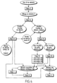
- the sorting machine 1 described above may be integrated into a more global waste treatment process, in particular to carry out a step E1 of the latter, as illustrated in Figure 2 .
- the treatment method preferably comprises step E1 during which the waste mixture 2 is separated into a first waste fraction 13 whose size is less than approximately 180 mm, preferably less than 140 mm, and a second residual waste fraction 14.
- Step E1 is advantageously carried out using a sorting machine 1 described above.
- Size is generally understood to mean a dimension of the waste space according to its greatest length, or a characteristic dimension.
- Size " of waste is understood to mean a geometric dimension characteristic of the individual waste, which allows it, for example, to pass through a mesh of corresponding size if the size of the waste is less than the size of the mesh, or on the contrary not to pass if the size of said waste is greater than the size of said mesh.
- second residual portion of waste means the remaining portion of waste, which did not correspond to the separation characteristics of the first portion of waste 13, in this case the size criterion.
- the second residual portion of waste 14 may contain waste whose size is less than 50 mm.
- the first waste fraction 13 is advantageously formed by waste having on average a higher density than the waste of the second residual waste fraction 14, to the extent that, in practice, the waste with the highest density is preferably smaller than 180 mm.
- the sorting method for sorting a waste mixture 2 is characterized in that the waste mixture 2 is introduced into a first trommel section 3 provided with a first separating wall 5 whose first length L1 is at least 1.05 times, preferably at least 1.10 times, even more preferably at least 1.12 times the second length L2 of the second trommel section 4 into which the second residual fraction of waste 14 is passed.
- step E1 of the method thus includes a separation of waste whose size is sufficiently small, whose density is the highest, whose density is the highest, whose dynamic inertia is the greatest, the most sticky, greasy, dirty and humid waste from the waste mixture 2 to form the first waste fraction.
- the latter is thus advantageously formed at least from a majority of waste having such properties.
- the first waste fraction 13 thus mainly concentrates organic and/or biodegradable waste, which most of the time has the aforementioned properties.
- the first fraction of waste 13 and the second residual fraction of waste 14 can be treated more easily in the following steps of the process, in particular in the as the waste of the second residual waste fraction 14 is, at this stage, cleaned of most of the organic and/or biodegradable, sticky, dirty and nauseating waste.
- the waste of the first waste fraction 13 has a size less than approximately 110 mm, and is separated using the sorting machine 1 previously described.
- the method comprises, at the end of step E1 or simultaneously with the latter, a step E4 of separating the second residual fraction of waste 14 into a sub-fraction of large waste and a sub-fraction of small waste 15, the sub-fraction of large waste being formed by waste whose size is greater than the sub-fraction of small waste 15.
- the sub-fraction of large waste is preferably formed by waste whose size is greater than approximately 330 mm, the sub-fraction of small waste 15 being formed by waste whose size is less than approximately 330 mm.
- Step E4 may also be carried out using the sorting machine 1 described above.
- the treatment method preferably comprises a step E5 of manual sorting of the large waste sub-fraction 16, making it possible to separate, on the one hand, the recyclable waste 26 that it contains, and on the other hand, the non-recyclable waste 27 that it contains.
- Manual sorting is advantageously made possible at this stage, insofar as the waste is of a sufficiently large size, free of small waste and most of the fines.
- the waste is advantageously free of most of the sticky and nauseating material formed by the biodegradable material, which makes manual sorting possible.
- Manual sorting makes it possible in particular to separate from the large waste sub-fraction 16 metal waste 26A, plastic waste, large electronic waste, cardboard packaging, etc.
- Waste recognized as recyclable waste during manual sorting will be advantageously sent to a recycling stage W, as described below. Residual waste that is not separated for recycling will be advantageously sent to a stage X of manufacturing solid recovered fuel, whether they are actually recyclable or not.
- the treatment method comprises a step E6 of automated sorting of the small waste sub-fraction 15, making it possible to separate on the one hand the recyclable waste 26 that it contains, and on the other hand the non-recyclable waste 27 that it contains.
- the small waste sub-fraction 15 is preferably suitable for automatic sorting, the small waste 15 being lighter to be handled for example by sorting devices.
- Step E6 preferably comprises a first sub-step E61 of separating metal waste 26A contained in the small waste sub-fraction 15, for example using an electromagnetic separator and/or an eddy current separator, so as to separate at least the majority of the metal waste 26A contained in said small waste sub-fraction 15, the metal waste 26A forming at least the majority of recyclable waste 26.
- the metal waste 26A can thus advantageously be extracted from the small waste sub-fraction 15, insofar as said small waste sub-fraction 15 is preferably substantially free of sticky biodegradable waste.
- step E6 comprises a second sub-step E62, of separating the small waste sub-fraction 15 into a stream of substantially flat waste and a stream of substantially voluminous waste.
- the two waste streams can be directed towards sorting machines adapted to the morphology of the waste they contain.
- substantially flat waste means waste that extends mainly over a surface area, such as newspapers, paper, and sheets of various plastic materials.
- substantially flat waste also advantageously includes bulky waste that is sufficiently soft, or of sufficiently low mechanical strength, to be able to be flattened or compacted easily, such as certain cardboard boxes.
- substantially voluminous waste means waste that extends in three spatial dimensions, may be hollow, and is more resistant to compaction than substantially flat waste, which is more rigid, or more solid.
- substantially voluminous waste may include plastic or glass bottles, plastic boxes, flasks and various containers.
- This sub-step E62 is preferably carried out using a ballistic belt separator (not shown).
- the ballistic belt preferably has an inclination relative to the horizontal so as to form a slope, the tread being designed to provide a forward movement in the direction of the ascent of the slope.
- the substantially voluminous waste is intended to roll and bounce on the ballistic belt by gravity so as to descend the slope towards a low recovery means of the bin or conveyor type, optionally incorporating a glass trap.
- the substantially flat waste is, for its part, preferably driven upwards of the slope by the forward movement of the belt, towards a high recovery means, for example another conveyor, so that the substantially flat waste and the substantially voluminous waste are separated.
- the fine particles likely to be contained in the small waste sub-fraction 15 advantageously adhere to the ballistic carpet (the latter may optionally be moistened to amplify this effect), and may advantageously be scraped and recovered using, for example, a tungsten belt scraper mounted on said carpet.
- the tread of the ballistic carpet may advantageously have elastic properties such as to allow the rebounding of the substantially voluminous waste.
- the ballistic belt is preferably combined with an accelerator belt mounted upstream, making it possible to accelerate the sub-fraction of small waste 15 so that the latter reaches the ballistic belt of the ballistic belt separator with a predetermined speed.
- step E6 comprises a third sub-step E63 of robotic sorting of the flow of substantially flat waste on the one hand and of the flow of waste on the other hand substantially voluminous, to separate from each of said streams recyclable waste 26 and non-recyclable waste, the third sub-step E63 being carried out at the end of the second sub-step E62.
- Separate sorting robots will advantageously be chosen and adapted respectively to the sorting of substantially flat waste on the one hand and substantially voluminous waste on the other hand.
- the sorting robots are preferably designed to separate recyclable waste from substantially flat waste and substantially voluminous waste by recognition of the latter, in particular by optical signature recognition, allowing in particular the sorting robot to detect the material of the waste to be sorted.
- the recyclable waste recognized by the sorting robots will advantageously be sent to a recycling step W.
- the unrecognized waste preferably including a small proportion of recyclable waste and a majority of non-recyclable waste, will advantageously be sent to a step X of manufacturing solid recovered fuel.
- the recyclable waste can advantageously be subject to a step T of the treatment process, during which non-ferrous metal waste is separated from recyclable waste, for example using an eddy current separator.
- the non-ferrous metal waste is, for example, formed by aluminum waste, or flexible food packaging containing aluminum foil.
- the separate streams of substantially bulky waste and substantially flat waste are conveyed using a set of belt conveyors to the sorting robots, the set of belt conveyors being designed to spread and distribute the waste in such a way that substantially no waste is superimposed on another when said waste arrives at the sorting robots.
- the efficiency of sorting by the robots is thus advantageously improved.
- Sub-steps E61, E62 and E63 are preferably carried out successively in this order.
- the treatment method preferably also comprises a step E2, carried out successively to step E1, during which the first fraction of waste 13 is subjected to a composting process so as to compost at least in part the biodegradable waste that it contains.
- Step E2 thus preferably aims to recover the first fraction of waste 13, and in particular to convert the biodegradable waste it contains into a mixture of refined waste 28, so that, preferably, the mixture of refined waste 28 forms compost satisfying standard NF U 44-051.
- Standard NF U 44-051 of 2006 called “ Organic Amendments - Names, Specifications and Marking ”, is a French standard.
- Step E2 advantageously includes the treatment of the first fraction of waste 13 by two successive composting cycles separated by a drying step of the first fraction of waste 13 at the end of the first composting cycle to facilitate the separation and easier refining of the first fraction of waste 13.
- the first fraction of waste 13 is particularly heterogeneous and contains numerous undesirable items which cannot be treated by composting, it is possible to refine the latter using step E2 to obtain refined waste 28 whose value is higher than that of the initial waste mixture.
- composting means a biological process for converting and recovering organic waste, and in particular biodegradable waste contained in the first fraction of waste 13, by promoting and/or accelerating the natural biodegradation process.
- the composting cycles of step E2 preferably make it possible to convert at least a portion of the first fraction of waste 13 into a stabilized, hygienic product, rich in humic compounds, preferably into compost.
- composting means composting, for example traditional or industrial, implementing in particular an action of micro-organisms to degrade and putrefy waste from the first fraction of waste 13, these micro-organisms being naturally present in the first fraction of waste 13 and/or added to the first fraction of waste 13, and/or caused to multiply in the first fraction of waste 13.
- This composting implements in particular an aeration of the first fraction of waste 13, and/or a regulation of the humidity of the first fraction of waste 13 (for example by adding water, and/or reintroduction into the first fraction of waste 13 of composting juice 11 emitted by the latter), and/or an addition of micro-organisms to the first fraction of waste 13 and/or an addition of structuring agents to stimulate the composting process, and/or a supply of light, for example solar.
- step A corresponds to, or comprises, a phase of degradation of the waste, in particular biodegradable waste
- step C corresponds to, or comprises, a phase of maturation of the waste, in particular biodegradable waste, to obtain the mixture of refined waste 28, the latter advantageously forming compost.
- the degradation phase advantageously results in a proliferation of microorganisms in the first fraction of waste 13, while the maturation phase preferentially results in the progressive reduction of the quantity of microorganisms having proliferated during the degradation phase, and the conservation of microorganisms beneficial for the soil.
- the degradation and maturation phases may overlap or even be combined.
- the method of the invention can advantageously be carried out using the sorting machine 1 described above.
- the invention finds its industrial application in the design, production and implementation of means for sorting a mixture of waste of various sizes, shapes and consistencies, a mixture comprising biodegradable waste and non-biodegradable recyclable waste.
Landscapes
- Engineering & Computer Science (AREA)
- Environmental & Geological Engineering (AREA)
- Combined Means For Separation Of Solids (AREA)
- Processing Of Solid Wastes (AREA)
Claims (11)
- Rotierende Sortiermaschine (1) für ein Abfallgemisch (2), wobei die Abfälle heterogene Größen, Formen und Konsistenzen aufweisen, wobei das Abfallgemisch (2) zumindest biologisch abbaubare Abfälle und nicht biologisch abbaubare, recyclingfähige Abfälle umfasst, wobei die Sortiermaschine (1) dadurch gekennzeichnet ist, dass sie mindestens umfasst:- einen ersten Trommelabschnitt (3), der mit einer ersten Trennwand (5) versehen ist, die sich über eine erste axiale Länge (L1) erstreckt und mit einer ersten Reihe von durchgehenden Trennöffnungen (7, 8), durch die das Abfallgemisch (2) in eine erste Abfallfraktion (13), die die erste Trennwand (5) über die erste Reihe von Trennöffnungen (7, 8) passiert, und in eine verbleibende, zweite Abfallfraktion (14) getrennt werden kann, wobei das Abfallgemisch (2) dazu bestimmt ist, entlang der ersten Wand zu zirkulieren, um auf diese Weise getrennt zu werden, und- einen zweiten Trommelabschnitt (4), der mit einer zweiten Trennwand (6) versehen ist, die sich über eine zweite axiale Länge (L2) erstreckt, die kürzer ist als die erste Länge (L1), wobei die zweite Trennwand (6) mit einer zweiten Reihe von durchgehenden Trennöffnungen versehen ist, die es ermöglichen, die verbleibende, zweite Abfallfraktion (14) in eine Unterfraktion von kleinteiligen Abfällen (15), die die zweite Trennwand (6) über die zweite Reihe von Trennöffnungen passiert, und in eine verbleibende Unterfraktion von großteiligen Abfällen (16) zu trennen, wobei die Unterfraktion von großteiligen Abfällen (16) aus Abfällen gebildet wird, deren Größe größer ist als die Unterfraktion von kleinteiligen Abfällen (15), wobei die verbleibende zweite Abfallfraktion (14) dazu bestimmt ist, entlang der zweiten Wand zu zirkulieren, um so getrennt zu werden,dadurch gekennzeichnet, dass die zweite Reihe von Trennöffnungen wenigstens dritte Öffnungen (9) umfasst, die wenigstens dazu beitragen, die verbleibende, zweite Abfallfraktion (14) in die Unterfraktion der kleinteiligen Abfälle (15) und die Unterfraktion des großteiligen Abfälle (16) zu trennen, indem die Unterfraktion der kleinteiligen Abfälle (15) durch die dritten Öffnungen (9) geführt werden, wobei die dritten Öffnungen (9) einen länglichen Querschnitt haben und der längliche Querschnitt einen kleinen Durchmesser (Dp) und einen großen Durchmesser (Dg) hat,die dritten Öffnungen (9) in aufeinanderfolgenden Reihen entlang der zweiten Länge (L2) verteilt sind, wobei abwechselnd mindestens:∘ eine Längsreihe (19) von dritten Öffnungen (9), bei der der große Durchmesser (Dg) der dritten Öffnungen (9) der geraden Reihe in Richtung der zweiten Länge (L2) ausgerichtet ist, und∘ eine Querreihe (20) von dritten Öffnungen (9), bei der der kleine Durchmesser (Dp) der dritten Öffnungen (9) der Querreihe (20) in Richtung der zweiten Länge (L2) ausgerichtet ist.
- Sortiermaschine (1) nach Anspruch 1, dadurch gekennzeichnet, dass die erste Länge (L 1) mindestens das 1,05-fache der zweiten Länge (L2) beträgt, vorzugsweise mindestens das 1,10-fache, überaus bevorzugt mindestens das 1,12-fache.
- Sortiermaschine (1) für ein Abfallgemisch (2) nach einem der vorhergehenden Ansprüche, dadurch gekennzeichnet, dass die erste Reihe von Trennöffnungen (7, 8) zumindest primäre Öffnungen (7) umfasst, die es ermöglichen, zumindest zur Trennung des Abfallgemisches (2) in die erste Abfallfraktion (13) und in die verbleibende, zweite Abfallfraktion (14) durch Durchgang der ersten Abfallfraktion (13) durch die primären Öffnungen (7) beizutragen, wobei letztere eine Größe haben, die geeignet ist, den Durchgang von Abfällen mit einer Größe von mehr als 80 mm zu verhindern.
- Sortiermaschine (1) für ein Abfallgemisch (2) nach einem der vorhergehenden Ansprüche, dadurch gekennzeichnet, dass die primären Öffnungen (7) einen kreisförmigen Querschnitt haben und einen Durchmesser zwischen 85 mm und 95 mm, vorzugsweise etwa 90 mm, aufweisen.
- Sortiermaschine (1) für ein Abfallgemisch (2) nach einem der Ansprüche 3 oder 4, dadurch gekennzeichnet, dass die erste Reihe von Trennöffnungen (7, 8) auch sekundäre Öffnungen (8) umfasst, die es ermöglichen dazu beitragen, das Abfallgemisch (2) in die erste Abfallfraktion (13) und in die verbleibende, zweite Abfallfraktion (14) durch Durchgang der ersten Abfallfraktion (13) durch die sekundären Öffnungen (8) zu trennen, wobei letztere von einer Größe sind, die geeignet ist, den Durchgang von Abfällen zu ermöglichen, deren Größe zwischen dem 1-fachen und 1,5-fachen der Größe der Abfälle liegt, deren Durchgang durch die primären Öffnungen (7) ermöglicht wird, wobei die sekundären Öffnungen (8) stromaufwärts von den primären Öffnungen (7) angeordnet sind, unter Berücksichtigung der Flussrichtung des Abfallgemisches (2).
- Sortiermaschine (1) für ein Abfallgemisch (2) nach dem vorhergehenden Anspruch, dadurch gekennzeichnet, dass die sekundären Öffnungen (8) einen kreisförmigen Querschnitt haben und einen Durchmesser zwischen 105 mm und 115 mm, vorzugsweise etwa 110 mm, aufweisen.
- Sortiermaschine (1) nach einem der vorhergehenden Ansprüche, dadurch gekennzeichnet, dass für jede dritte Öffnung (9) der kleine Durchmesser (Dp) zwischen 200 und 240 mm, vorzugsweise bei etwa 220 mm, liegt, der große Durchmesser (Dg) zwischen 300 und 400 mm, vorzugsweise bei etwa 330 mm, liegt, wobei der kleine Durchmesser (Dp) im Wesentlichen senkrecht zum großen Durchmesser (Dg) verläuft.
- Sortiermaschine (1) nach einem der vorhergehenden Ansprüche, dadurch gekennzeichnet, dass die Trennöffnungen (7, 8) der ersten Reihe von Trennöffnungen (7, 8) in einer ersten versetzten Anordnung über die erste Trennwand (5) verteilt sind, wobei die Trennöffnungen der zweiten Reihe von Trennöffnungen in einer zweiten versetzten Anordnung über die zweite Trennwand (6) verteilt sind.
- Sortiermaschine (1) nach einem der vorhergehenden Ansprüche, dadurch gekennzeichnet, dass der erste Trommelabschnitt (3) und der zweite Trommelabschnitt (4) jeweils dazu eingerichtet sind, dass sie in Drehung versetzt werden können, wobei die Drehung abwechselnd in eine Richtung und in die andere Richtung gemäß einer gewünschten Frequenz erfolgt.
- Verfahren zum Sortieren eines Abfallgemisches (2) mit heterogenen Größen, Formen und Konsistenzen, das zumindest biologisch abbaubare Abfälle und nicht biologisch abbaubare, recyclingfähige Abfälle umfasst, wobei ein nicht unerheblicher Teil der Masse des Abfallgemisches aus biologisch abbaubaren Abfällen besteht, beispielsweise mindestens 10 % der Masse, und ein nicht unerheblicher Teil der Masse des Gemisches aus nicht biologisch abbaubaren, recyclingfähigen Abfällen besteht, beispielsweise mindestens 10 % der Masse, wobei das Verfahren zum Sortieren dadurch gekennzeichnet ist, dass folgendermaßen vorgegangen wird:- Einleiten des Abfallgemisches (2) in einen ersten Trommelabschnitt (3), der mit einer ersten Trennwand (5) versehen ist, die sich über eine erste axiale Länge (L1) erstreckt und mit einer ersten Reihe von durchgehenden Trennöffnungen (7, 8) versehen ist,- Trennen des Abfallgemisches (2) in eine erste Abfallfraktion (13), die die erste Trennwand (5) über die erste Reihe von Trennöffnungen (7, 8) passiert, und in eine verbleibende, zweite Abfallfraktion (14), wobei das Abfallgemisch (2) entlang der ersten Wand zirkuliert, um so getrennt zu werden,- Durchleiten der verbleibenden, zweiten Abfallfraktion (14) von dem ersten Trommelabschnitt (3) zu einem zweiten Trommelabschnitt (4), der mit einer zweiten Trennwand (6) versehen ist, die sich über eine zweite axiale Länge (L2) erstreckt, die kleiner ist als die erste Länge (L1), wobei die zweite Trennwand (6) mit einer zweiten Reihe von durchgehenden Trennöffnungen versehen ist,- Trennen der verbleibenden, zweiten Abfallfraktion (14) in eine Unterfraktion von kleinteiligen Abfällen (15), die die zweite Trennwand (6) durch die zweite Reihe von Trennöffnungen passiert, und in eine verbleibende Unterfraktion von großteiligen Abfällen (16), wobei die Unterfraktion von großteiligen Abfällen (16) aus Abfällen gebildet wird, deren Größe größer ist als die Unterfraktion von kleinteiligen Abfällen (15), wobei die verbleibende zweite Abfallfraktion (14) dazu bestimmt ist, entlang der zweiten Wand zu zirkulieren, um so getrennt zu werden, die zweite Reihe von Trennöffnungen wenigstens dritte Öffnungen (9) umfasst, die wenigstens dazu beitragen, die verbleibende, zweite Abfallfraktion (14) in die Unterfraktion der kleinteiligen Abfälle (15) und die Unterfraktion des großteiligen Abfälle (16) zu trennen, indem die Unterfraktion der kleinteiligen Abfälle (15) durch die dritten Öffnungen (9) geführt werden, wobei die dritten Öffnungen (9) einen länglichen Querschnitt haben und der längliche Querschnitt einen kleinen Durchmesser (Dp) und einen großen Durchmesser (Dg) hat,
die dritten Öffnungen (9) in aufeinanderfolgenden Reihen entlang der zweiten Länge (L2) verteilt sind, wobei abwechselnd mindestens:∘ eine Längsreihe (19) von dritten Öffnungen (9), bei der der große Durchmesser (Dg) der dritten Öffnungen (9) der geraden Reihe in Richtung der zweiten Länge (L2) ausgerichtet ist, und∘ eine Querreihe (20) von dritten Öffnungen (9), bei der der kleine Durchmesser (Dp) der dritten Öffnungen (9) der Querreihe (20) in Richtung der zweiten Länge (L2) ausgerichtet ist. - Verfahren zum Sortieren eines Abfallgemisches (2) nach Anspruch 10, dadurch gekennzeichnet, dass das Abfallgemisch (2) in einen ersten Trommelabschnitt (3) eingeführt wird, der mit einer ersten Trennwand (5) versehen ist, deren erste Länge (L1) mindestens 1,05-mal, bevorzugt mindestens 1,10-mal, noch bevorzugter mindestens 1,12-mal die zweite Länge (L2) des zweiten Trommelabschnitts (4) beträgt, in den die verbleibende, zweite Abfallfraktion (14) geleitet wird.
Applications Claiming Priority (2)
| Application Number | Priority Date | Filing Date | Title |
|---|---|---|---|
| FR1454709A FR3021235B1 (fr) | 2014-05-23 | 2014-05-23 | Machine de tri d'un melange de dechets, et procede de tri associe |
| PCT/FR2015/051372 WO2015197928A1 (fr) | 2014-05-23 | 2015-05-22 | Machine de tri d'un melange de dechets, et procede de tri associe |
Publications (3)
| Publication Number | Publication Date |
|---|---|
| EP3145644A1 EP3145644A1 (de) | 2017-03-29 |
| EP3145644C0 EP3145644C0 (de) | 2025-05-07 |
| EP3145644B1 true EP3145644B1 (de) | 2025-05-07 |
Family
ID=51518945
Family Applications (1)
| Application Number | Title | Priority Date | Filing Date |
|---|---|---|---|
| EP15734425.0A Active EP3145644B1 (de) | 2014-05-23 | 2015-05-22 | Vorrichung und verfahren zur abfalltrennung |
Country Status (17)
| Country | Link |
|---|---|
| US (1) | US10086406B2 (de) |
| EP (1) | EP3145644B1 (de) |
| KR (1) | KR20170008305A (de) |
| AU (1) | AU2015279024B2 (de) |
| CA (1) | CA2949919C (de) |
| CU (1) | CU24469B1 (de) |
| DO (1) | DOP2016000305A (de) |
| FR (1) | FR3021235B1 (de) |
| MA (1) | MA39546B2 (de) |
| MX (1) | MX2016015320A (de) |
| MY (1) | MY179823A (de) |
| NZ (1) | NZ727154A (de) |
| PH (1) | PH12016502326B1 (de) |
| RU (1) | RU2721672C2 (de) |
| SG (1) | SG11201609833QA (de) |
| WO (1) | WO2015197928A1 (de) |
| ZA (1) | ZA201608481B (de) |
Families Citing this family (7)
| Publication number | Priority date | Publication date | Assignee | Title |
|---|---|---|---|---|
| KR101995750B1 (ko) * | 2016-12-28 | 2019-07-03 | 이기주 | 다슬기 선별장치 |
| CA3080426A1 (en) | 2017-10-27 | 2019-05-02 | Beta Hatch Inc. | Systems and methods for sorting insects |
| CN110396429B (zh) * | 2019-07-26 | 2021-09-17 | 四川通成浩业达环保科技开发有限公司 | 垃圾气化处理系统及其自动温控方法 |
| EP3912736B1 (de) * | 2020-05-20 | 2024-09-04 | Gericke Ltd. | Siebvorrichtung und verfahren zur herstellung derselben |
| CN112325589B (zh) * | 2020-11-17 | 2022-09-13 | 江苏绿都环境工程有限公司 | 一种自动筛选均衡烘干的滚筒烘干机 |
| DE102022106905B3 (de) * | 2022-03-23 | 2023-01-05 | Jörg K. Müller | Verfahren zur Gewinnung eines feinkrümeligen Kultursubstrats und dessen Verwendung |
| AU2023398799A1 (en) * | 2022-12-14 | 2025-07-31 | Thomas A. Valerio | Trommel with elongated slots for plastics separation |
Citations (2)
| Publication number | Priority date | Publication date | Assignee | Title |
|---|---|---|---|---|
| KR101196161B1 (ko) * | 2009-12-07 | 2012-11-01 | 코오롱글로벌 주식회사 | 트로멜 |
| FR2977813A1 (fr) * | 2011-07-11 | 2013-01-18 | Martin Champel | Dispositif de tri granulometrique a coupure reglable a l'arret et en fonctionnement |
Family Cites Families (16)
| Publication number | Priority date | Publication date | Assignee | Title |
|---|---|---|---|---|
| GB127783A (en) * | 1918-11-29 | 1919-06-12 | John Thompson | Revolving Screen and Separator. |
| FR548985A (fr) * | 1922-03-15 | 1923-01-30 | Karpeles Company | Perfectionnements aux machines à trier |
| GB247315A (en) * | 1924-11-21 | 1926-02-18 | Ralph Hugh Kirkup | Rotary screen for screening coal, coke, stone and like material |
| US5009370A (en) * | 1989-05-11 | 1991-04-23 | New Life Foundation | Municipal solid waste material sorting trommel system |
| DE4005331A1 (de) * | 1990-02-20 | 1991-08-22 | Doppstadt Werner | Abfallaufbereitungsanlage |
| US5108584A (en) * | 1990-10-09 | 1992-04-28 | Raymond Brosseuk | Apparatus for extrating heavy metals from ore |
| FR2668398B1 (fr) * | 1990-10-25 | 1992-12-24 | Otv D | Procede et dispositif pour extraire la matiere organique contenue dans les dechets menagers. |
| RU2038869C1 (ru) * | 1992-09-16 | 1995-07-09 | Александр Геннадьевич Бирюков | Устройство для разделения сыпучих материалов по крупности частиц |
| US6019227A (en) * | 1994-11-16 | 2000-02-01 | May, Iii; Alexander Douglas | Extractor and separator apparatus |
| KR100351733B1 (ko) * | 2000-03-21 | 2002-09-05 | 김구회 | 2단 역회전 매립토사 쓰레기 선별장치 |
| KR100683891B1 (ko) * | 2006-05-24 | 2007-02-16 | 주식회사 남부환경개발 | 요동식 분산수단이 포함된 비위생 매립폐기물 선별장치 |
| RU2359758C2 (ru) * | 2007-05-21 | 2009-06-27 | Виталий Иванович Малюков | Линия сортировки многокомпонентной смеси |
| ES2298094B1 (es) * | 2007-11-26 | 2009-02-16 | Joar, S.L. | Tromel clasificador rotativo para la recuperacion de residuos solidos urbanos. |
| GB2466215A (en) * | 2008-12-12 | 2010-06-16 | Mbl Ip | Wet recyclable material processing |
| EP2253388A1 (de) * | 2009-05-20 | 2010-11-24 | Gösta Larssons Mekaniska Verkstad AB | Zentrifugalsieb |
| RU2397031C1 (ru) * | 2009-10-06 | 2010-08-20 | Юрий Алексеевич Парахин | Устройство для переработки твердых бытовых отходов |
-
2014
- 2014-05-23 FR FR1454709A patent/FR3021235B1/fr active Active
-
2015
- 2015-05-22 RU RU2016148697A patent/RU2721672C2/ru active
- 2015-05-22 MX MX2016015320A patent/MX2016015320A/es unknown
- 2015-05-22 NZ NZ727154A patent/NZ727154A/en unknown
- 2015-05-22 WO PCT/FR2015/051372 patent/WO2015197928A1/fr not_active Ceased
- 2015-05-22 CU CU2016000177A patent/CU24469B1/es unknown
- 2015-05-22 CA CA2949919A patent/CA2949919C/en active Active
- 2015-05-22 KR KR1020167036154A patent/KR20170008305A/ko not_active Ceased
- 2015-05-22 EP EP15734425.0A patent/EP3145644B1/de active Active
- 2015-05-22 SG SG11201609833QA patent/SG11201609833QA/en unknown
- 2015-05-22 US US15/313,459 patent/US10086406B2/en active Active
- 2015-05-22 MA MA39546A patent/MA39546B2/fr unknown
- 2015-05-22 AU AU2015279024A patent/AU2015279024B2/en not_active Ceased
- 2015-05-22 MY MYPI2016704305A patent/MY179823A/en unknown
-
2016
- 2016-11-22 PH PH12016502326A patent/PH12016502326B1/en unknown
- 2016-11-22 DO DO2016000305A patent/DOP2016000305A/es unknown
- 2016-12-08 ZA ZA2016/08481A patent/ZA201608481B/en unknown
Patent Citations (2)
| Publication number | Priority date | Publication date | Assignee | Title |
|---|---|---|---|---|
| KR101196161B1 (ko) * | 2009-12-07 | 2012-11-01 | 코오롱글로벌 주식회사 | 트로멜 |
| FR2977813A1 (fr) * | 2011-07-11 | 2013-01-18 | Martin Champel | Dispositif de tri granulometrique a coupure reglable a l'arret et en fonctionnement |
Also Published As
| Publication number | Publication date |
|---|---|
| CU24469B1 (es) | 2020-02-04 |
| MX2016015320A (es) | 2017-05-09 |
| SG11201609833QA (en) | 2016-12-29 |
| MY179823A (en) | 2020-11-17 |
| AU2015279024B2 (en) | 2020-01-30 |
| CA2949919A1 (en) | 2015-12-30 |
| MA39546A1 (fr) | 2018-03-30 |
| AU2015279024A1 (en) | 2017-01-05 |
| RU2016148697A3 (de) | 2018-12-21 |
| RU2721672C2 (ru) | 2020-05-21 |
| EP3145644C0 (de) | 2025-05-07 |
| PH12016502326B1 (en) | 2021-06-18 |
| WO2015197928A1 (fr) | 2015-12-30 |
| CA2949919C (en) | 2022-08-02 |
| PH12016502326A1 (en) | 2017-02-06 |
| US20170151585A1 (en) | 2017-06-01 |
| NZ727154A (en) | 2021-03-26 |
| FR3021235A1 (fr) | 2015-11-27 |
| RU2016148697A (ru) | 2018-06-26 |
| FR3021235B1 (fr) | 2020-07-03 |
| KR20170008305A (ko) | 2017-01-23 |
| EP3145644A1 (de) | 2017-03-29 |
| MA39546B2 (fr) | 2021-01-29 |
| ZA201608481B (en) | 2021-07-28 |
| US10086406B2 (en) | 2018-10-02 |
| DOP2016000305A (es) | 2017-02-15 |
Similar Documents
| Publication | Publication Date | Title |
|---|---|---|
| EP3145644B1 (de) | Vorrichung und verfahren zur abfalltrennung | |
| EP3145898B1 (de) | Verfahren zur behandlung eines abfallgemisches, einschliesslich trennung und kompostierung des besagten gemisches | |
| CA2028308A1 (fr) | Procede de traitement de dechets pour la recuperation de matiere organique et dispositif pour sa mise en oeuvre | |
| WO2011027255A1 (fr) | Procédé et installation de recyclage de déchets de plâtre | |
| CH619159A5 (de) | ||
| EP3145636B1 (de) | Verfahren zur behandlung eines abfallgemischs mit zwei kompostierungszyklen | |
| EP4051435B1 (de) | Behandlungsanlage mit optimierter densitometrischer sortierung und entsprechendes behandlungsverfahren | |
| EP2364782B1 (de) | Verfahren und Vorrichtung zur Behandlung der Schwerstoffe, welche von einer Abfallsortierung herrühren | |
| FR2930459A1 (fr) | Dispositif de tri de dechets notamment menagers. | |
| CA3013050A1 (fr) | Machine de criblage | |
| CH620606A5 (en) | Installation for converting household waste into a combustible product | |
| EP2830774B1 (de) | Verfahren zur behandlung von abfällen, insbesondere hausmüll, und anlage zur durchführung von diesem verfahren | |
| OA18482A (fr) | Machine de tri d'un mélange de déchets, et procédé de tri associé. | |
| OA19119A (en) | Procédé et installation de traitement d'un mélange de déchets incluant une séparation et un compostage dudit mélange. | |
| EP3119537B1 (de) | Verfahren zur behandlung von abfällen, insbesondere hausmüll, sowie anlage zur durchführung des verfahrens | |
| FR2793172A1 (fr) | Procede de valorisation de matiere | |
| BE416296A (de) | ||
| OA19118A (en) | Procédé et installation de traitement d'un mélange de déchets à deux cycles de compostage. | |
| EP2421945A1 (de) | Anlage und verfahren zur herstellung von festem brennstoff aus recycling |
Legal Events
| Date | Code | Title | Description |
|---|---|---|---|
| STAA | Information on the status of an ep patent application or granted ep patent |
Free format text: STATUS: THE INTERNATIONAL PUBLICATION HAS BEEN MADE |
|
| PUAI | Public reference made under article 153(3) epc to a published international application that has entered the european phase |
Free format text: ORIGINAL CODE: 0009012 |
|
| STAA | Information on the status of an ep patent application or granted ep patent |
Free format text: STATUS: REQUEST FOR EXAMINATION WAS MADE |
|
| 17P | Request for examination filed |
Effective date: 20161222 |
|
| AK | Designated contracting states |
Kind code of ref document: A1 Designated state(s): AL AT BE BG CH CY CZ DE DK EE ES FI FR GB GR HR HU IE IS IT LI LT LU LV MC MK MT NL NO PL PT RO RS SE SI SK SM TR |
|
| AX | Request for extension of the european patent |
Extension state: BA ME |
|
| DAV | Request for validation of the european patent (deleted) | ||
| RAX | Requested extension states of the european patent have changed |
Extension state: ME Payment date: 20161222 |
|
| STAA | Information on the status of an ep patent application or granted ep patent |
Free format text: STATUS: EXAMINATION IS IN PROGRESS |
|
| 17Q | First examination report despatched |
Effective date: 20210325 |
|
| RAP3 | Party data changed (applicant data changed or rights of an application transferred) |
Owner name: GROUPE VACHER |
|
| GRAP | Despatch of communication of intention to grant a patent |
Free format text: ORIGINAL CODE: EPIDOSNIGR1 |
|
| STAA | Information on the status of an ep patent application or granted ep patent |
Free format text: STATUS: GRANT OF PATENT IS INTENDED |
|
| RIC1 | Information provided on ipc code assigned before grant |
Ipc: B07B 1/46 20060101ALI20241129BHEP Ipc: B07B 13/04 20060101ALI20241129BHEP Ipc: B07B 1/24 20060101ALI20241129BHEP Ipc: B07B 1/22 20060101AFI20241129BHEP |
|
| INTG | Intention to grant announced |
Effective date: 20241223 |
|
| GRAS | Grant fee paid |
Free format text: ORIGINAL CODE: EPIDOSNIGR3 |
|
| GRAA | (expected) grant |
Free format text: ORIGINAL CODE: 0009210 |
|
| STAA | Information on the status of an ep patent application or granted ep patent |
Free format text: STATUS: THE PATENT HAS BEEN GRANTED |
|
| AK | Designated contracting states |
Kind code of ref document: B1 Designated state(s): AL AT BE BG CH CY CZ DE DK EE ES FI FR GB GR HR HU IE IS IT LI LT LU LV MC MK MT NL NO PL PT RO RS SE SI SK SM TR |
|
| REG | Reference to a national code |
Ref country code: GB Ref legal event code: FG4D Free format text: NOT ENGLISH |
|
| REG | Reference to a national code |
Ref country code: CH Ref legal event code: EP |
|
| REG | Reference to a national code |
Ref country code: DE Ref legal event code: R096 Ref document number: 602015091587 Country of ref document: DE |
|
| REG | Reference to a national code |
Ref country code: IE Ref legal event code: FG4D Free format text: LANGUAGE OF EP DOCUMENT: FRENCH |
|
| U01 | Request for unitary effect filed |
Effective date: 20250605 |
|
| U07 | Unitary effect registered |
Designated state(s): AT BE BG DE DK EE FI FR IT LT LU LV MT NL PT RO SE SI Effective date: 20250613 |
|
| U20 | Renewal fee for the european patent with unitary effect paid |
Year of fee payment: 11 Effective date: 20250610 |
|
| PG25 | Lapsed in a contracting state [announced via postgrant information from national office to epo] |
Ref country code: ES Free format text: LAPSE BECAUSE OF FAILURE TO SUBMIT A TRANSLATION OF THE DESCRIPTION OR TO PAY THE FEE WITHIN THE PRESCRIBED TIME-LIMIT Effective date: 20250507 |
|
| PG25 | Lapsed in a contracting state [announced via postgrant information from national office to epo] |
Ref country code: NO Free format text: LAPSE BECAUSE OF FAILURE TO SUBMIT A TRANSLATION OF THE DESCRIPTION OR TO PAY THE FEE WITHIN THE PRESCRIBED TIME-LIMIT Effective date: 20250807 Ref country code: GR Free format text: LAPSE BECAUSE OF FAILURE TO SUBMIT A TRANSLATION OF THE DESCRIPTION OR TO PAY THE FEE WITHIN THE PRESCRIBED TIME-LIMIT Effective date: 20250808 |
|
| PG25 | Lapsed in a contracting state [announced via postgrant information from national office to epo] |
Ref country code: PL Free format text: LAPSE BECAUSE OF FAILURE TO SUBMIT A TRANSLATION OF THE DESCRIPTION OR TO PAY THE FEE WITHIN THE PRESCRIBED TIME-LIMIT Effective date: 20250507 |
|
| PG25 | Lapsed in a contracting state [announced via postgrant information from national office to epo] |
Ref country code: HR Free format text: LAPSE BECAUSE OF FAILURE TO SUBMIT A TRANSLATION OF THE DESCRIPTION OR TO PAY THE FEE WITHIN THE PRESCRIBED TIME-LIMIT Effective date: 20250507 |
|
| PG25 | Lapsed in a contracting state [announced via postgrant information from national office to epo] |
Ref country code: RS Free format text: LAPSE BECAUSE OF FAILURE TO SUBMIT A TRANSLATION OF THE DESCRIPTION OR TO PAY THE FEE WITHIN THE PRESCRIBED TIME-LIMIT Effective date: 20250807 |
|
| PG25 | Lapsed in a contracting state [announced via postgrant information from national office to epo] |
Ref country code: IS Free format text: LAPSE BECAUSE OF FAILURE TO SUBMIT A TRANSLATION OF THE DESCRIPTION OR TO PAY THE FEE WITHIN THE PRESCRIBED TIME-LIMIT Effective date: 20250907 |
|
| REG | Reference to a national code |
Ref country code: CH Ref legal event code: H13 Free format text: ST27 STATUS EVENT CODE: U-0-0-H10-H13 (AS PROVIDED BY THE NATIONAL OFFICE) Effective date: 20251223 |
|
| PG25 | Lapsed in a contracting state [announced via postgrant information from national office to epo] |
Ref country code: SM Free format text: LAPSE BECAUSE OF FAILURE TO SUBMIT A TRANSLATION OF THE DESCRIPTION OR TO PAY THE FEE WITHIN THE PRESCRIBED TIME-LIMIT Effective date: 20250507 |
|
| PG25 | Lapsed in a contracting state [announced via postgrant information from national office to epo] |
Ref country code: CH Free format text: LAPSE BECAUSE OF NON-PAYMENT OF DUE FEES Effective date: 20250531 |
|
| PG25 | Lapsed in a contracting state [announced via postgrant information from national office to epo] |
Ref country code: CZ Free format text: LAPSE BECAUSE OF FAILURE TO SUBMIT A TRANSLATION OF THE DESCRIPTION OR TO PAY THE FEE WITHIN THE PRESCRIBED TIME-LIMIT Effective date: 20250507 |
|
| PG25 | Lapsed in a contracting state [announced via postgrant information from national office to epo] |
Ref country code: SK Free format text: LAPSE BECAUSE OF FAILURE TO SUBMIT A TRANSLATION OF THE DESCRIPTION OR TO PAY THE FEE WITHIN THE PRESCRIBED TIME-LIMIT Effective date: 20250507 |