EP3144913B1 - Système, appareil et procédé pour faciliter la communication d'un système d'alarme - Google Patents
Système, appareil et procédé pour faciliter la communication d'un système d'alarme Download PDFInfo
- Publication number
- EP3144913B1 EP3144913B1 EP16189064.5A EP16189064A EP3144913B1 EP 3144913 B1 EP3144913 B1 EP 3144913B1 EP 16189064 A EP16189064 A EP 16189064A EP 3144913 B1 EP3144913 B1 EP 3144913B1
- Authority
- EP
- European Patent Office
- Prior art keywords
- alarm system
- web server
- format
- alarm
- customer terminal
- Prior art date
- Legal status (The legal status is an assumption and is not a legal conclusion. Google has not performed a legal analysis and makes no representation as to the accuracy of the status listed.)
- Active
Links
- 230000006854 communication Effects 0.000 title claims description 95
- 238000004891 communication Methods 0.000 title claims description 95
- 238000000034 method Methods 0.000 title claims description 18
- 230000005540 biological transmission Effects 0.000 claims description 13
- 230000004044 response Effects 0.000 claims description 3
- 230000001413 cellular effect Effects 0.000 description 16
- 230000008859 change Effects 0.000 description 4
- 238000010586 diagram Methods 0.000 description 4
- 230000011664 signaling Effects 0.000 description 4
- 230000006870 function Effects 0.000 description 3
- 230000000007 visual effect Effects 0.000 description 3
- 238000012544 monitoring process Methods 0.000 description 2
- 230000008569 process Effects 0.000 description 2
- 230000007175 bidirectional communication Effects 0.000 description 1
- 238000004590 computer program Methods 0.000 description 1
- UFEODZBUAFNAEU-NLRVBDNBSA-N fluoxastrobin Chemical compound C=1C=CC=C(OC=2C(=C(OC=3C(=CC=CC=3)Cl)N=CN=2)F)C=1C(=N/OC)\C1=NOCCO1 UFEODZBUAFNAEU-NLRVBDNBSA-N 0.000 description 1
- 238000012986 modification Methods 0.000 description 1
- 230000004048 modification Effects 0.000 description 1
- 239000013307 optical fiber Substances 0.000 description 1
Images


Classifications
-
- G—PHYSICS
- G08—SIGNALLING
- G08B—SIGNALLING OR CALLING SYSTEMS; ORDER TELEGRAPHS; ALARM SYSTEMS
- G08B25/00—Alarm systems in which the location of the alarm condition is signalled to a central station, e.g. fire or police telegraphic systems
- G08B25/007—Details of data content structure of message packets; data protocols
-
- G—PHYSICS
- G08—SIGNALLING
- G08B—SIGNALLING OR CALLING SYSTEMS; ORDER TELEGRAPHS; ALARM SYSTEMS
- G08B25/00—Alarm systems in which the location of the alarm condition is signalled to a central station, e.g. fire or police telegraphic systems
- G08B25/01—Alarm systems in which the location of the alarm condition is signalled to a central station, e.g. fire or police telegraphic systems characterised by the transmission medium
- G08B25/10—Alarm systems in which the location of the alarm condition is signalled to a central station, e.g. fire or police telegraphic systems characterised by the transmission medium using wireless transmission systems
-
- G—PHYSICS
- G08—SIGNALLING
- G08B—SIGNALLING OR CALLING SYSTEMS; ORDER TELEGRAPHS; ALARM SYSTEMS
- G08B25/00—Alarm systems in which the location of the alarm condition is signalled to a central station, e.g. fire or police telegraphic systems
- G08B25/01—Alarm systems in which the location of the alarm condition is signalled to a central station, e.g. fire or police telegraphic systems characterised by the transmission medium
- G08B25/08—Alarm systems in which the location of the alarm condition is signalled to a central station, e.g. fire or police telegraphic systems characterised by the transmission medium using communication transmission lines
-
- H—ELECTRICITY
- H04—ELECTRIC COMMUNICATION TECHNIQUE
- H04L—TRANSMISSION OF DIGITAL INFORMATION, e.g. TELEGRAPHIC COMMUNICATION
- H04L12/00—Data switching networks
- H04L12/28—Data switching networks characterised by path configuration, e.g. LAN [Local Area Networks] or WAN [Wide Area Networks]
- H04L12/46—Interconnection of networks
- H04L12/4604—LAN interconnection over a backbone network, e.g. Internet, Frame Relay
- H04L12/462—LAN interconnection over a bridge based backbone
- H04L12/4625—Single bridge functionality, e.g. connection of two networks over a single bridge
-
- H—ELECTRICITY
- H04—ELECTRIC COMMUNICATION TECHNIQUE
- H04L—TRANSMISSION OF DIGITAL INFORMATION, e.g. TELEGRAPHIC COMMUNICATION
- H04L12/00—Data switching networks
- H04L12/66—Arrangements for connecting between networks having differing types of switching systems, e.g. gateways
-
- H—ELECTRICITY
- H04—ELECTRIC COMMUNICATION TECHNIQUE
- H04L—TRANSMISSION OF DIGITAL INFORMATION, e.g. TELEGRAPHIC COMMUNICATION
- H04L67/00—Network arrangements or protocols for supporting network services or applications
- H04L67/01—Protocols
- H04L67/02—Protocols based on web technology, e.g. hypertext transfer protocol [HTTP]
Definitions
- This disclosure relates to a system, apparatus and method of communicating with and controlling an alarm system.
- alarm systems are designed to communicate with a monitoring station to report alarms and other conditions at the monitored premises via the public switched telephone network (PSTN).
- PSTN public switched telephone network
- Many alarm systems can also be configured to directly contact the end user on the occurrence of various predefined conditions. If so configured, when any of these conditions occur, the alarm system notifies the end user by placing a telephone call to the end user's cellular telephone and playing a sequence of tones or playing a voice recording.
- Other notification techniques include sending an SMS and/or email.
- the end user can remotely control their alarm system by calling it via the PSTN and using DTMF (touch-) tones to arm and disarm their system.
- Embodiments are intended to mitigate one or more of these limitations.
- One embodiment enables alarm systems designed to communicate over the PSTN to enjoy the benefits of modern cellular networks as well as wired and wireless broadband networks.
- US patent US7253728 (UHS Systems Pty Ltd) discloses a customer terminal adapted to convert alarm system signals to a format suitable for transmission via data packets.
- Other related art includes WO2015/013756 which relates to improvements in central station connectivity, and US2008/0025487 which relates to a telemetry system.
- the web server is adapted to convert the instructions in the first format to an intermediate format and to send the instructions in the intermediate to the local communication interface, and the local communication interface is adapted to convert the instructions in the intermediate format to the alarm system format for transmission to the alarm system.
- the web server can be adapted to receive information from the alarm system.
- the web server can be adapted to store information from the alarm system.
- the web server is adapted to send information to the remote device in response to a request from the remote device.
- the web server can be adapted to transmit designated information to the remote device.
- the customer terminal can include a second communication interface adapted to connect with the alarm system via which the alarm system can be adapted to send information to the customer terminal.
- an alarm transmission system including a customer terminal, and a remote device adapted to communicate with the web server via at least one of the external communication networks.
- a method of sending instructions from a remote device to an alarm system via an alarm transmission system including: logging the remote device on to the web server; sending instructions in a first format from the remote device to the web server; converting the instructions in the first format to an alarm system format; sending the instructions in the alarm system format to the alarm system.
- the method can further include: converting the instructions in the first format to an intermediate format; and converting the instructions in the intermediate format to the alarm system format before sending the instructions in the alarm system format.
- a further embodiment provides a method of storing alarm system information in a customer terminal including: receiving information in the alarm system format from the alarm system; and converting the information in the alarm system format from the alarm system to the first format; and storing the information in the first format in the web server.
- the method of storing alarm system information can further include: converting the instructions in the alarm system format to an intermediate format; and converting the instructions in the intermediate format to the first format before storing the instructions in the first format.
- the first alarm system interface can be a keypad bus (KPB) interface.
- KPB keypad bus
- the customer terminal may include a second alarm system interface adapted to be connected to an alarm communication path of the alarm system (1.003).
- the CT can include a first communicator (1.014) adapted to communicate with the alarm system via a second alarm system interface (1.003).
- the alarm system can be integrated with the customer terminal.
- the web server can be adapted to send first messages to the alarm system via the first alarm system interface (1.005).
- the web server can be adapted to receive second messages from the alarm system via the first alarm system interface (1.005).
- the web server can be adapted to receive third messages via one or more of the network interfaces (1.017.4 and 1.034).
- the web server can be adapted to send fourth messages via one or more of the network interfaces (1.017.4 and 1.034).
- the customer terminal can be adapted to distinguish two or more of different types of signals received via the first alarm system interface.
- the different types of signals can include one or more of acknowledgement signals, alarm signals, and status signals.
- the customer terminal can include a second communicator (1.014) connected with an alarm sender (1.006) of the alarm system.
- the web server can be connected to the communicator via at least one CT internal communication path (1.017.1).
- the CT communication path can include a local communication network.
- the CT communication path can include an internal local area network (LAN) (1.017.1).
- LAN local area network
- the communicator (1.014) can be adapted to convert signals on the alarm communication path to at least one format suitable for transmission via at least one external communication network (1.022, 1.024).
- the communicator (1.014) can be adapted to enable bi-directional communication between the alarm system and at least one external communication network (1.022, 1.024).
- the communicator (1.014) can be adapted to communicate alarm status information to the web server (1.018).
- the web server (1.018) can be connected to the alarm system via a communication path (1.005).
- the first communication path can be a keypad bus (KPB) (1.005).
- KPB keypad bus
- the web server (1.018) can be adapted to enable control of the alarm system via at least one external communication network (1.022, 1.024).
- the web server can be adapted to enable control signals to be sent via at least one external communication network to the alarm system via the KPB.
- the web server can be adapted to receive and store information from the KPB.
- the web server can be adapted to transmit stored information via said at least one external communication network.
- the web server can be adapted to convert information received from the alarm system into a first format.
- the web server can be adapted to transmit stored information via said at least one external communication network in response to a request received via one of the said at least one external communication networks.
- a remote communication device (1.030) can communicate with the web server via said at least one external communication network.
- the remote communication device can be used to control at least one function of the alarm system via the web server.
- a function of the customer terminal is to mediate communications between the alarm system and one or more external communication systems.
- an alarm transmission system including a customer terminal, and a remote device adapted to communicate with the web server via at least one of the external communication networks.
- a method of sending instructions from a remote device to an alarm system via a customer terminal including: logging the remote device on to the web server; sending instructions from the remote device to the web server in a first format; converting the instructions to the second format; sending the instructions to the alarm system.
- the method can further include: receiving information from the alarm system; and converting information in the second format from the alarm system to the first format; and storing the information in the web server.
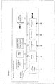
- Figure 1 shows alarm and broadband equipment at a typical customer premises (1.007) including a communication arrangement according to an embodiment.
- An alarm system 1.002 and associated keypad 1.008 can be connected to one or more external communication networks 1.022, 1.024 via customer terminal 1.000.
- the alarm system 1.002 includes an alarm processor 1.004 having one or more alarm detector inputs 1.001, alarm interface 1.004.2, an alarm processor 1.004 and associated keypad interface 1.004.1 and an alarm sender or digital dialer (DD) 1.006.
- Keypad (1.008) provides a local user interface for the alarm system (1.002) panel and is connected to the alarm processor via keypad bus 1.005 and associated keypad bus interface 1.004.1.
- the alarm processor keypad interface 1.004.1 formats communication to and from the alarm processor 1.004 and the keypad bus 1.005.
- the alarm interface (1.004.2) formats communications between the alarm processor 1.004 and alarm sensors connected to alarm inputs 1.001.
- the keypad includes a keypad processor 1.010 with associated keypad interface 1.010.1, keys 1.011, and a display or visual indicator 1.012.
- the keypad interface 1.010.1 formats communication to and from the keypad processor 1.010 and the keypad bus 1.005.
- the customer terminal 1.000 includes a communicator 1.014 and a web server 1.018 connected to one or more internal communications links 1.017.1, 1.017.2 which facilitate communications with one or more external networks 1.022, 1.024.
- the communicator includes a first communication adapter interface 1.014.1 connected to a first internal LAN 1.017.1, and second communications adapter interface 1.014.2 connected to a second internal LAN 1.017.2.
- the web server 1.018 includes first web server interface 1.018.1 connected to first internal LAN 1.017.1 and second web server interface 1.018.2 connected to second internal LAN 1.017.2.
- the first internal LAN can provide a communication path to an external wired network 1.022.
- the second internal LAN can interchangeably connect the web server and the communicator with a wireless transceiver such as a cellular transceiver 1.034 which facilitates wireless communication with an external wireless network such as cellular network 1.024.
- the web server 1.018 includes a third web server interface 1.026 through which the web server is adapted to communicate with the alarm system 1.002 via keypad bus 1.005.
- the customer premises may include a premises wired or wireless LAN 1.016 to which other devices such as computer 1.020 can be connected.
- the first internal LAN 1.017.1 can be connected to the premises LAN 1.016 using wireless (WiFi) or Ethernet 1.017.4.
- the premises LAN 1.016 can connect to an external wide area network such as data network 1.022. This provides one communications path for the customer terminal 1.000 to connect to external agencies such as an alarm monitoring centre or automation system 1.200 via the wide area network.
- the internal LAN 1.017.2 can communicate via external wireless network 1.024, providing another communications path which can connect, for example, with wide area network 1.022.
- FIG. 1 Other items shown in Figure 1 include a dynamic domain name server (DDNS) 1.036 and an internet service provider (ISP) 1.033.
- DDNS dynamic domain name server
- ISP internet service provider
- the alarm system 1.002 is connected to the customer terminal 1.000 via first communication link 1.005 and second communication link 1.003.
- the customer terminal may include a communicator, such as a dial capture communicator 1.014, with associated communication interfaces 1.014.1, 1.014.2 via which the communicator can be connected to one or more external communication networks 1.022, 1.024.
- the internal LAN 1.017.1 enables both the communication adapter 1.014 and the web server 1.018 to connect to LAN 1.016, the LAN 1.017.1 enabling communications to or from the web server 1.018 to be distinguished from communications to or from the communicator 1.014 while enabling both the communicator and the web server to be connected to LAN 1.016 via line 1.017.4.
- the customer terminal 1.000 can also include a wireless transceiver, represented by antenna 1.034, via which the customer terminal can be connected to wireless communication network 1.024.
- the wireless transceiver 1.034 can be connected to a second internal communication link including internal LAN 1.017.2 allowing it to be accessed by both the web server (1.018) and the communicator (1.014).
- the internal LAN 1.017.2 enables both the communication adapter 1.014 and the web server 1.018 to connect to wireless transceiver 1.034, the LAN 1.017.2 enabling communications to or from the web server to be distinguished from communications to or from the communications adapter 1.014 while allowing both the web server and the communications adapter to utilize the same transceiver 1.034.
- the alarm system processor 1.004 When an alarm detector signal is received on one or more of the alarm detector inputs 1.001, the alarm system processor 1.004 causes the alarm sender 1.006 to transmit a corresponding alarm signal on second communication link 1.003.
- the alarm signals may be in a PSTN signalling format intended for transmission over a PSTN telephone line to a security company.
- the communication link 1.003 connects the alarm signals to the communicator 1.014 of the customer terminal 1.000.
- the alarm system processor 1.004 is connected via interface 1.004.1 to second communication link 1.005, which can be a serial bus such as a keypad bus.
- the keypad bus is connected to the keypad processor 1.010 of the keypad 1.008, enabling the alarm system 1.002 to receive key input instructions from the keypad 1.008.
- the keypad can include an array of input buttons 1.011 and a display 1.012 or a touchscreen input (not shown).
- the alarm system 1.002 can also be adapted to transmit information, such as alarm information to the communicator (1.014) via the keypad bus 1.005.
- the communicator 1.014 is adapted to receive signals from the digital dialler (DD) 1.006 on line 1.003 or directly from the alarm processor 1.004 via the associated keypad interface 1.004.1 on line 1.005 and to convert the information to a format suitable for transmission using at least one external communications link.
- the communications adapter can be adapted to convert the signals from the DD 1.006 to one or more communications protocols compatible with one or more external communications networks.
- the communicator 1.014 is adapted to communicate with one or more communications networks such as, for example, LAN 1.016, wireless network 1.024, or wide area network 1.022.
- the communication with the external wide area network can be via a LAN 1.016 as shown in Figure 1 .
- the internal LAN 1.017.1 can connect directly with the wide area network 1.022 via a cellular network as shown in Figure 1 .
- the alarm signals, converted to the appropriate network protocol or protocols can be transmitted via the network or networks to a security company server or management server as described in US7253728 .
- web server 1.018 can be connected to the second communication link 1.005.
- the web server can communicate with the alarm system processor 1.004 and the keypad processor 1.010 via the communication link 1.005.
- the web server includes one or more communication interfaces, 1.018.1, 1.08.2 connected to corresponding ports of internal LANs 1.017.1, 1.017.2 so that the web server can be adapted to communicate with one or more communication networks, such as LAN 1.016, wide area network 1.022 or wireless network 1.024.
- the web server can be adapted to receive signals on the communication link 1.005 and convert them to the appropriate protocol(s) for onward transmission.
- the web server can be adapted to automatically forward at least some signals it receives from the second communication link 1.005 to one or more designated recipients such as local terminal 1.020, automation system 1.200 or remote terminal 1.030 connected to one of the communication networks such as 1.016, 1.022 and 1.024.
- the web server can be adapted to receive signals from the communicator 1.014 via the LAN 1.017.1, thus enabling the web server to receive alarm signal information transmitted by alarm sender 1.006 on communication link 1.003.
- This information can be included in a web page on the web server for access from a remote terminal, such as 1.030 or a "local" communication device, such as computer 1.020.
- "local" communication device, computer 1.020 in the embodiment shown can be connected to the LAN 1.016, which may be wireless to enable a user to interrogate the web server 1.018 as to the status of the alarm system, or to control the alarm system via the web server.
- the remote terminal (1.030) gains access to the web server (1.018) via the internet using a public IP address or a URL. If the customer terminal (1.000) is connected to the broadband network via ISP 1.033 with a dynamic IP address then a dynamic DNS (DDNS), represented in Figure 1 by server 1.036, is used to resolve the URL to the current IP address of the customer terminal 1.000.
- DDNS dynamic DNS
- the web server 1.018 can provide an information pull service enabling a remote authorized user to retrieve information from the web server via one of the communication networks 1.022, 1.024. Furthermore, the web server can be adapted to enable a remote authorized user to control the alarm system.
- the alarm system 1.002 and the web server 1.018 can be located at the same premises.
- the alarm system 1.002, keypad 1.008 and the web server 1.018 can be incorporated in a single device.
- Figure 2 shows a further embodiment, in which the user can be located remotely from the keypad 2.008 and the LAN 2.017.
- the user can use a communication device (mobile phone, tablet computer, etc., or a purpose built communication device) 2.030 to communicate with the web server 2.018 and, if required, with the alarm system 2.002.
- the remote communication device 2.030 can be used to interrogate the web server as to the status of the alarm system and to send commands to the alarm system via the web server.
- the alarm system 2.002 uses the alarm sender 2.006 to send the alarm message to the customer terminal 2.000 over the keypad bus 2.005 eliminating the need for a dial capture circuit.
- Figure 2 illustrates a remote terminal, such as mobile device 2.030 via which a user is enabled to remotely access the alarm system 2.002.
- the mobile device can be used to access the alarm system via wireless network 2.024 via either wireless link 2.024.1 or wide area network 2.022.
- the remote terminal 2.030 incorporates a computer program such as a web browser or an app which interact with the web server 2.018. This enables the remote terminal to receive information from the web server and to be used to send instructions to the alarm system (2.002) via web server 2.018 and keypad bus 2.005.
- a computer program such as a web browser or an app which interact with the web server 2.018. This enables the remote terminal to receive information from the web server and to be used to send instructions to the alarm system (2.002) via web server 2.018 and keypad bus 2.005.
- Figure 3 illustrates a functional block diagram of a customer terminal 3.000 according to an embodiment as well as associated alarm system 3.002 and keypad 3.008.
- the customer terminal 3.000 may be adapted to communicate via a cellular connection, LAN and wireless LAN, and may be equipped with one or more additional interfaces such as dial capture.
- Functional elements of the customer terminal include a power supply 3.032, network processor 3.040, a wireless modem such as cellular modem 3.034, WiFi interface 3.046, LAN interface3.018.1, and keypad bus interface 3.026.
- An optional alarm panel interface 3.044 can also be used to connect the customer terminal to the alarm system 3.002 via optional communication link 3.003.
- the LAN interface 3.018.1 can be adapted to communicate with an external network such as 1.016 via internal LAN 1.017.1 in Figure 1 .
- Cellular modem 3.034 can be adapted to communicate with cellular network (1.024).
- Keypad bus interface 3.026 can be adapted to communicate via the alarm system keypad bus 3.005.
- An optional alarm panel interface 3.044 can be provided in the case where the alarm system 3.002 sends alarm signals via alarm sender 1.006, as is generally the case with legacy alarm systems.
- Alarm panel interface 3.044 can be adapted to communicate with the alarm system alarm sender (1.006) via communication link 3.003.
- Additional interfaces can be provided to communicate with other equipment, for example local terminal (such as 1.020 in Figure 1 ) having a compatible communication link.
- WiFi modem 3.046 can be adapted to communicate with a wireless LAN.
- Figure 4 is a functional block diagram illustrating functional elements of an embodiment of a network processor including a web server adapted for use with the present disclosure.
- the network processor 4.040 can include processor 4.019 and various functional elements such as, for example, dial capture 4.062, keypad bus interface 4.026, WiFi interface 4.214, cellular interface 4.018.2, Ethernet interface 4.015, memory 4.056 including web server software 4.018, visual indicator or display 4.058. While these elements of the web server are shown as connected by a single bus 4.060, alternative configurations are possible.
- Figure 5 is a block diagram showing the firmware architecture of the customer terminal 5.000 according to an embodiment.
- Figure 5 includes optional firmware elements shown in dashed outline to accommodate the case where the alarm system 5.002 transmits alarm signals on a separate line from the KPB.
- keypad interface 5.026 which may be a configurable multi-keypad transceiver supporting multiple KPB electrical interfaces, is connected to alarm system 5.002 via KPB 5.005.
- KPB interface 5.026 converts signals from the alarm system 5.002 to a format suitable for use by the customer terminal and converts signals from the customer terminal to the alarm system to a format suitable for use by the alarm system.
- Alarm signals from the alarm system can thus be sent by either or both of the wireline interface 5.018.1 or wireless (cellular) interface 5.018.2.
- information transmitted by the alarm system 5.002 can also be stored in the web server.
- wireline interface 5.018.1 or wireless (cellular) interface 5.018.2 can send messages to alarm system 5.002 via the web server (5.018) and KPB interface 5.026.
- the network processor can use a protocol stack such as the TCP/IP stack 5.218.1, together with real time operating system 5.218.2 and suitable drivers 5.218.3 to enable communication with the external networks and devices.
- the customer terminal and the alarm system can also be adapted to communicate via a wireless link 5.214.1, 5.002.1.
- the wireless link can be, for example, a WiFi link.
- the network processor 5.040 is equipped with both wireline (5.018.1) and wireless (5.018.2) interfaces.
- the remote terminal can include a web browser or an app which is adapted to communicate with the web server 5.018.
- Keypad transceiver 5.026 is connected to the alarm system keypad bus 5.005.
- the keypad transceiver is connected to network processor 5.040 which can include one or more network interfaces, such as external wireline interface 5.018.1 or external wireless (cellular) interface 5.018.2.
- Interface 5.216 can convert signals between alarm system signalling, for example SIA (Security Industry Association) or ContactID signalling, to a network protocol.
- the network processor can be programmed to direct specified types of messages from the alarm system to one or more designated recipients via either of a wireline interface 5.018.1, or a wireless (cellular) interface 5.018.2 and external network 5.022.
- the customer terminal can include a link between the keypad bus transceiver 5.026 and the alarm communication system (5.017.1 and 5.017.2) allowing the alarm message to be delivered to the automation system 5.200 via a wireline or wireless (cellular) network.
- Figure 6 is a flow chart showing the setting up of communication between a remote terminal such as 5.030 and an alarm system 5.002 via the web server 5.018.
- the remote terminal 5.030 is programmed with an app enabling it to communicate with the web server 5.018, and the web server is adapted to interpret messages from the remote terminal and communicate with the alarm system.
- the web server 2.018 registers its IP address with a Dynamic Domain Name Server (DDNS) such as 2.036 in Figure 2 .
- IP addresses can be allocated dynamically via an ISP 2.033.
- the DDNS establishes an association between the web server's IP address and the web server's URL and broadcasts the update to the internet DNS', and acknowledges the change to the web server at 6.102.
- a remote terminal 2.030 programmed with the app software for web server 2.018 When a remote terminal 2.030 programmed with the app software for web server 2.018 is used to send instructions to an alarm system such as 2.002, the remote terminal first sends a DNS request seeking the IP address for the URL of the web server via a wide area network (WAN) (6.103).
- WAN wide area network
- the DDNS can disseminate web server's IP address to relevant domain name servers within the WAN (6.104).
- the DNS sends the web server IP address to the remote terminal (6.015).
- the remote terminal uses the web server's IP address to communicate with the web server via the WAN, LAN 2.017 (6.106).
- the web server then returns a login page to the remote terminal via the LAN, and WAN (6.107).
- the remote terminal returns the appropriate identification credentials to the web server via the WAN and LAN (6.108).
- the web server authenticates the identification credentials and returns a web page enabling the remote terminal to send instructions intended for the alarm system via the LAN and WAN (6.109).
- the remote terminal can then send instructions intended for the alarm system to the web server via the WAN and LAN (6.110).
- the web server 2.018 includes software to convert the instructions received from the remote computer to a format suitable for the serial bus 2.005 of the alarm system 2.002. The web server then forwards the instructions to the alarm system (6.111).
- the alarm system 2.002 can then acknowledge the instructions to the web server (6.112), and the web server can confirm the completion of the instruction to the remote terminal (6.113).
- Signals from the alarm system can be sent from the alarm system to the web page, which can convert them for transmission to the remote terminal via LAN and WAN.
- Figure 7 shows "before” and “after” screen displays for a remote device using an app in accordance with a method to send instructions to an alarm system.
- the information to enable the screen display is delivered to the remote device from the web server when the remote device is logged on to the web server.
- the screen display which the remote device retrieves from the web server changes from a first state to a second state when an arming operation is carried out. Similarly, the screen display can toggle back from the second state to the first state when a DIS-ARM operation is carried out.
- a first screen display 7.302 represents an initial screen of a remote device for the process of arming an alarm system
- a second screen 7.320 represents the screen display when the alarm system has been armed.
- the screen display can include a header or descriptor 7.303 such as "My Home" to indicate which system is being accessed. This enables more than one system to be remotely accessed via the remote device. For example, a second system (not shown) may use the header "Office”. The system chosen would be selected during the login process.
- a status display section 7.304 of the first screen display such as the background of the header 7.303, can include a written description of the status of the alarm system, such as an indication that the system is "READY" to receive instructions.
- the screen also has a number of touch buttons such as 7.306 (Away), 7.308 (Stay), 7.310, (Off), and 7.312 (Chime).
- the Away button is used to enable the user to arm the alarm system via the web server.
- the remote device sends an "ARM" instruction to the web server and the web server responds by sending an "ARM" command to the alarm system.
- the alarm system can send an acknowledgement signal to the web server, and the web server can change the stored information for the screen display to indicate the new status of the alarm system.
- One or more status indicators can be used.
- the color of the Away button can be changed (7.324) to indicate the new state of the alarm system.
- the written display can change from "Ready” to "Armed Away” (7.322) indicating that the alarm system is armed and that the user is absent from the premises.
- a color flag such as the background color 7.321 can change, for example from green (DIS-ARMed state) to red (ARMed state).
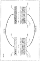
- Figure 8 illustrates the function of the system in enabling a remote device 8.030 to send commands to the alarm system 8.002 via the web server 8.018.
- Communication between the remote device 8.030 and the web server 8.018 can be carried out using an internet compatible format 8.343, such as HTTP.
- the web server can then convert instructions received from the remote device and intended for the alarm system to an intermediate format 8.345, such as IPC (inter-process communication) for forwarding to the keypad bus interface 8.010.
- the keypad bus interface then adapts the instructions to a format suitable for the alarm system 8.347.
- Each communication path can be bi-directional.
- Figure 9 shows the interchange of instructions between a remote device and an alarm system via a web server for remotely arming the alarm system in accordance with an embodiment.
- the remote device sends an arm instruction to the web server in HTTP format.
- the web server first converts the instruction to IPC format and, at 9.364, sends the instruction to the keypad bus interface.
- the keypad bus interface then adapts the instruction to the keypad bus input format suitable for the alarm system and sends the instruction to the alarm system in the keypad bus format.
- the keypad bus format may involve a series of pulses 9.366, 9.368, 9.370, 9.372.
- the alarm system can then send an acknowledgement signal to the keypad bus interface at 9.374.
- the keypad bus interface can convert the acknowledgement signal to IPC format and transmit it to the web server at 9.376.
- the web server can then update the stored screen display which the remote terminal receives at 9.380.
- Reference to a wired network includes optical fibre networks.
- orientation or direction such as “up”, “down”, “vertical”, “horizontal”, “left”, “right” “upright”, “transverse” etc. are not intended to be absolute terms unless the context requires or indicates otherwise.
Claims (9)
- Terminal client (1.000) adapté pour communiquer avec un système d'alarme (1.002) ;
le terminal client (1.000) comprenant :un processeur de terminal client (4.019) ;une mémoire de terminal client (4.056) associée au processeur de terminal client ;une ou plusieurs interfaces de réseau de communication externe (4.015, 4.215, 4.214. 4.018.2) ;au moins une première interface de communication locale (4.026) adaptée pour se connecter à un système d'alarme (1.002) ;dans lequel la mémoire de terminal client comprend un serveur Web (4.018) adapté pour communiquer avec un dispositif distant (1.030) via au moins un réseau de communication externe ;caractérisé en ce que le terminal client est adapté pour convertir des instructions dans un premier format provenant du dispositif distant à un format de système d'alarme pour la réception par le système d'alarme via au moins la première interface de communication locale avec le système d'alarme ; dans lequel le serveur Web (4.018) est adapté pour convertir les instructions dans le premier format à un format intermédiaire et pour envoyer les instructions dans le format intermédiaire à l'interface de communication locale (LCI), et la LCI est adaptée pour convertir les instructions dans le format intermédiaire au format de système d'alarme pour la transmission au système d'alarme (1.002). - Terminal client selon la revendication 1, dans lequel le serveur Web est adapté pour recevoir des informations à partir du système d'alarme (1.002).
- Terminal client selon la revendication 2, dans lequel le serveur Web est adapté pour stocker des informations provenant du système d'alarme (1.002).
- Terminal client selon une quelconque revendication précédente, dans lequel le serveur Web (4.018) est adapté pour envoyer des informations au dispositif distant en réponse à une demande provenant du dispositif distant (1030).
- Terminal client selon une quelconque revendication précédente, dans lequel le serveur Web (4.018) est adapté pour transmettre des informations désignées au dispositif distant (1.030).
- Terminal client selon une quelconque revendication précédente, comprenant en outre une seconde interface de communication avec le système d'alarme (1.002) via laquelle le système d'alarme est adapté pour envoyer des informations au terminal client (1.000).
- Système de transmission d'alarme comprenant un terminal client selon une quelconque revendication précédente et un dispositif distant (1.030) adapté pour communiquer avec le serveur Web (4.018) via au moins un des réseaux de communication externes.
- Procédé d'envoi d'instructions d'un dispositif distant à un système d'alarme (1.002) via un système de transmission d'alarme selon la revendication 7, le procédé comprenant :la connexion du dispositif distant (1.030) sur le serveur Web (4.018) ;l'envoi d'instructions dans un premier format provenant du dispositif distant au serveur Web ;la conversion des instructions dans le premier format à un format de système d'alarme ;l'envoi des instructions dans le format de système d'alarme au système d'alarme (1.002).
- Procédé d'envoi d'instructions selon la revendication 8, comprenant en outre :la conversion des instructions dans le premier format à un format intermédiaire ; etla conversion des instructions dans le format intermédiaire au format de système d'alarme avant l'envoi des instructions dans le format de système d'alarme.
Applications Claiming Priority (1)
| Application Number | Priority Date | Filing Date | Title |
|---|---|---|---|
| US201562220581P | 2015-09-18 | 2015-09-18 |
Publications (2)
| Publication Number | Publication Date |
|---|---|
| EP3144913A1 EP3144913A1 (fr) | 2017-03-22 |
| EP3144913B1 true EP3144913B1 (fr) | 2021-01-13 |
Family
ID=57286195
Family Applications (1)
| Application Number | Title | Priority Date | Filing Date |
|---|---|---|---|
| EP16189064.5A Active EP3144913B1 (fr) | 2015-09-18 | 2016-09-15 | Système, appareil et procédé pour faciliter la communication d'un système d'alarme |
Country Status (2)
| Country | Link |
|---|---|
| US (1) | US10062264B2 (fr) |
| EP (1) | EP3144913B1 (fr) |
Families Citing this family (1)
| Publication number | Priority date | Publication date | Assignee | Title |
|---|---|---|---|---|
| US20210012642A1 (en) | 2019-07-12 | 2021-01-14 | Carrier Corporation | Security system with distributed audio and video sources |
Family Cites Families (74)
| Publication number | Priority date | Publication date | Assignee | Title |
|---|---|---|---|---|
| US5134644A (en) * | 1990-08-17 | 1992-07-28 | Senses International | Data communication device |
| US5956487A (en) | 1996-10-25 | 1999-09-21 | Hewlett-Packard Company | Embedding web access mechanism in an appliance for user interface functions including a web server and web browser |
| AU1823799A (en) | 1997-12-29 | 1999-07-19 | Ameritech Corporation | System and method for home automation and security |
| US7015806B2 (en) * | 1999-07-20 | 2006-03-21 | @Security Broadband Corporation | Distributed monitoring for a video security system |
| US6917288B2 (en) | 1999-09-01 | 2005-07-12 | Nettalon Security Systems, Inc. | Method and apparatus for remotely monitoring a site |
| PL358669A1 (en) | 2000-03-13 | 2004-08-09 | Pittway Corporation | Integrated security and communications system with secure communications link |
| US6640140B1 (en) | 2000-10-10 | 2003-10-28 | Schneider Automation Inc. | PLC executive with integrated web server |
| US6870906B2 (en) | 2001-04-04 | 2005-03-22 | Brian Dawson | Emergency call system using wireless, direct connect and telephone subsystems |
| US7113090B1 (en) | 2001-04-24 | 2006-09-26 | Alarm.Com Incorporated | System and method for connecting security systems to a wireless device |
| US7253728B2 (en) | 2002-07-29 | 2007-08-07 | Uhs Systems Pty Limited | Telemetry system |
| US8813142B2 (en) | 2003-01-31 | 2014-08-19 | Qwest Communications International Inc. | Methods, systems and apparatus for providing video transmissions over multiple media |
| US7467400B1 (en) | 2003-02-14 | 2008-12-16 | S2 Security Corporation | Integrated security system having network enabled access control and interface devices |
| US20040205824A1 (en) | 2003-04-10 | 2004-10-14 | Chic Technology Corp. | Web home security system |
| US7561038B2 (en) * | 2003-07-21 | 2009-07-14 | Uhs Systems Pty Limited | Telemetry system |
| US7761571B2 (en) | 2003-11-25 | 2010-07-20 | Panasonic Corporation | SIP service for home network device and service mobility |
| US20050143863A1 (en) | 2003-12-19 | 2005-06-30 | Margaret Ruane | Building control system field panel having integrated web server |
| US20120066608A1 (en) | 2005-03-16 | 2012-03-15 | Ken Sundermeyer | Control system user interface |
| US10062273B2 (en) * | 2010-09-28 | 2018-08-28 | Icontrol Networks, Inc. | Integrated security system with parallel processing architecture |
| US8963713B2 (en) | 2005-03-16 | 2015-02-24 | Icontrol Networks, Inc. | Integrated security network with security alarm signaling system |
| US20160065414A1 (en) * | 2013-06-27 | 2016-03-03 | Ken Sundermeyer | Control system user interface |
| US9191228B2 (en) * | 2005-03-16 | 2015-11-17 | Icontrol Networks, Inc. | Cross-client sensor user interface in an integrated security network |
| US7440809B2 (en) | 2004-07-14 | 2008-10-21 | York International Corporation | HTML driven embedded controller |
| JP2006048174A (ja) | 2004-07-30 | 2006-02-16 | A・T・Gジャパン株式会社 | ホームセキュリティシステム |
| US7277018B2 (en) | 2004-09-17 | 2007-10-02 | Incident Alert Systems, Llc | Computer-enabled, networked, facility emergency notification, management and alarm system |
| US20060209857A1 (en) * | 2005-03-15 | 2006-09-21 | Bellsouth Intellectual Property Corporation | Broadband home applications gateway/residential gateway systems, methods and computer program products |
| US20060271695A1 (en) * | 2005-05-16 | 2006-11-30 | Electronics Line 3000 Ltd. | System for remote secured operation, monitoring and control of security and other types of events |
| CN101218790A (zh) * | 2005-07-04 | 2008-07-09 | Sk电信股份有限公司 | 家庭网络系统及其控制方法、设置家庭网络系统的住宅网关的方法以及处理家庭网络系统的事件协议的方法 |
| JP4901863B2 (ja) | 2005-07-04 | 2012-03-21 | エスケーテレコム株式会社 | ホームネットワークサービスのための住居用ゲートウェイシステム |
| US7576646B2 (en) | 2005-09-20 | 2009-08-18 | Robert Bosch Gmbh | Method and apparatus for adding wireless devices to a security system |
| US20070142076A1 (en) | 2005-12-15 | 2007-06-21 | Ascom Tateco Ab | Alarm and messaging communications system having wireless network gateway |
| US8214881B2 (en) | 2006-02-10 | 2012-07-03 | Siemens Aktiengesellschaft | Security key with instructions |
| US7746224B2 (en) * | 2006-08-14 | 2010-06-29 | Honeywell International Inc. | Instant messaging applications in security systems |
| DE102006048705A1 (de) | 2006-10-14 | 2008-04-17 | Netgate Security-Produkte Gmbh | Vorrichtung zur Telekommunikation mit in Sicherungsbereichen installierten Alarmvorrichtungen od.dgl. |
| US8576068B2 (en) * | 2006-12-29 | 2013-11-05 | Honeywell International Inc. | Method and system for uploading near-real-time messages to keypad of a security system |
| US7633385B2 (en) | 2007-02-28 | 2009-12-15 | Ucontrol, Inc. | Method and system for communicating with and controlling an alarm system from a remote server |
| US7855635B2 (en) | 2007-02-28 | 2010-12-21 | Ucontrol, Inc. | Method and system for coupling an alarm system to an external network |
| GB2448196A (en) | 2007-05-14 | 2008-10-08 | Serbal Group Ltd | Alerting a community to security problems via SMS |
| US7940673B2 (en) | 2007-06-06 | 2011-05-10 | Veedims, Llc | System for integrating a plurality of modules using a power/data backbone network |
| ATE523002T1 (de) | 2007-12-31 | 2011-09-15 | Schlage Lock Co | Gateway für maschennetzsicherheitssystem und verfahren |
| US20090231120A1 (en) | 2008-03-13 | 2009-09-17 | Chung Donny | Integrated apparatus for medical alarm system |
| CZ2008162A3 (cs) | 2008-03-14 | 2009-09-23 | Barco, S. R. O. | Systém pro zabezpecení budov |
| US8289134B2 (en) * | 2008-08-25 | 2012-10-16 | Robert Bosch Gmbh | Security system and method with automatic language selection |
| US8638211B2 (en) | 2009-04-30 | 2014-01-28 | Icontrol Networks, Inc. | Configurable controller and interface for home SMA, phone and multimedia |
| CN201444343U (zh) | 2009-05-21 | 2010-04-28 | 青岛海尔软件有限公司 | 基于机顶盒的报警系统 |
| KR20110047764A (ko) * | 2009-10-30 | 2011-05-09 | 삼성전자주식회사 | 이동 단말을 이용하여 홈 네트워크 시스템을 제어하기 위한 방법 및 장치 |
| US8508355B2 (en) | 2010-02-23 | 2013-08-13 | Oncam Global, Inc. | Methods and systems for remote management of security systems |
| US8542115B2 (en) | 2010-03-03 | 2013-09-24 | Honeywell International Inc. | Environmental sensor with webserver and email notification |
| US8335596B2 (en) | 2010-07-16 | 2012-12-18 | Verizon Patent And Licensing Inc. | Remote energy management using persistent smart grid network context |
| US8836467B1 (en) | 2010-09-28 | 2014-09-16 | Icontrol Networks, Inc. | Method, system and apparatus for automated reporting of account and sensor zone information to a central station |
| US8519842B2 (en) | 2010-10-14 | 2013-08-27 | Honeywell International Inc. | REST and RSS enabled access control panel |
| US8626210B2 (en) | 2010-11-15 | 2014-01-07 | At&T Intellectual Property I, L.P. | Methods, systems, and products for security systems |
| US8705716B2 (en) | 2011-04-27 | 2014-04-22 | Numerex Corp. | Interactive control of alarm systems by telephone interface using an intermediate gateway |
| US8489065B2 (en) | 2011-05-03 | 2013-07-16 | Robert M Green | Mobile device controller application for any security system |
| EP2933787A1 (fr) | 2011-05-13 | 2015-10-21 | Tattletale Portable Alarm Systems, Inc. | Alarme de consommateur avec bouton silencieux |
| WO2013008252A2 (fr) | 2011-07-08 | 2013-01-17 | Shetty Ravindra K | Système d'automatisation intégré, interopérable et reconfigurable |
| EP2737464A1 (fr) | 2011-07-29 | 2014-06-04 | ADT US Holdings, Inc. | Système et procédé de sécurité |
| WO2013052529A1 (fr) | 2011-10-03 | 2013-04-11 | Numerex Corp. | Procédé et système pour commande de système de sécurité par couplage à distance |
| US8478450B2 (en) | 2011-10-04 | 2013-07-02 | Advanergy, Inc. | Power control system and method |
| US8649883B2 (en) * | 2011-10-04 | 2014-02-11 | Advanergy, Inc. | Power distribution system and method |
| US9749285B2 (en) | 2011-12-08 | 2017-08-29 | Honeywell International Inc. | Connected home control system with auto router port configuration and DDNS registration |
| US20130191660A1 (en) | 2012-01-25 | 2013-07-25 | Honeywell International Inc. | Electrical switch controller with wirelessly addressable web server |
| US9927819B2 (en) | 2012-03-27 | 2018-03-27 | Honeywell International Inc. | Home energy management devices, systems, and methods |
| GB2502075A (en) | 2012-05-14 | 2013-11-20 | Peter James Biggin | Alarm signalling device sending alerts via multiple communications methods to multiple contacts |
| ES2634443T3 (es) | 2012-08-14 | 2017-09-27 | Verisure Sàrl | Un método y un dispositivo para el control de un sistema de seguridad |
| EP2717516A1 (fr) * | 2012-10-04 | 2014-04-09 | Thomson Licensing | Procédé de protection de données partagées entre des dispositifs de réseau local et appareil mettant en 'uvre le procédé |
| WO2014072910A1 (fr) | 2012-11-06 | 2014-05-15 | Innoware A/S | Système d'alarme intelligent avec notification de flux vidéo confirmé par un utilisateur de centre d'appels pour la sécurité publique (psap) combiné à la sécurité des données et à la participation de services publics d'urgence au moyen d'agents de téléphone intelligent |
| US9035763B2 (en) | 2013-03-14 | 2015-05-19 | Comcast Cable Communications, Llc | Processing alarm signals |
| US9485472B2 (en) | 2013-05-13 | 2016-11-01 | Honeywell International Inc. | System and method for enhanced privacy, resource and alert management |
| WO2015013756A1 (fr) * | 2013-08-01 | 2015-02-05 | Uhs Systems Pty Ltd | Amélioration de la connectivité d'une station centrale |
| WO2015021469A2 (fr) | 2013-08-09 | 2015-02-12 | Icontrol Networks Canada Ulc | Système, procédé, et appareil de télésurveillance |
| CN103578240B (zh) | 2013-10-09 | 2015-10-21 | 无锡恺易物联网科技发展有限公司 | 一种基于物联网的安防服务网 |
| CN104618682A (zh) | 2013-11-04 | 2015-05-13 | 南京中兴力维软件有限公司 | 家居移动监控方法及其系统 |
| CN103632480A (zh) | 2013-12-03 | 2014-03-12 | 青岛海尔软件有限公司 | 一种家庭防盗报警系统 |
| CN103632471A (zh) | 2013-12-05 | 2014-03-12 | 青岛海尔软件有限公司 | 新型家庭防盗报警系统 |
-
2016
- 2016-09-15 EP EP16189064.5A patent/EP3144913B1/fr active Active
- 2016-09-16 US US15/268,143 patent/US10062264B2/en active Active
Also Published As
| Publication number | Publication date |
|---|---|
| US10062264B2 (en) | 2018-08-28 |
| EP3144913A1 (fr) | 2017-03-22 |
| US20170084162A1 (en) | 2017-03-23 |
Similar Documents
| Publication | Publication Date | Title |
|---|---|---|
| US11663902B2 (en) | Method and system for providing alternate network access | |
| US20070290830A1 (en) | Remotely monitored security system | |
| US7804403B2 (en) | Security system control module | |
| US7042350B2 (en) | Security messaging system | |
| US20170256157A1 (en) | Communication systems | |
| US20100278224A1 (en) | Wifi interface to dialup modem | |
| EP3028410B1 (fr) | Amélioration de la connectivité d'une station centrale | |
| US20130279413A1 (en) | Communication terminal for an alarm system | |
| EP3144913B1 (fr) | Système, appareil et procédé pour faciliter la communication d'un système d'alarme | |
| JP2017011380A (ja) | 集合用インターホン装置、中継サーバ装置及びネットワーク通信システム | |
| JP2017175225A (ja) | ドアホン制御装置、ドアホンシステム、ドアホン装置及びドアホン制御方法 | |
| JP5273803B2 (ja) | 通信ネットワークシステム、端末設定方法及びip電話機 | |
| JP2009020626A (ja) | 携帯電話による遠隔監視警報システム | |
| JP5067543B2 (ja) | Ip電話システム、子機装置および通信処理プログラム | |
| JP2008136053A (ja) | 遠隔監視制御システム、監視対象制御装置及び通信端末 | |
| JP6145844B2 (ja) | 住宅情報盤、インターホンシステム及び携帯無線端末機用プログラム | |
| JP5246357B2 (ja) | コールセンタシステム及びコールセンタシステムの制御方法 | |
| JP5344717B2 (ja) | 簡易メール通信機能を有する電話システム | |
| GB2465833A (en) | An apparatus for communicating between an alarm device and an alarm gateway over the Public Switched Telephone Network. | |
| GB2469230A (en) | Periodic polling to test the link between an alarm gateway and an alarm interface device. | |
| WO2004062237A2 (fr) | Module de passerelle universelle permettant d'etablir une interface entre une commande de systeme de securite et des dispositifs peripheriques | |
| JP6151584B2 (ja) | 通信方法および通信システム | |
| JP2007135104A (ja) | 遠隔機器 | |
| KR101220033B1 (ko) | 인터넷 전화기 | |
| KR20110012151A (ko) | 긴급 전화 시 주소를 전송해 주는 장치, 인터넷 전화기, ip 공유기 및 전화기의 동작 방법 |
Legal Events
| Date | Code | Title | Description |
|---|---|---|---|
| PUAI | Public reference made under article 153(3) epc to a published international application that has entered the european phase |
Free format text: ORIGINAL CODE: 0009012 |
|
| STAA | Information on the status of an ep patent application or granted ep patent |
Free format text: STATUS: THE APPLICATION HAS BEEN PUBLISHED |
|
| AK | Designated contracting states |
Kind code of ref document: A1 Designated state(s): AL AT BE BG CH CY CZ DE DK EE ES FI FR GB GR HR HU IE IS IT LI LT LU LV MC MK MT NL NO PL PT RO RS SE SI SK SM TR |
|
| AX | Request for extension of the european patent |
Extension state: BA ME |
|
| STAA | Information on the status of an ep patent application or granted ep patent |
Free format text: STATUS: REQUEST FOR EXAMINATION WAS MADE |
|
| 17P | Request for examination filed |
Effective date: 20170919 |
|
| RBV | Designated contracting states (corrected) |
Designated state(s): AL AT BE BG CH CY CZ DE DK EE ES FI FR GB GR HR HU IE IS IT LI LT LU LV MC MK MT NL NO PL PT RO RS SE SI SK SM TR |
|
| RIC1 | Information provided on ipc code assigned before grant |
Ipc: H04L 12/46 20060101ALI20200604BHEP Ipc: H04L 29/08 20060101ALI20200604BHEP Ipc: G08B 25/10 20060101AFI20200604BHEP Ipc: H04L 12/66 20060101ALI20200604BHEP |
|
| GRAP | Despatch of communication of intention to grant a patent |
Free format text: ORIGINAL CODE: EPIDOSNIGR1 |
|
| STAA | Information on the status of an ep patent application or granted ep patent |
Free format text: STATUS: GRANT OF PATENT IS INTENDED |
|
| INTG | Intention to grant announced |
Effective date: 20200728 |
|
| GRAS | Grant fee paid |
Free format text: ORIGINAL CODE: EPIDOSNIGR3 |
|
| GRAA | (expected) grant |
Free format text: ORIGINAL CODE: 0009210 |
|
| STAA | Information on the status of an ep patent application or granted ep patent |
Free format text: STATUS: THE PATENT HAS BEEN GRANTED |
|
| AK | Designated contracting states |
Kind code of ref document: B1 Designated state(s): AL AT BE BG CH CY CZ DE DK EE ES FI FR GB GR HR HU IE IS IT LI LT LU LV MC MK MT NL NO PL PT RO RS SE SI SK SM TR |
|
| REG | Reference to a national code |
Ref country code: GB Ref legal event code: FG4D |
|
| REG | Reference to a national code |
Ref country code: CH Ref legal event code: EP |
|
| REG | Reference to a national code |
Ref country code: DE Ref legal event code: R096 Ref document number: 602016051322 Country of ref document: DE |
|
| REG | Reference to a national code |
Ref country code: IE Ref legal event code: FG4D |
|
| REG | Reference to a national code |
Ref country code: AT Ref legal event code: REF Ref document number: 1355129 Country of ref document: AT Kind code of ref document: T Effective date: 20210215 |
|
| REG | Reference to a national code |
Ref country code: NL Ref legal event code: FP |
|
| REG | Reference to a national code |
Ref country code: AT Ref legal event code: MK05 Ref document number: 1355129 Country of ref document: AT Kind code of ref document: T Effective date: 20210113 |
|
| REG | Reference to a national code |
Ref country code: LT Ref legal event code: MG9D |
|
| PG25 | Lapsed in a contracting state [announced via postgrant information from national office to epo] |
Ref country code: BG Free format text: LAPSE BECAUSE OF FAILURE TO SUBMIT A TRANSLATION OF THE DESCRIPTION OR TO PAY THE FEE WITHIN THE PRESCRIBED TIME-LIMIT Effective date: 20210413 Ref country code: LT Free format text: LAPSE BECAUSE OF FAILURE TO SUBMIT A TRANSLATION OF THE DESCRIPTION OR TO PAY THE FEE WITHIN THE PRESCRIBED TIME-LIMIT Effective date: 20210113 Ref country code: FI Free format text: LAPSE BECAUSE OF FAILURE TO SUBMIT A TRANSLATION OF THE DESCRIPTION OR TO PAY THE FEE WITHIN THE PRESCRIBED TIME-LIMIT Effective date: 20210113 Ref country code: HR Free format text: LAPSE BECAUSE OF FAILURE TO SUBMIT A TRANSLATION OF THE DESCRIPTION OR TO PAY THE FEE WITHIN THE PRESCRIBED TIME-LIMIT Effective date: 20210113 Ref country code: GR Free format text: LAPSE BECAUSE OF FAILURE TO SUBMIT A TRANSLATION OF THE DESCRIPTION OR TO PAY THE FEE WITHIN THE PRESCRIBED TIME-LIMIT Effective date: 20210414 Ref country code: PT Free format text: LAPSE BECAUSE OF FAILURE TO SUBMIT A TRANSLATION OF THE DESCRIPTION OR TO PAY THE FEE WITHIN THE PRESCRIBED TIME-LIMIT Effective date: 20210513 Ref country code: NO Free format text: LAPSE BECAUSE OF FAILURE TO SUBMIT A TRANSLATION OF THE DESCRIPTION OR TO PAY THE FEE WITHIN THE PRESCRIBED TIME-LIMIT Effective date: 20210413 |
|
| PG25 | Lapsed in a contracting state [announced via postgrant information from national office to epo] |
Ref country code: RS Free format text: LAPSE BECAUSE OF FAILURE TO SUBMIT A TRANSLATION OF THE DESCRIPTION OR TO PAY THE FEE WITHIN THE PRESCRIBED TIME-LIMIT Effective date: 20210113 Ref country code: LV Free format text: LAPSE BECAUSE OF FAILURE TO SUBMIT A TRANSLATION OF THE DESCRIPTION OR TO PAY THE FEE WITHIN THE PRESCRIBED TIME-LIMIT Effective date: 20210113 Ref country code: PL Free format text: LAPSE BECAUSE OF FAILURE TO SUBMIT A TRANSLATION OF THE DESCRIPTION OR TO PAY THE FEE WITHIN THE PRESCRIBED TIME-LIMIT Effective date: 20210113 Ref country code: AT Free format text: LAPSE BECAUSE OF FAILURE TO SUBMIT A TRANSLATION OF THE DESCRIPTION OR TO PAY THE FEE WITHIN THE PRESCRIBED TIME-LIMIT Effective date: 20210113 Ref country code: SE Free format text: LAPSE BECAUSE OF FAILURE TO SUBMIT A TRANSLATION OF THE DESCRIPTION OR TO PAY THE FEE WITHIN THE PRESCRIBED TIME-LIMIT Effective date: 20210113 |
|
| PG25 | Lapsed in a contracting state [announced via postgrant information from national office to epo] |
Ref country code: IS Free format text: LAPSE BECAUSE OF FAILURE TO SUBMIT A TRANSLATION OF THE DESCRIPTION OR TO PAY THE FEE WITHIN THE PRESCRIBED TIME-LIMIT Effective date: 20210513 |
|
| REG | Reference to a national code |
Ref country code: DE Ref legal event code: R097 Ref document number: 602016051322 Country of ref document: DE |
|
| PG25 | Lapsed in a contracting state [announced via postgrant information from national office to epo] |
Ref country code: EE Free format text: LAPSE BECAUSE OF FAILURE TO SUBMIT A TRANSLATION OF THE DESCRIPTION OR TO PAY THE FEE WITHIN THE PRESCRIBED TIME-LIMIT Effective date: 20210113 Ref country code: CZ Free format text: LAPSE BECAUSE OF FAILURE TO SUBMIT A TRANSLATION OF THE DESCRIPTION OR TO PAY THE FEE WITHIN THE PRESCRIBED TIME-LIMIT Effective date: 20210113 Ref country code: SM Free format text: LAPSE BECAUSE OF FAILURE TO SUBMIT A TRANSLATION OF THE DESCRIPTION OR TO PAY THE FEE WITHIN THE PRESCRIBED TIME-LIMIT Effective date: 20210113 |
|
| PLBE | No opposition filed within time limit |
Free format text: ORIGINAL CODE: 0009261 |
|
| STAA | Information on the status of an ep patent application or granted ep patent |
Free format text: STATUS: NO OPPOSITION FILED WITHIN TIME LIMIT |
|
| PG25 | Lapsed in a contracting state [announced via postgrant information from national office to epo] |
Ref country code: DK Free format text: LAPSE BECAUSE OF FAILURE TO SUBMIT A TRANSLATION OF THE DESCRIPTION OR TO PAY THE FEE WITHIN THE PRESCRIBED TIME-LIMIT Effective date: 20210113 Ref country code: ES Free format text: LAPSE BECAUSE OF FAILURE TO SUBMIT A TRANSLATION OF THE DESCRIPTION OR TO PAY THE FEE WITHIN THE PRESCRIBED TIME-LIMIT Effective date: 20210113 Ref country code: SK Free format text: LAPSE BECAUSE OF FAILURE TO SUBMIT A TRANSLATION OF THE DESCRIPTION OR TO PAY THE FEE WITHIN THE PRESCRIBED TIME-LIMIT Effective date: 20210113 Ref country code: RO Free format text: LAPSE BECAUSE OF FAILURE TO SUBMIT A TRANSLATION OF THE DESCRIPTION OR TO PAY THE FEE WITHIN THE PRESCRIBED TIME-LIMIT Effective date: 20210113 |
|
| PGFP | Annual fee paid to national office [announced via postgrant information from national office to epo] |
Ref country code: GB Payment date: 20210825 Year of fee payment: 6 |
|
| 26N | No opposition filed |
Effective date: 20211014 |
|
| PG25 | Lapsed in a contracting state [announced via postgrant information from national office to epo] |
Ref country code: AL Free format text: LAPSE BECAUSE OF FAILURE TO SUBMIT A TRANSLATION OF THE DESCRIPTION OR TO PAY THE FEE WITHIN THE PRESCRIBED TIME-LIMIT Effective date: 20210113 |
|
| PG25 | Lapsed in a contracting state [announced via postgrant information from national office to epo] |
Ref country code: SI Free format text: LAPSE BECAUSE OF FAILURE TO SUBMIT A TRANSLATION OF THE DESCRIPTION OR TO PAY THE FEE WITHIN THE PRESCRIBED TIME-LIMIT Effective date: 20210113 |
|
| PG25 | Lapsed in a contracting state [announced via postgrant information from national office to epo] |
Ref country code: IT Free format text: LAPSE BECAUSE OF FAILURE TO SUBMIT A TRANSLATION OF THE DESCRIPTION OR TO PAY THE FEE WITHIN THE PRESCRIBED TIME-LIMIT Effective date: 20210113 |
|
| REG | Reference to a national code |
Ref country code: CH Ref legal event code: PL |
|
| REG | Reference to a national code |
Ref country code: BE Ref legal event code: MM Effective date: 20210930 |
|
| PG25 | Lapsed in a contracting state [announced via postgrant information from national office to epo] |
Ref country code: IS Free format text: LAPSE BECAUSE OF FAILURE TO SUBMIT A TRANSLATION OF THE DESCRIPTION OR TO PAY THE FEE WITHIN THE PRESCRIBED TIME-LIMIT Effective date: 20210513 Ref country code: MC Free format text: LAPSE BECAUSE OF FAILURE TO SUBMIT A TRANSLATION OF THE DESCRIPTION OR TO PAY THE FEE WITHIN THE PRESCRIBED TIME-LIMIT Effective date: 20210113 |
|
| PG25 | Lapsed in a contracting state [announced via postgrant information from national office to epo] |
Ref country code: LU Free format text: LAPSE BECAUSE OF NON-PAYMENT OF DUE FEES Effective date: 20210915 Ref country code: IE Free format text: LAPSE BECAUSE OF NON-PAYMENT OF DUE FEES Effective date: 20210915 Ref country code: BE Free format text: LAPSE BECAUSE OF NON-PAYMENT OF DUE FEES Effective date: 20210930 |
|
| PG25 | Lapsed in a contracting state [announced via postgrant information from national office to epo] |
Ref country code: LI Free format text: LAPSE BECAUSE OF NON-PAYMENT OF DUE FEES Effective date: 20210930 Ref country code: CH Free format text: LAPSE BECAUSE OF NON-PAYMENT OF DUE FEES Effective date: 20210930 |
|
| GBPC | Gb: european patent ceased through non-payment of renewal fee |
Effective date: 20220915 |
|
| PG25 | Lapsed in a contracting state [announced via postgrant information from national office to epo] |
Ref country code: HU Free format text: LAPSE BECAUSE OF FAILURE TO SUBMIT A TRANSLATION OF THE DESCRIPTION OR TO PAY THE FEE WITHIN THE PRESCRIBED TIME-LIMIT; INVALID AB INITIO Effective date: 20160915 |
|
| PG25 | Lapsed in a contracting state [announced via postgrant information from national office to epo] |
Ref country code: CY Free format text: LAPSE BECAUSE OF FAILURE TO SUBMIT A TRANSLATION OF THE DESCRIPTION OR TO PAY THE FEE WITHIN THE PRESCRIBED TIME-LIMIT Effective date: 20210113 |
|
| PGFP | Annual fee paid to national office [announced via postgrant information from national office to epo] |
Ref country code: NL Payment date: 20230822 Year of fee payment: 8 |
|
| PG25 | Lapsed in a contracting state [announced via postgrant information from national office to epo] |
Ref country code: GB Free format text: LAPSE BECAUSE OF NON-PAYMENT OF DUE FEES Effective date: 20220915 |
|
| PGFP | Annual fee paid to national office [announced via postgrant information from national office to epo] |
Ref country code: FR Payment date: 20230822 Year of fee payment: 8 Ref country code: DE Payment date: 20230822 Year of fee payment: 8 |