EP3144586B1 - Modularer beleuchter für extrem breites sichtfeld - Google Patents
Modularer beleuchter für extrem breites sichtfeld Download PDFInfo
- Publication number
- EP3144586B1 EP3144586B1 EP16182180.6A EP16182180A EP3144586B1 EP 3144586 B1 EP3144586 B1 EP 3144586B1 EP 16182180 A EP16182180 A EP 16182180A EP 3144586 B1 EP3144586 B1 EP 3144586B1
- Authority
- EP
- European Patent Office
- Prior art keywords
- light
- elementary unit
- array
- illumination system
- lenses
- Prior art date
- Legal status (The legal status is an assumption and is not a legal conclusion. Google has not performed a legal analysis and makes no representation as to the accuracy of the status listed.)
- Active
Links
- 238000005286 illumination Methods 0.000 claims description 103
- 238000000034 method Methods 0.000 claims description 24
- 238000004519 manufacturing process Methods 0.000 claims description 9
- 230000010287 polarization Effects 0.000 claims description 6
- 238000003491 array Methods 0.000 description 41
- 230000003287 optical effect Effects 0.000 description 21
- 238000003384 imaging method Methods 0.000 description 20
- 230000005855 radiation Effects 0.000 description 16
- 230000005540 biological transmission Effects 0.000 description 11
- 238000010586 diagram Methods 0.000 description 9
- 238000007493 shaping process Methods 0.000 description 8
- 238000000265 homogenisation Methods 0.000 description 6
- 238000000701 chemical imaging Methods 0.000 description 4
- 230000008901 benefit Effects 0.000 description 3
- 239000007787 solid Substances 0.000 description 3
- 230000003595 spectral effect Effects 0.000 description 3
- 238000013461 design Methods 0.000 description 2
- 230000007274 generation of a signal involved in cell-cell signaling Effects 0.000 description 2
- 238000012545 processing Methods 0.000 description 2
- 238000010521 absorption reaction Methods 0.000 description 1
- 230000004075 alteration Effects 0.000 description 1
- 238000013459 approach Methods 0.000 description 1
- 238000004590 computer program Methods 0.000 description 1
- 230000006735 deficit Effects 0.000 description 1
- 230000001419 dependent effect Effects 0.000 description 1
- 238000001514 detection method Methods 0.000 description 1
- 230000000694 effects Effects 0.000 description 1
- 239000000839 emulsion Substances 0.000 description 1
- 230000003993 interaction Effects 0.000 description 1
- 229910044991 metal oxide Inorganic materials 0.000 description 1
- 150000004706 metal oxides Chemical class 0.000 description 1
- 238000012986 modification Methods 0.000 description 1
- 230000004048 modification Effects 0.000 description 1
- 238000012634 optical imaging Methods 0.000 description 1
- 230000003534 oscillatory effect Effects 0.000 description 1
- 229920000642 polymer Polymers 0.000 description 1
- 239000004065 semiconductor Substances 0.000 description 1
- 238000003860 storage Methods 0.000 description 1
- 238000010408 sweeping Methods 0.000 description 1
- 238000009827 uniform distribution Methods 0.000 description 1
Images


Classifications
-
- F—MECHANICAL ENGINEERING; LIGHTING; HEATING; WEAPONS; BLASTING
- F21—LIGHTING
- F21V—FUNCTIONAL FEATURES OR DETAILS OF LIGHTING DEVICES OR SYSTEMS THEREOF; STRUCTURAL COMBINATIONS OF LIGHTING DEVICES WITH OTHER ARTICLES, NOT OTHERWISE PROVIDED FOR
- F21V5/00—Refractors for light sources
- F21V5/007—Array of lenses or refractors for a cluster of light sources, e.g. for arrangement of multiple light sources in one plane
-
- F—MECHANICAL ENGINEERING; LIGHTING; HEATING; WEAPONS; BLASTING
- F21—LIGHTING
- F21S—NON-PORTABLE LIGHTING DEVICES; SYSTEMS THEREOF; VEHICLE LIGHTING DEVICES SPECIALLY ADAPTED FOR VEHICLE EXTERIORS
- F21S8/00—Lighting devices intended for fixed installation
-
- F—MECHANICAL ENGINEERING; LIGHTING; HEATING; WEAPONS; BLASTING
- F21—LIGHTING
- F21V—FUNCTIONAL FEATURES OR DETAILS OF LIGHTING DEVICES OR SYSTEMS THEREOF; STRUCTURAL COMBINATIONS OF LIGHTING DEVICES WITH OTHER ARTICLES, NOT OTHERWISE PROVIDED FOR
- F21V5/00—Refractors for light sources
- F21V5/008—Combination of two or more successive refractors along an optical axis
-
- F—MECHANICAL ENGINEERING; LIGHTING; HEATING; WEAPONS; BLASTING
- F21—LIGHTING
- F21V—FUNCTIONAL FEATURES OR DETAILS OF LIGHTING DEVICES OR SYSTEMS THEREOF; STRUCTURAL COMBINATIONS OF LIGHTING DEVICES WITH OTHER ARTICLES, NOT OTHERWISE PROVIDED FOR
- F21V5/00—Refractors for light sources
- F21V5/04—Refractors for light sources of lens shape
-
- F—MECHANICAL ENGINEERING; LIGHTING; HEATING; WEAPONS; BLASTING
- F21—LIGHTING
- F21V—FUNCTIONAL FEATURES OR DETAILS OF LIGHTING DEVICES OR SYSTEMS THEREOF; STRUCTURAL COMBINATIONS OF LIGHTING DEVICES WITH OTHER ARTICLES, NOT OTHERWISE PROVIDED FOR
- F21V5/00—Refractors for light sources
- F21V5/08—Refractors for light sources producing an asymmetric light distribution
-
- F—MECHANICAL ENGINEERING; LIGHTING; HEATING; WEAPONS; BLASTING
- F21—LIGHTING
- F21V—FUNCTIONAL FEATURES OR DETAILS OF LIGHTING DEVICES OR SYSTEMS THEREOF; STRUCTURAL COMBINATIONS OF LIGHTING DEVICES WITH OTHER ARTICLES, NOT OTHERWISE PROVIDED FOR
- F21V7/00—Reflectors for light sources
- F21V7/0083—Array of reflectors for a cluster of light sources, e.g. arrangement of multiple light sources in one plane
-
- G—PHYSICS
- G01—MEASURING; TESTING
- G01S—RADIO DIRECTION-FINDING; RADIO NAVIGATION; DETERMINING DISTANCE OR VELOCITY BY USE OF RADIO WAVES; LOCATING OR PRESENCE-DETECTING BY USE OF THE REFLECTION OR RERADIATION OF RADIO WAVES; ANALOGOUS ARRANGEMENTS USING OTHER WAVES
- G01S17/00—Systems using the reflection or reradiation of electromagnetic waves other than radio waves, e.g. lidar systems
- G01S17/02—Systems using the reflection of electromagnetic waves other than radio waves
- G01S17/06—Systems determining position data of a target
- G01S17/08—Systems determining position data of a target for measuring distance only
-
- G—PHYSICS
- G01—MEASURING; TESTING
- G01S—RADIO DIRECTION-FINDING; RADIO NAVIGATION; DETERMINING DISTANCE OR VELOCITY BY USE OF RADIO WAVES; LOCATING OR PRESENCE-DETECTING BY USE OF THE REFLECTION OR RERADIATION OF RADIO WAVES; ANALOGOUS ARRANGEMENTS USING OTHER WAVES
- G01S17/00—Systems using the reflection or reradiation of electromagnetic waves other than radio waves, e.g. lidar systems
- G01S17/88—Lidar systems specially adapted for specific applications
- G01S17/89—Lidar systems specially adapted for specific applications for mapping or imaging
- G01S17/894—3D imaging with simultaneous measurement of time-of-flight at a 2D array of receiver pixels, e.g. time-of-flight cameras or flash lidar
-
- G—PHYSICS
- G01—MEASURING; TESTING
- G01S—RADIO DIRECTION-FINDING; RADIO NAVIGATION; DETERMINING DISTANCE OR VELOCITY BY USE OF RADIO WAVES; LOCATING OR PRESENCE-DETECTING BY USE OF THE REFLECTION OR RERADIATION OF RADIO WAVES; ANALOGOUS ARRANGEMENTS USING OTHER WAVES
- G01S7/00—Details of systems according to groups G01S13/00, G01S15/00, G01S17/00
- G01S7/48—Details of systems according to groups G01S13/00, G01S15/00, G01S17/00 of systems according to group G01S17/00
- G01S7/481—Constructional features, e.g. arrangements of optical elements
- G01S7/4814—Constructional features, e.g. arrangements of optical elements of transmitters alone
- G01S7/4815—Constructional features, e.g. arrangements of optical elements of transmitters alone using multiple transmitters
-
- G—PHYSICS
- G01—MEASURING; TESTING
- G01S—RADIO DIRECTION-FINDING; RADIO NAVIGATION; DETERMINING DISTANCE OR VELOCITY BY USE OF RADIO WAVES; LOCATING OR PRESENCE-DETECTING BY USE OF THE REFLECTION OR RERADIATION OF RADIO WAVES; ANALOGOUS ARRANGEMENTS USING OTHER WAVES
- G01S7/00—Details of systems according to groups G01S13/00, G01S15/00, G01S17/00
- G01S7/48—Details of systems according to groups G01S13/00, G01S15/00, G01S17/00 of systems according to group G01S17/00
- G01S7/481—Constructional features, e.g. arrangements of optical elements
- G01S7/4817—Constructional features, e.g. arrangements of optical elements relating to scanning
-
- G—PHYSICS
- G02—OPTICS
- G02B—OPTICAL ELEMENTS, SYSTEMS OR APPARATUS
- G02B19/00—Condensers, e.g. light collectors or similar non-imaging optics
- G02B19/0004—Condensers, e.g. light collectors or similar non-imaging optics characterised by the optical means employed
- G02B19/0009—Condensers, e.g. light collectors or similar non-imaging optics characterised by the optical means employed having refractive surfaces only
- G02B19/0014—Condensers, e.g. light collectors or similar non-imaging optics characterised by the optical means employed having refractive surfaces only at least one surface having optical power
-
- G—PHYSICS
- G02—OPTICS
- G02B—OPTICAL ELEMENTS, SYSTEMS OR APPARATUS
- G02B19/00—Condensers, e.g. light collectors or similar non-imaging optics
- G02B19/0004—Condensers, e.g. light collectors or similar non-imaging optics characterised by the optical means employed
- G02B19/0028—Condensers, e.g. light collectors or similar non-imaging optics characterised by the optical means employed refractive and reflective surfaces, e.g. non-imaging catadioptric systems
-
- G—PHYSICS
- G02—OPTICS
- G02B—OPTICAL ELEMENTS, SYSTEMS OR APPARATUS
- G02B19/00—Condensers, e.g. light collectors or similar non-imaging optics
- G02B19/0033—Condensers, e.g. light collectors or similar non-imaging optics characterised by the use
- G02B19/0047—Condensers, e.g. light collectors or similar non-imaging optics characterised by the use for use with a light source
- G02B19/0052—Condensers, e.g. light collectors or similar non-imaging optics characterised by the use for use with a light source the light source comprising a laser diode
- G02B19/0057—Condensers, e.g. light collectors or similar non-imaging optics characterised by the use for use with a light source the light source comprising a laser diode in the form of a laser diode array, e.g. laser diode bar
-
- G—PHYSICS
- G02—OPTICS
- G02B—OPTICAL ELEMENTS, SYSTEMS OR APPARATUS
- G02B19/00—Condensers, e.g. light collectors or similar non-imaging optics
- G02B19/0033—Condensers, e.g. light collectors or similar non-imaging optics characterised by the use
- G02B19/0047—Condensers, e.g. light collectors or similar non-imaging optics characterised by the use for use with a light source
- G02B19/0061—Condensers, e.g. light collectors or similar non-imaging optics characterised by the use for use with a light source the light source comprising a LED
- G02B19/0066—Condensers, e.g. light collectors or similar non-imaging optics characterised by the use for use with a light source the light source comprising a LED in the form of an LED array
-
- G—PHYSICS
- G02—OPTICS
- G02B—OPTICAL ELEMENTS, SYSTEMS OR APPARATUS
- G02B19/00—Condensers, e.g. light collectors or similar non-imaging optics
- G02B19/0033—Condensers, e.g. light collectors or similar non-imaging optics characterised by the use
- G02B19/0047—Condensers, e.g. light collectors or similar non-imaging optics characterised by the use for use with a light source
- G02B19/0071—Condensers, e.g. light collectors or similar non-imaging optics characterised by the use for use with a light source adapted to illuminate a complete hemisphere or a plane extending 360 degrees around the source
-
- G—PHYSICS
- G02—OPTICS
- G02B—OPTICAL ELEMENTS, SYSTEMS OR APPARATUS
- G02B27/00—Optical systems or apparatus not provided for by any of the groups G02B1/00 - G02B26/00, G02B30/00
- G02B27/09—Beam shaping, e.g. changing the cross-sectional area, not otherwise provided for
- G02B27/0905—Dividing and/or superposing multiple light beams
-
- G—PHYSICS
- G02—OPTICS
- G02B—OPTICAL ELEMENTS, SYSTEMS OR APPARATUS
- G02B27/00—Optical systems or apparatus not provided for by any of the groups G02B1/00 - G02B26/00, G02B30/00
- G02B27/09—Beam shaping, e.g. changing the cross-sectional area, not otherwise provided for
- G02B27/0938—Using specific optical elements
- G02B27/095—Refractive optical elements
- G02B27/0955—Lenses
- G02B27/0961—Lens arrays
-
- G—PHYSICS
- G02—OPTICS
- G02B—OPTICAL ELEMENTS, SYSTEMS OR APPARATUS
- G02B27/00—Optical systems or apparatus not provided for by any of the groups G02B1/00 - G02B26/00, G02B30/00
- G02B27/09—Beam shaping, e.g. changing the cross-sectional area, not otherwise provided for
- G02B27/0938—Using specific optical elements
- G02B27/095—Refractive optical elements
- G02B27/0955—Lenses
- G02B27/0966—Cylindrical lenses
-
- G—PHYSICS
- G02—OPTICS
- G02B—OPTICAL ELEMENTS, SYSTEMS OR APPARATUS
- G02B27/00—Optical systems or apparatus not provided for by any of the groups G02B1/00 - G02B26/00, G02B30/00
- G02B27/30—Collimators
-
- G—PHYSICS
- G02—OPTICS
- G02B—OPTICAL ELEMENTS, SYSTEMS OR APPARATUS
- G02B3/00—Simple or compound lenses
- G02B3/02—Simple or compound lenses with non-spherical faces
- G02B3/04—Simple or compound lenses with non-spherical faces with continuous faces that are rotationally symmetrical but deviate from a true sphere, e.g. so called "aspheric" lenses
-
- H—ELECTRICITY
- H01—ELECTRIC ELEMENTS
- H01L—SEMICONDUCTOR DEVICES NOT COVERED BY CLASS H10
- H01L33/00—Semiconductor devices with at least one potential-jump barrier or surface barrier specially adapted for light emission; Processes or apparatus specially adapted for the manufacture or treatment thereof or of parts thereof; Details thereof
- H01L33/48—Semiconductor devices with at least one potential-jump barrier or surface barrier specially adapted for light emission; Processes or apparatus specially adapted for the manufacture or treatment thereof or of parts thereof; Details thereof characterised by the semiconductor body packages
- H01L33/58—Optical field-shaping elements
-
- F—MECHANICAL ENGINEERING; LIGHTING; HEATING; WEAPONS; BLASTING
- F21—LIGHTING
- F21Y—INDEXING SCHEME ASSOCIATED WITH SUBCLASSES F21K, F21L, F21S and F21V, RELATING TO THE FORM OR THE KIND OF THE LIGHT SOURCES OR OF THE COLOUR OF THE LIGHT EMITTED
- F21Y2115/00—Light-generating elements of semiconductor light sources
- F21Y2115/10—Light-emitting diodes [LED]
-
- F—MECHANICAL ENGINEERING; LIGHTING; HEATING; WEAPONS; BLASTING
- F21—LIGHTING
- F21Y—INDEXING SCHEME ASSOCIATED WITH SUBCLASSES F21K, F21L, F21S and F21V, RELATING TO THE FORM OR THE KIND OF THE LIGHT SOURCES OR OF THE COLOUR OF THE LIGHT EMITTED
- F21Y2115/00—Light-generating elements of semiconductor light sources
- F21Y2115/30—Semiconductor lasers
Definitions
- the subject matter disclosed herein relates generally to illumination of a viewing area for optical imaging systems, and, more particularly, to an illumination system capable of producing a wide beam in excess of ninety degrees and having a high degree of homogeneity.
- US 2012/057345 A1 describes a line-projection apparatus for arrays of diode-laser bar stacks.
- a plurality of collimating arrangements is provided corresponding in number to the number of diode-laser bars for collimating the output radiation of the diode-laser bars in the diode-laser bars stacks in at least the fast-axis direction.
- a first optical arrangement is configured to collect the output radiation beams from all of the diode-laser bar stacks, homogenize and expand the beams in the length direction of the line of radiation and partially overlap the homogenized expanded beams in the length direction of the line of radiation in a first plane at a predetermined distance from the first optical arrangement.
- a second optical arrangement is configured to homogenize and image the partially overlapped and expanded beams in a second plane at a predetermined distance from the second optical arrangement to form the line of radiation, with the homogenizing and imaging being arranged such that the line of radiation has an about uniform distribution of intensity along the length thereof.
- an illumination system comprising an array of light sources; one or more catadioptric lenses arranged to collect light from the array of light sources; a first array of lenses arranged in a first row that is substantially perpendicular to an optical path of light from the one or more catadioptric lenses; a second array of lenses arranged in a second row that is substantially parallel to the first row and substantially perpendicular to the optical path; and an output lens arranged to collect light from the second array of lenses.
- one or more examples not falling within the scope of the appended claims provide a method for producing a beam of light, comprising generating light by a linear array of light sources; collimating the light by one or more catadioptric lenses to yield first collimated light; homogenizing the first collimated light in a tangential plane by two cylindrical lens arrays set in tandem to one another to yield homogenized light; and collimating the homogenized light in a sagittal plane by a cylindrical lens set perpendicular to the two cylindrical lens arrays to yield second collimated light.
- one or more embodiments provide a method for producing a beam of light, comprising generating light by a two-dimensional array of light sources; collimating the light by one or more catadioptric lenses to yield first collimated light; homogenizing the first collimated light in a tangential plane by two spherical lens arrays set in tandem to one another to yield homogenized light; and collimating the homogenized light in a the tangential plane and a sagittal plane by a spherical lens.
- the term "or” is intended to mean an inclusive “or” rather than an exclusive “or.” That is, unless specified otherwise, or clear from the context, the phrase “X employs A or B” is intended to mean any of the natural inclusive permutations. That is, the phrase “X employs A or B” is satisfied by any of the following instances: X employs A; X employs B; or X employs both A and B.
- the articles “a” and “an” as used in this application and the appended claims should generally be construed to mean “one or more” unless specified otherwise or clear from the context to be directed to a singular form.
- a “set” in the subject disclosure includes one or more elements or entities.
- a set of controllers includes one or more controllers; a set of data resources includes one or more data resources; etc.
- group refers to a collection of one or more entities; e.g., a group of nodes refers to one or more nodes.
- VCSEL Vertical Cavity Surface Emitting Laser
- FIG. 1 is a diagram illustrating capture of an image by an example, non-limiting illumination and imaging system 100, which comprises an illuminator 102 and an imaging system 118.
- Illuminator 102 emits light 104 into a viewing area to be imaged. Portions of the emitted light that are incident on solid objects and surfaces within the field of view - such as solid bodies 108, 110, and 112 and wall 106 - are scattered by the illuminated objects and surfaces as scattered rays 114.
- Subsets of the scattered rays 116 are received and collected by the imaging system 118, and image capturing components within the imaging system 118 (e.g., a photodiode array, a charged-coupled device, a complimentary metal-oxide semiconductor, photographic film or emulsion, etc.) record the rays 116 reflected from the objects and surfaces as an image (or as a set of point cloud data in the case of three-dimensional imaging systems).
- image capturing components within the imaging system 118 e.g., a photodiode array, a charged-coupled device, a complimentary metal-oxide semiconductor, photographic film or emulsion, etc.
- Illuminator 102 and imaging system 118 can be, for example, components of a commercial camera or a more specialized camera such as a multi-spectral or hyper-spectral imaging camera.
- Imaging system 100 may also be components of a time-of-flight (TOF) camera (also known as a three-dimensional image sensor) capable of generating distance information for points within the viewing field.
- TOF time-of-flight
- Illumination systems are typically designed to suit the requirements of a particular type of camera or imaging system. For example, commercial cameras are equipped with a relatively simple flash illuminator to compensate for a deficit of ambient light under dark conditions. Multi-spectral and hyper-spectral imaging systems employ more specialized cameras designed to capture image information at specific electromagnetic frequencies, and therefore use illumination systems that generate light customized for the specific spectral ranges required. With the advent of solid-state illumination sources, such as lasers, VCSELs, and light-emitting diodes (LEDs), which are capable of emitting light at narrow spectral bands, illumination systems are capable of illuminating a viewing space with light directed to specific defined wavelengths. Designers of illumination systems often seek to provide illumination across the spectral ranges required by the imaging application while minimizing the effects of background radiation using compatible bandpass filters.
- solid-state illumination sources such as lasers, VCSELs, and light-emitting diodes (LEDs)
- FIG. 2 is a diagram of an example illumination system 202.
- a given illumination system 202 can comprise a light source 204 - e.g., an LED, a laser (e.g., a vertical-cavity surface-emitting laser, or VCSEL), or other type of source - that generates and emits light 208, and optical components 206 that collect, collimate, and direct the light from the source 204 to the viewing field as a processed beam 210.
- the delivery efficiency of a given illumination system - that is, the percentage of light generated by the source 204 that is ultimately delivered to the viewing field - can be described as the product of the collection efficiency and the transmission efficiency of the system.
- the collection efficiency describes the percentage of light 208 emitted by the source 204 that is collected by the optical components 206 (e.g., by a collection lens) for further optical processing and transmission.
- the transmission efficiency describes the percentage of the collected light that is conserved during transmission of the collected light through the optical path of the optical components 206; that is, the percentage of collected light that is not lost through vignetting, reflection, scattering, or absorption during transmission through the illumination system.
- the delivery efficiency is also at least partially a function of the étendue of the source 204 (or its Lagrange invariant), which is a product of the area of the source 204 and the solid angle at which the source projects its light beam.
- One or more embodiments of the present disclosure provide a modular illumination system that can illuminate a wide field of view (e.g., in excess of 90 degrees) while maintaining a high collection efficiency and transmission, as well as a high degree of homogeneity (e.g., in excess of 80%), across the beam's irradiance profile.
- the high collection efficiency also yields a corresponding high delivery efficiency.
- the elementary unit of the illumination system can comprise a solid-state radiant source - such as an array of LEDs, VCSELs, or lasers - and a number of powered elements that cast light from the source to the field of view with a high collection efficiency. Any illuminated area features are limited by the source étendue, or the Lagrange invariant thereof.
- FIG. 3 is an illustration of an elementary unit 300 for an example illumination system that uses surface-emitting LEDs as the light sources.
- the light source comprises four LED dies 306, or four arrays of LED dies, mounted on a printed circuit board 310.
- each surface-emitting LED has an étendue of at least 2 mm 2 ⁇ sr.
- the radiation emitted by these LED dies is collimated (made more parallel) by four catadioptric lenses 308 comprising both reflective and refractive properties.
- the collimated light from the catadioptric lenses 308 is then homogenized in the tangential plane by two cylindrical lens arrays 304a and 304b set in tandem to one another.
- Each of the cylindrical lens arrays 304a and 304b comprises a series of parallel cylindrical lenses arranged in a row that is substantially perpendicular to the optical path of the collimated light from the catadioptric lenses 308.
- the cylindrical lens arrays 304a and 304b substantially homogenize or normalize the light's power profile to render the irradiance of the beam more uniform across the beam's profile.
- the configuration depicted in FIG. 3 can homogenize the illumination of the viewing field to at least 85%.
- a cylindrical output lens 302 set perpendicularly to the lens arrays 304a and 304b is used to further collimate the illumination beam in the sagittal plane.
- the cylindrical output lens 302 is set such that its axis is perpendicular or substantially perpendicular to the axes of the cylindrical lenses comprising the two cylindrical lens arrays 304a and 304b.
- the collection efficiency of the elementary unit 300 depicted in FIG. 3 is at least 80%.
- FIG. 4 illustrates a top view and a side view of a beam 404 projected by an illumination system 402 comprising elementary unit 300.
- the elementary unit 300 can illuminate a field of view of approximately 4 x 100 degrees (it is to be understood that "top view” and “side view” designations in FIG. 4 are arbitrary, and that the directions of view depend on the orientation of the illumination system within a given context).
- the linear LED array, the cylindrical lens arrays 304a and 304b, and the cylindrical output lens 302 yield a wide and substantially linear illumination field.
- Such linear beams are suitable, for example, in scanning-type imaging systems that collect image data by sweeping a light beam across the viewing area in an oscillatory manner to collect line-wise image data, or that project their beams into a viewing field and collect image information for objects or printed symbols that pass through the linear beam.
- the source has a smaller étendue than that of an LED, such as laser, laser array or VCSEL
- the angle of vertical (or sagittal) expansion can be substantially smaller than 4 degrees.
- FIG. 3 depicts elementary unit 300 as comprising surface-emitting LED dies as the light source
- some examples may use an array of lasers (e.g., a VCSEL array or other laser source) as an alternative to LED dies.
- a VCSEL array or other laser source e.g., a VCSEL array or other laser source
- Example elementary units that incorporate VCSELs as the light source will be described in more detail below in connection with FIGs. 10-13 .
- the laser source may have an étendue of approximately 10 -6 mm 2 ⁇ sr, with a light collection efficiency of almost 100%.
- the catadioptric lenses may be replaced by simple collimating lenses.
- Other types of finite light sources may also be used without departing from the scope of one or more examples of this disclosure.
- the two lens arrays may be replaced by other means of beam homogenization.
- a set of aspherical lenses or a set of aspherical surfaces may be used instead of the two lens arrays to homogenize the light beams.
- the homogenization can be accomplished by a light shaping diffuser.
- the light source of elementary unit 300 may be configured to emit a constant beam of light, or may be configured to emit a pulsed or modulated light beam.
- a pulsed light beam may be appropriate, for example, for use in TOF cameras that measure the distance of an object or surface from the camera based on the time that elapses between transmission of a light pulse and detection of the reflected pulse at the camera (or based on the phase difference between a transmitted pulse and a received pulse).
- the light source may be modulated by a signal generation component in order to modulate a defined signal onto the light beam (e.g., a continuous tone signal, a pulsed modulation, or other signal).
- the signal generation component may modulate the light beam by modulating the driving current of the light source. Modulating the light emitted by the source using a known signal can allow the reflected light to be recognized and differentiated from ambient light by an image processing application executed by the imaging system.
- FIG. 5 depicts another example illumination system comprising two elementary units - elementary unit 300a and elementary unit 300b - similar in configuration to elementary unit 300.
- a first elementary unit comprises four LED dies 506a and corresponding catadioptric lenses 508a, two cylindrical lens arrays 504a and 504b set in tandem to one another for homogenizing the collimated light from the catadioptric lenses 508a in the tangential plane, and a cylindrical lens 502a set perpendicularly to the lens arrays 504a and 504b for collimate the light from the lens arrays 504a and 504b in the sagittal plane.
- a similar second elementary unit is abutted to the first elementary unit, oriented at approximately -90 degrees relative to the first elementary unit.
- the second elementary unit comprises four LED dies 506b, catadioptric lenses 508b, two cylindrical lens arrays 504c and 504d, and a cylindrical lens 502b.
- FIG. 6 illustrates projection of a combined beam 604 by an illumination system 602 comprising two elementary units 300a and 300b oriented as shown in FIG. 5 .
- the combined beam comprises the two individual beams (identified by different shadings in FIG. 6 ) projected by the respective elementary units 300a and 300b through a window 606 of the illumination system 602, yielding a wider illumination field relative to the single elementary unit configuration of FIG. 3 (the side view of the illumination projected by illumination system 602, which is similar to the side view depicted in FIG. 4 , is omitted from FIG. 6 ).
- the configuration depicted in FIG. 5 can yield an illumination field of approximately 4x190 degrees, as shown in FIG. 6 .
- the LED dies can be replaced by another type of light source, such as a laser, without departing from the scope of this disclosure.
- FIG. 7 is a graph plotting the calculated irradiance of the illumination system depicted in FIGs. 5 and 6 at a distance of one meter from the illumination system 602.
- the illumination system exhibits approximately 85% collection efficiency, as well as approximately 85% homogeneity.
- Line 702a represents the irradiance calculated for elementary unit 1 (covering a first range of the viewing field illuminated by elementary unit 1)
- line 702b represents the irradiance calculated for elementary unit 2 (covering a second range of the viewing field illuminated by elementary unit 2).
- Line 704 represents the combined irradiance calculated for the illumination system 602 across the entire illumination field.
- FIG. 8 depicts another example illumination system comprising three elementary units 300a, 300b, and 300c, each having a configuration similar to elementary unit 300.
- the third elementary unit 300c is abutted to the second elementary unit 300b, oriented at -90 degrees relative to the second elementary unit.
- FIG. 9 illustrates projection of a combined beam 904 by an illumination system 902 comprising the three elementary units 300a, 300b, and 300c oriented as shown in FIG. 8 , which project the combined beam through a window 906 of the illumination system 902.
- This configuration yields an illumination field of approximately 4 x 270 degrees.
- a fourth elementary unit can be added to the first three elementary units 300a, 300b, and 300c in a like manner, oriented -90 degrees relative to the third elementary unit 300c (i.e., 180 degrees relative to the second elementary unit 300b). This configuration yields an illumination field of 4x360 degrees.
- the example configurations illustrated in FIGs. 3 , 5 , and 8 employ linear LED arrays and cylindrical lenses to yield a substantially linear beam having a wide field of view.
- the elementary unit(s) can be configured to project an area beam rather than a linear beam. This can be achieved by expanding the array of LED dies 306 from a linear array to an area array - e.g., a two-dimensional array comprising both rows and columns of LEDs - and by replacing the cylindrical lenses of arrays 304a and 304b and cylindrical lens 302 with spherical lenses, thereby extending the sagittal field of illumination.
- the source can comprise a 4x4 array of LED dies.
- the radiation emitted by this area array of LED dies is collimated by a corresponding 4x4 area array of catadioptric lenses, and homogenized in both the sagittal and tangential planes by two spherical lens arrays set in tandem to one another (replacing the cylindrical lens arrays 304a and 304b of FIG. 3 ).
- a spherical output lens - replacing cylindrical output lens 302 of FIG. 3 - is used to further collimate the illumination beam in both the sagittal and tangential planes.
- This configuration yields a field of view of approximately 95x95 degrees (compared with the 4x95 field of view produced by the linear configuration of FIG. 3 ).
- the width of the area beam produced by the area elementary unit can be widened by adding additional elementary units.
- abutting two area elementary units together oriented at 90 degrees relative to one another can yield an illumination field of approximately 95x190 degrees.
- a three-unit illumination system can comprise three area elementary units abutted together, each unit oriented at 90 degrees relative to an adjacent unit (similar to the arrangement of linear elementary units depicted in FIG. 8 ). This three-unit configuration can yield an illumination field of approximately 95x270 degrees.
- a full 95x360 degree illumination field can be projected using a four-unit illumination system comprising four area elementary units abutted to one another, with each elementary unit oriented at 90 degrees relative to an adjacent elementary unit.
- FIG. 10A depicts two three-dimensional views of an elementary unit 1000 for an illumination system that uses VCSELs as the light sources.
- the light source comprises three VCSEL dies 1008 mounted on a printed circuit board 1010.
- each surface-emitting VCSEL has an étendue of typically 0.1 mm 2 ⁇ sr. Radiation emitted by the VCSELs is collimated in the tangential plane and expanded in the sagittal plane by three biconic lenses 1006.
- the radiation is then diffused by a light shaping diffuser 1004, attributing the radiation an azimuthal expanse of approximately 100 degrees, while homogenizing the beam irradiance.
- the configuration depicted in FIG. 10A can homogenize the illumination of the viewing field to at least 85%.
- a cylindrical output lens 1002 set perpendicularly to the VCSEL arrays 1008 is used to collimate the illumination beam in the sagittal plane.
- the transmission efficiency of the elementary unit 1000 depicted in FIG. 10A is at least 80%.
- FIG. 10B A top view of the elementary unit 1000 is shown in FIG. 10B .
- VCSELs 1008 are mounted on a printed circuit board (PCB) 1010.
- PCB printed circuit board
- radiation emitted by the VCSELs 1008 and represented by the rays 1012 is collimated in the tangential plane and expanded in the sagittal plane by three biconic lenses 1006.
- the radiation is then diffused by a light shaping diffuser 1004, attributing the radiation an azimuthal expanse of approximately 100 degrees, while homogenizing the beam irradiance.
- the cylindrical Fresnel output lens 1002 is bent and set perpendicularly to the VCSEL arrays 1008.
- Lens 1002 has no power in the tangential plane and is used to collimate the illumination beam in the sagittal plane.
- FIG. 10C A side view of elementary unit 1000 is shown in FIG. 10C .
- Fresnel lens 1002 An advantage of the Fresnel lens 1002 is that it is thin and can be mass produced at low cost. Fresnel lens 1002 can be made of an optical polymer, allowing the lens 1002 be bent as shown in FIGs. 10A-10C .
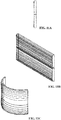
- FIG. 11A illustrates a profile view of an example Fresnel lens.
- FIG. 11B illustrates a cylindrical Fresnel lens.
- FIG. 11C illustrates a bent cylindrical Fresnel lens.
- FIGs. 12A and 12B are plots of the calculated radiance in angular space of the illumination system using VCSELs depicted in FIGs. 10A-10C at a distance of five meters from the illumination system.
- the illumination system exhibits approximately over 80% transmission efficiency, as well as approximately 85% homogeneity.
- FIG. 12A represents the radiance calculated in the tangential angular space spanning an angle of 100 degrees (within the magnitude of 85%), while FIG. 12B represents the radiance calculated in the sagittal angular space spanning an angle of 2.5 degrees (within full width at half maximum, or FWHM).
- additional elementary units using VCSELs can be combined in a modular fashion, similar to the LED-based elementary units described above.
- a first elementary unit comprising three VCSELs 1008 (as shown in FIG. 10B ), corresponding biconic lenses 1006, a light shaping diffuser 1004, and a cylindrical lens 1002
- a second similar unit can be abutted at an azimuthal angle of approximately 90 degrees.
- the resulting combined illumination system radiates to an angular space of approximately 2x190 degrees.
- the two elemental units may radiate at a like wavelength in some embodiments, or at dissimilar wavelengths in other embodiments.
- two elementary units may radiate unpolarized light in some embodiments, or polarized light at similar state of polarization in other embodiments, or polarized light at dissimilar state of polarization in yet other embodiments.
- FIG. 13 is a three-dimensional view depicting three elementary units 1302, 1304, and 1306 that are combined forming an illumination system that radiates to an angular space of approximately 2x280 degrees.
- the three elementary units may radiate at a like wavelength in some embodiments, or at dissimilar wavelengths in other embodiments.
- the elementary units may radiate unpolarized light in some embodiments, or polarized light at similar state of polarization in other embodiments, or polarized light at dissimilar state of polarization in yet other embodiments.
- FIG. 13 depicts the elementary units 1302, 1304, and 1306 in conjunction with an imaging lens 858.
- the configurations illustrated in FIGs. 10A-10C and 13 employ VCSELs and cylindrical lenses to yield a substantially linear beam having a wide field of view.
- the elementary unit(s) can be configured to project an area beam rather than a linear beam. This can be achieved by expanding the array of VCSELs 1008 from a linear array to an area array - e.g., a two-dimensional array comprising both rows and columns of VCSELs, noting that each VCSEL is an array in and of itself - and by replacing the biconic lenses of 1006 and cylindrical lens 1002 with spherical lenses, thereby extending the sagittal field of illumination.
- the source can comprise a 4x4 array of VCSELs.
- Radiation emitted by the VCSELs is collimated by corresponding 4x4 array of lenses, and homogenized by a light shaping diffuser.
- a spherical output lens - replacing cylindrical output lens 1002 of FIG. 10A - is used to further collimate the illumination beam in both the sagittal and tangential planes. This configuration yields a field of view of approximately 100x100 degrees (compared with the 2x100 field of view produced by the linear configuration of FIG. 10A ).
- the width of the area beam produced by the area elementary unit can be widened by adding additional elementary units.
- abutting two area elementary units together oriented at approximately 90 degrees relative to one another can yield an illumination field of approximately 100x190 degrees.
- a three-unit embodiment can comprise three area elementary units abutted together, each unit oriented at approximately 90 degrees relative to an adjacent unit (similar to the arrangement of linear elementary units depicted in FIG. 13 ). This three-unit configuration can yield an illumination field of approximately 100x280 degrees.
- a full 100x360 degree illumination field can be projected using a four-unit embodiment comprising four area elementary units abutted to one another, with each elementary unit oriented at approximately 90 degrees relative to an adjacent elementary unit.
- FIGs 14-18 illustrate various methodologies in accordance with one or more embodiments and examples of the subject application. While, for purposes of simplicity of explanation, the one or more methodologies shown herein are shown and described as a series of acts, it is to be understood and appreciated that the subject innovation is not limited by the order of acts, as some acts may, in accordance therewith, occur in a different order and/or concurrently with other acts from that shown and described herein. For example, those skilled in the art will understand and appreciate that a methodology could alternatively be represented as a series of interrelated states or events, such as in a state diagram. Moreover, not all illustrated acts may be required to implement a methodology in accordance with the innovation.
- interaction diagram(s) may represent methodologies, or methods, in accordance with the subject disclosure when disparate entities enact disparate portions of the methodologies. Further yet, two or more of the disclosed methods can be implemented in combination with each other, to accomplish one or more features or advantages described herein.
- FIG. 14 illustrates an example methodology 1400 for generating a highly homogenized linear beam of light (e.g., in connection with illuminating a field of view to facilitate accurate collection of image data by an imaging system) having a wide illumination field while maintaining a high collection efficiency.
- light is generated using an LED array or laser light source.
- the light source may comprise, for example, a linear array of LED dies or laser light sources.
- light generated at step 1404 is collimated using one or more catadioptric lenses.
- a catadioptric lens can be associated with each LED to collect and collimate the light generated by that LED.
- light from the catadioptric lenses is substantially homogenized in the tangential plane using two cylindrical lens arrays set in tandem to one another.
- light from the cylindrical lens arrays is collimated in the sagittal plane using a cylindrical lens set perpendicular to the cylindrical lens arrays.
- FIG. 15 illustrates a methodology 1500 for generating a highly homogenized linear beam of light (e.g., in connection with illuminating a field of view to facilitate accurate collection of image data by an imaging system) having a wide illumination field while maintaining a high collection efficiency using VCSELs as a source of the illumination.
- light is generated using VCSELs.
- light generated at step 1502 is collimated using one or more biconic lenses.
- light from the biconic lenses is substantially homogenized in the tangential plane using a light shaping diffuser.
- light from the biconic lens arrays is collimated in the sagittal plane using a cylindrical lens set perpendicular to the biconic lens arrays.
- FIG. 16 illustrates an example methodology 1600 for generating a highly homogenized area beam of light (e.g., in connection with illuminating a field of view to facilitate accurate collection of image data by an imaging system) having a wide illumination field while maintaining a high collection efficiency.
- light is generated using an LED array, VCSELs, or laser light source.
- the light source may comprise, for example, a two-dimensional array of LED dies.
- light generated at step 1604 is collimated using one or more catadioptric lenses (or biconic lenses in examples using VCSELs).
- a catadioptric lens can be associated with each LED to collect and collimate the light generated by that LED.
- light from the catadioptric lenses is substantially homogenized in the tangential plane using two spherical lens arrays set in tandem to one another.
- light from the spherical lens arrays is collimated in the sagittal and tangential planes using a spherical lens.
- light from the biconic lenses is substantially homogenized using a light shaping diffuser.
- the light is collimated in the sagittal and tangential planes using a spherical lens.
- FIG. 17 illustrates an example methodology 1700 for manufacturing a modular illumination system capable of projecting a linear light beam having a wide field of view and a high level of homogenization across the beam's irradiance profile.
- a set of catadioptric lenses or biconic lenses in some examples
- the light emitting elements may comprise, for example, LEDs of a linear LED die array, VCSELs, or a laser-based light source.
- two cylindrical lens arrays are placed in the optical path of the collimated light from the catadioptric lenses.
- Each of the cylindrical lens arrays comprises a set of parallel cylindrical lenses placed in a row that is substantially perpendicular to the optical path of the collimated light
- the cylindrical lens arrays at 1704 can be replaced by a light shaping diffuser.
- a cylindrical lens is placed in the optical path of light from the two cylindrical lens arrays such that the axis of the cylindrical lens is oriented substantially perpendicular to the axes of the cylindrical lenses comprising the two cylindrical lens arrays (or biconic lenses in some examples).
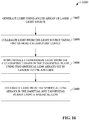
- FIG. 18 illustrates an example methodology 1800 for manufacturing an a modular illumination system capable of projecting an area light beam having a wide field of view and a high level of homogenization across the beam's irradiance profile.
- a set of catadioptric lenses are arranged to collect and collimate light from respective light emitting elements of a two-dimensional array of light emitting elements.
- the light emitting elements may comprise, for example, LEDs of a two-dimensional LED die array, VCSELs, or laser-based light sources.
- two spherical lens arrays are placed in the optical path of the collimated light that radiates from the catadioptric lenses (or biconic lenses in some examples ).
- Each of the spherical lens arrays comprises a set of spherical lenses placed in a row that is substantially perpendicular to the optical path of the collimated light from the catadioptric lenses (or biconic lenses in some examples).
- a spherical lens is placed in the optical path of light that radiates from the two spherical lens arrays.
- the terms (including a reference to a "means") used to describe such components are intended to correspond, unless otherwise indicated, to any component which performs the specified function of the described component (e.g., a functional equivalent), even though not structurally equivalent to the disclosed structure, which performs the function in the herein illustrated exemplary aspects of the disclosed subject matter.
- the disclosed subject matter includes a system as well as a computer-readable medium having computer-executable instructions for performing the acts and/or events of the various methods of the disclosed subject matter.
- exemplary is used to mean serving as an example, instance, or illustration. Any aspect or design described herein as "exemplary” is not necessarily to be construed as preferred or advantageous over other aspects or designs. Rather, use of the word exemplary is intended to present concepts in a concrete fashion.
- Computer readable media can include but are not limited to magnetic storage devices (e.g., hard disk, floppy disk, magnetic strips...), optical disks [e.g., compact disk (CD), digital versatile disk (DVD)...], smart cards, and flash memory devices (e.g., card, stick, key drive).
- magnetic storage devices e.g., hard disk, floppy disk, magnetic strips
- optical disks e.g., compact disk (CD), digital versatile disk (DVD)...
- smart cards e.g., card, stick, key drive
Claims (7)
- Verfahren zur Erzeugung eines Lichtstrahls, mit
Erzeugen (1502) von Licht mittels eines Array aus oberflächenemittierenden Lasern mit vertikaler Kavität, VCSEL;
Kollimieren (1504) des Lichts in einer Tangentialebene und Aufweiten des Lichts in einer Sagittalebene durch eine oder mehrere bikonische Linsen, so dass erstes kollimiertes Licht erhalten wird;
Verteilen und Homogenisieren (1506) des ersten kollimierten Lichts derart, dass homogenisiertes Licht erhalten wird, mit Verteilen und Homogenisieren des ersten kollimierten Lichts unter Anwendung einer Diffusereinheit; und
Kollimieren (1508) des homogenisierten Lichts in einer Sagittalebene durch eine Zylinderlinse, wobei das Kollimieren des homogenisierten Lichts unter Anwendung einer Fresnel-Linse erfolgt. - Verfahren nach Anspruch 1, wobei das Kollimieren umfasst: Kollimieren des Lichts unter Anwendung von drei bikonischen Linsen.
- Beleuchtungssystem, mit:einem Array aus oberflächenemittierenden Lasern mit vertikaler Kavität, VCSEL (1008);einer oder mehreren bikonischen Linsen (1006), die ausgebildet sind, Licht, das von dem VSCEL-Array ausgesendet wird, in einer Tangentialebene zu kollimieren und das Licht in einer Sagittalebene aufzuweiten, so dass erstes kollimiertes Licht erhalten wird;einer Diffusereinheit (1004), die ausgebildet ist, das erste kollimierte Licht zu verteilen und zu homogenisieren, sodass homogenisiertes Licht erhalten wird; undeiner zylindrischen Fresnel-Linse (1002), die ausgebildet ist, das homogenisierte Licht in einer Sagittalebene zu kollimieren.
- Beleuchtungssystem nach Anspruch 3, wobei eine erste Basiseinheit (1302) das Array aus oberflächenemittierenden Lasern mit vertikaler Kavität, VCSEL, die eine oder die mehreren bikonischen Linsen, die Diffusereinheit und die zylindrische Fresnel-Linse aufweist, und
ferner mit:einer zweiten Basiseinheit (1304), die aufweist:ein zweites Array aus oberflächenemittierenden Lasern mit vertikaler Kavität, VCSEL;eine oder mehrere zweite bikonische Linsen, die ausgebildet sind, Licht, das von dem zweiten VSCEL-Array ausgesendet wird, in einer Tangentialebene zu kollimieren und das Licht in einer Sagittalebene aufzuweiten, um zweites kollimiertes Licht zu erhalten;eine zweite Diffusereinheit, die ausgebildet, das zweite kollimierte Licht zu verteilen und zu homogenisieren, so dass zweites homogenisiertes Licht erhalten wird; undeine zweite zylindrische Fresnel-Linse, die ausgebildet ist, das zweite homogenisierte Licht in einer Sagittalebene zu kollimieren,wobei die zweite Basiseinheit unter ungefähr neunzig Grad zu der ersten Basiseinheit orientiert ist. - Beleuchtungssystem nach Anspruch 4, wobei die erste Basiseinheit und die zweite Basiseinheit ausgebildet sind, Licht mit jeweils unterschiedlichen Wellenlängen auszustrahlen oder Licht mit gleicher Wellenlänge auszustrahlen.
- Beleuchtungssystem nach Anspruch 4 oder 5, wobei die erste Basiseinheit und die zweite Basiseinheit ausgebildet sind, unpolarisiertes Licht oder polarisiertes Licht mit einem ähnlichen Polarisationszustand oder polarisiertes Licht mit einem unähnlichen Polarisationszustand auszusenden.
- Beleuchtungssystem nach Anspruch 5 oder 6, das ferner aufweist:
eine dritte Basiseinheit (1308), die aufweist:ein drittes Array aus oberflächenemittierenden Lasern mit vertikaler Kavität, VCSEL;eine oder mehrere dritte bikonische Linsen, die ausgebildet sind, Licht, das von dem dritten VSCEL-Array ausgesendet wird, in einer Tangentialebene zu kollimieren und das Licht in einer Sagittalebene aufzuweiten, so dass drittes kollimiertes Licht erhalten wird;eine dritte Diffusereinheit, die ausgebildet ist, das dritte kollimierte Licht zu verteilen und zu homogenisieren, so dass drittes homogenisiertes Licht erhalten wird; undeine dritte zylindrische Fresnel-Linse, die ausgebildet ist, das dritte homogenisierte Licht in einer Sagittalebene zu kollimieren,wobei die dritte Basiseinheit ungefähr unter neunzig Grad zu der zweiten Basiseinheit orientiert ist.
Applications Claiming Priority (2)
| Application Number | Priority Date | Filing Date | Title |
|---|---|---|---|
| US201562209708P | 2015-08-25 | 2015-08-25 | |
| US14/993,601 US9798126B2 (en) | 2015-08-25 | 2016-01-12 | Modular illuminator for extremely wide field of view |
Publications (3)
| Publication Number | Publication Date |
|---|---|
| EP3144586A2 EP3144586A2 (de) | 2017-03-22 |
| EP3144586A3 EP3144586A3 (de) | 2017-06-21 |
| EP3144586B1 true EP3144586B1 (de) | 2020-11-04 |
Family
ID=56800142
Family Applications (1)
| Application Number | Title | Priority Date | Filing Date |
|---|---|---|---|
| EP16182180.6A Active EP3144586B1 (de) | 2015-08-25 | 2016-08-01 | Modularer beleuchter für extrem breites sichtfeld |
Country Status (3)
| Country | Link |
|---|---|
| US (1) | US9798126B2 (de) |
| EP (1) | EP3144586B1 (de) |
| CN (1) | CN106482032B (de) |
Families Citing this family (19)
| Publication number | Priority date | Publication date | Assignee | Title |
|---|---|---|---|---|
| US10761195B2 (en) | 2016-04-22 | 2020-09-01 | OPSYS Tech Ltd. | Multi-wavelength LIDAR system |
| WO2018004534A1 (en) * | 2016-06-28 | 2018-01-04 | Siemens Industry, Inc. | Optical system for a led signal and wayside led signal |
| US20180180532A1 (en) * | 2016-12-26 | 2018-06-28 | Sheng-Hao Tseng | Multiple wavelength optical system |
| KR102619582B1 (ko) | 2017-03-13 | 2024-01-02 | 옵시스 테크 엘티디 | 눈-안전 스캐닝 lidar 시스템 |
| CN115015883A (zh) | 2017-07-28 | 2022-09-06 | 欧普赛斯技术有限公司 | 具有小角发散度的vcsel阵列lidar发送器 |
| US11802943B2 (en) | 2017-11-15 | 2023-10-31 | OPSYS Tech Ltd. | Noise adaptive solid-state LIDAR system |
| US10436953B2 (en) | 2017-12-01 | 2019-10-08 | Rockwell Automation Technologies Inc. | Arched collimating lens forming a disk-like illumination |
| US10642053B2 (en) * | 2018-03-26 | 2020-05-05 | Simmonds Precision Products, Inc. | Scanned linear illumination of distant objects |
| KR102604050B1 (ko) | 2018-04-01 | 2023-11-22 | 옵시스 테크 엘티디 | 잡음 적응형 솔리드-스테이트 lidar 시스템 |
| DE102018115342A1 (de) * | 2018-06-26 | 2020-01-02 | Tdk Electronics Ag | Bauelement |
| US10609266B2 (en) * | 2018-08-21 | 2020-03-31 | Rockwell Automation Technologies, Inc. | Camera for wide field of view with an arbitrary aspect ratio |
| DE102018120925A1 (de) | 2018-08-28 | 2020-03-05 | Valeo Schalter Und Sensoren Gmbh | Optische Linse für einen Laserscanner für ein Fahrunterstützungssystem |
| JP2022526998A (ja) | 2019-04-09 | 2022-05-27 | オプシス テック リミテッド | レーザ制御を伴うソリッドステートlidar送光機 |
| CN113906316A (zh) | 2019-05-30 | 2022-01-07 | 欧普赛斯技术有限公司 | 使用致动器的眼睛安全的长范围lidar系统 |
| EP3980808A4 (de) | 2019-06-10 | 2023-05-31 | Opsys Tech Ltd. | Augensicheres festkörper-lidar-system mit grosser reichweite |
| KR102089897B1 (ko) * | 2019-07-11 | 2020-03-16 | 한국광기술원 | 다중 배광각 광원 모듈 및 이를 이용한 등명기 |
| US10746905B1 (en) | 2019-09-23 | 2020-08-18 | Rosemount Aerospace Inc. | Optical systems with toroidal fresnel lenses |
| DE102019219585A1 (de) * | 2019-12-13 | 2021-06-17 | Robert Bosch Gmbh | Vorrichtung und Verfahren zur lichtgestützten Abstandsbestimmung, Steuereinheit und Arbeitsvorrichtung |
| DE102019219825A1 (de) | 2019-12-17 | 2021-06-17 | Robert Bosch Gmbh | Sendeeinheit und LIDAR-Vorrichtung mit optischem Homogenisierer |
Family Cites Families (17)
| Publication number | Priority date | Publication date | Assignee | Title |
|---|---|---|---|---|
| US5612821A (en) | 1995-06-15 | 1997-03-18 | United Technologies Corporation | Micro lens system for controlling an optical beam pattern |
| US6830189B2 (en) | 1995-12-18 | 2004-12-14 | Metrologic Instruments, Inc. | Method of and system for producing digital images of objects with subtantially reduced speckle-noise patterns by illuminating said objects with spatially and/or temporally coherent-reduced planar laser illumination |
| US6583937B1 (en) * | 1998-11-30 | 2003-06-24 | Carl-Zeiss Stiftung | Illuminating system of a microlithographic projection exposure arrangement |
| US6433934B1 (en) | 2000-08-11 | 2002-08-13 | Yakov Reznichenko | Illumination system for use in imaging systems |
| JP2002072132A (ja) * | 2000-08-30 | 2002-03-12 | Dainippon Screen Mfg Co Ltd | 照明装置 |
| US7159986B2 (en) * | 2002-05-20 | 2007-01-09 | Swales & Associates, Inc. | Wide field collimator |
| US7619824B2 (en) * | 2003-11-18 | 2009-11-17 | Merlin Technology Limited Liability Company | Variable optical arrays and variable manufacturing methods |
| US7268950B2 (en) * | 2003-11-18 | 2007-09-11 | Merlin Technology Limited Liability Company | Variable optical arrays and variable manufacturing methods |
| JP4616577B2 (ja) | 2004-04-22 | 2011-01-19 | 株式会社日立製作所 | 映像表示装置 |
| JP4843344B2 (ja) * | 2005-03-18 | 2011-12-21 | 株式会社リコー | 照明装置及び画像読取装置 |
| EP2149067A1 (de) | 2007-04-19 | 2010-02-03 | D.V.P. Technologies Ltd. | Abbildungssystem und verfahren zur verwendung beim überwachen eines betrachtungsfeldes |
| GB2469693A (en) * | 2009-04-25 | 2010-10-27 | Optovate Ltd | A controllable light directional distributor for an illumination apparatus |
| US8596823B2 (en) | 2010-09-07 | 2013-12-03 | Coherent, Inc. | Line-projection apparatus for arrays of diode-laser bar stacks |
| NL2008009A (en) * | 2011-02-02 | 2012-08-06 | Asml Netherlands Bv | Illumination system, lithographic apparatus and method. |
| US9551914B2 (en) * | 2011-03-07 | 2017-01-24 | Microsoft Technology Licensing, Llc | Illuminator with refractive optical element |
| JP5724755B2 (ja) | 2011-08-26 | 2015-05-27 | 株式会社リコー | 撮像システム |
| DE102012207931A1 (de) | 2012-01-07 | 2013-07-11 | Johnson Controls Gmbh | Kameraanordnung zur Distanzmessung |
-
2016
- 2016-01-12 US US14/993,601 patent/US9798126B2/en active Active
- 2016-08-01 EP EP16182180.6A patent/EP3144586B1/de active Active
- 2016-08-24 CN CN201610720777.4A patent/CN106482032B/zh active Active
Non-Patent Citations (1)
| Title |
|---|
| None * |
Also Published As
| Publication number | Publication date |
|---|---|
| US9798126B2 (en) | 2017-10-24 |
| EP3144586A3 (de) | 2017-06-21 |
| CN106482032B (zh) | 2020-08-25 |
| CN106482032A (zh) | 2017-03-08 |
| EP3144586A2 (de) | 2017-03-22 |
| US20170059838A1 (en) | 2017-03-02 |
Similar Documents
| Publication | Publication Date | Title |
|---|---|---|
| EP3144586B1 (de) | Modularer beleuchter für extrem breites sichtfeld | |
| JP7442837B2 (ja) | 小角度発散を伴うvcselアレイlidar送信機 | |
| CN108779905B (zh) | 多模式照明模块和相关方法 | |
| CN108604053B (zh) | 编码图案投影仪 | |
| US9273846B1 (en) | Apparatus for producing patterned illumination including at least one array of light sources and at least one array of microlenses | |
| CN104956179A (zh) | 利用折射或反射光的结构化元件从光源阵列生成结构化光场的光学系统 | |
| US10386706B2 (en) | Structured-light projector | |
| US10609266B2 (en) | Camera for wide field of view with an arbitrary aspect ratio | |
| US10754167B2 (en) | Structured-light projector | |
| RU2632254C2 (ru) | Осветительное устройство | |
| EP3492960B1 (de) | Gewölbte kollimationslinse zur formung einer scheibenähnlichen beleuchtung | |
| KR20240054419A (ko) | Vcsel 기반의 패턴 프로젝터 | |
| US20140111619A1 (en) | Device and method for acquiring image | |
| CN112004000A (zh) | 发光装置及应用其的图像采集装置 | |
| CN210109475U (zh) | 3d成像装置 | |
| EP2983033A1 (de) | Laserprojektor zur erzeugung eines lichtstreifens | |
| JP2022074568A (ja) | 拡散素子、投射装置、及び空間認識装置 | |
| CN116893506A (zh) | 用于lidar的扫描仪激光光学器件 | |
| JP2022074585A (ja) | 拡散素子、投射装置、及び空間認識装置 |
Legal Events
| Date | Code | Title | Description |
|---|---|---|---|
| PUAI | Public reference made under article 153(3) epc to a published international application that has entered the european phase |
Free format text: ORIGINAL CODE: 0009012 |
|
| STAA | Information on the status of an ep patent application or granted ep patent |
Free format text: STATUS: THE APPLICATION HAS BEEN PUBLISHED |
|
| AK | Designated contracting states |
Kind code of ref document: A2 Designated state(s): AL AT BE BG CH CY CZ DE DK EE ES FI FR GB GR HR HU IE IS IT LI LT LU LV MC MK MT NL NO PL PT RO RS SE SI SK SM TR |
|
| AX | Request for extension of the european patent |
Extension state: BA ME |
|
| PUAL | Search report despatched |
Free format text: ORIGINAL CODE: 0009013 |
|
| AK | Designated contracting states |
Kind code of ref document: A3 Designated state(s): AL AT BE BG CH CY CZ DE DK EE ES FI FR GB GR HR HU IE IS IT LI LT LU LV MC MK MT NL NO PL PT RO RS SE SI SK SM TR |
|
| AX | Request for extension of the european patent |
Extension state: BA ME |
|
| RIC1 | Information provided on ipc code assigned before grant |
Ipc: F21Y 115/30 20160101ALN20170517BHEP Ipc: H01S 5/42 20060101ALI20170517BHEP Ipc: F21Y 115/10 20160101ALN20170517BHEP Ipc: G01S 7/481 20060101ALI20170517BHEP Ipc: F21V 5/00 20150101AFI20170517BHEP Ipc: G02B 27/30 20060101ALI20170517BHEP Ipc: H01S 5/40 20060101ALI20170517BHEP Ipc: G02B 19/00 20060101ALI20170517BHEP Ipc: F21V 5/04 20060101ALI20170517BHEP Ipc: G01S 17/08 20060101ALI20170517BHEP Ipc: H01L 33/58 20100101ALI20170517BHEP Ipc: G01S 17/89 20060101ALI20170517BHEP Ipc: G02B 27/09 20060101ALI20170517BHEP |
|
| STAA | Information on the status of an ep patent application or granted ep patent |
Free format text: STATUS: REQUEST FOR EXAMINATION WAS MADE |
|
| 17P | Request for examination filed |
Effective date: 20171116 |
|
| RBV | Designated contracting states (corrected) |
Designated state(s): AL AT BE BG CH CY CZ DE DK EE ES FI FR GB GR HR HU IE IS IT LI LT LU LV MC MK MT NL NO PL PT RO RS SE SI SK SM TR |
|
| RIC1 | Information provided on ipc code assigned before grant |
Ipc: F21Y 115/10 20160101ALN20190912BHEP Ipc: G02B 27/30 20060101ALI20190912BHEP Ipc: H01S 5/40 20060101ALI20190912BHEP Ipc: F21V 5/04 20060101ALI20190912BHEP Ipc: G02B 19/00 20060101ALI20190912BHEP Ipc: G02B 27/09 20060101ALI20190912BHEP Ipc: G01S 17/08 20060101ALI20190912BHEP Ipc: G01S 7/481 20060101ALI20190912BHEP Ipc: G01S 17/89 20060101ALI20190912BHEP Ipc: H01S 5/42 20060101ALI20190912BHEP Ipc: F21Y 115/30 20160101ALN20190912BHEP Ipc: H01L 33/58 20100101ALI20190912BHEP Ipc: F21V 5/00 20180101AFI20190912BHEP |
|
| GRAP | Despatch of communication of intention to grant a patent |
Free format text: ORIGINAL CODE: EPIDOSNIGR1 |
|
| STAA | Information on the status of an ep patent application or granted ep patent |
Free format text: STATUS: GRANT OF PATENT IS INTENDED |
|
| RIC1 | Information provided on ipc code assigned before grant |
Ipc: H01S 5/42 20060101ALI20191028BHEP Ipc: G01S 17/89 20060101ALI20191028BHEP Ipc: G01S 17/08 20060101ALI20191028BHEP Ipc: F21V 5/04 20060101ALI20191028BHEP Ipc: H01S 5/40 20060101ALI20191028BHEP Ipc: F21Y 115/30 20160101ALN20191028BHEP Ipc: G02B 27/30 20060101ALI20191028BHEP Ipc: H01L 33/58 20100101ALI20191028BHEP Ipc: F21V 5/00 20180101AFI20191028BHEP Ipc: F21Y 115/10 20160101ALN20191028BHEP Ipc: G02B 27/09 20060101ALI20191028BHEP Ipc: G01S 7/481 20060101ALI20191028BHEP Ipc: G02B 19/00 20060101ALI20191028BHEP |
|
| INTG | Intention to grant announced |
Effective date: 20191119 |
|
| GRAJ | Information related to disapproval of communication of intention to grant by the applicant or resumption of examination proceedings by the epo deleted |
Free format text: ORIGINAL CODE: EPIDOSDIGR1 |
|
| STAA | Information on the status of an ep patent application or granted ep patent |
Free format text: STATUS: REQUEST FOR EXAMINATION WAS MADE |
|
| INTC | Intention to grant announced (deleted) | ||
| RIC1 | Information provided on ipc code assigned before grant |
Ipc: G01S 7/481 20060101ALI20200316BHEP Ipc: G01S 17/89 20200101ALI20200316BHEP Ipc: F21V 5/00 20180101AFI20200316BHEP Ipc: F21Y 115/30 20160101ALN20200316BHEP Ipc: G01S 17/08 20060101ALI20200316BHEP Ipc: G02B 19/00 20060101ALI20200316BHEP Ipc: F21V 5/04 20060101ALI20200316BHEP Ipc: H01L 33/58 20100101ALI20200316BHEP Ipc: F21Y 115/10 20160101ALN20200316BHEP Ipc: G02B 27/09 20060101ALI20200316BHEP Ipc: G02B 27/30 20060101ALI20200316BHEP Ipc: G02B 3/04 20060101ALI20200316BHEP Ipc: H01S 5/40 20060101ALI20200316BHEP Ipc: H01S 5/42 20060101ALI20200316BHEP Ipc: G01S 17/894 20200101ALI20200316BHEP |
|
| RIC1 | Information provided on ipc code assigned before grant |
Ipc: G02B 27/09 20060101ALI20200320BHEP Ipc: F21Y 115/10 20160101ALN20200320BHEP Ipc: G01S 17/08 20060101ALI20200320BHEP Ipc: G01S 7/481 20060101ALI20200320BHEP Ipc: H01S 5/42 20060101ALI20200320BHEP Ipc: G02B 27/30 20060101ALI20200320BHEP Ipc: G01S 17/894 20200101ALI20200320BHEP Ipc: G02B 3/04 20060101ALI20200320BHEP Ipc: H01S 5/40 20060101ALI20200320BHEP Ipc: G02B 19/00 20060101ALI20200320BHEP Ipc: F21V 5/04 20060101ALI20200320BHEP Ipc: F21Y 115/30 20160101ALN20200320BHEP Ipc: G01S 17/89 20200101ALI20200320BHEP Ipc: F21V 5/00 20180101AFI20200320BHEP Ipc: H01L 33/58 20100101ALI20200320BHEP |
|
| GRAP | Despatch of communication of intention to grant a patent |
Free format text: ORIGINAL CODE: EPIDOSNIGR1 |
|
| STAA | Information on the status of an ep patent application or granted ep patent |
Free format text: STATUS: GRANT OF PATENT IS INTENDED |
|
| INTG | Intention to grant announced |
Effective date: 20200527 |
|
| GRAS | Grant fee paid |
Free format text: ORIGINAL CODE: EPIDOSNIGR3 |
|
| GRAA | (expected) grant |
Free format text: ORIGINAL CODE: 0009210 |
|
| STAA | Information on the status of an ep patent application or granted ep patent |
Free format text: STATUS: THE PATENT HAS BEEN GRANTED |
|
| AK | Designated contracting states |
Kind code of ref document: B1 Designated state(s): AL AT BE BG CH CY CZ DE DK EE ES FI FR GB GR HR HU IE IS IT LI LT LU LV MC MK MT NL NO PL PT RO RS SE SI SK SM TR |
|
| REG | Reference to a national code |
Ref country code: GB Ref legal event code: FG4D |
|
| REG | Reference to a national code |
Ref country code: CH Ref legal event code: EP |
|
| REG | Reference to a national code |
Ref country code: AT Ref legal event code: REF Ref document number: 1331306 Country of ref document: AT Kind code of ref document: T Effective date: 20201115 |
|
| REG | Reference to a national code |
Ref country code: IE Ref legal event code: FG4D |
|
| REG | Reference to a national code |
Ref country code: DE Ref legal event code: R096 Ref document number: 602016047009 Country of ref document: DE |
|
| REG | Reference to a national code |
Ref country code: NL Ref legal event code: MP Effective date: 20201104 |
|
| REG | Reference to a national code |
Ref country code: AT Ref legal event code: MK05 Ref document number: 1331306 Country of ref document: AT Kind code of ref document: T Effective date: 20201104 |
|
| PG25 | Lapsed in a contracting state [announced via postgrant information from national office to epo] |
Ref country code: RS Free format text: LAPSE BECAUSE OF FAILURE TO SUBMIT A TRANSLATION OF THE DESCRIPTION OR TO PAY THE FEE WITHIN THE PRESCRIBED TIME-LIMIT Effective date: 20201104 Ref country code: PT Free format text: LAPSE BECAUSE OF FAILURE TO SUBMIT A TRANSLATION OF THE DESCRIPTION OR TO PAY THE FEE WITHIN THE PRESCRIBED TIME-LIMIT Effective date: 20210304 Ref country code: NO Free format text: LAPSE BECAUSE OF FAILURE TO SUBMIT A TRANSLATION OF THE DESCRIPTION OR TO PAY THE FEE WITHIN THE PRESCRIBED TIME-LIMIT Effective date: 20210204 Ref country code: FI Free format text: LAPSE BECAUSE OF FAILURE TO SUBMIT A TRANSLATION OF THE DESCRIPTION OR TO PAY THE FEE WITHIN THE PRESCRIBED TIME-LIMIT Effective date: 20201104 Ref country code: GR Free format text: LAPSE BECAUSE OF FAILURE TO SUBMIT A TRANSLATION OF THE DESCRIPTION OR TO PAY THE FEE WITHIN THE PRESCRIBED TIME-LIMIT Effective date: 20210205 |
|
| PG25 | Lapsed in a contracting state [announced via postgrant information from national office to epo] |
Ref country code: BG Free format text: LAPSE BECAUSE OF FAILURE TO SUBMIT A TRANSLATION OF THE DESCRIPTION OR TO PAY THE FEE WITHIN THE PRESCRIBED TIME-LIMIT Effective date: 20210204 Ref country code: SE Free format text: LAPSE BECAUSE OF FAILURE TO SUBMIT A TRANSLATION OF THE DESCRIPTION OR TO PAY THE FEE WITHIN THE PRESCRIBED TIME-LIMIT Effective date: 20201104 Ref country code: PL Free format text: LAPSE BECAUSE OF FAILURE TO SUBMIT A TRANSLATION OF THE DESCRIPTION OR TO PAY THE FEE WITHIN THE PRESCRIBED TIME-LIMIT Effective date: 20201104 Ref country code: LV Free format text: LAPSE BECAUSE OF FAILURE TO SUBMIT A TRANSLATION OF THE DESCRIPTION OR TO PAY THE FEE WITHIN THE PRESCRIBED TIME-LIMIT Effective date: 20201104 Ref country code: IS Free format text: LAPSE BECAUSE OF FAILURE TO SUBMIT A TRANSLATION OF THE DESCRIPTION OR TO PAY THE FEE WITHIN THE PRESCRIBED TIME-LIMIT Effective date: 20210304 Ref country code: ES Free format text: LAPSE BECAUSE OF FAILURE TO SUBMIT A TRANSLATION OF THE DESCRIPTION OR TO PAY THE FEE WITHIN THE PRESCRIBED TIME-LIMIT Effective date: 20201104 Ref country code: AT Free format text: LAPSE BECAUSE OF FAILURE TO SUBMIT A TRANSLATION OF THE DESCRIPTION OR TO PAY THE FEE WITHIN THE PRESCRIBED TIME-LIMIT Effective date: 20201104 |
|
| REG | Reference to a national code |
Ref country code: LT Ref legal event code: MG9D |
|
| PG25 | Lapsed in a contracting state [announced via postgrant information from national office to epo] |
Ref country code: HR Free format text: LAPSE BECAUSE OF FAILURE TO SUBMIT A TRANSLATION OF THE DESCRIPTION OR TO PAY THE FEE WITHIN THE PRESCRIBED TIME-LIMIT Effective date: 20201104 |
|
| PG25 | Lapsed in a contracting state [announced via postgrant information from national office to epo] |
Ref country code: SM Free format text: LAPSE BECAUSE OF FAILURE TO SUBMIT A TRANSLATION OF THE DESCRIPTION OR TO PAY THE FEE WITHIN THE PRESCRIBED TIME-LIMIT Effective date: 20201104 Ref country code: LT Free format text: LAPSE BECAUSE OF FAILURE TO SUBMIT A TRANSLATION OF THE DESCRIPTION OR TO PAY THE FEE WITHIN THE PRESCRIBED TIME-LIMIT Effective date: 20201104 Ref country code: EE Free format text: LAPSE BECAUSE OF FAILURE TO SUBMIT A TRANSLATION OF THE DESCRIPTION OR TO PAY THE FEE WITHIN THE PRESCRIBED TIME-LIMIT Effective date: 20201104 Ref country code: CZ Free format text: LAPSE BECAUSE OF FAILURE TO SUBMIT A TRANSLATION OF THE DESCRIPTION OR TO PAY THE FEE WITHIN THE PRESCRIBED TIME-LIMIT Effective date: 20201104 Ref country code: SK Free format text: LAPSE BECAUSE OF FAILURE TO SUBMIT A TRANSLATION OF THE DESCRIPTION OR TO PAY THE FEE WITHIN THE PRESCRIBED TIME-LIMIT Effective date: 20201104 Ref country code: RO Free format text: LAPSE BECAUSE OF FAILURE TO SUBMIT A TRANSLATION OF THE DESCRIPTION OR TO PAY THE FEE WITHIN THE PRESCRIBED TIME-LIMIT Effective date: 20201104 |
|
| REG | Reference to a national code |
Ref country code: DE Ref legal event code: R097 Ref document number: 602016047009 Country of ref document: DE |
|
| PG25 | Lapsed in a contracting state [announced via postgrant information from national office to epo] |
Ref country code: DK Free format text: LAPSE BECAUSE OF FAILURE TO SUBMIT A TRANSLATION OF THE DESCRIPTION OR TO PAY THE FEE WITHIN THE PRESCRIBED TIME-LIMIT Effective date: 20201104 |
|
| PLBE | No opposition filed within time limit |
Free format text: ORIGINAL CODE: 0009261 |
|
| STAA | Information on the status of an ep patent application or granted ep patent |
Free format text: STATUS: NO OPPOSITION FILED WITHIN TIME LIMIT |
|
| 26N | No opposition filed |
Effective date: 20210805 |
|
| PG25 | Lapsed in a contracting state [announced via postgrant information from national office to epo] |
Ref country code: NL Free format text: LAPSE BECAUSE OF FAILURE TO SUBMIT A TRANSLATION OF THE DESCRIPTION OR TO PAY THE FEE WITHIN THE PRESCRIBED TIME-LIMIT Effective date: 20201104 Ref country code: AL Free format text: LAPSE BECAUSE OF FAILURE TO SUBMIT A TRANSLATION OF THE DESCRIPTION OR TO PAY THE FEE WITHIN THE PRESCRIBED TIME-LIMIT Effective date: 20201104 Ref country code: IT Free format text: LAPSE BECAUSE OF FAILURE TO SUBMIT A TRANSLATION OF THE DESCRIPTION OR TO PAY THE FEE WITHIN THE PRESCRIBED TIME-LIMIT Effective date: 20201104 |
|
| PG25 | Lapsed in a contracting state [announced via postgrant information from national office to epo] |
Ref country code: SI Free format text: LAPSE BECAUSE OF FAILURE TO SUBMIT A TRANSLATION OF THE DESCRIPTION OR TO PAY THE FEE WITHIN THE PRESCRIBED TIME-LIMIT Effective date: 20201104 |
|
| REG | Reference to a national code |
Ref country code: CH Ref legal event code: PL |
|
| PG25 | Lapsed in a contracting state [announced via postgrant information from national office to epo] |
Ref country code: MC Free format text: LAPSE BECAUSE OF FAILURE TO SUBMIT A TRANSLATION OF THE DESCRIPTION OR TO PAY THE FEE WITHIN THE PRESCRIBED TIME-LIMIT Effective date: 20201104 |
|
| REG | Reference to a national code |
Ref country code: BE Ref legal event code: MM Effective date: 20210831 |
|
| PG25 | Lapsed in a contracting state [announced via postgrant information from national office to epo] |
Ref country code: LI Free format text: LAPSE BECAUSE OF NON-PAYMENT OF DUE FEES Effective date: 20210831 Ref country code: CH Free format text: LAPSE BECAUSE OF NON-PAYMENT OF DUE FEES Effective date: 20210831 |
|
| PG25 | Lapsed in a contracting state [announced via postgrant information from national office to epo] |
Ref country code: IS Free format text: LAPSE BECAUSE OF FAILURE TO SUBMIT A TRANSLATION OF THE DESCRIPTION OR TO PAY THE FEE WITHIN THE PRESCRIBED TIME-LIMIT Effective date: 20210304 Ref country code: LU Free format text: LAPSE BECAUSE OF NON-PAYMENT OF DUE FEES Effective date: 20210801 |
|
| PG25 | Lapsed in a contracting state [announced via postgrant information from national office to epo] |
Ref country code: IE Free format text: LAPSE BECAUSE OF NON-PAYMENT OF DUE FEES Effective date: 20210801 Ref country code: BE Free format text: LAPSE BECAUSE OF NON-PAYMENT OF DUE FEES Effective date: 20210831 |
|
| PG25 | Lapsed in a contracting state [announced via postgrant information from national office to epo] |
Ref country code: HU Free format text: LAPSE BECAUSE OF FAILURE TO SUBMIT A TRANSLATION OF THE DESCRIPTION OR TO PAY THE FEE WITHIN THE PRESCRIBED TIME-LIMIT; INVALID AB INITIO Effective date: 20160801 |
|
| P01 | Opt-out of the competence of the unified patent court (upc) registered |
Effective date: 20230404 |
|
| PG25 | Lapsed in a contracting state [announced via postgrant information from national office to epo] |
Ref country code: CY Free format text: LAPSE BECAUSE OF FAILURE TO SUBMIT A TRANSLATION OF THE DESCRIPTION OR TO PAY THE FEE WITHIN THE PRESCRIBED TIME-LIMIT Effective date: 20201104 |
|
| PGFP | Annual fee paid to national office [announced via postgrant information from national office to epo] |
Ref country code: GB Payment date: 20230720 Year of fee payment: 8 |
|
| PGFP | Annual fee paid to national office [announced via postgrant information from national office to epo] |
Ref country code: FR Payment date: 20230720 Year of fee payment: 8 Ref country code: DE Payment date: 20230720 Year of fee payment: 8 |
|
| PG25 | Lapsed in a contracting state [announced via postgrant information from national office to epo] |
Ref country code: MK Free format text: LAPSE BECAUSE OF FAILURE TO SUBMIT A TRANSLATION OF THE DESCRIPTION OR TO PAY THE FEE WITHIN THE PRESCRIBED TIME-LIMIT Effective date: 20201104 |