EP3144583A1 - Vehicle headlight with aeration system - Google Patents
Vehicle headlight with aeration system Download PDFInfo
- Publication number
- EP3144583A1 EP3144583A1 EP16188854.0A EP16188854A EP3144583A1 EP 3144583 A1 EP3144583 A1 EP 3144583A1 EP 16188854 A EP16188854 A EP 16188854A EP 3144583 A1 EP3144583 A1 EP 3144583A1
- Authority
- EP
- European Patent Office
- Prior art keywords
- duct
- housing
- projector
- air
- ventilation
- Prior art date
- Legal status (The legal status is an assumption and is not a legal conclusion. Google has not performed a legal analysis and makes no representation as to the accuracy of the status listed.)
- Granted
Links
- 238000005273 aeration Methods 0.000 title claims description 3
- 238000009423 ventilation Methods 0.000 claims abstract description 55
- 230000008878 coupling Effects 0.000 claims description 9
- 238000010168 coupling process Methods 0.000 claims description 9
- 238000005859 coupling reaction Methods 0.000 claims description 9
- 239000000463 material Substances 0.000 claims description 9
- 238000005253 cladding Methods 0.000 claims description 6
- 230000003247 decreasing effect Effects 0.000 claims description 5
- 238000005096 rolling process Methods 0.000 claims description 3
- 235000015243 ice cream Nutrition 0.000 claims 1
- 238000007789 sealing Methods 0.000 claims 1
- XLYOFNOQVPJJNP-UHFFFAOYSA-N water Substances O XLYOFNOQVPJJNP-UHFFFAOYSA-N 0.000 abstract description 28
- 235000021183 entrée Nutrition 0.000 description 7
- -1 polypropylène Polymers 0.000 description 6
- 229920002725 thermoplastic elastomer Polymers 0.000 description 5
- 238000009833 condensation Methods 0.000 description 4
- 230000005494 condensation Effects 0.000 description 4
- 238000000034 method Methods 0.000 description 3
- 241000287107 Passer Species 0.000 description 2
- 239000004698 Polyethylene Substances 0.000 description 2
- 239000004743 Polypropylene Substances 0.000 description 2
- 239000011521 glass Substances 0.000 description 2
- 229920000573 polyethylene Polymers 0.000 description 2
- 229920001155 polypropylene Polymers 0.000 description 2
- 239000004800 polyvinyl chloride Substances 0.000 description 2
- 238000003466 welding Methods 0.000 description 2
- XTXRWKRVRITETP-UHFFFAOYSA-N Vinyl acetate Chemical compound CC(=O)OC=C XTXRWKRVRITETP-UHFFFAOYSA-N 0.000 description 1
- 239000000470 constituent Substances 0.000 description 1
- 238000010276 construction Methods 0.000 description 1
- 230000000994 depressogenic effect Effects 0.000 description 1
- 239000000428 dust Substances 0.000 description 1
- 229920002457 flexible plastic Polymers 0.000 description 1
- 238000010438 heat treatment Methods 0.000 description 1
- 239000007769 metal material Substances 0.000 description 1
- 238000000465 moulding Methods 0.000 description 1
- 239000004033 plastic Substances 0.000 description 1
- 229920003023 plastic Polymers 0.000 description 1
- 229920000915 polyvinyl chloride Polymers 0.000 description 1
- 230000002035 prolonged effect Effects 0.000 description 1
- 238000000746 purification Methods 0.000 description 1
- 238000005406 washing Methods 0.000 description 1
- 238000004804 winding Methods 0.000 description 1
Images


Classifications
-
- F—MECHANICAL ENGINEERING; LIGHTING; HEATING; WEAPONS; BLASTING
- F21—LIGHTING
- F21S—NON-PORTABLE LIGHTING DEVICES; SYSTEMS THEREOF; VEHICLE LIGHTING DEVICES SPECIALLY ADAPTED FOR VEHICLE EXTERIORS
- F21S45/00—Arrangements within vehicle lighting devices specially adapted for vehicle exteriors, for purposes other than emission or distribution of light
- F21S45/30—Ventilation or drainage of lighting devices
- F21S45/33—Ventilation or drainage of lighting devices specially adapted for headlamps
-
- B—PERFORMING OPERATIONS; TRANSPORTING
- B60—VEHICLES IN GENERAL
- B60Q—ARRANGEMENT OF SIGNALLING OR LIGHTING DEVICES, THE MOUNTING OR SUPPORTING THEREOF OR CIRCUITS THEREFOR, FOR VEHICLES IN GENERAL
- B60Q1/00—Arrangement of optical signalling or lighting devices, the mounting or supporting thereof or circuits therefor
- B60Q1/02—Arrangement of optical signalling or lighting devices, the mounting or supporting thereof or circuits therefor the devices being primarily intended to illuminate the way ahead or to illuminate other areas of way or environments
- B60Q1/04—Arrangement of optical signalling or lighting devices, the mounting or supporting thereof or circuits therefor the devices being primarily intended to illuminate the way ahead or to illuminate other areas of way or environments the devices being headlights
-
- F—MECHANICAL ENGINEERING; LIGHTING; HEATING; WEAPONS; BLASTING
- F21—LIGHTING
- F21S—NON-PORTABLE LIGHTING DEVICES; SYSTEMS THEREOF; VEHICLE LIGHTING DEVICES SPECIALLY ADAPTED FOR VEHICLE EXTERIORS
- F21S41/00—Illuminating devices specially adapted for vehicle exteriors, e.g. headlamps
-
- F—MECHANICAL ENGINEERING; LIGHTING; HEATING; WEAPONS; BLASTING
- F21—LIGHTING
- F21V—FUNCTIONAL FEATURES OR DETAILS OF LIGHTING DEVICES OR SYSTEMS THEREOF; STRUCTURAL COMBINATIONS OF LIGHTING DEVICES WITH OTHER ARTICLES, NOT OTHERWISE PROVIDED FOR
- F21V15/00—Protecting lighting devices from damage
- F21V15/02—Cages
-
- F—MECHANICAL ENGINEERING; LIGHTING; HEATING; WEAPONS; BLASTING
- F21—LIGHTING
- F21V—FUNCTIONAL FEATURES OR DETAILS OF LIGHTING DEVICES OR SYSTEMS THEREOF; STRUCTURAL COMBINATIONS OF LIGHTING DEVICES WITH OTHER ARTICLES, NOT OTHERWISE PROVIDED FOR
- F21V19/00—Fastening of light sources or lamp holders
-
- F—MECHANICAL ENGINEERING; LIGHTING; HEATING; WEAPONS; BLASTING
- F21—LIGHTING
- F21V—FUNCTIONAL FEATURES OR DETAILS OF LIGHTING DEVICES OR SYSTEMS THEREOF; STRUCTURAL COMBINATIONS OF LIGHTING DEVICES WITH OTHER ARTICLES, NOT OTHERWISE PROVIDED FOR
- F21V33/00—Structural combinations of lighting devices with other articles, not otherwise provided for
- F21V33/0088—Ventilating systems
Landscapes
- Engineering & Computer Science (AREA)
- General Engineering & Computer Science (AREA)
- Mechanical Engineering (AREA)
- Non-Portable Lighting Devices Or Systems Thereof (AREA)
- Arrangement Of Elements, Cooling, Sealing, Or The Like Of Lighting Devices (AREA)
- Projection Apparatus (AREA)
Abstract
L'invention vise à vise optimiser la circulation d'air en le conduisant au plus proche de la vitre (4) du projecteur (10), tout en évitant totalement le risque d'entrée d'eau dans le boitier (5). Pour ce faire, l'invention exploite la solution d'une entrée d'air (A1) dans le projecteur à l'arrière du boitier (5). Selon une forme de réalisation, un projecteur, destiné à être inséré dans un véhicule automobile, comporte un boitier (5) formant un logement pour une source lumineuse (2), une glace (4), un réflecteur (8, 8a, 8i) et un orifice de ventilation (6a) d'un bloc (6) agencé dans une paroi du boitier (5). Ce projecteur comporte un conduit (11) ayant une entrée (11 e) et une sortie (11 s), ce conduit étant relié par son entrée (11 e) à l'orifice de ventilation (6a), et sa sortie (11 s) est placée au plus près de la glace (4). L'air (A2) est ainsi diffusé au plus près du niveau inférieur de la glace (4).The invention aims to optimize the flow of air by leading it to the nearest window (4) of the projector (10), while completely avoiding the risk of entry of water into the housing (5). To do this, the invention exploits the solution of an air inlet (A1) in the projector at the rear of the housing (5). According to one embodiment, a projector, intended to be inserted into a motor vehicle, comprises a housing (5) forming a housing for a light source (2), an ice (4), a reflector (8, 8a, 8i) and a ventilation opening (6a) of a block (6) arranged in a wall of the housing (5). This projector comprises a duct (11) having an inlet (11 e) and an outlet (11 s), this duct being connected by its inlet (11 e) to the ventilation orifice (6a), and its outlet (11 s ) is placed closest to the ice (4). The air (A2) is thus diffused closer to the lower level of the ice (4).
Description
L'invention se rapporte à un projecteur de véhicule équipé d'un système d'aération permettant d'empêcher une condensation d'humidité ou un échauffement important de l'air à l'intérieur du boitier qui loge le projecteur.The invention relates to a vehicle headlight equipped with an aeration system for preventing condensation of moisture or a significant heating of the air inside the housing housing the projector.
En application principale, mais non exclusive, l'invention concerne le domaine des véhicules automobiles, dont les projecteurs sont parfois dans un environnement humide (pluie, brouillard ou lavage) et doivent pouvoir évacuer rapidement l'humidité qui est entrée dans leur boitier. En effet, les boitiers des projecteurs ne peuvent pas être totalement étanches du fait des variations de température dues aux passages marche-arrêt des projecteurs qui entraînent une variation de pression à absorber. De plus, les variations de température à l'arrêt provoquent la condensation de la vapeur d'eau sur la glace.In principal application, but not exclusively, the invention relates to the field of motor vehicles, whose projectors are sometimes in a humid environment (rain, fog or washing) and must quickly evacuate moisture that has entered their case. Indeed, the housings of the projectors can not be completely sealed due to temperature variations due to the on-off passages of the projectors which cause a pressure variation to absorb. In addition, the temperature variations at a standstill cause condensation of the water vapor on the ice.
Les boitiers de projecteurs disposent donc en général d'une ouverture d'air placée à l'abri de l'eau. Cependant les entrées d'humidité et d'eau dans ces boitiers restent difficiles à éliminer et des solutions ont été proposées pour mettre en place une ventilation adaptée.The floodlight housings therefore generally have an air opening placed out of the water. However the humidity and water inputs in these boxes remain difficult to eliminate and solutions have been proposed to provide adequate ventilation.
Il est connu de ventiler l'intérieur du boitier de projecteurs en aménageant une entrée et une sortie d'air dans le boitier. Une telle solution est par exemple présentée dans le document de brevet
Une autre solution est présentée dans le document de brevet
L'invention vise à optimiser la circulation d'air dans le boîtier tout en éliminant tout risque d'entrée d'eau. Pour ce faire, l'invention prévoit un guidage de l'air selon un parcours adaptable à son environnement pour le conduire vers la glace du projecteur.The invention aims to optimize the flow of air in the housing while eliminating any risk of water entry. To do this, the invention provides a guidance of the air along a path adaptable to its environment to drive it to the mirror of the projector.
A cet effet, la présente invention a pour objet un projecteur destiné à un véhicule automobile, comportant un boitier formant un logement pour au moins une source lumineuse et une glace fermant le boitier. Logé dans ce projecteur, un système d'aération comporte au moins un orifice de ventilation d'entrée d'air formé dans une paroi du boitier. Le système d'aération comporte également un conduit agencé de manière à guider l'air depuis l'orifice de ventilation vers ladite glace, le conduit étant constitué d'au moins un matériau flexible.To this end, the present invention relates to a projector for a motor vehicle, comprising a housing forming a housing for at least one light source and an ice box closing. Housed in this projector, a ventilation system comprises at least one air inlet ventilation orifice formed in a wall of the housing. The ventilation system also comprises a duct arranged to guide the air from the ventilation port to said ice, the duct being constituted by at least one flexible material.
On entend par « conduit » un guide creux, étanche à l'air, et qui permet de conduire l'air dans un alésage. Selon l'invention, ce conduit permet d'amener de l'air jusqu'à la glace du projecteur même en présence d'obstacles internes - en particulier des réflecteurs ou des sources de lumières - qui briseraient les déplacements d'air libre à l'intérieur du boitier du projecteur. Un autre avantage réside dans le fait que les orifices de ventilation ne sont pas positionnés sur la glace, ce qui permet de ne pas exposer ces ouvertures au risque d'entrée d'eau.The term "conduit" means a hollow guide, airtight, and which allows to conduct the air in a bore. According to the invention, this duct makes it possible to bring air to the projector glass even in the presence of internal obstacles - in particular reflectors or sources of light - which would break up the free air movements at the same time. inside the projector case. A Another advantage lies in the fact that the ventilation holes are not positioned on the ice, which makes it possible not to expose these openings to the risk of entry of water.
Le qualificatif « flexible » désigne la capacité d'un matériau à pouvoir se courber, sans se rompre, dans une amplitude de déformation adaptée à l'utilisation visée.The term "flexible" designates the ability of a material to be able to bend, without breaking, in a deformation amplitude adapted to the intended use.
Selon des modes de mise en oeuvre préférés :
- le conduit présente une entrée d'air couplée à l'orifice de ventilation et au moins une sortie d'air, une ou la sortie d'air étant placée à proximité immédiate de la glace, l'expression « à proximité immédiate » signifiant au plus près compte tenu des contraintes technologiques;
- le couplage entre l'orifice de ventilation et l'entrée d'air est étanche, un couplage étanche étant en particulier réalisé par emmanchement du conduit sur un embout formé sur un bloc de ventilation;
- le matériau flexible dont est constitué le conduit est une matière plastique flexible choisie parmi les élastomères thermoplastiques (dits TPE), le polypropylène, le polyéthylène et le polychlorure de vinyle;
- le conduit présente au moins un coude de contournement d'une pièce interne au boitier, la pièce contourné pouvant être un emplacement de source lumineuse ou un habillage fixé sur la face interne du boitier, le conduit contournant l'habillage;
- le conduit vient s'emmancher partiellement dans un embout présentant une ouverture et venant d'une paroi de l'habillage de sorte que l'air soit dirigé depuis l'ouverture de l'embout vers la glace;
- l'orifice d'entrée d'air de ventilation est agencé dans une zone en dépression du boîtier, en particulier au niveau inférieur, de sorte que l'air puisse être aspiré lors du roulage du véhicule;
- le conduit est intégré en prolongement d'une pièce du boitier, en particulier en prolongement d'un réflecteur de lumière, alternativement le conduit est indépendant des autres pièces internes au boitier du projecteur ;
- la section du conduit est sensiblement constante ou, au moins en partie, décroissante le long du conduit creux ou au moins en partie décroissante le long du conduit;
- un moyen de circulation forcée réalise une entrée d'air dans le boitier par l'orifice de ventilation sur lequel est relié le conduit;
- un orifice de sortie d'air de ventilation est agencé dans une zone en surpression du boitier lors du roulage.
- the duct has an air inlet coupled to the ventilation orifice and at least one air outlet, one or the air outlet being placed in the immediate vicinity of the ice, the expression "in the immediate vicinity" meaning at closer given the technological constraints;
- the coupling between the ventilation orifice and the air inlet is sealed, a leaktight coupling being in particular made by fitting the duct on a nozzle formed on a ventilation block;
- the flexible material of which the duct is made is a flexible plastic material chosen from thermoplastic elastomers (so-called TPE), polypropylene, polyethylene and polyvinyl chloride;
- the duct has at least one circumferential bend of a part internal to the housing, the bypassed part being a light source location or a cladding fixed on the inner face of the housing, the conduit bypassing the cladding;
- the duct is partially fitted into a nozzle having an opening and coming from a wall of the casing so that the air is directed from the opening of the nozzle to the ice;
- the ventilation air inlet port is arranged in a vacuum zone of the housing, in particular at the lower level, so that the air can be sucked during the running of the vehicle;
- the duct is integrated in extension of a housing part, in particular in extension of a light reflector, alternately the duct is independent of other parts internal to the housing of the projector;
- the duct section is substantially constant or at least partly decreasing along the hollow duct or at least partly decreasing along the duct;
- a forced circulation means makes an air intake into the housing through the ventilation orifice on which the duct is connected;
- a ventilation air outlet orifice is arranged in an overpressure zone of the housing during travel.
L'invention se rapporte également à un véhicule automobile comportant au moins un projecteur tel que défini ci-dessus. Le véhicule pouvant avantageusement comporter un système de ventilation apte à fourni une circulation forcée dans l'orifice de ventilation d'au moins un projecteur de ce véhicule.The invention also relates to a motor vehicle comprising at least one projector as defined above. The vehicle may advantageously comprise a ventilation system capable of providing a forced circulation in the ventilation opening of at least one projector of this vehicle.
La présente invention a également comme objet un procédé d'élimination de vapeur d'eau dans un projecteur de véhicule automobile tel que défini ci-dessus. Ce procédé consiste à :
- faire entrer l'air par un orifice de ventilation formé dans une paroi du boitier du projecteur placée dans une zone en dépression lors du roulage;
- faire circuler l'air dans un conduit entre l'orifice d'entrée d'air dans le boitier du projecteur et sa glace, et
- assécher la paroi interne de la glace par l'air sortant du conduit au plus près de la glace.
- introducing the air through a ventilation orifice formed in a wall of the projector housing placed in a depressed area during rolling;
- circulating the air in a duct between the air inlet opening in the projector casing and its mirror, and
- Dry the inner wall of the ice by the air coming out of the duct closest to the ice.
Dans le présent texte, les orientations utilisées sont les orientations traditionnelles d'un véhicule automobile utilisé dans les conditions standard. En particulier, les localisations « avant », « arrière », « centre », « supérieur » ou « inférieur » du projecteur par rapport au véhicule automobile ou d'éléments à l'intérieur du projecteur s'entendent par rapport au véhicule circulant dans le sens de la marche avant.In this text, the orientations used are the traditional orientations of a motor vehicle used in the standard conditions. In particular, the locations "front", "rear", "center", "upper" or "lower" of the projector relative to the motor vehicle or elements inside the projector are related to the vehicle traveling in the direction of forward motion.
D'autres données, caractéristiques et avantages de la présente invention apparaîtront à la lecture de la description non limitée qui suit, en référence aux figures annexées qui représentent, respectivement :
- la
figure 1 , une vue en coupe schématique d'un exemple de réalisation d'un projecteur selon l'invention avec un conduit indépendant des autres pièces internes au boitier du projecteur; - la
figure 1A , une vue en perspective du bloc de ventilation muni d'un embout de couplage au conduit de lafigure 1 ; - la
figure 1B , une vue en perspective partielle d'un exemple de réalisation avec un conduit présentant des coudes de contournement de pièces; - la
figure 1C , une vue agrandie de lafigure 1B montrant la liaison entre une extrémité du conduit et un embout d'habillage de boitier présentant une ouverture pour diriger l'air vers la glace; - la
figure 2 , une vue en coupe schématique d'un exemple de réalisation d'un projecteur selon l'invention avec un conduit constituant un prolongement d'une pièce interne au boitier et comportant deux sorties ; et - la
figure 3 , une vue en coupe schématique d'un exemple de réalisation d'un projecteur selon l'invention équipé d'un conduit dont la section est évolutive entre son entrée et sa sortie, et d'un moyen de circulation forcée relié à l'entrée du conduit.
- the
figure 1 , a schematic sectional view of an exemplary embodiment of a projector according to the invention with a duct independent of other parts internal to the housing of the projector; - the
Figure 1A , a perspective view of the ventilation block provided with a coupling end to the duct of thefigure 1 ; - the
Figure 1B , a partial perspective view of an exemplary embodiment with a duct having bends for circumventing parts; - the
figure 1C , an enlarged view of theFigure 1B showing the connection between one end of the duct and a casing end cap having an opening for directing air toward the ice; - the
figure 2 , a schematic sectional view of an exemplary embodiment of a projector according to the invention with a conduit constituting an extension of a part internal to the housing and having two outputs; and - the
figure 3 , a schematic sectional view of an exemplary embodiment of a projector according to the invention equipped with a duct whose section is scalable between its inlet and its outlet, and a forced circulation means connected to the inlet duct.
Sur les figures, des éléments identiques sont repérés par un même signe de référence et renvoient au(x) passage(s) qui le décrive(nt).In the figures, identical elements are identified by the same reference sign and refer to the (x) passage (s) which describes it (nt).
La
Le bloc de ventilation 6 est placé du côté intérieur « I » du véhicule, donc du côté opposé à la glace 4 qui forme une paroi de fermeture du projecteur 10 donnant sur l'extérieur « E » du véhicule.The
Le couplage entre l'extrémité d'entrée 11e du conduit 11 et le bloc 6 est réalisée, comme illustré sur la vue en perspective partielle de la
A l'autre bout du conduit 11, l'extrémité 11 s est entrée en force ou clipsée dans un orifice 8t pratiqué dans la partie inférieure de réflecteur 8i. Dans ce premier exemple, le conduit 11 est dit « rapporté » sur la partie inférieure de réflecteur 8i.At the other end of the
A l'intérieur du boiter de projecteur 5, une source lumineuse 2 émet de la lumière qui est réfléchie vers la glace 4 par une partie arrière concave 8a du réflecteur 8. La partie inférieure 8i du réflecteur 8 participe également à la réflexion.Inside the
En mode désembuage, l'entrée de l'air dans le conduit 11 (flèche A1) passe par le bloc de ventilation 6. Puis le conduit 11 guide l'air pour le diffuser (flèche A2) vers la glace 4, avantageusement au plus près du niveau inférieur de la glace 4, là où la condensation de l'humidité se concentre avec le plus de probabilité en absence de ventilation efficace. Pour ce faire, le conduit 11 est prolongé par la partie inférieure de réflecteur 8i qui guide l'air jusqu'à son bord 8b situé à proximité immédiate de la glace 4.In defogging mode, the entry of air into the duct 11 (arrow A1) passes through the
Alternativement, le conduit 11 peut s'étendre entre la partie inférieure 8i et le boitier 5 jusqu'à un même niveau de proximité de la glace 4. Pour une bonne efficacité, la distance entre l'air ainsi guidé et la glace 4 ne dépasse pas en principe une valeur maximale d'environ 30 mm, une distance inférieure à environ 15 mm étant de préférence respectée. Cet exemple de réalisation permet de changer aisément de conduit tout en conservant une bonne ventilation.Alternatively, the
En outre, le conduit 11 présente ici une configuration segmentée en tronçons droits qui s'articulent entre eux pour former des orientations permettant de contourner des pièces agencées dans le projecteur 10, en particulier le réflecteur 8.In addition, the
Alternativement ou de manière combinée, le conduit présente une configuration en tronçons droits et coudés, comme illustré par les coudes 12c du conduit 12 sur la vue en perspective partielle (en transparence) de la
La liaison entre le conduit 12 et l'habillage 5c est plus précisément illustrée par la vue agrandie de la
Un verrouillage libérable (non représenté) est avantageusement prévu pour stopper le conduit 12 sur l'embout 50 selon une position stable. Alternativement ou en combinaison, l'embout 50 peut être de forme tronconique ou tronco-cylindrique. De plus, la longueur de l'embout 50 peut être ajustée de sorte que le coude 12c forme un arrêt de montage pour maintenir la portion d'extrémité libre de l'ouverture 50a. La liaison ainsi aménagée permet à la fois de fixer l'extrémité du conduit 12 - pour obtenir un positionnement stable - et de diriger l'air à travers l'ouverture 50a en direction de la glace (cf. flèche 3 de la
Le procédé de montage du conduit 12 peut ainsi se décomposer avantageusement selon les quatre étapes suivantes:
- connecter le conduit flexible 12 à l'embout 6b du bloc de ventilation 6 (cf.
figures 1 A et 1 B ); - assembler le réflecteur 8 (ou toute pièce interne à contourner) au boitier 5 avant de passer le conduit flexible 12 sous le réflecteur 8 (respectivement sous la pièce à contourner) (cf.
figure 1 ); fixer l'habillage 5c au boitier 5 avant de passer le conduit souple 12par derrière l'habillage 5c (cf.figure 1 B) , et- connecter le conduit flexible 12 à l'embout 50 du recoin 51 de l'habillage 5c (cf.
figure 1 C) .
- connect the
flexible duct 12 to theend piece 6b of the ventilation block 6 (cf.Figures 1A and 1B ); - assemble the reflector 8 (or any internal part to be bypassed) to the
housing 5 before passing theflexible conduit 12 under the reflector 8 (respectively under the workpiece) (cf.figure 1 ); - fix the
casing 5c to thecasing 5 before passing theflexible duct 12 from behind thecasing 5c (cf.Figure 1 B) , and - connect the
flexible conduit 12 to theend piece 50 of therecess 51 of the covering 5c (cf.Figure 1 C) .
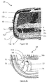
La vue en coupe schématique de la
Hormis cet élément 8i - 21, les autres éléments constituants le projecteur 20 sont identiques à celles du projecteur 10 et portent donc les mêmes références. Plus précisément, le conduit 21 possède une extrémité d'entrée 21e, reliée au bloc 6 de ventilation par couplage sur un embout selon le premier exemple de réalisation (ou alternativement, par soudage thermique, viroles vissées, plots magnétiques, etc.), et deux extrémités de sortie d'air 21 s et 22s.Apart from this
La sortie 22s permet de transmettre de l'air (flèche A4) sous la partie inférieure de déflecteur 8i, en direction de la face interne 8f de la partie arrière concave de déflecteur 8a. L'autre extrémité de sortie 21 s du conduit 21 est située plus près du niveau inférieur de la glace 4 (flèche A5) pour permettre un guidage prolongé de l'air au plus près de la glace 4, de manière semblable au guidage de la
La
De plus, dans cet exemple, un ventilateur de climatiseur 32 du véhicule automobile est relié à l'une des entrées du bloc de ventilation 6 par un tuyau souple 33 et fournit une ventilation forcée (flèche A'1) dans l'entrée 31 e du conduit 31. Le conduit 31 permet de guider de l'air à partir de son extrémité de sortie 31s selon la flèche A6, de manière équivalente au guidage d'air opéré aux extrémités 11 s et 21 s des exemples précédents (cf.
La ventilation forcée peut provenir également d'une centrale de purification et de circulation d'air agencée dans l'habitacle du véhicule. De manière générale, la ventilation peut être fournie par un ventilateur, une turbine, un pulseur entrainé par un moteur électrique ou tout moyen de circulation forcée d'air.The forced ventilation can also come from a central purification and air circulation arranged in the passenger compartment of the vehicle. In general, the ventilation can be provided by a fan, a turbine, a blower driven by an electric motor or any means of forced circulation of air.
Avantageusement, une telle ventilation forcée permet une ventilation même à l'arrêt du véhicule et avec une intensité de ventilation aussi importante que celle permise par la circulation forcée dans l'habitacle. Alternativement, le projecteur peut intégrer un moyen de circulation forcée d'air et la ventilation est alors créée dans le projecteur.Advantageously, such forced ventilation allows ventilation even when the vehicle is stopped and with a ventilation intensity as large as that permitted by the forced circulation in the passenger compartment. Alternatively, the projector can incorporate a means of forced circulation of air and ventilation is then created in the projector.
L'invention n'est pas limitée aux exemples de réalisation décrits et représentés. Elle s'applique à tout type de projecteurs, par exemple aux projecteurs comportant plusieurs sources lumineuses, plusieurs réflecteurs, ou encore un réflecteur à plus de deux parties. Le conduit peut être constitué par un matériau souple formé d'un seul élément ou de plusieurs éléments solidarisés ensemble. Il peut être de section constante ou variable, en particulier décroissante sur une partie de sa longueur.The invention is not limited to the embodiments described and shown. It is applicable to all types of projectors, for example projectors comprising several light sources, several reflectors, or a reflector with more than two parts. The conduit may be constituted by a flexible material formed of a single element or several elements secured together. It can be of constant or variable section, in particular decreasing over part of its length.
Par ailleurs, l'orifice d'entrée d'air peut être positionné à travers toute paroi du boîtier, en particulier à travers la paroi inférieure ou la paroi arrière placée du côté intérieur « I » du véhicule, ou encore dans toute zone qui présente une dépression lorsque le véhicule se déplace (par exemple au niveau inférieur du boîtier dans les exemples illustrés). Dans ce dernier cas, l'air provenant de l'extérieur « E » est aspiré directement.Furthermore, the air inlet orifice can be positioned through any wall of the housing, in particular through the bottom wall or the rear wall. placed on the inner side "I" of the vehicle, or in any area that has a depression when the vehicle moves (for example at the lower level of the housing in the examples shown). In the latter case, the air coming from outside "E" is sucked directly.
Parallèlement, l'orifice de sortie d'air est agencé dans toute paroi du boîtier, de préférence dans une zone du boîtier qui présente une surpression lors du roulage du véhicule, par exemple à travers la paroi supérieure du boîtier. Le nombre de sorties d'air peut être supérieur à deux afin de désembuer plusieurs pièces internes au projecteur autres que la glace.In parallel, the air outlet orifice is arranged in any wall of the housing, preferably in an area of the housing which has an overpressure during the rolling of the vehicle, for example through the upper wall of the housing. The number of air outlets may be greater than two in order to demist several parts internal to the projector other than the ice.
Dans le cas d'une ventilation forcée du projecteur, cette ventilation peut être commandée et réglée par le conducteur à partir de son tableau de bord.In the case of forced ventilation of the headlamp, this ventilation can be controlled and adjusted by the driver from his dashboard.
Le matériau constitutif des conduits est un matériau souple, en particulier un matériau plastique tel qu'un TPE (élastomère thermoplastique), ou à base de polypropylène, de polyéthylène ou de polychlorure de vinyle (PVC). D'autres matériaux à base métallique formant des tresses ou en enroulage hélicoïdal peuvent être utilisés.The constituent material of the conduits is a flexible material, in particular a plastic material such as a TPE (thermoplastic elastomer), or based on polypropylene, polyethylene or polyvinyl chloride (PVC). Other metal-based materials forming braids or helical winding may be used.
De plus, l'invention s'applique à tout type de véhicule comportant au moins un projecteur que l'on souhaite ventiler.In addition, the invention applies to any type of vehicle comprising at least one projector that it is desired to ventilate.
Claims (16)
Applications Claiming Priority (1)
| Application Number | Priority Date | Filing Date | Title |
|---|---|---|---|
| FR1558807A FR3041417B1 (en) | 2015-09-18 | 2015-09-18 | VEHICLE PROJECTOR WITH AERATION SYSTEM |
Publications (2)
| Publication Number | Publication Date |
|---|---|
| EP3144583A1 true EP3144583A1 (en) | 2017-03-22 |
| EP3144583B1 EP3144583B1 (en) | 2018-11-07 |
Family
ID=54848716
Family Applications (1)
| Application Number | Title | Priority Date | Filing Date |
|---|---|---|---|
| EP16188854.0A Active EP3144583B1 (en) | 2015-09-18 | 2016-09-14 | Vehicle headlight with aeration system |
Country Status (3)
| Country | Link |
|---|---|
| EP (1) | EP3144583B1 (en) |
| CN (1) | CN106541882B (en) |
| FR (1) | FR3041417B1 (en) |
Families Citing this family (2)
| Publication number | Priority date | Publication date | Assignee | Title |
|---|---|---|---|---|
| FR3071034B1 (en) * | 2017-09-08 | 2019-08-23 | Psa Automobiles Sa | OPTICAL BLOCK HAS PERIPHERAL HOLES FOR EXHAUSTING ELEMENTS REMOVAL. |
| EP3581848B1 (en) * | 2018-06-13 | 2022-05-11 | Valeo Iluminacion | Automotive lighting device |
Citations (4)
| Publication number | Priority date | Publication date | Assignee | Title |
|---|---|---|---|---|
| DE10026487A1 (en) | 2000-05-27 | 2001-11-29 | Bosch Gmbh Robert | Headlamp for motor vehicle has internal cover element for gap between reflector and housing with at least one opening near both air inlet and air outlet of venting device |
| DE10135849A1 (en) * | 2001-07-23 | 2003-02-06 | Bayerische Motoren Werke Ag | Motor vehicle headlamp has air flow fed to one edge of covering glass panel by air feed arrangement and air feed opening that exits via air outlet opening at edge opposite air feed opening |
| DE10139818A1 (en) * | 2001-08-14 | 2003-02-27 | Opel Adam Ag | Headlamp for a motor vehicle has a casing with a glass covering, a source of light with an associated reflector and a ventilation structure with air inlets and outlets. |
| DE202012009488U1 (en) | 2012-10-04 | 2012-11-09 | Automotive Lighting Reutlingen Gmbh | Lighting device for motor vehicle |
Family Cites Families (7)
| Publication number | Priority date | Publication date | Assignee | Title |
|---|---|---|---|---|
| JPH05225803A (en) * | 1992-02-14 | 1993-09-03 | Stanley Electric Co Ltd | Defogging method for lighting fixture for vehicle |
| DE19934353A1 (en) * | 1999-07-22 | 2001-04-26 | Bosch Gmbh Robert | Headlamp for motor vehicle with housing carrying cover panel with at least one reflector arranged inside housing and with ventilation arrangement having air outlet and inlet and producing ventilation by vacuum lying at air outlet |
| US8398283B2 (en) * | 2009-01-21 | 2013-03-19 | Magna International, Inc. | Automotive signal light employing multi-focal length light pipes |
| FR2950675B1 (en) * | 2009-09-29 | 2013-05-17 | Valeo Vision | LIGHTING AND / OR SIGNALING DEVICE FOR A MOTOR VEHICLE COMPRISING AN AERATION PIPE |
| JP2012226997A (en) * | 2011-04-20 | 2012-11-15 | Koito Mfg Co Ltd | Vehicular headlight |
| CN104344316B (en) * | 2014-10-15 | 2016-09-07 | 台州市轩伟塑业有限公司 | A kind of front directional |
| CN104501059B (en) * | 2014-12-22 | 2017-01-11 | 江苏洪昌科技股份有限公司 | Automotive multifunctional headlamp |
-
2015
- 2015-09-18 FR FR1558807A patent/FR3041417B1/en not_active Expired - Fee Related
-
2016
- 2016-09-14 EP EP16188854.0A patent/EP3144583B1/en active Active
- 2016-09-18 CN CN201610922543.8A patent/CN106541882B/en active Active
Patent Citations (4)
| Publication number | Priority date | Publication date | Assignee | Title |
|---|---|---|---|---|
| DE10026487A1 (en) | 2000-05-27 | 2001-11-29 | Bosch Gmbh Robert | Headlamp for motor vehicle has internal cover element for gap between reflector and housing with at least one opening near both air inlet and air outlet of venting device |
| DE10135849A1 (en) * | 2001-07-23 | 2003-02-06 | Bayerische Motoren Werke Ag | Motor vehicle headlamp has air flow fed to one edge of covering glass panel by air feed arrangement and air feed opening that exits via air outlet opening at edge opposite air feed opening |
| DE10139818A1 (en) * | 2001-08-14 | 2003-02-27 | Opel Adam Ag | Headlamp for a motor vehicle has a casing with a glass covering, a source of light with an associated reflector and a ventilation structure with air inlets and outlets. |
| DE202012009488U1 (en) | 2012-10-04 | 2012-11-09 | Automotive Lighting Reutlingen Gmbh | Lighting device for motor vehicle |
Also Published As
| Publication number | Publication date |
|---|---|
| CN106541882A (en) | 2017-03-29 |
| CN106541882B (en) | 2021-07-13 |
| FR3041417B1 (en) | 2018-08-17 |
| EP3144583B1 (en) | 2018-11-07 |
| FR3041417A1 (en) | 2017-03-24 |
Similar Documents
| Publication | Publication Date | Title |
|---|---|---|
| EP3077678B1 (en) | Suction pulser intended for a heating, ventilation and/or air-conditioning device of a motor vehicle | |
| EP2872783B1 (en) | Ventilation device equipped with a casing shaped as a volute housing | |
| EP3252369B1 (en) | Lighting and/or signalling device for motor vehicle provided with a light module cooled by means of an air flow generator | |
| EP3144583B1 (en) | Vehicle headlight with aeration system | |
| EP1919724B1 (en) | Aeraulic crossmember for a motor vehicle | |
| EP3153770A1 (en) | Cooling air duct for motor vehicle headlight | |
| FR2698055A1 (en) | Ventilated optical unit for motor vehicle headlamp - uses air inlet in front cover of lamp unit and has ducts to carry air to lamp and into engine compartment | |
| WO2021115830A1 (en) | System for cleaning a sensor/transmitter of a motor vehicle | |
| FR2971743A1 (en) | Cooling assembly for front part of motor vehicle i.e. car, has flap connected to support for controlling air suction opening formed in bumper skin, where flexible pipe of support is connected to air suction opening | |
| FR3065379A1 (en) | TELESCOPIC CLEANING DEVICE | |
| FR2804638A1 (en) | Motor vehicle air anti-recycling partition has flexible edge tongues that can be set in different planes relative to main section | |
| FR3010492A1 (en) | LIGHTING DEVICE | |
| EP2960573A2 (en) | Headlight for vehicle with ventilation duct | |
| EP2309178B1 (en) | Lighting and/or signalling device for an automobile | |
| FR3045504A1 (en) | AIR EXHAUST SYSTEM FOR VEHICLES | |
| EP1132269B1 (en) | Cleaning device for rear lights of vehicle | |
| EP1514717B1 (en) | Front end spoiler for motor vehicle, spoiler holding means and front part for motor vehicle | |
| EP2736749B1 (en) | Anti-recycling partition of a motor vehicle. | |
| FR3062368A1 (en) | VEHICLE COMPRISING A WHEEL PASSING AIR DUCT | |
| FR3065380A1 (en) | TELESCOPIC CLEANING DEVICE | |
| EP3558727B1 (en) | System for thermical treatment of a vehicle interior comprising a nebulizer | |
| FR2954419A1 (en) | FAN PROPELLER AND ASSOCIATED FAN NOZZLE, ESPECIALLY FOR MOTOR VEHICLE | |
| FR3133661A1 (en) | Motorized ventilation unit | |
| WO2018202972A1 (en) | Porous air intake duct for hvac | |
| FR2904096A1 (en) | Lighting and signaling device connecting unit for car, has screw with threaded zone provided with grooves oriented longitudinally at axis of screw, where screw has support collar arranged between two threaded zones |
Legal Events
| Date | Code | Title | Description |
|---|---|---|---|
| PUAI | Public reference made under article 153(3) epc to a published international application that has entered the european phase |
Free format text: ORIGINAL CODE: 0009012 |
|
| STAA | Information on the status of an ep patent application or granted ep patent |
Free format text: STATUS: THE APPLICATION HAS BEEN PUBLISHED |
|
| AK | Designated contracting states |
Kind code of ref document: A1 Designated state(s): AL AT BE BG CH CY CZ DE DK EE ES FI FR GB GR HR HU IE IS IT LI LT LU LV MC MK MT NL NO PL PT RO RS SE SI SK SM TR |
|
| AX | Request for extension of the european patent |
Extension state: BA ME |
|
| RAP1 | Party data changed (applicant data changed or rights of an application transferred) |
Owner name: PSA AUTOMOBILES SA Owner name: VALEO VISION |
|
| STAA | Information on the status of an ep patent application or granted ep patent |
Free format text: STATUS: REQUEST FOR EXAMINATION WAS MADE |
|
| 17P | Request for examination filed |
Effective date: 20170823 |
|
| RBV | Designated contracting states (corrected) |
Designated state(s): AL AT BE BG CH CY CZ DE DK EE ES FI FR GB GR HR HU IE IS IT LI LT LU LV MC MK MT NL NO PL PT RO RS SE SI SK SM TR |
|
| REG | Reference to a national code |
Ref country code: DE Ref legal event code: R079 Ref document number: 602016006950 Country of ref document: DE Free format text: PREVIOUS MAIN CLASS: F21S0008100000 Ipc: F21V0031030000 |
|
| GRAP | Despatch of communication of intention to grant a patent |
Free format text: ORIGINAL CODE: EPIDOSNIGR1 |
|
| STAA | Information on the status of an ep patent application or granted ep patent |
Free format text: STATUS: GRANT OF PATENT IS INTENDED |
|
| RIC1 | Information provided on ipc code assigned before grant |
Ipc: F21V 31/03 20060101AFI20180412BHEP Ipc: F21S 45/00 20180101ALI20180412BHEP |
|
| INTG | Intention to grant announced |
Effective date: 20180515 |
|
| RIN1 | Information on inventor provided before grant (corrected) |
Inventor name: SANCHEZ MEDINA, JOSE MANUEL Inventor name: OCHOA IBANEZ, ANA MARIA Inventor name: MOLTO, VALERIE Inventor name: GOMEZ RAMIREZ, MANUEL Inventor name: FERNANDEZ CARCELEN, FRANCISCO Inventor name: ROMERO, NURIA |
|
| GRAS | Grant fee paid |
Free format text: ORIGINAL CODE: EPIDOSNIGR3 |
|
| GRAA | (expected) grant |
Free format text: ORIGINAL CODE: 0009210 |
|
| STAA | Information on the status of an ep patent application or granted ep patent |
Free format text: STATUS: THE PATENT HAS BEEN GRANTED |
|
| AK | Designated contracting states |
Kind code of ref document: B1 Designated state(s): AL AT BE BG CH CY CZ DE DK EE ES FI FR GB GR HR HU IE IS IT LI LT LU LV MC MK MT NL NO PL PT RO RS SE SI SK SM TR |
|
| REG | Reference to a national code |
Ref country code: GB Ref legal event code: FG4D Free format text: NOT ENGLISH |
|
| REG | Reference to a national code |
Ref country code: CH Ref legal event code: EP Ref country code: AT Ref legal event code: REF Ref document number: 1062467 Country of ref document: AT Kind code of ref document: T Effective date: 20181115 |
|
| REG | Reference to a national code |
Ref country code: DE Ref legal event code: R096 Ref document number: 602016006950 Country of ref document: DE |
|
| REG | Reference to a national code |
Ref country code: IE Ref legal event code: FG4D Free format text: LANGUAGE OF EP DOCUMENT: FRENCH |
|
| REG | Reference to a national code |
Ref country code: NL Ref legal event code: MP Effective date: 20181107 |
|
| REG | Reference to a national code |
Ref country code: LT Ref legal event code: MG4D |
|
| REG | Reference to a national code |
Ref country code: AT Ref legal event code: MK05 Ref document number: 1062467 Country of ref document: AT Kind code of ref document: T Effective date: 20181107 |
|
| PG25 | Lapsed in a contracting state [announced via postgrant information from national office to epo] |
Ref country code: IS Free format text: LAPSE BECAUSE OF FAILURE TO SUBMIT A TRANSLATION OF THE DESCRIPTION OR TO PAY THE FEE WITHIN THE PRESCRIBED TIME-LIMIT Effective date: 20190307 Ref country code: NO Free format text: LAPSE BECAUSE OF FAILURE TO SUBMIT A TRANSLATION OF THE DESCRIPTION OR TO PAY THE FEE WITHIN THE PRESCRIBED TIME-LIMIT Effective date: 20190207 Ref country code: AT Free format text: LAPSE BECAUSE OF FAILURE TO SUBMIT A TRANSLATION OF THE DESCRIPTION OR TO PAY THE FEE WITHIN THE PRESCRIBED TIME-LIMIT Effective date: 20181107 Ref country code: HR Free format text: LAPSE BECAUSE OF FAILURE TO SUBMIT A TRANSLATION OF THE DESCRIPTION OR TO PAY THE FEE WITHIN THE PRESCRIBED TIME-LIMIT Effective date: 20181107 Ref country code: LT Free format text: LAPSE BECAUSE OF FAILURE TO SUBMIT A TRANSLATION OF THE DESCRIPTION OR TO PAY THE FEE WITHIN THE PRESCRIBED TIME-LIMIT Effective date: 20181107 Ref country code: ES Free format text: LAPSE BECAUSE OF FAILURE TO SUBMIT A TRANSLATION OF THE DESCRIPTION OR TO PAY THE FEE WITHIN THE PRESCRIBED TIME-LIMIT Effective date: 20181107 Ref country code: BG Free format text: LAPSE BECAUSE OF FAILURE TO SUBMIT A TRANSLATION OF THE DESCRIPTION OR TO PAY THE FEE WITHIN THE PRESCRIBED TIME-LIMIT Effective date: 20190207 Ref country code: FI Free format text: LAPSE BECAUSE OF FAILURE TO SUBMIT A TRANSLATION OF THE DESCRIPTION OR TO PAY THE FEE WITHIN THE PRESCRIBED TIME-LIMIT Effective date: 20181107 Ref country code: LV Free format text: LAPSE BECAUSE OF FAILURE TO SUBMIT A TRANSLATION OF THE DESCRIPTION OR TO PAY THE FEE WITHIN THE PRESCRIBED TIME-LIMIT Effective date: 20181107 |
|
| PG25 | Lapsed in a contracting state [announced via postgrant information from national office to epo] |
Ref country code: AL Free format text: LAPSE BECAUSE OF FAILURE TO SUBMIT A TRANSLATION OF THE DESCRIPTION OR TO PAY THE FEE WITHIN THE PRESCRIBED TIME-LIMIT Effective date: 20181107 Ref country code: PT Free format text: LAPSE BECAUSE OF FAILURE TO SUBMIT A TRANSLATION OF THE DESCRIPTION OR TO PAY THE FEE WITHIN THE PRESCRIBED TIME-LIMIT Effective date: 20190307 Ref country code: SE Free format text: LAPSE BECAUSE OF FAILURE TO SUBMIT A TRANSLATION OF THE DESCRIPTION OR TO PAY THE FEE WITHIN THE PRESCRIBED TIME-LIMIT Effective date: 20181107 Ref country code: RS Free format text: LAPSE BECAUSE OF FAILURE TO SUBMIT A TRANSLATION OF THE DESCRIPTION OR TO PAY THE FEE WITHIN THE PRESCRIBED TIME-LIMIT Effective date: 20181107 Ref country code: NL Free format text: LAPSE BECAUSE OF FAILURE TO SUBMIT A TRANSLATION OF THE DESCRIPTION OR TO PAY THE FEE WITHIN THE PRESCRIBED TIME-LIMIT Effective date: 20181107 Ref country code: GR Free format text: LAPSE BECAUSE OF FAILURE TO SUBMIT A TRANSLATION OF THE DESCRIPTION OR TO PAY THE FEE WITHIN THE PRESCRIBED TIME-LIMIT Effective date: 20190208 |
|
| PG25 | Lapsed in a contracting state [announced via postgrant information from national office to epo] |
Ref country code: CZ Free format text: LAPSE BECAUSE OF FAILURE TO SUBMIT A TRANSLATION OF THE DESCRIPTION OR TO PAY THE FEE WITHIN THE PRESCRIBED TIME-LIMIT Effective date: 20181107 Ref country code: IT Free format text: LAPSE BECAUSE OF FAILURE TO SUBMIT A TRANSLATION OF THE DESCRIPTION OR TO PAY THE FEE WITHIN THE PRESCRIBED TIME-LIMIT Effective date: 20181107 Ref country code: PL Free format text: LAPSE BECAUSE OF FAILURE TO SUBMIT A TRANSLATION OF THE DESCRIPTION OR TO PAY THE FEE WITHIN THE PRESCRIBED TIME-LIMIT Effective date: 20181107 Ref country code: DK Free format text: LAPSE BECAUSE OF FAILURE TO SUBMIT A TRANSLATION OF THE DESCRIPTION OR TO PAY THE FEE WITHIN THE PRESCRIBED TIME-LIMIT Effective date: 20181107 |
|
| REG | Reference to a national code |
Ref country code: DE Ref legal event code: R097 Ref document number: 602016006950 Country of ref document: DE |
|
| PG25 | Lapsed in a contracting state [announced via postgrant information from national office to epo] |
Ref country code: EE Free format text: LAPSE BECAUSE OF FAILURE TO SUBMIT A TRANSLATION OF THE DESCRIPTION OR TO PAY THE FEE WITHIN THE PRESCRIBED TIME-LIMIT Effective date: 20181107 Ref country code: SM Free format text: LAPSE BECAUSE OF FAILURE TO SUBMIT A TRANSLATION OF THE DESCRIPTION OR TO PAY THE FEE WITHIN THE PRESCRIBED TIME-LIMIT Effective date: 20181107 Ref country code: RO Free format text: LAPSE BECAUSE OF FAILURE TO SUBMIT A TRANSLATION OF THE DESCRIPTION OR TO PAY THE FEE WITHIN THE PRESCRIBED TIME-LIMIT Effective date: 20181107 Ref country code: SK Free format text: LAPSE BECAUSE OF FAILURE TO SUBMIT A TRANSLATION OF THE DESCRIPTION OR TO PAY THE FEE WITHIN THE PRESCRIBED TIME-LIMIT Effective date: 20181107 |
|
| PLBE | No opposition filed within time limit |
Free format text: ORIGINAL CODE: 0009261 |
|
| STAA | Information on the status of an ep patent application or granted ep patent |
Free format text: STATUS: NO OPPOSITION FILED WITHIN TIME LIMIT |
|
| 26N | No opposition filed |
Effective date: 20190808 |
|
| PG25 | Lapsed in a contracting state [announced via postgrant information from national office to epo] |
Ref country code: SI Free format text: LAPSE BECAUSE OF FAILURE TO SUBMIT A TRANSLATION OF THE DESCRIPTION OR TO PAY THE FEE WITHIN THE PRESCRIBED TIME-LIMIT Effective date: 20181107 |
|
| PG25 | Lapsed in a contracting state [announced via postgrant information from national office to epo] |
Ref country code: TR Free format text: LAPSE BECAUSE OF FAILURE TO SUBMIT A TRANSLATION OF THE DESCRIPTION OR TO PAY THE FEE WITHIN THE PRESCRIBED TIME-LIMIT Effective date: 20181107 |
|
| PG25 | Lapsed in a contracting state [announced via postgrant information from national office to epo] |
Ref country code: MC Free format text: LAPSE BECAUSE OF FAILURE TO SUBMIT A TRANSLATION OF THE DESCRIPTION OR TO PAY THE FEE WITHIN THE PRESCRIBED TIME-LIMIT Effective date: 20181107 |
|
| REG | Reference to a national code |
Ref country code: CH Ref legal event code: PL |
|
| PG25 | Lapsed in a contracting state [announced via postgrant information from national office to epo] |
Ref country code: IE Free format text: LAPSE BECAUSE OF NON-PAYMENT OF DUE FEES Effective date: 20190914 Ref country code: LU Free format text: LAPSE BECAUSE OF NON-PAYMENT OF DUE FEES Effective date: 20190914 Ref country code: LI Free format text: LAPSE BECAUSE OF NON-PAYMENT OF DUE FEES Effective date: 20190930 Ref country code: CH Free format text: LAPSE BECAUSE OF NON-PAYMENT OF DUE FEES Effective date: 20190930 |
|
| REG | Reference to a national code |
Ref country code: BE Ref legal event code: MM Effective date: 20190930 |
|
| PG25 | Lapsed in a contracting state [announced via postgrant information from national office to epo] |
Ref country code: BE Free format text: LAPSE BECAUSE OF NON-PAYMENT OF DUE FEES Effective date: 20190930 |
|
| PG25 | Lapsed in a contracting state [announced via postgrant information from national office to epo] |
Ref country code: CY Free format text: LAPSE BECAUSE OF FAILURE TO SUBMIT A TRANSLATION OF THE DESCRIPTION OR TO PAY THE FEE WITHIN THE PRESCRIBED TIME-LIMIT Effective date: 20181107 |
|
| PG25 | Lapsed in a contracting state [announced via postgrant information from national office to epo] |
Ref country code: HU Free format text: LAPSE BECAUSE OF FAILURE TO SUBMIT A TRANSLATION OF THE DESCRIPTION OR TO PAY THE FEE WITHIN THE PRESCRIBED TIME-LIMIT; INVALID AB INITIO Effective date: 20160914 Ref country code: MT Free format text: LAPSE BECAUSE OF FAILURE TO SUBMIT A TRANSLATION OF THE DESCRIPTION OR TO PAY THE FEE WITHIN THE PRESCRIBED TIME-LIMIT Effective date: 20181107 |
|
| PG25 | Lapsed in a contracting state [announced via postgrant information from national office to epo] |
Ref country code: MK Free format text: LAPSE BECAUSE OF FAILURE TO SUBMIT A TRANSLATION OF THE DESCRIPTION OR TO PAY THE FEE WITHIN THE PRESCRIBED TIME-LIMIT Effective date: 20181107 |
|
| PGFP | Annual fee paid to national office [announced via postgrant information from national office to epo] |
Ref country code: GB Payment date: 20230823 Year of fee payment: 8 |
|
| PGFP | Annual fee paid to national office [announced via postgrant information from national office to epo] |
Ref country code: FR Payment date: 20230822 Year of fee payment: 8 Ref country code: DE Payment date: 20230822 Year of fee payment: 8 |