EP3144397B1 - Système de prises d'extinction et utilisations correspondantes - Google Patents
Système de prises d'extinction et utilisations correspondantes Download PDFInfo
- Publication number
- EP3144397B1 EP3144397B1 EP16189415.9A EP16189415A EP3144397B1 EP 3144397 B1 EP3144397 B1 EP 3144397B1 EP 16189415 A EP16189415 A EP 16189415A EP 3144397 B1 EP3144397 B1 EP 3144397B1
- Authority
- EP
- European Patent Office
- Prior art keywords
- mandrel
- workpiece
- plug
- tapered plug
- quench
- Prior art date
- Legal status (The legal status is an assumption and is not a legal conclusion. Google has not performed a legal analysis and makes no representation as to the accuracy of the status listed.)
- Active
Links
Images





Classifications
-
- C—CHEMISTRY; METALLURGY
- C21—METALLURGY OF IRON
- C21D—MODIFYING THE PHYSICAL STRUCTURE OF FERROUS METALS; GENERAL DEVICES FOR HEAT TREATMENT OF FERROUS OR NON-FERROUS METALS OR ALLOYS; MAKING METAL MALLEABLE, e.g. BY DECARBURISATION OR TEMPERING
- C21D1/00—General methods or devices for heat treatment, e.g. annealing, hardening, quenching or tempering
- C21D1/62—Quenching devices
-
- C—CHEMISTRY; METALLURGY
- C21—METALLURGY OF IRON
- C21D—MODIFYING THE PHYSICAL STRUCTURE OF FERROUS METALS; GENERAL DEVICES FOR HEAT TREATMENT OF FERROUS OR NON-FERROUS METALS OR ALLOYS; MAKING METAL MALLEABLE, e.g. BY DECARBURISATION OR TEMPERING
- C21D1/00—General methods or devices for heat treatment, e.g. annealing, hardening, quenching or tempering
- C21D1/18—Hardening; Quenching with or without subsequent tempering
-
- C—CHEMISTRY; METALLURGY
- C21—METALLURGY OF IRON
- C21D—MODIFYING THE PHYSICAL STRUCTURE OF FERROUS METALS; GENERAL DEVICES FOR HEAT TREATMENT OF FERROUS OR NON-FERROUS METALS OR ALLOYS; MAKING METAL MALLEABLE, e.g. BY DECARBURISATION OR TEMPERING
- C21D6/00—Heat treatment of ferrous alloys
-
- C—CHEMISTRY; METALLURGY
- C21—METALLURGY OF IRON
- C21D—MODIFYING THE PHYSICAL STRUCTURE OF FERROUS METALS; GENERAL DEVICES FOR HEAT TREATMENT OF FERROUS OR NON-FERROUS METALS OR ALLOYS; MAKING METAL MALLEABLE, e.g. BY DECARBURISATION OR TEMPERING
- C21D9/00—Heat treatment, e.g. annealing, hardening, quenching or tempering, adapted for particular articles; Furnaces therefor
- C21D9/0068—Heat treatment, e.g. annealing, hardening, quenching or tempering, adapted for particular articles; Furnaces therefor for particular articles not mentioned below
Definitions
- This disclosure relates to systems and apparatus for metalworking. More particularly, this disclosure relates to heat treating and quenching a metal workpiece.
- Metalworking includes a variety of methods of working with metals or metal alloys to create individual parts, assemblies, or large-scale structures.
- One aspect of many metalworking techniques is quenching, or quickly reducing a temperature of the metal.
- the slower the quench rate e.g., a relatively longer time to reduce the temperature of the metal
- the longer thermodynamic forces have a chance to alter the microstructure of the metal, which may be desirable.
- a faster quench rate is used to prevent the microstructure of the metal from altering significantly as it passes through a range of lower temperatures during cooling. Heating and quenching is most commonly carried out in order to harden a given manufactured component.
- the stresses of rapid quenching can sometimes result in distortion and warping of the workpiece.
- Such distortions may not meet a high degree of precision in the workpiece's dimensions and/or geometry.
- One way of preventing or reducing such distortion is the insertion of a quench plug into an internal cavity of the workpiece while the workpiece is at high temperature, followed by quenching the assembled workpiece/quench plug.
- the quench plug may be configured to preserve the shape of the component while the component is being quenched.
- the presence of the quench plug may also result in a degree of plastic deformation of the component as the component cools and shrinks, thereby relieving stresses in the metal structure of the workpiece.
- This process typically uses a quench plug that is at room temperature be inserted into a workpiece while the workpiece is hot, perhaps as hot as 1,600° F (870° C).
- the rigors of manually working with such hot materials may result in inconsistencies in the placement of the plug tool, or the timing of the quench delay.
- the contraction of the workpiece around a misaligned quench plug may result in the plug being tightly held by the workpiece, and significant force may be applied to remove the quench plug, increasing the risk of altering the workpiece and adding to the cost of the heat treatment process.
- JP-U-S604563 there is described a jig for heat treatment of a thin-walled cylindrical member.
- the present disclosure provides quench plug systems and methods for heat treating a workpiece.
- a quench plug system for use in heat treating a workpiece, the quench plug system comprising: a mandrel; and a tapered plug having a longitudinal core axis and configured to be inserted into a central cavity of the mandrel, wherein the tapered plug is configured to allow the mandrel to translate along the core axis of the tapered plug when the mandrel is heated, and wherein the tapered plug has a lower coefficient of thermal expansion than a coefficient of thermal expansion of the mandrel.
- Also described herein is a method for heat treating a workpiece, the method comprising: inserting a mandrel into the workpiece before the workpiece is heated, inserting a tapered plug having a core axis into the mandrel before the mandrel is heated, wherein the tapered plug has a lower coefficient of thermal expansion than a coefficient of thermal expansion of the mandrel, heating the workpiece such that the tapered plug translates along the core axis further into the mandrel during the heating step, and cooling the workpiece to form a final shape of the workpiece.
- the method of heat treating a workpiece includes inserting a plug inside a workpiece, heating the workpiece until the workpiece has expanded to a desired dimension, cooling the workpiece, and removing the plug from the workpiece, where the workpiece expands to and maintains a desired dimension without the insertion of any structure into the workpiece during either the heating or the cooling steps.
- Described herein is a quench plug system that can be placed with respect to a workpiece without an operator interacting with extremely hot materials.
- the herein-described quench plug system accommodates the expansion of the workpiece during heating and at least substantially resists the contraction of the workpiece during quenching. Further, the quench plug system may be readily removed after quenching is complete.
- quench plug systems and methods of heat treating a workpiece are described below and illustrated in the associated drawings.
- the quench plug systems of the present disclosure and/or their various components may, but are not required to, contain at least one of the structures, components, functionality, and/or variations described, illustrated, and/or incorporated herein.
- the structures, components, functionalities, and/or variations described, illustrated, and/or incorporated herein in connection with the present teachings may, but are not required to, be included in other similar quench plug systems.
- the advantages possessed or exhibited by selected aspects, as described below, are illustrative in nature. The following description of various aspects is exemplary in nature and is in no way intended to limit the disclosure, its application, or uses.
- quench plug systems depicted in the associated drawings are selected to illustrate various aspects of the present disclosure, and one or more of the proportions, orientations, and relative spacing of the depicted quench plug components may be exaggerated for the purposes of such illustration. In particular, the amount of expansion of the workpiece and selected components of the depicted quench plug systems may be exaggerated.
- the quench plug systems and methods of heat treating a workpiece described herein may possess particular utility for the heat treatment of selected metal workpieces, particularly but not exclusively where the workpiece may define an internal cavity.
- the disclosed systems and methods may permit the heat treatment of a workpiece that includes inserting the quench plug system into the workpiece when the workpiece is at or near room temperature, with the workpiece being heated to a higher temperature, and subsequently quenched.
- the quench plug systems disclosed herein may additionally be easy to remove after the quenching of the workpiece.
- Fig. 1 is a cross-section view of an exemplary quench plug system 10 that includes a tapered plug 12 configured to be inserted into a central cavity 13 of a mandrel 14.
- the exemplary quench plug system 10 is configured to be inserted at least substantially within a cavity defined by a workpiece 16.
- the tapered plug 12 may be substantially frusto-conical
- the mandrel 14 may have an outer surface 15 that is substantially cylindrical
- the cavity defined by the workpiece 16 may have an inner surface 17 that is substantially cylindrical.
- the tapered plug 12 and the mandrel 14 are constructed so that the mandrel 14 can expand at a faster rate than the tapered plug 12.
- This differential expansion may be effected by any satisfactory method, such as by differentially heating the mandrel 14 and the tapered plug 12 so that the mandrel 14 and the tapered plug 12 exhibit differential thermal expansion rates.
- the materials forming the tapered plug 12 and the mandrel 14 may be selected to exhibit substantially different coefficients of thermal expansion if subjected to the same heating process.
- the tapered plug 12 may include one or more materials having a relatively small coefficient of thermal expansion, such as for example Invar alloy and/or titanium metal.
- the mandrel 14 includes materials having a relatively larger coefficient of thermal expansion, such as for example a steel alloy. Alternatively, or in addition, the mandrel 14 may be constructed so that the mandrel 14 is mechanically capable of expanding in a radial direction.
- the tapered plug 12 may include a substantially nonconductive material
- the mandrel 14 and the workpiece 16 include conductive materials, such that by placing the quench plug system 10 and the workpiece 16 in an inductive heater, the workpiece 16 and the mandrel 14 may be subjected to an increased rate of heating compared to the rate of heating of the tapered plug 12.
- both the tapered plug 12 and the mandrel 14 may include a substantially nonconductive material, while the workpiece 16 includes conductive materials, so that inductive heating heats the workpiece 16 at a rate of heating greater than that experienced by either the mandrel 14 or the tapered plug 12.
- the mandrel 14 may be configured so that the mandrel 14 may be interposed between the tapered plug 12 and the workpiece 16.
- Fig. 1 represents an initial state of the tapered plug 12, the mandrel 14, and the workpiece 16 prior to a heat treatment of the workpiece 16. At this initial state the quench plug system 10 and the workpiece 16 are substantially at room temperature before a heat treatment process is performed on the workpiece 16.
- the workpiece 16 may undergo greater thermal expansion than the thermal expansion exhibited by the tapered plug 12, such that an increased inner circumference of the internal cavity of the workpiece 16, relative to the outer circumference of the tapered plug 12, may thereby allow the workpiece 16 and the mandrel 14 to translate downwardly along the tapered plug 12, as shown in Fig. 2 .
- the mandrel 14 may undergo a corresponding radial expansion.
- the workpiece 16 may contract. However, as the workpiece 16 comes into contact with the expanded mandrel 14, the workpiece 16 may be physically prevented from contracting further, resulting in a degree of plastic deformation of the workpiece 16 as the workpiece 16 continues to cool. The plastic deformation of the workpiece 16 relieves stresses in the metal structure of the workpiece 16 as the workpiece 16 undergoes forming and/or correction as the workpiece 16 is cooled.
- the tapered plug 12, the mandrel 14, and the workpiece 16 may be constructed so that each of the tapered plug 12, the mandrel 15, and the workpiece 16 exhibits rotational symmetry with respect to a central core axis 18 of the tapered plug 12. That is, the tapered plug 12, the mandrel 14, and the workpiece 16 are nested in a substantially concentric fashion.
- the tapered plug 12 includes an external taper having an outside taper angle 24.
- the tapered plug 12 may be substantially frusto-conical, or may be a truncated polygonal pyramid, such as a trigonal pyramid, a tetragonal pyramid, or any other suitable shape that enables the quench plug system 10 to function substantially as described herein.
- the tapered plug 12 may have a first end 26 and a second end 28, where the outside taper angle 24 results in the second end 28 having a larger circumference than a circumference of the first end 26.
- the increasing circumference of the tapered plug 12 at the broader second end 28 of the tapered plug 12, relative to the circumference of the first end 26 of the tapered plug 12 may function to prevent any substantial subsequent radial contraction of the workpiece 16 as the workpiece 16 cools.
- Tapered plug 12 may optionally include an internal cavity 20, which may be accessed via a plug opening 22.
- the plug opening 22 may be centered on the core axis 18 of the tapered plug 12.
- the mandrel 14 may be configured to undergo an expansion as the mandrel 14 translates along the tapered plug 12 parallel to the core axis 18 toward the second end 28 of the tapered plug 12.
- the translation of the mandrel 14 along the core axis 18 may be facilitated when the mandrel 14 has an inside taper angle 30 that is substantially complementary to the outside taper angle 24 of the tapered plug 12, where the inside taper angle 30 and the outside taper angle 24 are measured relative to a plane 31 that is orthogonal to the core axis 18, as depicted in Fig. 1 .
- the inside taper angle 30 and the outside taper angle 24 are complementary when the sum of the inside taper angle 30 and the outside taper angle 24 is substantially equal to 180 degrees.
- the absolute deviation of the inside taper angle 30 from the vertical axis and the absolute deviation of the outside taper angle 24 from the vertical axis are substantially equivalent.
- the mandrel 14 may be reusable. For example, after expansion, the mandrel 14 may be removed from the tapered plug 12 and mechanically reconfigured to return to the mandrel's original circumference, for example by an inward radial compression. Alternatively, the mandrel 14 may be configured to undergo nonreversible expansion. In some aspects, a new mandrel may be used during each heat treatment process.
- the components of the quench plug system 10 may include the frusto-conical tapered plug 12, and the mandrel 14 that is complementary to the tapered plug 12, that is, the inside taper angle 30 of the mandrel 14 is complementary to the outside taper angle 24 of the tapered plug 12.
- the mandrel 14 may include a peripheral lip 40 along a circumference of its lower edge. The peripheral lip 40 may be configured to prevent the workpiece 16 from translating along the core axis 18 beyond the lower edge of the mandrel 14.
- the mandrel 14 may be interposed between the workpiece 16 and the tapered plug 12 prior to heating the workpiece 16.
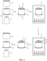
- the combination of the workpiece 16 and the quench plug system 10 may be exposed to a heating device 42, for example a furnace or inductive heater.
- the workpiece 16 and the quench plug system 10 may be heated sufficiently by heat source 42 that the workpiece 16 and the mandrel 14 have translated parallel to and along the core axis 18 of the tapered plug 12 as the workpiece 16 radially expands. This permits the mandrel 14 to radially expand.
- the workpiece 16 and the quench plug system 10 are removed from the heating device 42 and permitted to cool to a relatively lower temperature, such as room temperature.
- a relatively lower temperature such as room temperature.
- the tapered plug 12 may be removed from the mandrel 14 and the mandrel 14 may be removed from the workpiece 16.
- the workpiece 16 has a desired shape.
- Figs. 4 and 5 schematically depict a selected configuration for a mandrel 14 according to the present disclosure.
- the mandrel 14 may be interposed between the tapered plug 12 and the workpiece 16.
- the mandrel 14 may include multiple individual mandrel components 50.
- the mandrel components 50 may be configured so that by arranging the mandrel components 50 circumferentially adjacent to each other the mandrel 14 is formed.
- the mandrel components 50 may include multiple component sizes and/or shapes, provided that when the mandrel components 50 are appropriately arranged circumferentially adjacent to each other, the desired mandrel 14 is formed.
- the mandrel components 50 may correspond to radial sections of the mandrel 14 having substantially similar sizes and shapes. Alternatively, the mandrel components 50 may have distinct shapes and/or sizes, provided they assemble into the mandrel 14. As shown in Figs. 4 and 5 , the mandrel 14 may include individual mandrel components 50 having a side wall 52 that is coincident with a radius of the mandrel 14, or side wall 54 that is set at an angle to a radius of the mandrel 14, again provided that when the mandrel components 50 are appropriately arranged circumferentially adjacent to each other, the desired mandrel 14 is formed.
- the workpiece 16 and the mandrel 14 may translate downwardly along the core axis 18 of the tapered plug 12.
- the individual mandrel components 50 of the mandrel 14 may separate from one another, introducing spaces 56 between the individual mandrel components 50, as shown in Fig. 5 .
- the expansion of the mandrel 14 of Fig. 5 is primarily due to the introduction of the spaces 56 between the individual mandrel components 50.
- the radial expansion of the workpiece 16 and the mandrel 14 depicted in Fig. 5 may be exaggerated for the purposes of illustration.
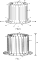
- Figs. 6 and 7 schematically depict a selected configuration for a mandrel according to the present disclosure.
- the mandrel 14 may incorporate a plurality of longitudinal slits 58 that originate alternately at an upper surface 59 and a lower surface 60 of the mandrel 14.
- Each longitudinal slit 58 extends in a direction parallel to the core axis 18 of the tapered plug 12 occupying the central cavity 13 of the mandrel 14.
- Each longitudinal slit 58 extends partly along a height 61 of the mandrel 14, but does not extend to the opposite surface of the mandrel 14 from the originating surface of the slit.
- the mandrel 14 may expand radially outwardly mechanically as the longitudinal slits 54 widen, as shown in Fig. 7 .
- the mandrel 14 may be configured to facilitate the use of a quench fluid to aid in quenching the workpiece.
- the outer surface of the mandrel component may incorporate one or more recessed channels that may be configured to permit a quench fluid to circulate between the outer surface of the mandrel and the inner surface of a surrounding workpiece. In this way, contact between the quench fluid and the workpiece may be increased, and so the resulting rate of cooling of the workpiece may be increased.
- the recessed channels in the outer surface of the mandrel may be configured to circulate any appropriate quench fluid, including for example water, water mixed with one or more additives, organic or inorganic oils, or inert gases, among others.
- the quench plug systems of the present disclosure may incorporate mandrels having an additional or alternative configuration, without limitation, provided that the mandrel may be appropriately interposed between the tapered plug of the quench plug system and the workpiece of interest, and further provided that the mandrel is additionally configured to translate along the core axis of the tapered plug when the workpiece and optionally the quench plug system is heated.
- This example describes an illustrative quench plug system 10 according to an embodiment of the present disclosure, as shown in cross-section views in Figs. 8-11 .
- Fig. 8 is a cross-section view of an illustrative quench plug system 10 that includes the tapered plug 12, and the mandrel 14.
- the tapered plug 12 additionally includes a plate 62 that is oriented orthogonally to the core axis 18 of tapered plug 12.
- the plate 62 may be secured to tapered plug 12.
- the tapered plug 12 may additionally be secured to a base 64 by coupling the plate 62 of the tapered plug 12 beneath the base 64 so that the tapered plug 12 extends along the core axis 18 from the base 64.
- the horizontal plate 62 may secured to the base 64 by the fasteners 66.
- the fasteners 66 may be screws, bolts, or any other appropriate fastening device that secure the plate 62 to the base 64.
- the mandrel 14 may include a peripheral lip 40 along an edge of the mandrel 14 adjacent to the base 64 in order to prevent the workpiece 16 from translating beyond the peripheral lip 40.
- the workpiece 16 and the mandrel 14 translate along the core axis 18 of the tapered plug 12 under the effect of gravity.
- the mandrel 14 may translate along the core axis 18 only until the mandrel 14 makes contact with the base 64, as shown in Fig. 9 .
- the exemplary configuration of the quench plug system 10 may be useful where it is desirable to limit a degree of expansion of the workpiece 16.
- the fasteners 66 may be removed from the base 64 and the plate 62, as shown in Fig. 10 .
- the tapered plug 12 may then be removed from the mandrel 14 by translating the tapered plug 12 along the core axis 18, as shown in Fig. 11 .
- This example describes the illustrative quench plug system 10 according to an embodiment of the present disclosure, as shown in cross-section views in Figs. 12 and 13 .
- Fig. 12 is a cross-section view of the illustrative quench plug system 10 that may include the tapered plug 12, and the mandrel 14.
- the tapered plug 12 may additionally include the plate 62 oriented orthogonally to the core axis 18 of the tapered plug 12.
- the mandrel 14 may be interposed between the tapered plug 12 and the workpiece 16.
- Fig. 12 depicts the quench plug system 10 before the workpiece 16 is heated.
- the quench plug system 10 is configured so that the mandrel 14 and the workpiece 16 translate independently from each other along the core axis 18 relative to the tapered plug 12 when the workpiece 16 is heated.
- the mandrel 14 may translate downwardly along the core axis 18 of the tapered plug 12 under the effect of gravity.
- the mandrel 14 may be limited in its downward translation by contact between the mandrel 14 and the plate 62.
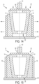
- This example describes the illustrative quench plug system 10 according to an embodiment of the present disclosure, as shown in cross-section views in Figs. 14 and 15 .
- Fig. 14 is a cross-section view of the illustrative quench plug system 10 that includes the tapered plug 12, and the mandrel 14.
- the tapered plug 12 is configured to allow the mandrel 14 to translate along the core axis 18 of the tapered plug 12 when the workpiece 16 is heated.
- the tapered plug 12 includes the first end 26 and the second end 28, where the second end 28 has a larger circumference than the circumference of the first end 26.
- the quench plug system 10 further includes the plate 62 that is oriented orthogonally to the core axis 18 of the tapered plug 12; however, in contrast to the quench plug system 10 of Figs. 12 and 13 , the plate 62 is disposed adjacent to but spaced from the first end 26 of the tapered plug 12.
- the quench plug system 10 may be configured so that upon heating the workpiece 16, the tapered plug 12 may translate toward the plate 62. As the tapered plug 12 translates toward the plate 62, the mandrel 14 may translate along the core axis 18 of the tapered plug 12 toward the second end 28 of the tapered plug 12, expanding as it does so. The tapered plug 12 can translate along the core axis 18 until the first end 26 of the tapered plug 12 meets the plate 62. as shown in Fig. 15 , at which point the quench plug system 10 and the workpiece 16 may be cooled.
- the quench plug system 10 may further include a press 90 configured to apply a force (in addition to gravitational force) to assist in translating tapered plug 12 toward the plate 62.
- the force may be applied to one or more of the tapered plug 12, the mandrel 14, or both components of the particular quench plug system 10, and such forces may be applied parallel to the core axis 18 of the tapered plug 12 of the particular quench plug system 10.
- FIG. 16 An illustrative method of heat treating a workpiece 16 is depicted by flowchart 92 of Fig. 16 .
- the illustrative method includes inserting a mandrel 14 into a workpiece 16 before the workpiece 16 is heated (at 94 of flowchart 92), inserting a tapered plug 12 having a core axis 18 into the mandrel 14 before the mandrel 14 is heated (at 96 of flowchart 92), heating the workpiece 16 such that the tapered plug 12 translates along the core axis 18 further into the mandrel 14 during the heating step (at 98 of flowchart 92), and cooling the workpiece 16 to form a final shape of the workpiece 16 (at 100 of flowchart 92).
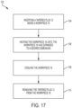
- FIG. 17 An alternative illustrative method of heat treating a workpiece 16 is depicted by flowchart 102 of Fig. 17 .
- the illustrative method includes inserting a tapered plug 12 inside a workpiece 16 (at 104 of flowchart 102), heating the workpiece 16 until the workpiece 16 has expanded to a desired dimension (at 106 of flowchart 102), cooling the workpiece 16 (at 108 of flowchart 102), and removing the tapered plug 12 from the workpiece 16 (at 110 of flowchart 102), where the workpiece 16 expands to and maintains a desired dimension without the insertion of any structure into the workpiece during either the heating or the cooling steps.
- the different embodiments of the quench plug systems and methods of heat treating a workpiece described herein provide several advantages over known approaches to prevent the warping of metal components when they are heat treated and quenched.
- quench plugs in the heat treatment of metal components require a cool quench plug to be inserted into a workpiece that is already at high temperature. To avoid the high temperatures, placement of the quench plug may be rushed, and therefore the quench plug may not be optimally positioned in the workpiece. After quenching, the quench plug may be retained in the workpiece by the contraction of the workpiece and therefore difficult to remove.
- the quench plug systems of the present disclosure permit the quench plug system to be inserted into the workpiece before the quench plug system or the workpiece is heated.
- the combined workpiece and quench plug system may be heated together, and then quenched directly, without manual intervention. Due to its construction the quench plug system does not substantially contract upon cooling, permitting the quench plug system to preserve the desired shape of the workpiece during quenching, and relieve stresses that might otherwise be created in the metal structure of the workpiece.
Landscapes
- Chemical & Material Sciences (AREA)
- Engineering & Computer Science (AREA)
- Physics & Mathematics (AREA)
- Thermal Sciences (AREA)
- Crystallography & Structural Chemistry (AREA)
- Mechanical Engineering (AREA)
- Materials Engineering (AREA)
- Metallurgy (AREA)
- Organic Chemistry (AREA)
- Heat Treatment Of Articles (AREA)
- Heat Treatments In General, Especially Conveying And Cooling (AREA)
Claims (16)
- Système de bouchon d'extinction (10) destiné à être utilisé dans le traitement thermique d'une pièce à usiner (16), le système de bouchon d'extinction comprenant :un mandrin (14) ; etun bouchon conique (12) présentant un axe central longitudinal (18) et configuré pour être inséré dans une cavité centrale du mandrin (14),dans lequel le bouchon conique (12) est configuré pour permettre au mandrin (14) de se déplacer le long de l'axe central du bouchon conique (12) lorsque le mandrin (14) est chauffé, et dans lequel le bouchon conique (12) présente un coefficient de dilatation thermique inférieur à un coefficient de dilatation thermique du mandrin (14).
- Système de bouchon d'extinction (10) selon la revendication 1, dans lequel le bouchon conique (12) inclut au moins un parmi un alliage Invar ou un métal de titane.
- Système de bouchon d'extinction (10) selon la revendication 1 ou 2, dans lequel le bouchon conique (12) présente un angle de cône extérieur (24) et le mandrin (14) présente un angle de cône intérieur (30), et l'angle de cône extérieur du bouchon conique (12) est complémentaire de l'angle de cône intérieur (30) du mandrin (14).
- Système de bouchon d'extinction (10) selon l'une quelconque des revendications 1 à 3, dans lequel le bouchon conique (12) est sensiblement tronconique, et le mandrin (14) présente une surface extérieure (15) qui est sensiblement cylindrique.
- Système de bouchon d'extinction (10) selon l'une quelconque des revendications 1 à 4, dans lequel le mandrin (14) inclut une pluralité de composants de mandrin individuels (50), de sorte que lorsque le mandrin (14) se déplace en translation le long de l'axe central (18) du bouchon conique (12), le diamètre extérieur du mandrin (14) augmente.
- Système de bouchon d'extinction (10) selon l'une quelconque des revendications 1 à 4, dans lequel le mandrin (14) inclut une pluralité de fentes longitudinales (58) provenant alternativement d'une surface supérieure (59) et d'une surface inférieure (60) du mandrin (14), chaque fente longitudinale s'étendant sur une partie d'une hauteur (61) du mandrin (14).
- Système de bouchon d'extinction (10) selon l'une quelconque des revendications 1 à 6, comprenant en outre une base (64) qui est configurée pour être couplée au bouchon conique (12).
- Système de bouchon d'extinction (10) selon l'une quelconque des revendications 1 à 7, dans lequel le bouchon conique (12) inclut un matériau sensiblement non conducteur, le système de bouchon d'extinction comprenant en outre un dispositif de chauffage inductif configuré pour chauffer le mandrin (14) sans chauffer sensiblement le bouchon conique (12).
- Système de bouchon d'extinction (10) selon l'une quelconque des revendications 1 à 8, comprenant en outre une pièce à usiner (16), dans lequel le mandrin (14) est configuré pour être interposé entre le bouchon conique (12) et la pièce à usiner (16), dans lequel le bouchon conique (12) est configuré pour permettre au mandrin (14) de se déplacer en translation le long de l'axe central du bouchon conique (12) lorsque la pièce à usiner (16) est chauffée.
- Procédé de traitement thermique d'une pièce à usiner (16), le procédé comprenant les étapes consistant à :insérer un mandrin (14) dans la pièce à usiner (16) avant que la pièce à usiner (16) ne soit chauffée,insérer un bouchon conique (12) présentant un axe central (18) dans le mandrin (14) avant que le mandrin (14) ne soit chauffé, dans lequel le bouchon conique (12) présente un coefficient de dilatation thermique inférieur à un coefficient de dilatation thermique du mandrin (14),chauffer la pièce à usiner (16) de telle sorte que le bouchon conique (12) se déplace le long de l'axe central plus loin dans le mandrin (14) pendant l'étape de chauffage, etrefroidir la pièce à usiner (16) pour former une forme finale de la pièce à usiner (16).
- Procédé selon la revendication 10, dans lequel le bouchon conique (12) inclut au moins un parmi un alliage Invar ou un métal de titane.
- Procédé selon la revendication 10 ou 11, dans lequel le bouchon conique (12) inclut une première extrémité (26) et une seconde extrémité (28), la seconde extrémité (28) présentant une circonférence plus grande qu'une circonférence de la première extrémité (26) ; et dans lequel le chauffage du mandrin (14) et de la pièce à usiner (16) inclut un déplacement en translation du mandrin (14) le long de l'axe central (18) vers la seconde extrémité (28) du bouchon conique (12).
- Procédé selon l'une quelconque des revendications 10 à 12, comprenant en outre un déplacement en translation de la pièce à usiner (16) et du mandrin (14) le long de l'axe central (18) par rapport au bouchon conique (12) pendant l'étape de chauffage, où la pièce à usiner (16) et le mandrin (14) se déplacent en translation ensemble ou indépendamment par rapport au bouchon conique (12).
- Procédé selon l'une quelconque des revendications 10 à 13, dans lequel le chauffage du mandrin (14) et de la pièce à usiner (16) inclut un déplacement translation du bouchon conique (12) le long de l'axe central (18) du bouchon conique (12) par rapport à la fois au mandrin (14) et à la pièce à usiner (16).
- Procédé selon l'une quelconque des revendications 10 à 14, comprenant en outre un déplacement en translation du mandrin (14) et de la pièce à usiner (16) le long de l'axe central (18) par rapport au bouchon conique (12) au moins partiellement en raison d'une force gravitationnelle.
- Procédé selon l'une quelconque des revendications 10 à 15, comprenant en outre un déplacement en translation du mandrin (14) et de la pièce à usiner (16) par rapport au bouchon conique (12) au moins partiellement en raison d'une force mécanique.
Applications Claiming Priority (1)
| Application Number | Priority Date | Filing Date | Title |
|---|---|---|---|
| US14/856,479 US10214789B2 (en) | 2015-09-16 | 2015-09-16 | Quench plug systems and their use |
Publications (2)
| Publication Number | Publication Date |
|---|---|
| EP3144397A1 EP3144397A1 (fr) | 2017-03-22 |
| EP3144397B1 true EP3144397B1 (fr) | 2024-05-08 |
Family
ID=57113039
Family Applications (1)
| Application Number | Title | Priority Date | Filing Date |
|---|---|---|---|
| EP16189415.9A Active EP3144397B1 (fr) | 2015-09-16 | 2016-09-19 | Système de prises d'extinction et utilisations correspondantes |
Country Status (4)
| Country | Link |
|---|---|
| US (1) | US10214789B2 (fr) |
| EP (1) | EP3144397B1 (fr) |
| JP (1) | JP6846146B2 (fr) |
| CN (1) | CN106544482B (fr) |
Families Citing this family (3)
| Publication number | Priority date | Publication date | Assignee | Title |
|---|---|---|---|---|
| CN109371221B (zh) * | 2018-07-20 | 2020-05-22 | 江麓机电集团有限公司 | 一种复合排渗碳薄壁齿圈压力淬火工装及处理方法 |
| CN108950157B (zh) * | 2018-07-20 | 2020-05-22 | 江麓机电集团有限公司 | 一种渗碳薄壁齿圈组合式压力淬火工装 |
| CN114686671B (zh) * | 2022-04-19 | 2024-07-09 | 中国科学院近代物理研究所 | 用于磁合金环热处理的柔性内衬 |
Citations (1)
| Publication number | Priority date | Publication date | Assignee | Title |
|---|---|---|---|---|
| JPS604563U (ja) * | 1983-06-24 | 1985-01-14 | 日産自動車株式会社 | 熱処理用治具 |
Family Cites Families (14)
| Publication number | Priority date | Publication date | Assignee | Title |
|---|---|---|---|---|
| JPS5336984Y2 (fr) * | 1974-07-30 | 1978-09-08 | ||
| JPS5831369B2 (ja) * | 1975-12-05 | 1983-07-05 | エヌ テ− エヌトウヨウベアリング カブシキガイシヤ | 環状物品の内径矯正装置 |
| JPS6237315A (ja) * | 1985-08-08 | 1987-02-18 | Nippon Seiko Kk | 環状体の焼入れ方法とその装置 |
| US4761191A (en) | 1986-12-23 | 1988-08-02 | Trw Inc. | Method of forming closely sized openings |
| WO1994019499A1 (fr) * | 1993-02-19 | 1994-09-01 | Ab S K F | Procede et dispositif de traitement thermique |
| WO1996006194A1 (fr) * | 1994-08-24 | 1996-02-29 | Nsk Ltd. | Procede et appareil permettant de soumettre une piece a laminer a revenu correctif |
| DE29504242U1 (de) | 1995-03-11 | 1995-05-04 | Karl Heess GmbH & Co Maschinenbau, 68623 Lampertheim | Spreizdorn für Härtevorrichtungen |
| US6120570A (en) | 1996-02-14 | 2000-09-19 | Smith International | Process for manufacturing inserts with holes for clamping |
| JP3280905B2 (ja) * | 1998-02-03 | 2002-05-13 | 中村 滋 | 円筒状ワークの焼入れ用治具 |
| CN2700335Y (zh) * | 2004-04-30 | 2005-05-18 | 洛阳轴承集团有限公司 | 用于轴承套圈热处理的组合活动模具 |
| JP2006137997A (ja) * | 2004-11-12 | 2006-06-01 | Toyota Motor Corp | 中空部材の焼き入れ装置及び焼き入れ方法 |
| JP5465450B2 (ja) * | 2009-03-23 | 2014-04-09 | 中外炉工業株式会社 | リング状ワークの焼入装置 |
| CN201942714U (zh) * | 2010-12-17 | 2011-08-24 | 泰州市里华机械有限公司 | 降低齿圈淬火变形的胎具 |
| CN102776342B (zh) * | 2012-08-28 | 2014-04-30 | 宁夏机械研究院(有限责任公司) | 套圈类淬火用液压胀缩拼装式组合模具 |
-
2015
- 2015-09-16 US US14/856,479 patent/US10214789B2/en active Active
-
2016
- 2016-08-02 CN CN201610623816.9A patent/CN106544482B/zh active Active
- 2016-09-08 JP JP2016175273A patent/JP6846146B2/ja active Active
- 2016-09-19 EP EP16189415.9A patent/EP3144397B1/fr active Active
Patent Citations (1)
| Publication number | Priority date | Publication date | Assignee | Title |
|---|---|---|---|---|
| JPS604563U (ja) * | 1983-06-24 | 1985-01-14 | 日産自動車株式会社 | 熱処理用治具 |
Also Published As
| Publication number | Publication date |
|---|---|
| CN106544482A (zh) | 2017-03-29 |
| JP6846146B2 (ja) | 2021-03-24 |
| JP2017101317A (ja) | 2017-06-08 |
| CN106544482B (zh) | 2020-02-28 |
| US10214789B2 (en) | 2019-02-26 |
| US20170073783A1 (en) | 2017-03-16 |
| EP3144397A1 (fr) | 2017-03-22 |
Similar Documents
| Publication | Publication Date | Title |
|---|---|---|
| EP3144397A1 (fr) | Système de prises d'extinction et utilisations correspondantes | |
| EP3037186B1 (fr) | Procede de fabrication d'un composant en acier deforme a chaud et durci a la presse comprenant une zone de transition a aretes vives | |
| DE102011051943A1 (de) | Umformwerkzeug und Verfahren zur Herstellung von Formbauteilen aus Metallplatinen | |
| EP2756917A1 (fr) | Dispositif de positionnement de plusieurs éléments fonctionnels | |
| US20100299907A1 (en) | Methods and Systems for Creating Assemblies | |
| EP2703100A1 (fr) | Procédé de fabrication pour une matière forgée étagée | |
| CN109571919B (zh) | 一种非金属薄壁件矫形工装及矫形方法 | |
| US20220178328A1 (en) | Near-Net Shape Single-Piece Piston Blanks | |
| CN106148862A (zh) | 大型圆柱筒状铝合金铸件蠕变时效热处理方法 | |
| US7194887B2 (en) | Press for holding and pressing a workpiece | |
| CN107723436A (zh) | 一种预防工件热处理变形的装置及方法 | |
| CN102851671A (zh) | 渗碳淬火齿圈自整圆热处理方法 | |
| CN114058830A (zh) | 一种热处理工装及加工方法 | |
| US10558012B2 (en) | Manufacturing method for lightweight large-size telescope mirror blanks and mirror blanks fabricated according to same | |
| US10669605B2 (en) | Interference fit quench plug assembly and methods for use thereof | |
| CN117564130A (zh) | 一种薄壁金属零件的热处理校形工装 | |
| JP2009197313A (ja) | 環状部材の熱処理装置 | |
| EP3054018B1 (fr) | Dispositif de chargement pour le traitement thermique indéformable de pièces usinées | |
| EP3168327A1 (fr) | Dispositif de fixation de substrat et procédé de revêtement d'une face supérieure d'un substrat | |
| RU2277131C9 (ru) | Устройство для термоправки одногофровых сильфонов | |
| RU2261280C1 (ru) | Устройство для термообработки тонкостенных изделий | |
| DE102013005831A1 (de) | Warmumformvorrichtung | |
| JP5036168B2 (ja) | リング状品の型焼入れ方法および拘束型装置 | |
| US6241832B1 (en) | Method for creep-sizing annular-shaped structures and device therefor | |
| KR101459844B1 (ko) | 원형의 단면을 가지는 소재의 핫스탬핑 성형 장치 및 이를 이용한 핫스탬핑 성형 방법 |
Legal Events
| Date | Code | Title | Description |
|---|---|---|---|
| PUAI | Public reference made under article 153(3) epc to a published international application that has entered the european phase |
Free format text: ORIGINAL CODE: 0009012 |
|
| STAA | Information on the status of an ep patent application or granted ep patent |
Free format text: STATUS: REQUEST FOR EXAMINATION WAS MADE |
|
| 17P | Request for examination filed |
Effective date: 20160919 |
|
| AK | Designated contracting states |
Kind code of ref document: A1 Designated state(s): AL AT BE BG CH CY CZ DE DK EE ES FI FR GB GR HR HU IE IS IT LI LT LU LV MC MK MT NL NO PL PT RO RS SE SI SK SM TR |
|
| AX | Request for extension of the european patent |
Extension state: BA ME |
|
| STAA | Information on the status of an ep patent application or granted ep patent |
Free format text: STATUS: EXAMINATION IS IN PROGRESS |
|
| 17Q | First examination report despatched |
Effective date: 20171221 |
|
| RAP3 | Party data changed (applicant data changed or rights of an application transferred) |
Owner name: THE BOEING COMPANY |
|
| REG | Reference to a national code |
Ref legal event code: R079 Ipc: C21D0001620000 Ref country code: DE Ref document number: 602016087396 Country of ref document: DE Free format text: PREVIOUS MAIN CLASS: C21D0006000000 |
|
| GRAP | Despatch of communication of intention to grant a patent |
Free format text: ORIGINAL CODE: EPIDOSNIGR1 |
|
| STAA | Information on the status of an ep patent application or granted ep patent |
Free format text: STATUS: GRANT OF PATENT IS INTENDED |
|
| RIC1 | Information provided on ipc code assigned before grant |
Ipc: C21D 6/00 20060101ALI20231128BHEP Ipc: C21D 1/18 20060101ALI20231128BHEP Ipc: C21D 9/00 20060101ALI20231128BHEP Ipc: C21D 1/62 20060101AFI20231128BHEP |
|
| INTG | Intention to grant announced |
Effective date: 20231212 |
|
| P01 | Opt-out of the competence of the unified patent court (upc) registered |
Effective date: 20240102 |
|
| GRAS | Grant fee paid |
Free format text: ORIGINAL CODE: EPIDOSNIGR3 |
|
| GRAA | (expected) grant |
Free format text: ORIGINAL CODE: 0009210 |
|
| STAA | Information on the status of an ep patent application or granted ep patent |
Free format text: STATUS: THE PATENT HAS BEEN GRANTED |
|
| AK | Designated contracting states |
Kind code of ref document: B1 Designated state(s): AL AT BE BG CH CY CZ DE DK EE ES FI FR GB GR HR HU IE IS IT LI LT LU LV MC MK MT NL NO PL PT RO RS SE SI SK SM TR |
|
| REG | Reference to a national code |
Ref country code: GB Ref legal event code: FG4D |
|
| REG | Reference to a national code |
Ref country code: CH Ref legal event code: EP |
|
| REG | Reference to a national code |
Ref country code: DE Ref legal event code: R096 Ref document number: 602016087396 Country of ref document: DE |
|
| REG | Reference to a national code |
Ref country code: IE Ref legal event code: FG4D |
|
| REG | Reference to a national code |
Ref country code: LT Ref legal event code: MG9D |
|
| REG | Reference to a national code |
Ref country code: NL Ref legal event code: MP Effective date: 20240508 |
|
| PG25 | Lapsed in a contracting state [announced via postgrant information from national office to epo] |
Ref country code: IS Free format text: LAPSE BECAUSE OF FAILURE TO SUBMIT A TRANSLATION OF THE DESCRIPTION OR TO PAY THE FEE WITHIN THE PRESCRIBED TIME-LIMIT Effective date: 20240908 |
|
| PG25 | Lapsed in a contracting state [announced via postgrant information from national office to epo] |
Ref country code: BG Free format text: LAPSE BECAUSE OF FAILURE TO SUBMIT A TRANSLATION OF THE DESCRIPTION OR TO PAY THE FEE WITHIN THE PRESCRIBED TIME-LIMIT Effective date: 20240508 |
|
| PG25 | Lapsed in a contracting state [announced via postgrant information from national office to epo] |
Ref country code: FI Free format text: LAPSE BECAUSE OF FAILURE TO SUBMIT A TRANSLATION OF THE DESCRIPTION OR TO PAY THE FEE WITHIN THE PRESCRIBED TIME-LIMIT Effective date: 20240508 Ref country code: HR Free format text: LAPSE BECAUSE OF FAILURE TO SUBMIT A TRANSLATION OF THE DESCRIPTION OR TO PAY THE FEE WITHIN THE PRESCRIBED TIME-LIMIT Effective date: 20240508 |
|
| PG25 | Lapsed in a contracting state [announced via postgrant information from national office to epo] |
Ref country code: GR Free format text: LAPSE BECAUSE OF FAILURE TO SUBMIT A TRANSLATION OF THE DESCRIPTION OR TO PAY THE FEE WITHIN THE PRESCRIBED TIME-LIMIT Effective date: 20240809 |
|
| PG25 | Lapsed in a contracting state [announced via postgrant information from national office to epo] |
Ref country code: PT Free format text: LAPSE BECAUSE OF FAILURE TO SUBMIT A TRANSLATION OF THE DESCRIPTION OR TO PAY THE FEE WITHIN THE PRESCRIBED TIME-LIMIT Effective date: 20240909 |
|
| REG | Reference to a national code |
Ref country code: AT Ref legal event code: MK05 Ref document number: 1685038 Country of ref document: AT Kind code of ref document: T Effective date: 20240508 |
|
| PG25 | Lapsed in a contracting state [announced via postgrant information from national office to epo] |
Ref country code: NL Free format text: LAPSE BECAUSE OF FAILURE TO SUBMIT A TRANSLATION OF THE DESCRIPTION OR TO PAY THE FEE WITHIN THE PRESCRIBED TIME-LIMIT Effective date: 20240508 |
|
| PG25 | Lapsed in a contracting state [announced via postgrant information from national office to epo] |
Ref country code: ES Free format text: LAPSE BECAUSE OF FAILURE TO SUBMIT A TRANSLATION OF THE DESCRIPTION OR TO PAY THE FEE WITHIN THE PRESCRIBED TIME-LIMIT Effective date: 20240508 |
|
| PG25 | Lapsed in a contracting state [announced via postgrant information from national office to epo] |
Ref country code: AT Free format text: LAPSE BECAUSE OF FAILURE TO SUBMIT A TRANSLATION OF THE DESCRIPTION OR TO PAY THE FEE WITHIN THE PRESCRIBED TIME-LIMIT Effective date: 20240508 |
|
| PG25 | Lapsed in a contracting state [announced via postgrant information from national office to epo] |
Ref country code: PL Free format text: LAPSE BECAUSE OF FAILURE TO SUBMIT A TRANSLATION OF THE DESCRIPTION OR TO PAY THE FEE WITHIN THE PRESCRIBED TIME-LIMIT Effective date: 20240508 |
|
| PG25 | Lapsed in a contracting state [announced via postgrant information from national office to epo] |
Ref country code: LV Free format text: LAPSE BECAUSE OF FAILURE TO SUBMIT A TRANSLATION OF THE DESCRIPTION OR TO PAY THE FEE WITHIN THE PRESCRIBED TIME-LIMIT Effective date: 20240508 |
|
| PG25 | Lapsed in a contracting state [announced via postgrant information from national office to epo] |
Ref country code: PT Free format text: LAPSE BECAUSE OF FAILURE TO SUBMIT A TRANSLATION OF THE DESCRIPTION OR TO PAY THE FEE WITHIN THE PRESCRIBED TIME-LIMIT Effective date: 20240909 Ref country code: PL Free format text: LAPSE BECAUSE OF FAILURE TO SUBMIT A TRANSLATION OF THE DESCRIPTION OR TO PAY THE FEE WITHIN THE PRESCRIBED TIME-LIMIT Effective date: 20240508 Ref country code: NO Free format text: LAPSE BECAUSE OF FAILURE TO SUBMIT A TRANSLATION OF THE DESCRIPTION OR TO PAY THE FEE WITHIN THE PRESCRIBED TIME-LIMIT Effective date: 20240808 Ref country code: NL Free format text: LAPSE BECAUSE OF FAILURE TO SUBMIT A TRANSLATION OF THE DESCRIPTION OR TO PAY THE FEE WITHIN THE PRESCRIBED TIME-LIMIT Effective date: 20240508 Ref country code: LV Free format text: LAPSE BECAUSE OF FAILURE TO SUBMIT A TRANSLATION OF THE DESCRIPTION OR TO PAY THE FEE WITHIN THE PRESCRIBED TIME-LIMIT Effective date: 20240508 Ref country code: IS Free format text: LAPSE BECAUSE OF FAILURE TO SUBMIT A TRANSLATION OF THE DESCRIPTION OR TO PAY THE FEE WITHIN THE PRESCRIBED TIME-LIMIT Effective date: 20240908 Ref country code: HR Free format text: LAPSE BECAUSE OF FAILURE TO SUBMIT A TRANSLATION OF THE DESCRIPTION OR TO PAY THE FEE WITHIN THE PRESCRIBED TIME-LIMIT Effective date: 20240508 Ref country code: GR Free format text: LAPSE BECAUSE OF FAILURE TO SUBMIT A TRANSLATION OF THE DESCRIPTION OR TO PAY THE FEE WITHIN THE PRESCRIBED TIME-LIMIT Effective date: 20240809 Ref country code: FI Free format text: LAPSE BECAUSE OF FAILURE TO SUBMIT A TRANSLATION OF THE DESCRIPTION OR TO PAY THE FEE WITHIN THE PRESCRIBED TIME-LIMIT Effective date: 20240508 Ref country code: ES Free format text: LAPSE BECAUSE OF FAILURE TO SUBMIT A TRANSLATION OF THE DESCRIPTION OR TO PAY THE FEE WITHIN THE PRESCRIBED TIME-LIMIT Effective date: 20240508 Ref country code: BG Free format text: LAPSE BECAUSE OF FAILURE TO SUBMIT A TRANSLATION OF THE DESCRIPTION OR TO PAY THE FEE WITHIN THE PRESCRIBED TIME-LIMIT Effective date: 20240508 Ref country code: AT Free format text: LAPSE BECAUSE OF FAILURE TO SUBMIT A TRANSLATION OF THE DESCRIPTION OR TO PAY THE FEE WITHIN THE PRESCRIBED TIME-LIMIT Effective date: 20240508 Ref country code: RS Free format text: LAPSE BECAUSE OF FAILURE TO SUBMIT A TRANSLATION OF THE DESCRIPTION OR TO PAY THE FEE WITHIN THE PRESCRIBED TIME-LIMIT Effective date: 20240808 |
|
| PG25 | Lapsed in a contracting state [announced via postgrant information from national office to epo] |
Ref country code: DK Free format text: LAPSE BECAUSE OF FAILURE TO SUBMIT A TRANSLATION OF THE DESCRIPTION OR TO PAY THE FEE WITHIN THE PRESCRIBED TIME-LIMIT Effective date: 20240508 |
|
| PG25 | Lapsed in a contracting state [announced via postgrant information from national office to epo] |
Ref country code: EE Free format text: LAPSE BECAUSE OF FAILURE TO SUBMIT A TRANSLATION OF THE DESCRIPTION OR TO PAY THE FEE WITHIN THE PRESCRIBED TIME-LIMIT Effective date: 20240508 |
|
| PG25 | Lapsed in a contracting state [announced via postgrant information from national office to epo] |
Ref country code: CZ Free format text: LAPSE BECAUSE OF FAILURE TO SUBMIT A TRANSLATION OF THE DESCRIPTION OR TO PAY THE FEE WITHIN THE PRESCRIBED TIME-LIMIT Effective date: 20240508 |
|
| PG25 | Lapsed in a contracting state [announced via postgrant information from national office to epo] |
Ref country code: RO Free format text: LAPSE BECAUSE OF FAILURE TO SUBMIT A TRANSLATION OF THE DESCRIPTION OR TO PAY THE FEE WITHIN THE PRESCRIBED TIME-LIMIT Effective date: 20240508 Ref country code: SK Free format text: LAPSE BECAUSE OF FAILURE TO SUBMIT A TRANSLATION OF THE DESCRIPTION OR TO PAY THE FEE WITHIN THE PRESCRIBED TIME-LIMIT Effective date: 20240508 |
|
| PG25 | Lapsed in a contracting state [announced via postgrant information from national office to epo] |
Ref country code: SM Free format text: LAPSE BECAUSE OF FAILURE TO SUBMIT A TRANSLATION OF THE DESCRIPTION OR TO PAY THE FEE WITHIN THE PRESCRIBED TIME-LIMIT Effective date: 20240508 |
|
| PG25 | Lapsed in a contracting state [announced via postgrant information from national office to epo] |
Ref country code: SM Free format text: LAPSE BECAUSE OF FAILURE TO SUBMIT A TRANSLATION OF THE DESCRIPTION OR TO PAY THE FEE WITHIN THE PRESCRIBED TIME-LIMIT Effective date: 20240508 Ref country code: SK Free format text: LAPSE BECAUSE OF FAILURE TO SUBMIT A TRANSLATION OF THE DESCRIPTION OR TO PAY THE FEE WITHIN THE PRESCRIBED TIME-LIMIT Effective date: 20240508 Ref country code: RO Free format text: LAPSE BECAUSE OF FAILURE TO SUBMIT A TRANSLATION OF THE DESCRIPTION OR TO PAY THE FEE WITHIN THE PRESCRIBED TIME-LIMIT Effective date: 20240508 Ref country code: EE Free format text: LAPSE BECAUSE OF FAILURE TO SUBMIT A TRANSLATION OF THE DESCRIPTION OR TO PAY THE FEE WITHIN THE PRESCRIBED TIME-LIMIT Effective date: 20240508 Ref country code: DK Free format text: LAPSE BECAUSE OF FAILURE TO SUBMIT A TRANSLATION OF THE DESCRIPTION OR TO PAY THE FEE WITHIN THE PRESCRIBED TIME-LIMIT Effective date: 20240508 Ref country code: CZ Free format text: LAPSE BECAUSE OF FAILURE TO SUBMIT A TRANSLATION OF THE DESCRIPTION OR TO PAY THE FEE WITHIN THE PRESCRIBED TIME-LIMIT Effective date: 20240508 |
|
| PG25 | Lapsed in a contracting state [announced via postgrant information from national office to epo] |
Ref country code: IT Free format text: LAPSE BECAUSE OF FAILURE TO SUBMIT A TRANSLATION OF THE DESCRIPTION OR TO PAY THE FEE WITHIN THE PRESCRIBED TIME-LIMIT Effective date: 20240508 |
|
| REG | Reference to a national code |
Ref country code: DE Ref legal event code: R097 Ref document number: 602016087396 Country of ref document: DE |
|
| PLBE | No opposition filed within time limit |
Free format text: ORIGINAL CODE: 0009261 |
|
| STAA | Information on the status of an ep patent application or granted ep patent |
Free format text: STATUS: NO OPPOSITION FILED WITHIN TIME LIMIT |
|
| 26N | No opposition filed |
Effective date: 20250211 |
|
| PG25 | Lapsed in a contracting state [announced via postgrant information from national office to epo] |
Ref country code: SI Free format text: LAPSE BECAUSE OF FAILURE TO SUBMIT A TRANSLATION OF THE DESCRIPTION OR TO PAY THE FEE WITHIN THE PRESCRIBED TIME-LIMIT Effective date: 20240508 Ref country code: MC Free format text: LAPSE BECAUSE OF FAILURE TO SUBMIT A TRANSLATION OF THE DESCRIPTION OR TO PAY THE FEE WITHIN THE PRESCRIBED TIME-LIMIT Effective date: 20240508 |
|
| REG | Reference to a national code |
Ref country code: CH Ref legal event code: PL |
|
| PG25 | Lapsed in a contracting state [announced via postgrant information from national office to epo] |
Ref country code: LU Free format text: LAPSE BECAUSE OF NON-PAYMENT OF DUE FEES Effective date: 20240919 |
|
| REG | Reference to a national code |
Ref country code: BE Ref legal event code: MM Effective date: 20240930 |
|
| PG25 | Lapsed in a contracting state [announced via postgrant information from national office to epo] |
Ref country code: BE Free format text: LAPSE BECAUSE OF NON-PAYMENT OF DUE FEES Effective date: 20240930 |
|
| PG25 | Lapsed in a contracting state [announced via postgrant information from national office to epo] |
Ref country code: CH Free format text: LAPSE BECAUSE OF NON-PAYMENT OF DUE FEES Effective date: 20240930 |
|
| PG25 | Lapsed in a contracting state [announced via postgrant information from national office to epo] |
Ref country code: IE Free format text: LAPSE BECAUSE OF NON-PAYMENT OF DUE FEES Effective date: 20240919 |
|
| PG25 | Lapsed in a contracting state [announced via postgrant information from national office to epo] |
Ref country code: SE Free format text: LAPSE BECAUSE OF FAILURE TO SUBMIT A TRANSLATION OF THE DESCRIPTION OR TO PAY THE FEE WITHIN THE PRESCRIBED TIME-LIMIT Effective date: 20240508 |
|
| PGFP | Annual fee paid to national office [announced via postgrant information from national office to epo] |
Ref country code: DE Payment date: 20250929 Year of fee payment: 10 |
|
| PGFP | Annual fee paid to national office [announced via postgrant information from national office to epo] |
Ref country code: GB Payment date: 20250929 Year of fee payment: 10 |
|
| PGFP | Annual fee paid to national office [announced via postgrant information from national office to epo] |
Ref country code: FR Payment date: 20250925 Year of fee payment: 10 |
|
| PG25 | Lapsed in a contracting state [announced via postgrant information from national office to epo] |
Ref country code: CY Free format text: LAPSE BECAUSE OF FAILURE TO SUBMIT A TRANSLATION OF THE DESCRIPTION OR TO PAY THE FEE WITHIN THE PRESCRIBED TIME-LIMIT; INVALID AB INITIO Effective date: 20160919 |
|
| PG25 | Lapsed in a contracting state [announced via postgrant information from national office to epo] |
Ref country code: HU Free format text: LAPSE BECAUSE OF FAILURE TO SUBMIT A TRANSLATION OF THE DESCRIPTION OR TO PAY THE FEE WITHIN THE PRESCRIBED TIME-LIMIT; INVALID AB INITIO Effective date: 20160919 |