EP3144205B1 - Limp-aside-lenkunterstützung mit geschätztem motorstrom - Google Patents
Limp-aside-lenkunterstützung mit geschätztem motorstrom Download PDFInfo
- Publication number
- EP3144205B1 EP3144205B1 EP16178296.6A EP16178296A EP3144205B1 EP 3144205 B1 EP3144205 B1 EP 3144205B1 EP 16178296 A EP16178296 A EP 16178296A EP 3144205 B1 EP3144205 B1 EP 3144205B1
- Authority
- EP
- European Patent Office
- Prior art keywords
- motor
- currents
- target
- voltages
- current
- Prior art date
- Legal status (The legal status is an assumption and is not a legal conclusion. Google has not performed a legal analysis and makes no representation as to the accuracy of the status listed.)
- Active
Links
Images


Classifications
-
- B—PERFORMING OPERATIONS; TRANSPORTING
- B62—LAND VEHICLES FOR TRAVELLING OTHERWISE THAN ON RAILS
- B62D—MOTOR VEHICLES; TRAILERS
- B62D5/00—Power-assisted or power-driven steering
- B62D5/04—Power-assisted or power-driven steering electrical, e.g. using an electric servo-motor connected to, or forming part of, the steering gear
- B62D5/0421—Electric motor acting on or near steering gear
-
- B—PERFORMING OPERATIONS; TRANSPORTING
- B62—LAND VEHICLES FOR TRAVELLING OTHERWISE THAN ON RAILS
- B62D—MOTOR VEHICLES; TRAILERS
- B62D5/00—Power-assisted or power-driven steering
- B62D5/04—Power-assisted or power-driven steering electrical, e.g. using an electric servo-motor connected to, or forming part of, the steering gear
- B62D5/0457—Power-assisted or power-driven steering electrical, e.g. using an electric servo-motor connected to, or forming part of, the steering gear characterised by control features of the drive means as such
- B62D5/0481—Power-assisted or power-driven steering electrical, e.g. using an electric servo-motor connected to, or forming part of, the steering gear characterised by control features of the drive means as such monitoring the steering system, e.g. failures
- B62D5/0484—Power-assisted or power-driven steering electrical, e.g. using an electric servo-motor connected to, or forming part of, the steering gear characterised by control features of the drive means as such monitoring the steering system, e.g. failures for reaction to failures, e.g. limp home
-
- B—PERFORMING OPERATIONS; TRANSPORTING
- B62—LAND VEHICLES FOR TRAVELLING OTHERWISE THAN ON RAILS
- B62D—MOTOR VEHICLES; TRAILERS
- B62D5/00—Power-assisted or power-driven steering
- B62D5/04—Power-assisted or power-driven steering electrical, e.g. using an electric servo-motor connected to, or forming part of, the steering gear
- B62D5/0457—Power-assisted or power-driven steering electrical, e.g. using an electric servo-motor connected to, or forming part of, the steering gear characterised by control features of the drive means as such
- B62D5/046—Controlling the motor
- B62D5/0463—Controlling the motor calculating assisting torque from the motor based on driver input
-
- B—PERFORMING OPERATIONS; TRANSPORTING
- B62—LAND VEHICLES FOR TRAVELLING OTHERWISE THAN ON RAILS
- B62D—MOTOR VEHICLES; TRAILERS
- B62D5/00—Power-assisted or power-driven steering
- B62D5/04—Power-assisted or power-driven steering electrical, e.g. using an electric servo-motor connected to, or forming part of, the steering gear
- B62D5/0457—Power-assisted or power-driven steering electrical, e.g. using an electric servo-motor connected to, or forming part of, the steering gear characterised by control features of the drive means as such
- B62D5/0481—Power-assisted or power-driven steering electrical, e.g. using an electric servo-motor connected to, or forming part of, the steering gear characterised by control features of the drive means as such monitoring the steering system, e.g. failures
- B62D5/0487—Power-assisted or power-driven steering electrical, e.g. using an electric servo-motor connected to, or forming part of, the steering gear characterised by control features of the drive means as such monitoring the steering system, e.g. failures detecting motor faults
-
- B—PERFORMING OPERATIONS; TRANSPORTING
- B62—LAND VEHICLES FOR TRAVELLING OTHERWISE THAN ON RAILS
- B62D—MOTOR VEHICLES; TRAILERS
- B62D5/00—Power-assisted or power-driven steering
- B62D5/04—Power-assisted or power-driven steering electrical, e.g. using an electric servo-motor connected to, or forming part of, the steering gear
- B62D5/0457—Power-assisted or power-driven steering electrical, e.g. using an electric servo-motor connected to, or forming part of, the steering gear characterised by control features of the drive means as such
- B62D5/0481—Power-assisted or power-driven steering electrical, e.g. using an electric servo-motor connected to, or forming part of, the steering gear characterised by control features of the drive means as such monitoring the steering system, e.g. failures
- B62D5/049—Power-assisted or power-driven steering electrical, e.g. using an electric servo-motor connected to, or forming part of, the steering gear characterised by control features of the drive means as such monitoring the steering system, e.g. failures detecting sensor failures
-
- B—PERFORMING OPERATIONS; TRANSPORTING
- B62—LAND VEHICLES FOR TRAVELLING OTHERWISE THAN ON RAILS
- B62D—MOTOR VEHICLES; TRAILERS
- B62D6/00—Arrangements for automatically controlling steering depending on driving conditions sensed and responded to, e.g. control circuits
- B62D6/008—Control of feed-back to the steering input member, e.g. simulating road feel in steer-by-wire applications
-
- B—PERFORMING OPERATIONS; TRANSPORTING
- B62—LAND VEHICLES FOR TRAVELLING OTHERWISE THAN ON RAILS
- B62D—MOTOR VEHICLES; TRAILERS
- B62D6/00—Arrangements for automatically controlling steering depending on driving conditions sensed and responded to, e.g. control circuits
- B62D6/08—Arrangements for automatically controlling steering depending on driving conditions sensed and responded to, e.g. control circuits responsive only to driver input torque
- B62D6/10—Arrangements for automatically controlling steering depending on driving conditions sensed and responded to, e.g. control circuits responsive only to driver input torque characterised by means for sensing or determining torque
-
- H—ELECTRICITY
- H02—GENERATION; CONVERSION OR DISTRIBUTION OF ELECTRIC POWER
- H02P—CONTROL OR REGULATION OF ELECTRIC MOTORS, ELECTRIC GENERATORS OR DYNAMO-ELECTRIC CONVERTERS; CONTROLLING TRANSFORMERS, REACTORS OR CHOKE COILS
- H02P21/00—Arrangements or methods for the control of electric machines by vector control, e.g. by control of field orientation
- H02P21/14—Estimation or adaptation of machine parameters, e.g. flux, current or voltage
-
- H—ELECTRICITY
- H02—GENERATION; CONVERSION OR DISTRIBUTION OF ELECTRIC POWER
- H02P—CONTROL OR REGULATION OF ELECTRIC MOTORS, ELECTRIC GENERATORS OR DYNAMO-ELECTRIC CONVERTERS; CONTROLLING TRANSFORMERS, REACTORS OR CHOKE COILS
- H02P21/00—Arrangements or methods for the control of electric machines by vector control, e.g. by control of field orientation
- H02P21/22—Current control, e.g. using a current control loop
-
- H—ELECTRICITY
- H02—GENERATION; CONVERSION OR DISTRIBUTION OF ELECTRIC POWER
- H02P—CONTROL OR REGULATION OF ELECTRIC MOTORS, ELECTRIC GENERATORS OR DYNAMO-ELECTRIC CONVERTERS; CONTROLLING TRANSFORMERS, REACTORS OR CHOKE COILS
- H02P29/00—Arrangements for regulating or controlling electric motors, appropriate for both AC and DC motors
- H02P29/60—Controlling or determining the temperature of the motor or of the drive
- H02P29/64—Controlling or determining the temperature of the winding
-
- B—PERFORMING OPERATIONS; TRANSPORTING
- B62—LAND VEHICLES FOR TRAVELLING OTHERWISE THAN ON RAILS
- B62D—MOTOR VEHICLES; TRAILERS
- B62D5/00—Power-assisted or power-driven steering
- B62D5/04—Power-assisted or power-driven steering electrical, e.g. using an electric servo-motor connected to, or forming part of, the steering gear
- B62D5/0457—Power-assisted or power-driven steering electrical, e.g. using an electric servo-motor connected to, or forming part of, the steering gear characterised by control features of the drive means as such
- B62D5/0481—Power-assisted or power-driven steering electrical, e.g. using an electric servo-motor connected to, or forming part of, the steering gear characterised by control features of the drive means as such monitoring the steering system, e.g. failures
Definitions
- the present invention relates to an electromechanical motor vehicle power steering mechanism having the features of the preamble of claim 1 and to a method having the features of the preamble of claim 8.
- the steering assist force is applied to a steering mechanism by driving an electric motor in accordance with steering torque that is applied to a steering wheel by a driver.
- An electronic control unit with an inverter controls the motor.
- the inverter feds the motor with sinusoidal motor parameters (current, voltage, magnetic flux) for torque generation.
- the feeding of the electric motor is monitored for faults by current feedback measurements. These current measurements can fail abruptly.
- abnormalities in the current measurement are detected by comparing the signals of two current measurement channels and, if the difference is greater than a specified limit, a shutdown is triggered. In this case, the system cannot decide which current is usable for control.
- the steering assist force is no longer present which is uncomfortable for the driver.
- EP 1 737 116 A1 discloses a control apparatus for an electric motor in which, even in case of abnormality, where current does not flow through one phase of the electric motor or an inverter on account of disconnection or the like, a current suitable for the abnormality is caused to flow through the electric motor, and the output of the motor torque can be continued.
- this method does not work in case of failure of current measurement of all phases; the system shuts down, causing loss of steering assist.
- US 2008/0309270 A1 discloses an electromechanical motor vehicle power steering mechanism for assisting steering of a motor vehicle by conferring torque generated by an electric motor to a steering mechanism, the mechanism comprising a steering controller which receives signals representative of at least the vehicle velocity and the torque applied to a steering wheel and a rotor position signal to determine a target motor torque, a motor controller which receives the target motor torque from the steering controller and transfers it into target voltages expressed in a coordinate system fixed to the stator and a motor driver which transforms the target voltages into motor currents, at least one current measurement unit which measures the motor currents, a current estimation unit which estimates the target currents and a diagnostic unit which compares the estimated target currents to measured currents, which are transformed from the measured motor currents into the a two-dimensional d-q coordinate system of a two-dimensional rotating reference frame fixed to the rotor of the motor in order to identify and remedy occurring faults.
- an electromechanical motor vehicle power steering mechanism for assisting steering of a motor vehicle by conferring torque generated by an electric motor to a steering mechanism, the mechanism comprising:
- the diagnostic unit in the d-q coordinate system.
- the use of two redundant measured motor currents I1, 12 increases the fail safe state and allows to improve the diagnostics safety.
- the current estimation unit comprises a motor model unit, which is fed by estimated voltages U Uest , U Vest , U West based on the voltages U U , U V , U W outputted by the inverter and which preferably comprises a coordinate transformation which transforms the estimated motor currents into a two-dimensional rotating reference frame (d-q) fixed to the rotor of the motor I dest , I qest .
- the motor model uses at least the rotational angular velocity ⁇ and the voltages U Uest , U Vest , U West as input parameters without the estimated winding temperature T Coil .
- the current estimation unit has at least the rotational angular velocity ⁇ of the rotor and the estimated voltages U Uest , U Vest , U West and the estimated winding temperature T Coil as input parameters.
- the estimated winding temperature T Coil can be estimated on the basis of the voltages and/or measured currents which are inputted into the motor in the recent past.
- the recent past is a time period which is preferably between 0,1 and 60 seconds before the coordinate transformation starts. It is further preferable, if the time period for estimating the winding temperature is between 60 seconds and 5 minutes in the past.
- the mechanism comprises two redundant current measurement units. This way the estimated signal is used to decide if and which one of the current measurement units is wrong.
- the usable signal is used for control. Steering assist can be maintained.
- the motor driver comprises one single shunt using two independent operational amplifiers to reconstruct the motor currents.
- the motor driver comprises two shunts each on one line to reconstruct the motor currents I U ,I V ,I W .
- the object of the present invention is additionally achieved by a method for current feedback control having the features of claim 9.
- a method for current feedback control in an electromechanical motor vehicle power steering mechanism comprising the steps of:
- the mechanism comprises two redundant current measurement units.
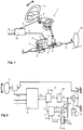
- an electromechanical power steering mechanism 1 is schematically illustrated with a steering shaft 2 connected to a steering wheel 3 for operation by the driver.
- the steering shaft 2 is coupled to a steering rack 5 via a gear pinion 6.
- Steering rack rods 4 are connected to the steering rack 5 and to steered wheels 30 of the motor vehicle.
- a rotation of the steering shaft 2 causes an axial displacement of the steering rack 5 by means of the gear pinion 6 which is connected to the steering shaft 2 in a torque-proof manner.
- an electric motor 7 mounted to the side of the rack housing drives a ball-screw mechanism 8 via a toothed rubber belt 9.
- Electric power assist is provided through a steering controller 10 and a power assist actuator 11 comprising the electric motor 7 and a motor controller 12.
- the steering controller 10 in the example receives signals representative of the vehicle velocity v and the torque T TS applied to the steering wheel by the vehicle operator.
- rotor position signals are generated within the electric motor 7 and provided to the steering controller 10.
- the controller 10 determines the target motor torque T d and provides the signal through to the motor controller 12, where the motor currents are calculated via PWM (pulse-width modulation).
- the electric motor 7 is a permanent magnet- excited motor.
- FIG. 2 shows a block diagram of the electrical structure of the electric power steering apparatus.
- the steering controller 10 receives signals representative of the vehicle velocity v and the torque T TS applied to the steering wheel by the vehicle operator and determines the target motor torque T d .
- the motor 7 generates a torque T which compensates the operator torque T TS .
- Estimated currents I1, est are calculated in a current estimation unit 15 via the voltages U2 determined by the motor controller 13 and a motor model unit 16.
- a diagnostic unit 17 receives the estimated currents I1, est , the measured motor angle ⁇ m from the Rotor Position Sensor 31 (RPS-sensor) and redundantly measured motor currents I1,1, I1,2 each measured by a current measurement unit 18, 19 and compares the estimated motor currents I1, est with the measured motor currents I1,1, I1,2. If a fault in one of the current measurement units is detected, the error-free current measurement unit can feed the steering assistance. For this purpose a current 12 is fed back into the main loop of the motor controller 13 as current feedback control.
- the electrical structure of the electric power steering apparatus 1 is shown in detail in figure 3 .
- the target-currents I d,d and I q,d are determined through a PI controller 20 and a unit 21.
- the target currents I d,d and I q,d are responsible for the determination of motor voltage conditions and motor torque. They are expressed in the rotating reference frame (d-q) fixed to the rotor of the motor 7.
- the target currents I d,d and I q,d are then transferred via current controllers 22, 23 into target voltages U q,d , U d,d .
- a coordinate transformation 24 converts the rotating two-dimensional d-q coordinate system into a coordinate system U ⁇ ,d , U ⁇ ,d fixed to the stator.
- the inverter 25 transforms the voltages into the three-dimensional coordinate system of the motor 7 and sensors transform the voltages into motor currents I U ,I V ,I W .
- the motor currents I U ,I V ,I W are measured redundantly in two current measurement units 18, 19.
- a coordinate transformation unit 260 the measured currents I U1 , I V1 , I W1 , I U2 , I V2 , I W2 are transformed, that means convertedin the rotational two-dimensional d-q coordinate system and fed into the diagnostic unit 17.
- the output voltages U U , U V , U W of the inverter 25 are transmitted to the current estimation unit 15 and transformed into estimated voltages U Uest , U Vest , U West and then fed to the motor model unit 16.
- the motor model unit 16 determines from the rotational angular velocity ⁇ of the rotor, the estimated voltages U Uest , U Vest , U West , the estimated winding temperature T Coil und possibly also the motor angle ⁇ an estimated current I1, est .
- the diagnostic unit 17 compares the estimated current I1, est with the measured currents I d1 , I q1 , I d2 , I q2 .
- the estimated current I1, est represents a target current from which the diagnostic unit 17 can determine, if an error occurred during current calculation between the motor controler 13 and the inverter 25.
- the diagnostic unit 17 compares the estimate currents I1, est , received from the motor model unit 16, and the two measured currents I d1,q1 and I d2,q2 from the current measurement units 18, 19. If a fault is detected in one of the current measurement units 18, 19, the steering assistance can be carried out with the signal from the error-free current measurement unit 18, 19. For this purpose a current 12 is fed back into the main loop of the motor control circuit behind the PI controller 20 and the unit 21 as current feedback control. In case that both current measurement units 18, 19 fail, steering assistance can be maintained for a certain time by feeding back an actual current 12 based on the estimate current I1, est .
- the servomotor is actuated by the control unit via a set of MOSFETs 26, wherein with three phase windings six MOSFETs 26 are provided in total.
- Each MOSFET 26 switches the assigned phase winding U, V, W to the on-board vehicle power-supply voltage or the earth potential. This occurs at a high frequency so that the temporal average value acts as the effective voltage in the phase windings U, V, W .
- Two shunts 27 are implemented on one thread each to calculate the motor currents.
- the output signal 1001 is transmitted into the current measurement units 18, 19. It is also possible, as shown in figure 5 , to implement one single shunt 27 on one thread to calculate the motor currents.
- the present invention provides an electromechanical motor vehicle power steering mechanism with a control apparatus, which feeds current to the electric motor even in the event of failure of the current measurement units.
- An estimated signal is used to decide which current measurement channel is wrong, while with the remaining signal assist can be maintained. If both signals fail, then the estimated value is used for limp aside steering assist, making it possible to steer the car to a safe place.
- the present invention increases the robustness of the steering system.
Landscapes
- Engineering & Computer Science (AREA)
- Chemical & Material Sciences (AREA)
- Combustion & Propulsion (AREA)
- Transportation (AREA)
- Mechanical Engineering (AREA)
- Power Engineering (AREA)
- Steering Control In Accordance With Driving Conditions (AREA)
- Control Of Ac Motors In General (AREA)
- Power Steering Mechanism (AREA)
Claims (9)
- Elektromechanischer Servolenkungsmechanismus eines Kraftfahrzeugs (1) zur Unterstützung der Lenkung eines Kraftfahrzeugs durch Übertragen eines von einem Elektromotor (7) erzeugten Drehmoments auf einen Lenkmechanismus, wobei der Mechanismus (1) umfasst:- eine Lenksteuerung (10), die Signale empfängt, welche wenigstens die Geschwindigkeit des Fahrzeugs (v) und das auf ein Lenkrad (3) abgegebene Drehmoment (TTS) sowie ein Rotorpositionssignal darstellen, um ein Soll-Motordrehmoment (Td) zu bestimmen,- eine Motorsteuerung (13), die das Soll-Motordrehmoment (Td) von der Lenksteuerung (10) empfängt und in Sollspannungen (Ua,d, Uβ,d) umsetzt, die in einem am Stator fixierten Koordinatensystem ausgedrückt werden, und- einen Motortreiber (14), der die Sollspannungen (Ua,d, Uβ,d) in Motorströme (IU, IV, IW) umwandelt- wenigstens eine Strommesseinheit (18, 19), die die Motorströme (IU, IV, IW) misst,wobei der Mechanismus (1) ferner umfasst: eine Stromschätzeinheit (15), die die Sollströme (Idest, Iqest=I1,est) schätzt, und eine Diagnoseeinheit (17), die die geschätzten Sollströme (Idest, Iqest=I1,est) mit gemessenen Strömen (Iq1, Id1=I1, Iq2, Id2=I2) vergleicht, die von den gemessenen Motorströmen (IU1, IV1, IW1, IU2, IV2, IW2) in ein zweidimensionales d-q-Koordinatensystem eines zweidimensionalen rotierenden Referenzrahmens (Idest, Iqest=I1) umgewandelt werden, der am Rotor des Motors (7) fixiert ist, um auftretende Störungen zu identifizieren und zu beheben,
dadurch gekennzeichnet, dass der Mechanismus (1) eine Koordinatenumwandlungseinheit (260) aufweist, die die gemessenen Motorströme (IU1, IV1, IW1, IU2, IV2, IW2) in gemessene Ströme (Iq1, Id1=I1, Iq2, Id2=I2) umwandelt, die in dem zweidimensionalen d-q-Koordinatensystem ausgedrückt werden, und
die Stromschätzeinheit (15) eine Motormodelleinheit (16) umfasst, die gespeist wird durch die geschätzten Spannungen (UUest, UVest, UWest), die auf den Spannungen (UU, UV, UW) basieren, die von einem Umrichter (25), der im Motortreiber (14) enthalten ist, ausgegeben werden. - Elektromechanischer Servolenkungsmechanismus eines Kraftfahrzeugs (1) gemäß Anspruch 1, dadurch gekennzeichnet, dass der Umrichter (25) die Sollspannungen (Ua,d, Uβ,d) in Dreiphasenspannungen (UU, UV, UW=U2) umwandelt.
- Elektromechanischer Servolenkungsmechanismus eines Kraftfahrzeugs (1) gemäß einem der vorstehenden Ansprüche, dadurch gekennzeichnet, dass der Mechanismus (1) zwei redundante Strommesseinheiten (18, 19) umfasst.
- Elektromechanischer Servolenkungsmechanismus eines Kraftfahrzeugs (1) gemäß Anspruch 1 oder 2, dadurch gekennzeichnet, dass die Motormodelleinheit (16) eine Koordinatentransformation (16') umfasst, die die geschätzten Motorströme in einen zweidimensionalen rotierenden Referenzrahmen (Idest, Iqest=I1) umsetzt, der am Rotor des Motors (7) fixiert ist.
- Elektromechanischer Servolenkungsmechanismus eines Kraftfahrzeugs (1) gemäß einem der Ansprüche 1 bis 4, dadurch gekennzeichnet, dass die Drehwinkelgeschwindigkeit (ω) des Rotors und die geschätzten Sollspannungen (UUest, UVest, UWest) sowie die geschätzte Wicklungstemperatur (TCoil) wenigstens Eingangsparameter für die Motormodelleinheit (16) sind.
- Elektromechanischer Servolenkungsmechanismus eines Kraftfahrzeugs (1) gemäß einem der vorstehenden Ansprüche, dadurch gekennzeichnet, dass der Motortreiber (14) zwei Nebenwiderstände umfasst, um die Motorströme (IU, IV, IW) zu rekonstruieren.
- Elektromechanischer Servolenkungsmechanismus eines Kraftfahrzeugs (1) gemäß einem der vorstehenden Ansprüche, dadurch gekennzeichnet, dass die Diagnoseeinheit (17) als Stromrückkopplungssteuerung fungiert, die einen tatsächlichen Strom (12) in die Hauptschleife der Motorsteuerungsschaltung zurückkoppelt.
- Verfahren zur Stromrückkopplungssteuerung in einem elektromechanischen Servolenkungsmechanismus eines Kraftfahrzeugs (1), wobei das Verfahren die folgenden Schritte umfasst:- Empfangen wenigstens von Signalen, welche die Geschwindigkeit des Fahrzeugs (v) und das auf ein Lenkrad (3) abgegebene Drehmoment (TTS) sowie ein Rotorpositionssignal darstellen- Bestimmen, auf Basis der empfangenen Signale, eines Soll-Motordrehmoments (Td), Umsetzen des Soll-Motordrehmoments (Td) in Sollspannungen (Ua,d, Uβ,d), die in einem am Stator fixierten Koordinatensystem ausgedrückt werden, und- Umwandeln der Sollspannungen (Ua,d, Uβ,d) in Motorströme (IU, IV, IW),- Messen der Motorströme in wenigstens einer Strommesseinheit (18, 19),• Schätzen der Sollströme (Idest, Iqest=I1,est) in einer Stromschätzeinheit (15),• Vergleichen der geschätzten Sollströme (Idest, Iqest=I1,est) mit den gemessenen Motorströmen (IU1, IV1, IW1, IU2, IV2, IW2) in einer Diagnoseeinheit (17), Rückkoppeln eines tatsächlichen Motorstroms (Iq,fb; Id,fb=I2) in die Hauptschleife,dadurch gekennzeichnet, dass
die Stromschätzeinheit (15) eine Motormodelleinheit (16) umfasst, die gespeist wird durch die geschätzten Spannungen (UUest, UVest, UWest), die auf den Spannungen (UU, UV, UW) basieren, die von einem Umrichter (25), der einem Motortreiber (14) des Servolenkungsmechanismus (1) zugeordnet ist, ausgegeben werden,
und die Drehwinkelgeschwindigkeit (ω) des Rotors,
die geschätzten Spannungen (UUest, UVest, Uwest), die auf den Sollspannungen (Ua,d, Uβ,d) basieren, und die geschätzte Wicklungstemperatur (TCoil) sind Eingabeparameter für die Motormodelleinheit (16). - Verfahren zur Stromrückkopplungssteuerung gemäß Anspruch 8, dadurch gekennzeichnet, dass der Mechanismus (1) zwei redundante Strommesseinheiten (18, 19) umfasst.
Priority Applications (1)
| Application Number | Priority Date | Filing Date | Title |
|---|---|---|---|
| PL16178296T PL3144205T3 (pl) | 2015-09-18 | 2016-07-07 | Wspomaganie kierowania typu limp aside z szacowanym prądem silnika |
Applications Claiming Priority (1)
| Application Number | Priority Date | Filing Date | Title |
|---|---|---|---|
| PCT/EP2015/071477 WO2017045729A1 (en) | 2015-09-18 | 2015-09-18 | Limp aside steering assist with estimated motor current |
Publications (2)
| Publication Number | Publication Date |
|---|---|
| EP3144205A1 EP3144205A1 (de) | 2017-03-22 |
| EP3144205B1 true EP3144205B1 (de) | 2018-03-14 |
Family
ID=54148524
Family Applications (1)
| Application Number | Title | Priority Date | Filing Date |
|---|---|---|---|
| EP16178296.6A Active EP3144205B1 (de) | 2015-09-18 | 2016-07-07 | Limp-aside-lenkunterstützung mit geschätztem motorstrom |
Country Status (6)
| Country | Link |
|---|---|
| US (1) | US10046792B2 (de) |
| EP (1) | EP3144205B1 (de) |
| CN (1) | CN107010099B (de) |
| ES (1) | ES2672049T3 (de) |
| PL (1) | PL3144205T3 (de) |
| WO (1) | WO2017045729A1 (de) |
Families Citing this family (9)
| Publication number | Priority date | Publication date | Assignee | Title |
|---|---|---|---|---|
| DE102015015148A1 (de) * | 2015-11-25 | 2017-06-01 | Thyssenkrupp Ag | Feedback-Aktuator für eine Lenkeinrichtung |
| EP3681785B1 (de) | 2017-09-13 | 2022-03-23 | thyssenkrupp Presta AG | Elektromechanisches servolenksystem mit nur gemessenem oder geschätztem lenkmomentsignal |
| GB201812587D0 (en) * | 2018-08-02 | 2018-09-19 | Trw Ltd | Improvements relating to multi lane motors |
| DE102018124906A1 (de) | 2018-10-09 | 2020-04-09 | Thyssenkrupp Ag | Redundante Steuereinheit für eine Kraftfahrzeuglenkung |
| DE102021205208A1 (de) | 2021-05-21 | 2022-11-24 | Thyssenkrupp Ag | Elektromechanisches Lenksystem mit Schutzschaltung bei Spannungsabfall sowie Verfahren zum Betreiben eines solchen Lenksystems |
| CN113788063B (zh) * | 2021-09-03 | 2022-07-12 | 湖南东嘉智能科技有限公司 | 电动助力转向控制系统及其电流检测方法 |
| DE102022203087A1 (de) | 2022-03-29 | 2023-10-05 | Thyssenkrupp Ag | Verfahren und Schaltungsanordnung zum schutzschalterlosen Betreiben eines Doppelwicklungs-Drehstrommotors sowie elektromechanisches Lenksystem mit einem Doppelwicklungs-Drehstrommotor und einer Schaltungsanordnung |
| BE1031001B1 (de) | 2022-10-28 | 2024-06-04 | Thyssenkrupp Presta Ag | Elektromechanisches Lenksystem mit einem Doppelwicklungs-Drehstrommotor und Verfahren zum Betreiben eines Doppelwicklungs-Drehstrommotors |
| BE1032205B1 (de) | 2023-12-06 | 2025-07-07 | Thyssenkrupp Presta Ag | Elektromechanisches Lenksystem und Verfahren zum Betreiben eines elektromechanischen Lenksystems mit Notabschaltung des Aktuators |
Family Cites Families (7)
| Publication number | Priority date | Publication date | Assignee | Title |
|---|---|---|---|---|
| JP4498353B2 (ja) | 2004-03-19 | 2010-07-07 | 三菱電機株式会社 | 電動機制御装置 |
| JP2006069352A (ja) * | 2004-09-01 | 2006-03-16 | Favess Co Ltd | 電動パワーステアリング装置 |
| GB0526276D0 (en) * | 2005-12-23 | 2006-02-01 | Trw Ltd | Electric motor control |
| JP5233178B2 (ja) * | 2007-06-14 | 2013-07-10 | 株式会社ジェイテクト | モータ制御装置及び電動パワーステアリング装置 |
| EP2015445B1 (de) * | 2007-06-20 | 2011-12-14 | Jtekt Corporation | Motorensteuergerät und elektrische Servolenkungsvorrichtung |
| JP5365701B2 (ja) * | 2009-12-25 | 2013-12-11 | トヨタ自動車株式会社 | 電動パワーステアリング装置 |
| WO2012093679A1 (ja) * | 2011-01-07 | 2012-07-12 | 本田技研工業株式会社 | 電動パワーステアリング装置 |
-
2015
- 2015-09-18 WO PCT/EP2015/071477 patent/WO2017045729A1/en not_active Ceased
-
2016
- 2016-07-07 EP EP16178296.6A patent/EP3144205B1/de active Active
- 2016-07-07 ES ES16178296.6T patent/ES2672049T3/es active Active
- 2016-07-07 PL PL16178296T patent/PL3144205T3/pl unknown
- 2016-09-09 CN CN201610815677.XA patent/CN107010099B/zh active Active
- 2016-09-19 US US15/269,359 patent/US10046792B2/en active Active
Non-Patent Citations (1)
| Title |
|---|
| None * |
Also Published As
| Publication number | Publication date |
|---|---|
| US10046792B2 (en) | 2018-08-14 |
| ES2672049T3 (es) | 2018-06-12 |
| WO2017045729A1 (en) | 2017-03-23 |
| PL3144205T3 (pl) | 2018-09-28 |
| EP3144205A1 (de) | 2017-03-22 |
| CN107010099B (zh) | 2020-06-09 |
| US20170080971A1 (en) | 2017-03-23 |
| CN107010099A (zh) | 2017-08-04 |
Similar Documents
| Publication | Publication Date | Title |
|---|---|---|
| US10046792B2 (en) | Limp aside steering assist with estimated motor current | |
| US11084523B2 (en) | Vehicle-mounted device actuator and power steering device | |
| JP6635128B2 (ja) | 電動パワーステアリング装置 | |
| EP2599687B1 (de) | Fahrzeuglenkungssystem | |
| US20050159866A1 (en) | Steering control device and steering control method of motor vehicle | |
| US8892296B2 (en) | Power state diagnosis method and apparatus | |
| JP6061117B2 (ja) | 電動パワーステアリング装置 | |
| US20200047791A1 (en) | Vehicle control apparatus | |
| US11453435B2 (en) | Vehicle control apparatus | |
| JP2020040437A (ja) | パワーステアリング装置 | |
| US7483796B2 (en) | Method and apparatus for determining faults in an electric assist steering system | |
| JP6024504B2 (ja) | ステアリング制御装置、ステアリング制御方法 | |
| JP6180959B2 (ja) | 電動パワーステアリング装置、レゾルバ故障検出装置、レゾルバ故障検出方法 | |
| JP2020078184A (ja) | 電動パワーステアリング装置 |
Legal Events
| Date | Code | Title | Description |
|---|---|---|---|
| PUAI | Public reference made under article 153(3) epc to a published international application that has entered the european phase |
Free format text: ORIGINAL CODE: 0009012 |
|
| AK | Designated contracting states |
Kind code of ref document: A1 Designated state(s): AL AT BE BG CH CY CZ DE DK EE ES FI FR GB GR HR HU IE IS IT LI LT LU LV MC MK MT NL NO PL PT RO RS SE SI SK SM TR |
|
| AX | Request for extension of the european patent |
Extension state: BA ME |
|
| RAP1 | Party data changed (applicant data changed or rights of an application transferred) |
Owner name: THYSSENKRUPP PRESTA AG Owner name: THYSSENKRUPP AG |
|
| 17P | Request for examination filed |
Effective date: 20170901 |
|
| RBV | Designated contracting states (corrected) |
Designated state(s): AL AT BE BG CH CY CZ DE DK EE ES FI FR GB GR HR HU IE IS IT LI LT LU LV MC MK MT NL NO PL PT RO RS SE SI SK SM TR |
|
| GRAP | Despatch of communication of intention to grant a patent |
Free format text: ORIGINAL CODE: EPIDOSNIGR1 |
|
| INTG | Intention to grant announced |
Effective date: 20171113 |
|
| GRAS | Grant fee paid |
Free format text: ORIGINAL CODE: EPIDOSNIGR3 |
|
| GRAA | (expected) grant |
Free format text: ORIGINAL CODE: 0009210 |
|
| AK | Designated contracting states |
Kind code of ref document: B1 Designated state(s): AL AT BE BG CH CY CZ DE DK EE ES FI FR GB GR HR HU IE IS IT LI LT LU LV MC MK MT NL NO PL PT RO RS SE SI SK SM TR |
|
| REG | Reference to a national code |
Ref country code: GB Ref legal event code: FG4D |
|
| REG | Reference to a national code |
Ref country code: CH Ref legal event code: EP Ref country code: AT Ref legal event code: REF Ref document number: 978590 Country of ref document: AT Kind code of ref document: T Effective date: 20180315 |
|
| REG | Reference to a national code |
Ref country code: IE Ref legal event code: FG4D |
|
| REG | Reference to a national code |
Ref country code: DE Ref legal event code: R096 Ref document number: 602016001979 Country of ref document: DE |
|
| REG | Reference to a national code |
Ref country code: ES Ref legal event code: FG2A Ref document number: 2672049 Country of ref document: ES Kind code of ref document: T3 Effective date: 20180612 |
|
| REG | Reference to a national code |
Ref country code: NL Ref legal event code: MP Effective date: 20180314 |
|
| REG | Reference to a national code |
Ref country code: LT Ref legal event code: MG4D |
|
| REG | Reference to a national code |
Ref country code: FR Ref legal event code: PLFP Year of fee payment: 3 |
|
| PG25 | Lapsed in a contracting state [announced via postgrant information from national office to epo] |
Ref country code: HR Free format text: LAPSE BECAUSE OF FAILURE TO SUBMIT A TRANSLATION OF THE DESCRIPTION OR TO PAY THE FEE WITHIN THE PRESCRIBED TIME-LIMIT Effective date: 20180314 Ref country code: CY Free format text: LAPSE BECAUSE OF FAILURE TO SUBMIT A TRANSLATION OF THE DESCRIPTION OR TO PAY THE FEE WITHIN THE PRESCRIBED TIME-LIMIT Effective date: 20180314 Ref country code: LT Free format text: LAPSE BECAUSE OF FAILURE TO SUBMIT A TRANSLATION OF THE DESCRIPTION OR TO PAY THE FEE WITHIN THE PRESCRIBED TIME-LIMIT Effective date: 20180314 Ref country code: NO Free format text: LAPSE BECAUSE OF FAILURE TO SUBMIT A TRANSLATION OF THE DESCRIPTION OR TO PAY THE FEE WITHIN THE PRESCRIBED TIME-LIMIT Effective date: 20180614 Ref country code: FI Free format text: LAPSE BECAUSE OF FAILURE TO SUBMIT A TRANSLATION OF THE DESCRIPTION OR TO PAY THE FEE WITHIN THE PRESCRIBED TIME-LIMIT Effective date: 20180314 |
|
| REG | Reference to a national code |
Ref country code: AT Ref legal event code: MK05 Ref document number: 978590 Country of ref document: AT Kind code of ref document: T Effective date: 20180314 |
|
| PG25 | Lapsed in a contracting state [announced via postgrant information from national office to epo] |
Ref country code: SE Free format text: LAPSE BECAUSE OF FAILURE TO SUBMIT A TRANSLATION OF THE DESCRIPTION OR TO PAY THE FEE WITHIN THE PRESCRIBED TIME-LIMIT Effective date: 20180314 Ref country code: LV Free format text: LAPSE BECAUSE OF FAILURE TO SUBMIT A TRANSLATION OF THE DESCRIPTION OR TO PAY THE FEE WITHIN THE PRESCRIBED TIME-LIMIT Effective date: 20180314 Ref country code: GR Free format text: LAPSE BECAUSE OF FAILURE TO SUBMIT A TRANSLATION OF THE DESCRIPTION OR TO PAY THE FEE WITHIN THE PRESCRIBED TIME-LIMIT Effective date: 20180615 Ref country code: RS Free format text: LAPSE BECAUSE OF FAILURE TO SUBMIT A TRANSLATION OF THE DESCRIPTION OR TO PAY THE FEE WITHIN THE PRESCRIBED TIME-LIMIT Effective date: 20180314 Ref country code: BG Free format text: LAPSE BECAUSE OF FAILURE TO SUBMIT A TRANSLATION OF THE DESCRIPTION OR TO PAY THE FEE WITHIN THE PRESCRIBED TIME-LIMIT Effective date: 20180614 |
|
| PG25 | Lapsed in a contracting state [announced via postgrant information from national office to epo] |
Ref country code: AL Free format text: LAPSE BECAUSE OF FAILURE TO SUBMIT A TRANSLATION OF THE DESCRIPTION OR TO PAY THE FEE WITHIN THE PRESCRIBED TIME-LIMIT Effective date: 20180314 Ref country code: EE Free format text: LAPSE BECAUSE OF FAILURE TO SUBMIT A TRANSLATION OF THE DESCRIPTION OR TO PAY THE FEE WITHIN THE PRESCRIBED TIME-LIMIT Effective date: 20180314 Ref country code: NL Free format text: LAPSE BECAUSE OF FAILURE TO SUBMIT A TRANSLATION OF THE DESCRIPTION OR TO PAY THE FEE WITHIN THE PRESCRIBED TIME-LIMIT Effective date: 20180314 Ref country code: RO Free format text: LAPSE BECAUSE OF FAILURE TO SUBMIT A TRANSLATION OF THE DESCRIPTION OR TO PAY THE FEE WITHIN THE PRESCRIBED TIME-LIMIT Effective date: 20180314 |
|
| PG25 | Lapsed in a contracting state [announced via postgrant information from national office to epo] |
Ref country code: SM Free format text: LAPSE BECAUSE OF FAILURE TO SUBMIT A TRANSLATION OF THE DESCRIPTION OR TO PAY THE FEE WITHIN THE PRESCRIBED TIME-LIMIT Effective date: 20180314 Ref country code: AT Free format text: LAPSE BECAUSE OF FAILURE TO SUBMIT A TRANSLATION OF THE DESCRIPTION OR TO PAY THE FEE WITHIN THE PRESCRIBED TIME-LIMIT Effective date: 20180314 Ref country code: SK Free format text: LAPSE BECAUSE OF FAILURE TO SUBMIT A TRANSLATION OF THE DESCRIPTION OR TO PAY THE FEE WITHIN THE PRESCRIBED TIME-LIMIT Effective date: 20180314 |
|
| REG | Reference to a national code |
Ref country code: DE Ref legal event code: R097 Ref document number: 602016001979 Country of ref document: DE |
|
| PG25 | Lapsed in a contracting state [announced via postgrant information from national office to epo] |
Ref country code: PT Free format text: LAPSE BECAUSE OF FAILURE TO SUBMIT A TRANSLATION OF THE DESCRIPTION OR TO PAY THE FEE WITHIN THE PRESCRIBED TIME-LIMIT Effective date: 20180716 |
|
| PLBE | No opposition filed within time limit |
Free format text: ORIGINAL CODE: 0009261 |
|
| STAA | Information on the status of an ep patent application or granted ep patent |
Free format text: STATUS: NO OPPOSITION FILED WITHIN TIME LIMIT |
|
| PG25 | Lapsed in a contracting state [announced via postgrant information from national office to epo] |
Ref country code: DK Free format text: LAPSE BECAUSE OF FAILURE TO SUBMIT A TRANSLATION OF THE DESCRIPTION OR TO PAY THE FEE WITHIN THE PRESCRIBED TIME-LIMIT Effective date: 20180314 |
|
| 26N | No opposition filed |
Effective date: 20181217 |
|
| PG25 | Lapsed in a contracting state [announced via postgrant information from national office to epo] |
Ref country code: SI Free format text: LAPSE BECAUSE OF FAILURE TO SUBMIT A TRANSLATION OF THE DESCRIPTION OR TO PAY THE FEE WITHIN THE PRESCRIBED TIME-LIMIT Effective date: 20180314 |
|
| PG25 | Lapsed in a contracting state [announced via postgrant information from national office to epo] |
Ref country code: MC Free format text: LAPSE BECAUSE OF FAILURE TO SUBMIT A TRANSLATION OF THE DESCRIPTION OR TO PAY THE FEE WITHIN THE PRESCRIBED TIME-LIMIT Effective date: 20180314 Ref country code: LU Free format text: LAPSE BECAUSE OF NON-PAYMENT OF DUE FEES Effective date: 20180707 |
|
| REG | Reference to a national code |
Ref country code: BE Ref legal event code: MM Effective date: 20180731 |
|
| REG | Reference to a national code |
Ref country code: IE Ref legal event code: MM4A |
|
| PG25 | Lapsed in a contracting state [announced via postgrant information from national office to epo] |
Ref country code: IE Free format text: LAPSE BECAUSE OF NON-PAYMENT OF DUE FEES Effective date: 20180707 |
|
| PG25 | Lapsed in a contracting state [announced via postgrant information from national office to epo] |
Ref country code: BE Free format text: LAPSE BECAUSE OF NON-PAYMENT OF DUE FEES Effective date: 20180731 |
|
| PG25 | Lapsed in a contracting state [announced via postgrant information from national office to epo] |
Ref country code: MT Free format text: LAPSE BECAUSE OF NON-PAYMENT OF DUE FEES Effective date: 20180707 |
|
| REG | Reference to a national code |
Ref country code: CH Ref legal event code: PL |
|
| PG25 | Lapsed in a contracting state [announced via postgrant information from national office to epo] |
Ref country code: TR Free format text: LAPSE BECAUSE OF FAILURE TO SUBMIT A TRANSLATION OF THE DESCRIPTION OR TO PAY THE FEE WITHIN THE PRESCRIBED TIME-LIMIT Effective date: 20180314 |
|
| PG25 | Lapsed in a contracting state [announced via postgrant information from national office to epo] |
Ref country code: LI Free format text: LAPSE BECAUSE OF NON-PAYMENT OF DUE FEES Effective date: 20190731 Ref country code: CH Free format text: LAPSE BECAUSE OF NON-PAYMENT OF DUE FEES Effective date: 20190731 |
|
| PG25 | Lapsed in a contracting state [announced via postgrant information from national office to epo] |
Ref country code: HU Free format text: LAPSE BECAUSE OF FAILURE TO SUBMIT A TRANSLATION OF THE DESCRIPTION OR TO PAY THE FEE WITHIN THE PRESCRIBED TIME-LIMIT; INVALID AB INITIO Effective date: 20160707 Ref country code: MK Free format text: LAPSE BECAUSE OF NON-PAYMENT OF DUE FEES Effective date: 20180314 |
|
| PG25 | Lapsed in a contracting state [announced via postgrant information from national office to epo] |
Ref country code: IS Free format text: LAPSE BECAUSE OF FAILURE TO SUBMIT A TRANSLATION OF THE DESCRIPTION OR TO PAY THE FEE WITHIN THE PRESCRIBED TIME-LIMIT Effective date: 20180714 |
|
| REG | Reference to a national code |
Ref country code: DE Ref legal event code: R081 Ref document number: 602016001979 Country of ref document: DE Owner name: THYSSENKRUPP PRESTA AKTIENGESELLSCHAFT, LI Free format text: FORMER OWNERS: THYSSENKRUPP AG, 45143 ESSEN, DE; THYSSENKRUPP PRESTA AG, ESCHEN, LI Ref country code: DE Ref legal event code: R081 Ref document number: 602016001979 Country of ref document: DE Owner name: THYSSENKRUPP AG, DE Free format text: FORMER OWNERS: THYSSENKRUPP AG, 45143 ESSEN, DE; THYSSENKRUPP PRESTA AG, ESCHEN, LI |
|
| PGFP | Annual fee paid to national office [announced via postgrant information from national office to epo] |
Ref country code: IT Payment date: 20230724 Year of fee payment: 8 Ref country code: ES Payment date: 20230926 Year of fee payment: 8 Ref country code: CZ Payment date: 20230703 Year of fee payment: 8 |
|
| PGFP | Annual fee paid to national office [announced via postgrant information from national office to epo] |
Ref country code: PL Payment date: 20230703 Year of fee payment: 8 |
|
| PG25 | Lapsed in a contracting state [announced via postgrant information from national office to epo] |
Ref country code: CZ Free format text: LAPSE BECAUSE OF NON-PAYMENT OF DUE FEES Effective date: 20240707 |
|
| PG25 | Lapsed in a contracting state [announced via postgrant information from national office to epo] |
Ref country code: CZ Free format text: LAPSE BECAUSE OF NON-PAYMENT OF DUE FEES Effective date: 20240707 |
|
| PG25 | Lapsed in a contracting state [announced via postgrant information from national office to epo] |
Ref country code: IT Free format text: LAPSE BECAUSE OF NON-PAYMENT OF DUE FEES Effective date: 20240707 |
|
| REG | Reference to a national code |
Ref country code: ES Ref legal event code: FD2A Effective date: 20250828 |
|
| PG25 | Lapsed in a contracting state [announced via postgrant information from national office to epo] |
Ref country code: ES Free format text: LAPSE BECAUSE OF NON-PAYMENT OF DUE FEES Effective date: 20240708 |
|
| PGFP | Annual fee paid to national office [announced via postgrant information from national office to epo] |
Ref country code: DE Payment date: 20250722 Year of fee payment: 10 |
|
| PGFP | Annual fee paid to national office [announced via postgrant information from national office to epo] |
Ref country code: GB Payment date: 20250722 Year of fee payment: 10 |
|
| PGFP | Annual fee paid to national office [announced via postgrant information from national office to epo] |
Ref country code: FR Payment date: 20250725 Year of fee payment: 10 |
|
| PG25 | Lapsed in a contracting state [announced via postgrant information from national office to epo] |
Ref country code: PL Free format text: LAPSE BECAUSE OF NON-PAYMENT OF DUE FEES Effective date: 20240707 |