EP3144108B1 - Attachment for a hand tool - Google Patents
Attachment for a hand tool Download PDFInfo
- Publication number
- EP3144108B1 EP3144108B1 EP16186838.5A EP16186838A EP3144108B1 EP 3144108 B1 EP3144108 B1 EP 3144108B1 EP 16186838 A EP16186838 A EP 16186838A EP 3144108 B1 EP3144108 B1 EP 3144108B1
- Authority
- EP
- European Patent Office
- Prior art keywords
- attachment
- receiving sleeve
- shaft
- unit
- transmission
- Prior art date
- Legal status (The legal status is an assumption and is not a legal conclusion. Google has not performed a legal analysis and makes no representation as to the accuracy of the status listed.)
- Active
Links
- 238000003756 stirring Methods 0.000 claims description 40
- 230000008878 coupling Effects 0.000 claims description 32
- 238000010168 coupling process Methods 0.000 claims description 32
- 238000005859 coupling reaction Methods 0.000 claims description 32
- 230000005540 biological transmission Effects 0.000 claims description 22
- 230000002265 prevention Effects 0.000 claims 1
- 239000008267 milk Substances 0.000 description 5
- 210000004080 milk Anatomy 0.000 description 5
- 235000013336 milk Nutrition 0.000 description 5
- 238000003780 insertion Methods 0.000 description 3
- 230000037431 insertion Effects 0.000 description 3
- 238000007373 indentation Methods 0.000 description 2
- 238000000034 method Methods 0.000 description 2
- 230000008569 process Effects 0.000 description 2
- 230000009471 action Effects 0.000 description 1
- 230000008901 benefit Effects 0.000 description 1
- 238000010276 construction Methods 0.000 description 1
- 238000011161 development Methods 0.000 description 1
- 230000018109 developmental process Effects 0.000 description 1
- 230000035622 drinking Effects 0.000 description 1
- 230000000694 effects Effects 0.000 description 1
- 238000005187 foaming Methods 0.000 description 1
- 230000003993 interaction Effects 0.000 description 1
- 230000007246 mechanism Effects 0.000 description 1
- 239000013589 supplement Substances 0.000 description 1
Images


Classifications
-
- B—PERFORMING OPERATIONS; TRANSPORTING
- B25—HAND TOOLS; PORTABLE POWER-DRIVEN TOOLS; MANIPULATORS
- B25F—COMBINATION OR MULTI-PURPOSE TOOLS NOT OTHERWISE PROVIDED FOR; DETAILS OR COMPONENTS OF PORTABLE POWER-DRIVEN TOOLS NOT PARTICULARLY RELATED TO THE OPERATIONS PERFORMED AND NOT OTHERWISE PROVIDED FOR
- B25F3/00—Associations of tools for different working operations with one portable power-drive means; Adapters therefor
Definitions
- a handheld power tool accessory device which connects an output shaft of a handheld power tool to a drive shaft of the accessory device via at least one coupling means and has at least one functional unit with at least one stirring element.
- Attachment of the accessory device to the hand-held power tool as described above limits the functionality and usability of the accessory device.
- An article according to the preamble of claim 1 is out DE 10 2012 203 425 A1 famous.
- the invention provides an attachment for a handheld power tool that ensures reliable functioning of the stirring unit.
- the essay is intended to extend the range of functions of the handheld power tool to new areas of application.
- the invention relates to an attachment, in particular an attachment for a hand-held power tool, which has an agitator unit with at least one agitator element and an agitator shaft.
- the attachment also includes a coupling unit for torque transmission from the handheld power tool to the stirring unit, the coupling unit having at least one drive shaft which can be coupled in a torque-proof manner to an output shaft of the handheld power tool.
- the invention Essay on a locking unit for locking the attachment with a housing of the hand tool.
- the locking unit makes it possible to reliably and releasably lock the attachment to a housing of the hand-held power tool.
- the locking can be designed to be non-positive and/or positive. Locking with the housing of the hand-held power tool preferably takes place via corresponding locking elements.
- the locking unit has at least one locking element for axially and/or rotationally locking the attachment on a housing of the hand-held power tool.
- the locking unit can have, for example, at least one locking element for axial locking and at least one, in particular separately designed, locking element for anti-rotation locking.
- the locking element for axial securing is designed as a spring element which engages in a corresponding locking element, for example a recess or a groove, on the housing of the hand-held power tool.
- the locking element to prevent rotation can be designed, for example, as a toothed ring that engages in a corresponding toothed ring on the housing of the hand-held power tool.
- the housing of the hand-held power tool has at least one locking element for axial securing, preferably an annular groove, which interacts with at least one corresponding locking element in the locking unit of the attachment, preferably an annular spring.
- the housing comprises at least one locking element for anti-rotation, preferably a toothed ring, which interacts with at least one corresponding locking element in the locking unit of the attachment, preferably also a toothed ring.
- the attachment can be adapted to the housing of the hand-held power tool around the main axis in any angular steps of the locking unit.
- Alternative embodiments for a locking element for axial security and for a locking element for anti-rotation are also possible.
- the coupling unit is designed to couple the output shaft of the handheld power tool to the agitator shaft of the agitator unit for torque transmission.
- the coupling unit has a housing and a drive shaft, wherein the drive shaft is coupled in a torque-proof manner to the agitator shaft and can, for example, be designed in one piece with the agitator shaft.
- the end piece of the drive shaft can have a coupling geometry which advantageously corresponds to a coupling geometry of the output shaft of the hand-held power tool.
- the coupling geometry of the drive shaft of the attachment is formed on the outer contour of the drive shaft, the corresponding coupling geometry of the output shaft of the handheld power tool is advantageously formed in a recess of the output shaft of the handheld power tool and vice versa.
- the end piece of the drive shaft is, in particular, designed to be polygonal, preferably hexagonal, and is designed to correspond to the recess in the tool holder of the hand-held power tool.
- the construction of the coupling unit is designed in such a way that the agitator shaft can rotate in both directions, thus preventing incorrect operation by the user.
- the stirring unit has a stirring shaft, which can in particular be designed in the form of a rod and comprises a stirring element for frothing milk.
- the length of the stirring unit does not affect the functioning of the invention, but advantageously it corresponds at least to the depth of commercially available drinking vessels.
- the stirring element is preferably designed as a spiral spring.
- Other embodiments for the stirring element are, in particular, rotor blades or a propeller-like disk.
- the advantage of the spiral spring is that the foaming efficiency is independent of the direction of rotation of the agitator shaft.
- the coupling unit has a gear with at least one gear stage for increasing the speed of the agitator shaft relative to the speed of the drive shaft.
- the gearbox makes it possible to adjust the rotation speed of the stirring unit to the task at hand.
- the gearing is preferably designed for very high speeds of the agitator shaft (approx. 4000 rpm), the very high speeds being advantageous for frothing milk.
- the transmission ratio is 1:20, for example.
- the gear is designed as a planetary gear which includes at least one stage.
- the gear is provided as a two-stage planetary gear.
- the use of a planetary gear enables a compact design of the attachment.
- the drive shaft of the attachment can in particular be designed in one piece with the planet carrier of the first stage.
- the attachment has an accessory interface unit that establishes a detachable, non-positive and/or positive connection of the coupling unit with the stirring unit in the axial and rotational direction.
- the range of functions of the attachment is sensibly expanded by the accessory interface unit.
- the accessory interface unit provides a detachable, non-rotatable connection between the stirring unit and the coupling unit, which makes it possible in particular to detach the stirring unit from the attachment, in particular in order to clean the stirring unit.
- the accessory interface unit may be at least partially integral with the transmission of the attachment.
- the agitator shaft of the agitator unit can advantageously be releasably connected to an output element of the transmission.
- the agitator shaft can dip deeper into the attachment, which allows the agitator shaft to be radially supported over a longer axial area. This measure can significantly improve the concentricity properties of the agitator shaft.
- the accessory interface unit has a receiving sleeve with a receiving opening for receiving the agitator shaft, in which the agitator shaft is radially guided.
- the agitator shaft can be detachably connected to the coupling unit by means of the receiving sleeve.
- the receiving sleeve has in particular at least one element for the non-positive and/or positive connection with the stirring unit.
- the receiving opening can in particular be designed as a receiving bore.
- the receiving sleeve can preferably be rotatably mounted in a bearing.
- the receiving sleeve is in particular non-rotatably connected to an output element of the transmission, in particular a sun gear of a planetary gear.
- Torque is transmitted between the drive shaft of the attachment and the receiving sleeve by means of a non-rotatable connection of the receiving sleeve to the gear mechanism.
- the receiving sleeve can in particular be formed in one piece with an output element of the transmission.
- the receiving sleeve can be designed in two pieces with an output element of the transmission and, in particular, can be pressed with it.
- the receiving sleeve is designed as a collet for the detachable connection of the agitator shaft to the receiving sleeve.
- the receiving sleeve At its open end, has in particular at least one longitudinal slot.
- the receiving sleeve can be provided with an outer cone. The detachable connection takes place in particular via a non-positive axial and rotational lock.
- At least one clamping sleeve corresponding to the outer cone is provided on an outer cone of the receiving sleeve.
- the inner surface of the clamping sleeve is preferably pressed against the outer cone of the clamping sleeve by at least one spring.
- the axial support of the at least one spring takes place in particular on a support element. The spring is thus clamped between the clamping sleeve and the support element.
- the support element is designed as a shoulder.
- the shoulder can be arranged in particular on the outer surface of the receiving sleeve.
- the inner surface of the clamping sleeve is preferably provided as an inner cone.
- Spring force causes the inner cone of the clamping sleeve to move axially against the outer cone of the receiving sleeve.
- a radial force is exerted on the receiving sleeve.
- the radial force provides a friction fit of the accessory interface unit with the agitator shaft.
- the arrangement of the clamping sleeve and the support element on the receiving sleeve is chosen so that at the parts under spring force do not rotate relative to one another, with the result that wear is reduced.
- the support element is preferably designed as a disk.
- the disc acts in particular on the bearing of the receiving sleeve.
- the bearing of the receiving sleeve is preferably designed in such a way that it protrudes from the housing of the attachment at the end.
- the spring preferably takes over the rotary movement of the receiving sleeve. A possible rotation of the disk during operation is determined by the friction conditions. If the friction between the disc and the spring is greater than the friction between the disc and the thrust bearing, the disc will rotate during operation and vice versa.
- the support element can be designed in one piece with the bearing of the receiving sleeve.
- the receiving sleeve is connected in a rotationally fixed manner to in particular an output element of the transmission via a connecting shaft in particular.
- the connecting shaft is provided for torque transmission from the drive shaft of the attachment to the receiving sleeve.
- the receiving sleeve is firmly connected to the connecting shaft, in particular pressed.
- the receiving sleeve can in particular be located outside the housing of the attachment.
- the receiving sleeve has in particular at least one radially movable locking element for axially and/or rotationally locking the agitator shaft in the receiving opening of the receiving sleeve.
- the at least one radially movable locking element of the receiving sleeve is provided in particular for the non-positive and/or positive connection in the axial and/or rotational direction of the agitator shaft with the receiving sleeve.
- Different shapes are possible for the locking element, in particular a spherical or conical shape.
- the at least one locking element is preferably loaded in particular by a spring and/or a screw.
- the at least one, radially movable Locking element can be provided for axial securing. In this embodiment, an additional anti-rotation device is therefore necessary.
- the receiving sleeve has in particular at least one anti-rotation element for preventing the agitator shaft from rotating.
- the anti-twist element is provided to prevent the agitator shaft from rotating in the receiving opening of the receiving sleeve, in particular by positive locking in the direction of rotation.
- a longitudinal groove or a rail in the receiving sleeve can act as an anti-rotation element, with a corresponding locking element being formed on the agitator shaft.
- the agitator shaft has in particular at least one locking element for axial and/or rotational security, which corresponds to the at least one locking element and/or the at least one anti-rotation element of the accessory interface unit.
- the at least one locking element on the agitator shaft causes a non-positive and/or positive connection in the axial and/or rotational direction between the agitator shaft and the accommodating sleeve with the locking element and/or the anti-rotation element of the accommodating sleeve.
- the locking element of the agitator shaft is designed in particular as a bulge. Inserting the agitator shaft into the receiving opening results in a form fit of the bulge with the previously described longitudinal groove of the receiving sleeve, which causes a rotation lock. Furthermore, when the agitator shaft is inserted into the receiving opening when the bulge of the agitator shaft meets the radially movable locking element of the receiving sleeve, the latter is moved radially outwards. As it is inserted further, the bulge moves past the locking element, which means that the locking element snaps back again and thus causes the agitator shaft to be locked axially by means of a force fit.
- At least one locking element on the agitator shaft only cause an axial or rotational lock
- at least one additional Locking element provided on the agitator shaft so that both locking elements together cause an axial and rotational security.
- a further embodiment of the locking element is in particular an indentation.
- the invention also relates to an electrical device, in particular a hand-held power tool, with the attachment according to the invention.
- the hand-held power tool includes at least one housing, which includes a drive unit with a motor.
- the drive unit can also have a gear.
- the housing of the handheld power tool can include a grip area.
- the housing can include an operating switch for switching the hand-held power tool on and off.
- the hand-held power tool is an implement that can be coupled to an application tool, such as a bit, a drill, etc.
- the application tool can be coupled in a torque-proof manner to an output shaft of the implement.
- the insertion tool can be coupled directly to the output shaft of the hand-held power tool.
- a direct coupling is to be understood in particular as meaning that the output shaft protrudes from the housing of the hand-held power tool and is designed as a tool holder.
- the tool holder can, for example, have a recess which is designed to accommodate the insertion tool.
- the cross section of the recess advantageously has a coupling geometry for torque transmission.
- the coupling geometry can, for example, be in the form of a polygon, in particular a hexagon. Other coupling geometries such as circular, etc. are also conceivable.
- the recess can additionally have grooves or wings, which are arranged at least partially along its length. However, other geometric shapes or a combination of two or more geometric shapes, such as a hexagon and a circle, are also conceivable.
- all the main components are preferably arranged in the axial direction along the main axis of the hand-held power tool. This enables a slim, symmetrical and easy-to-install design.
- the accessory interface unit can be used to add useful functions to the attachment.
- the powerful motor of the hand tool results in an even load and no-load speed of the stirring unit.
- Replacing the stirring element of the stirring unit is the basis for new functions.
- Stirring elements such as those already used in connection with stirrers or hand blenders are conceivable, preferably a whisk, a dough hook or a mixer foot.
- FIGs 1 to 5 are five embodiments of the attachment 200, 300, 400, 500, 600 according to the invention (see 1 , 2 , 3 , 4 , 5 ) shown.
- Fig. 1a a perspective view of a section of a handheld power tool 100 is shown, which is suitable for receiving the attachment 200, 300, 400, 500, 600.
- the handheld power tool 100 shown is, for example, a screwdriver.
- the hand-held power tool 100 comprises a housing 110 and an output shaft 120 which has a polygonal recess 122 for receiving an insert tool, e.g. B. a screwdriver bit (not shown) has.
- the handheld power tool 100 can be used as such.
- the housing 110 comprises locking elements on the front side, shown by way of example as an annular groove 112 and toothed ring 114, for locking one of the attachments 200, 300, 400, 500, 600.
- a perspective view of the attachment 200 according to the invention is shown, which has a locking unit 210, a coupling unit 220 and a stirring unit 230 in the axial direction.
- the coupling unit 220 includes a housing 222 and a gear 224.
- the locking unit 210 is used to lock the Attachment 200 to the housing 110 of the handheld power tool 100 via locking elements for a latching connection, for example as an annular spring 212 and toothed ring 214 ( 1c ) executed. Reliable axial and rotational locking of the handheld power tool 100 with the attachment 200 is achieved through the interaction of the locking elements 212, 214 of the attachment 200 and the locking elements 112, 114 of the handheld power tool 100 that correspond to them.
- the stirring unit 230 comprises an axially rod-shaped stirring shaft 232 and a stirring element 234 arranged on the front side, for example in the form of a spiral spring, which is suitable for frothing milk.
- the elements of the attachment 200 are listed in such a way that the milk frothing function is independent of the direction of rotation of the output shaft 120 of the hand-held power tool 100 .
- a longitudinal section of the preferred embodiment of the attachment 200 is shown, which describes the drive of the stirring shaft 232 via the coupling unit 220 in more detail. It is driven via the output shaft 120 of the hand-held power tool 100, which can be connected in a torque-proof manner to the drive shaft 226 of the attachment 200 via a polygonal recess 122.
- the gear 224 serves to transmit torque from the drive shaft 226 to the agitator shaft 232, which is rotatably mounted in a bearing 242, via an output element 228 of the gear 224.
- the gear 224 is a two-stage planetary gear.
- the input shaft 226 is integrally formed with the first-stage planetary carrier 225, and the output member 228 corresponds to the second-stage sun gear.
- the torque transmission via the gear 224 allows the rotational speed of the agitator shaft 232 to be increased in relation to the drive shaft 226 in order to achieve the speeds required for the milk frothing function (approx. 4000 rpm).
- Figures 2-5 are other embodiments of the attachment 300; 400; 500; 600 shown.
- the attachment 300; 400; 500; 600 additionally an accessory interface unit 350; 450; 550; 650, which is provided for a detachable, non-rotatable connection of an agitator shaft 332; 432; 532; 632 with a coupling unit 320; 420; 520; 620 to produce.
- the accessory interface unit can be formed from at least one separate component or at least in part as a gearbox of the attachment.
- the accessory interface unit 350 which is provided for a non-positive connection of the stirring shaft 332 with the coupling unit 320, is in Figure 2a shown.
- the accessory interface unit 350 has a receiving sleeve 352 with a receiving opening 360, for example designed as a collet.
- the receiving opening 360 in the receiving sleeve 352 is provided for receiving the agitator shaft 332 .
- the receiving sleeve 352 is non-rotatably connected to the gear 324 via the output element 328, shown as a second-stage sun gear of a planetary gear, and is rotatably mounted in a bearing 342. In particular, the receiving sleeve 352 is pressed with the output element 328 .
- An outer cone 358 is provided on the part of the receiving sleeve 352 that protrudes from the housing 322 of the attachment 300 . Furthermore, the accessory interface unit 350 has a clamping sleeve 354 corresponding to the outer cone 358 .
- a spring 356 is connected to the clamping sleeve 354 , which is supported axially on a support element 357 and exerts an axial spring force on the clamping sleeve 354 .
- the support element 357 is designed as a shoulder, for example. The resulting movement of the inner cone of the clamping sleeve 354 against the outer cone 358 of the receiving sleeve 352 in turn exerts a radial force on the receiving sleeve 352 .
- the clamping sleeve 354 and the shoulder 357 are both attached to the outer cone 358 of the receiving sleeve 352 .
- the elements 354, 357 that are under spring force are not subject to any relative rotational movement, which means that there is no need for an axial bearing.
- a further embodiment of the accessory interface unit 450 which is provided for a non-positive and positive connection of the agitator shaft 432 to the coupling unit 420, is in 3 shown.
- the receiving sleeve 452 is non-rotatably connected via a connecting shaft 451 to the output element 428 of the gear 424, shown as a second-stage sun gear of a planetary gear, in particular by being pressed in.
- the connecting shaft is rotatably mounted in a bearing 442 .
- the agitator shaft 432 is guided radially in the receiving opening 460 of the receiving sleeve 452.
- the agitator shaft 432 has at least one locking element 436, for example designed as a wing. In execution after figure 3 two oppositely arranged vanes 436 are formed on the agitator shaft 432.
- At least one corresponding anti-rotation element 462 designed as a longitudinal groove, is introduced in the receiving sleeve 452 for the radial rotary entrainment of the agitator shaft 432.
- two longitudinal grooves 462 arranged opposite one another are formed.
- the agitator shaft 432 is secured axially via at least one radially movable locking element 464, here designed spherically, which causes a latching connection together with the outer contour of the locking element 436 of the agitator shaft 432 in the form of a wing.
- the locking element 464 is received in a recess 468 in the form of a transverse bore of the receiving sleeve 452 in the area of the anti-twist element 462 and is acted upon radially by a spring ring 466 .
- the wings 436 press the corresponding locking elements 464 of the accessory interface unit 450 outwards against the radial spring force of the spring washer 466 until the locking element 464 dips back in axially in front of the wing 436 as it is inserted further and thus secures the agitator shaft 432 axially.
- the agitator shaft 432 it is pulled out of the receiving sleeve 452, in which case the latching process between the locking elements 464 and the wing 436 takes place axially in opposite directions.
- a support element 377 is provided as a disk.
- This disk 377 acts on a bearing 372 on the attachment side, in which the receiving sleeve 352 is mounted in a rotationally fixed manner.
- the bearing 372 is designed in such a way that it protrudes from the housing 322 of the attachment 300 protrudes.
- a spring 376 is supported on the other side of the disk 377 and exerts a force on a clamping sleeve 374 .
- the axial and radial non-positive connection between the receiving sleeve 352 and the agitator shaft 332 is created analogously to the embodiment in FIG Figures 2a and 2b .
- the spring 376 presses on a clamping sleeve 374.
- the inner surface of the clamping sleeve 374 moves against the outer cone 358 of the receiving sleeve 352.
- the spring 376 rotates with the clamping sleeve 374.
- the rotational behavior of the disc 377 is determined by the friction conditions between the disc 377 and the bearing 372 as well as the disc 377 and the spring 376. If the friction ratio between the disc 377 and the spring 376 is greater, then rotates the spring 376. Otherwise, the spring 376 stops.
- the washer 377 thus acts as a plain bearing between the bearing 372 and the relatively moving parts which are spring loaded.
- the spring 376 acts on the receiving sleeve 352 via the clamping sleeve 374.
- the receiving sleeve is in turn supported axially via the output element 328 and a further bearing 371 on the bearing 372.
- the bearing 371 is preferably designed as a plain bearing in the form of a disk.
- FIG 5 and 6 are attachments with alternative embodiments of accessory interface unit 550; 650 shown.
- the accessory interface unit 550 of the attachment 500 is partially integral with the coupling unit 520 .
- the output member 528 of the transmission 524 is associated with the accessory interface unit 550 .
- the output element 528 is advantageous as a receiving sleeve 552 educated.
- the output element 528 has a central bore along its axial extent, which is designed as a receiving opening 560 for the agitator shaft 532 .
- the output element 528 has a transverse bore in which a locking element 564 in the form of a ball element is arranged so that it can move radially.
- the locking element 564 is acted upon by a spring element, for example in the form of a spring ring 566, and is pressed radially inwards.
- the agitator shaft 532 has at least one locking element 536 which is designed for an at least positive connection with the locking element 564 of the accessory interface unit 550 .
- the locking element 536 of the agitator shaft 532 is designed as an indentation, for example, whose contour is designed to correspond to the outer contour of the spherical locking element 564 of the accessory interface unit 550 .
- the locking element 564 of the accessory interface unit 550 and the locking element 536 of the agitator shaft 532 both axially secure the agitator shaft 532 and rotate the agitator shaft 532 .
- the agitator shaft 532 is shown with the attachment 500 in the connected state.
- the locking elements 536, 564 advantageously align and lock with one another at the latest when the handheld power tool 100 is switched on due to the inertia of the agitator shaft 532.
- the detachable agitator shaft 532 is advantageously guided radially by a plain bearing element 542 and the output element 528 of the gear 524 from the front face 538 into the gear. This extended guidance of the agitator shaft 532 allows the agitator shaft 532 to run particularly well.
- FIG. 6 An alternate embodiment of an accessory interface unit 650 that is partially integral with the coupler unit 620 is shown.
- the output element 628 of the gear 624 of the attachment 600 extends cylindrically in the direction of the front face 638 of the attachment 600.
- the cylindrical extension 629 of the output element 628 is associated with the accessory interface unit 650 and can be detachably coupled to the agitator shaft 632.
- the agitator shaft 632 is axially and rotationally secured to the output element 628 via a non-positive connection.
- the end of the agitator shaft 632 that dips into the housing 622 of the attachment 600 is designed in the shape of a collet with at least one longitudinal slot 679 (see Fig Figure 6b ).
- the agitator shaft 632 can advantageously also be designed with two longitudinal slots 679 lying opposite one another.
- the agitator shaft 632 has a receiving opening 660 which is designed in particular as a central bore.
- the inner contour of the receiving opening 660 has a cone 661 .
- the cone is designed in such a way that the radius of the receiving opening 660 is advantageously designed to be smaller in some areas than the radius of the cylindrical extension 629 of the output element 628 .
- the radius of the receiving opening 660 of the agitator shaft 632 can be changed by the longitudinal slot 679 depending on the action of a force in the radial direction.
- the stirring shaft 632 is first guided along the plain bearing element 642. If the receiving opening 660 of the agitator shaft 632 slides axially over the cylindrical extension 629 of the output element 628, the cone 661 of the receiving opening 660 is subjected to a force by the cylindrical extension 629 in the area in which the radius of the cylindrical extension 629 is equal to or greater than that Radius of the receiving opening 660.
- the agitator shaft 632 is widened in the area of the receiving opening 660 by the impact and a frictional connection is created between the agitator shaft 632 and the output element 628 for axial and rotational security of the coupling unit 620 with the stirring unit 630.
- the kinematic reversal, in which the output element 628 is designed as a receiving sleeve and is therefore in the form of a collet and receives the agitator shaft 632, is also conceivable.
Description
Aus
Durch den erfindungsgemäßen Aufsatz werden die Nachteile des Standes der Technik aufgehoben. Die Erfindung stellt einen Aufsatz für eine Handwerkzeugmaschine bereit, welcher eine zuverlässige Funktionsweise der Rühreinheit gewährleistet. Der Aufsatz soll dabei den Funktionsumfang der Handwerkzeugmaschine auf neue Aufgabenbereiche erweitern. Ferner werden weitere vorteilhafte Ausgestaltungen, Varianten und Weiterbildungen, welche die Erfindung sinnvoll ergänzen und durch den Fachmann kombiniert werden können, beschrieben.The disadvantages of the prior art are eliminated by the attachment according to the invention. The invention provides an attachment for a handheld power tool that ensures reliable functioning of the stirring unit. The essay is intended to extend the range of functions of the handheld power tool to new areas of application. Furthermore, further advantageous configurations, variants and developments, which usefully supplement the invention and can be combined by the person skilled in the art, are described.
Die Erfindung bezieht sich auf einen Aufsatz, insbesondere einen Aufsatz für eine Handwerkzeugmaschine, welcher eine Rühreinheit mit zumindest einem Rührelement und einer Rührwelle aufweist. Ferner umfasst der Aufsatz eine Koppeleinheit zur Drehmomentübertragung von der Handwerkzeugmaschine zur Rühreinheit, wobei die Koppeleinheit zumindest eine Antriebswelle aufweist, welche mit einer Abtriebswelle der Handwerkzeugmaschine drehfest koppelbar ist. Erfindungsgemäß weist der Aufsatz eine Verriegelungseinheit zur Verriegelung des Aufsatzes mit einem Gehäuse der Handwerkzeugmaschine, auf.The invention relates to an attachment, in particular an attachment for a hand-held power tool, which has an agitator unit with at least one agitator element and an agitator shaft. The attachment also includes a coupling unit for torque transmission from the handheld power tool to the stirring unit, the coupling unit having at least one drive shaft which can be coupled in a torque-proof manner to an output shaft of the handheld power tool. According to the invention Essay on a locking unit for locking the attachment with a housing of the hand tool.
Durch die Verriegelungseinheit ist es möglich, den Aufsatz zuverlässig mit einem Gehäuse der Handwerkzeugmaschine lösbar zu verriegeln. Die Verriegelung kann dabei kraft- und/oder formschlüssig ausgeführt sein. Vorzugsweise findet die Verriegelung mit dem Gehäuse der Handwerkzeugmaschine über korrespondierende Verriegelungselemente statt.The locking unit makes it possible to reliably and releasably lock the attachment to a housing of the hand-held power tool. The locking can be designed to be non-positive and/or positive. Locking with the housing of the hand-held power tool preferably takes place via corresponding locking elements.
Die Verriegelungseinheit weist insbesondere zumindest ein Verriegelungselement zur Axial- und/oder Drehsicherung des Aufsatzes an einem Gehäuse der Handwerkzeugmaschine auf. Die Verriegelungseinheit kann zum Beispiel zumindest ein Verriegelungselement zur Axialsicherung und zumindest ein, insbesondere separat ausgebildetes, Verriegelungselement zur Drehsicherung aufweisen. In einer beispielhaften Ausführungsform ist das Verriegelungselement zur Axialsicherung als Federelement ausgeführt, welches in ein korrespondierendes Verriegelungselement, zum Beispiel einer Ausnehmung oder einer Nut, an dem Gehäuse der Handwerkzeugmaschine eingreift. Das Verriegelungselement zur Drehsicherung kann zum Beispiel als Verzahnungskranz ausgeführt sein, der in einen korrespondierenden Verzahnungskranz an dem Gehäuse der Handwerkzeugmaschine eingreift. Dementsprechend weist das Gehäuse der Handwerkzeugmaschine zumindest ein Verriegelungselement zur axialen Sicherung, vorzugsweise eine Ringnut auf, welches mit zumindest einem korrespondierenden Verriegelungselement in der Verriegelungseinheit des Aufsatzes, vorzugsweise einer Ringfeder, wechselwirkt. Ferner umfasst das Gehäuse zumindest ein Verriegelungselement zur Drehsicherung, vorzugsweise einen Verzahnungskranz, welches mit zumindest einem korrespondierenden Verriegelungselement in der Verriegelungseinheit des Aufsatzes, vorzugsweise ebenfalls einem Verzahnungskranz, wechselwirkt. Der Aufsatz ist um die Hauptachse in den beliebigen Winkelstufen der Verriegelungseinheit an das Gehäuse der Handwerkzeugmaschine adaptierbar. Alternative Ausführungsformen für ein Verriegelungselement zur Axialsicherung und für ein Verriegelungselement zur Drehsicherung sind ebenfalls möglich.In particular, the locking unit has at least one locking element for axially and/or rotationally locking the attachment on a housing of the hand-held power tool. The locking unit can have, for example, at least one locking element for axial locking and at least one, in particular separately designed, locking element for anti-rotation locking. In an exemplary embodiment, the locking element for axial securing is designed as a spring element which engages in a corresponding locking element, for example a recess or a groove, on the housing of the hand-held power tool. The locking element to prevent rotation can be designed, for example, as a toothed ring that engages in a corresponding toothed ring on the housing of the hand-held power tool. Accordingly, the housing of the hand-held power tool has at least one locking element for axial securing, preferably an annular groove, which interacts with at least one corresponding locking element in the locking unit of the attachment, preferably an annular spring. Furthermore, the housing comprises at least one locking element for anti-rotation, preferably a toothed ring, which interacts with at least one corresponding locking element in the locking unit of the attachment, preferably also a toothed ring. The attachment can be adapted to the housing of the hand-held power tool around the main axis in any angular steps of the locking unit. Alternative embodiments for a locking element for axial security and for a locking element for anti-rotation are also possible.
Die Koppeleinheit ist dazu ausgebildet, die Abtriebswelle der Handwerkzeugmaschine mit der Rührwelle der Rühreinheit zur Drehmomentübertragung zu koppeln. Die Koppeleinheit weist hierfür ein Gehäuse und eine Antriebswelle auf, wobei die Antriebswelle mit der Rührwelle drehfest gekoppelt ist und zum Beispiel einstückig mit der Rührwelle ausgebildet sein kann. Das Endstück der Antriebswelle kann in seinem Querschnitt eine Kopplungsgeometrie aufweisen, die vorteilhaft zu einer Kopplungsgeometrie der Abtriebswelle der Handwerkzeugmaschine korrespondiert. Ist die Kopplungsgeometrie der Antriebswelle des Aufsatzes an der Außenkontur der Antriebswelle ausgebildet, so ist die korrespondierende Kopplungsgeometrie der Abtriebswelle der Handwerkzeugmaschine vorteilhaft in einer Ausnehmung der Abtriebswelle der Handwerkzeugmaschine ausgebildet und umgekehrt. Das Endstück der Antriebswelle ist insbesondere mehrkantig ausgebildet, vorzugsweise sechskantig, und ist so korrespondierend zu der Ausnehmung in der Werkzeugaufnahme der Handwerkzeugmaschine ausgebildet. Der Aufbau der Koppeleinheit ist so ausgelegt, dass eine Drehbewegung der Rührwelle in beide Richtungen möglich ist und somit eine Fehlbedienung durch den Anwender ausgeschlossen wird.The coupling unit is designed to couple the output shaft of the handheld power tool to the agitator shaft of the agitator unit for torque transmission. the For this purpose, the coupling unit has a housing and a drive shaft, wherein the drive shaft is coupled in a torque-proof manner to the agitator shaft and can, for example, be designed in one piece with the agitator shaft. In its cross section, the end piece of the drive shaft can have a coupling geometry which advantageously corresponds to a coupling geometry of the output shaft of the hand-held power tool. If the coupling geometry of the drive shaft of the attachment is formed on the outer contour of the drive shaft, the corresponding coupling geometry of the output shaft of the handheld power tool is advantageously formed in a recess of the output shaft of the handheld power tool and vice versa. The end piece of the drive shaft is, in particular, designed to be polygonal, preferably hexagonal, and is designed to correspond to the recess in the tool holder of the hand-held power tool. The construction of the coupling unit is designed in such a way that the agitator shaft can rotate in both directions, thus preventing incorrect operation by the user.
Die Rühreinheit weist eine Rührwelle auf, die insbesondere stabförmig ausgebildet sein kann und ein Rührelement zum Aufschäumen von Milch umfasst. Die Länge der Rühreinheit beeinflusst die Funktionsweise der Erfindung nicht, vorteilhafterweise entspricht sie allerdings zumindest der Tiefe handelsüblicher Trinkgefäße. Vorzugsweise ist das Rührelement ausgebildet als eine Spiralfeder. Weitere Ausführungsformen für das Rührelement sind insbesondere Rotorblätter oder eine propellerähnliche Scheibe. Der Vorteil der Spiralfeder ist dabei eine von der Drehrichtung der Rührwelle unabhängige Aufschäumeffizienz.The stirring unit has a stirring shaft, which can in particular be designed in the form of a rod and comprises a stirring element for frothing milk. The length of the stirring unit does not affect the functioning of the invention, but advantageously it corresponds at least to the depth of commercially available drinking vessels. The stirring element is preferably designed as a spiral spring. Other embodiments for the stirring element are, in particular, rotor blades or a propeller-like disk. The advantage of the spiral spring is that the foaming efficiency is independent of the direction of rotation of the agitator shaft.
In einer vorteilhaften Ausgestaltung der Erfindung weist die Koppeleinheit ein Getriebe mit zumindest einer Getriebestufe zur Erhöhung der Drehzahl der Rührwelle bezogen auf die Drehzahl der Antriebswelle auf.In an advantageous embodiment of the invention, the coupling unit has a gear with at least one gear stage for increasing the speed of the agitator shaft relative to the speed of the drive shaft.
Durch das Getriebe ist es möglich die Rotationsgeschwindigkeit der Rühreinheit der jeweiligen Aufgabe anzupassen. Vorzugsweise ist das Getriebe auf sehr hohe Drehzahlen der Rührwelle (ca. 4000 1/min) ausgelegt, wobei die sehr hohen Drehzahlen für das Aufschäumen von Milch vorteilhaft sind. Das Übersetzungsverhältnis beträgt beispielsweise 1:20.The gearbox makes it possible to adjust the rotation speed of the stirring unit to the task at hand. The gearing is preferably designed for very high speeds of the agitator shaft (approx. 4000 rpm), the very high speeds being advantageous for frothing milk. The transmission ratio is 1:20, for example.
In einer Ausführungsform ist das Getriebe als ein Planetengetriebe ausgebildet, welches zumindest eine Stufe umfasst. In einer weiteren bevorzugten Ausführungsform ist das Getriebe als ein zweistufiges Planetengetriebe vorgesehen.In one embodiment, the gear is designed as a planetary gear which includes at least one stage. In a further preferred embodiment, the gear is provided as a two-stage planetary gear.
Durch den Einsatz eines Planetengetriebes wird eine kompakte Bauweise des Aufsatzes ermöglicht. Die Antriebswelle des Aufsatzes kann dabei insbesondere einstückig mit dem Planetenträger erster Stufe ausgebildet sein.The use of a planetary gear enables a compact design of the attachment. The drive shaft of the attachment can in particular be designed in one piece with the planet carrier of the first stage.
Ferner wird vorgeschlagen, dass der Aufsatz eine Zubehörschnittstelleneinheit aufweist, die eine lösbare, kraft- und/oder formschlüssige Verbindung der Koppeleinheit mit der Rühreinheit in Axial- und Drehrichtung herstellt.Furthermore, it is proposed that the attachment has an accessory interface unit that establishes a detachable, non-positive and/or positive connection of the coupling unit with the stirring unit in the axial and rotational direction.
Durch die Zubehörschnittstelleneinheit wird der Funktionsumfang des Aufsatzes sinnvoll erweitert. Die Zubehörschnittstelleneinheit stellt eine lösbare, drehfeste Verbindung zwischen Rühreinheit und Koppeleinheit bereit, die es insbesondere ermöglicht, die Rühreinheit von dem Aufsatz zu lösen, um insbesondere die Rühreinheit zu reinigen.The range of functions of the attachment is sensibly expanded by the accessory interface unit. The accessory interface unit provides a detachable, non-rotatable connection between the stirring unit and the coupling unit, which makes it possible in particular to detach the stirring unit from the attachment, in particular in order to clean the stirring unit.
Die Zubehörschnittstelleneinheit kann zumindest teilweise einstückig mit dem Getriebe des Aufsatzes ausgebildet sein. Vorteilhaft ist die Rührwelle der Rühreinheit lösbar verbindbar mit einem Ausgangselement des Getriebes.The accessory interface unit may be at least partially integral with the transmission of the attachment. The agitator shaft of the agitator unit can advantageously be releasably connected to an output element of the transmission.
Vorteilhaft kann durch die Verbindung der Rührwelle mit dem Getriebe die Rührwelle tiefer in den Aufsatz eintauchen, wodurch eine radiale Lagerung der Rührwelle über einen längeren axialen Bereich ermöglicht wird. Durch diese Maßnahme können die Rundlaufeigenschaften der Rührwelle deutlich verbessert werden.Advantageously, by connecting the agitator shaft to the gear, the agitator shaft can dip deeper into the attachment, which allows the agitator shaft to be radially supported over a longer axial area. This measure can significantly improve the concentricity properties of the agitator shaft.
Die Zubehörschnittstelleneinheit weist eine Aufnahmehülse mit einer Aufnahmeöffnung zur Aufnahme der Rührwelle auf, in der die radiale Führung der Rührwelle erfolgt.The accessory interface unit has a receiving sleeve with a receiving opening for receiving the agitator shaft, in which the agitator shaft is radially guided.
Durch die Aufnahmehülse lässt sich die Rührwelle mit der Koppeleinheit lösbar verbinden. Wie weiter unten beschrieben, weist die Aufnahmehülse hierfür insbesondere zumindest ein Element zur kraft- und/oder formschlüssigen Verbindung mit der Rühreinheit auf. Die Aufnahmeöffnung kann insbesondere als Aufnahmebohrung ausgebildet sein. Die Aufnahmehülse kann vorzugsweise in einem Lager drehbar gelagert sein.The agitator shaft can be detachably connected to the coupling unit by means of the receiving sleeve. As described further below, for this purpose the receiving sleeve has in particular at least one element for the non-positive and/or positive connection with the stirring unit. The receiving opening can in particular be designed as a receiving bore. The receiving sleeve can preferably be rotatably mounted in a bearing.
Ferner ist die Aufnahmehülse insbesondere mit einem Ausgangselement des Getriebes, insbesondere einem Sonnenrad eines Planetengetriebes, drehfest verbunden.Furthermore, the receiving sleeve is in particular non-rotatably connected to an output element of the transmission, in particular a sun gear of a planetary gear.
Durch eine drehfeste Verbindung der Aufnahmehülse mit dem Getriebe findet eine Drehmomentübertragung zwischen der Antriebswelle des Aufsatzes und der Aufnahmehülse statt. Die Aufnahmehülse kann in einer Ausführungsform insbesondere einstückig mit einem Ausgangselement des Getriebes ausgebildet sein. In einer alternative Ausführungsform kann die Aufnahmehülse zweistückig mit einem Ausgangselement des Getriebes ausgebildet sein und mit diesem insbesondere verpresst sein.Torque is transmitted between the drive shaft of the attachment and the receiving sleeve by means of a non-rotatable connection of the receiving sleeve to the gear mechanism. In one embodiment, the receiving sleeve can in particular be formed in one piece with an output element of the transmission. In an alternative embodiment, the receiving sleeve can be designed in two pieces with an output element of the transmission and, in particular, can be pressed with it.
Weiterhin ist zur lösbaren Verbindung der Rührwelle mit der Aufnahmehülse in einer bevorzugten Ausführungsform die Aufnahmehülse als Spannzange ausgeführt. Die Aufnahmehülse weist an ihrem offenen Ende insbesondere zumindest einen Längsschlitz auf. Ferner kann die Aufnahmehülse mit einem Außenkonus versehen sein. Die lösbare Verbindung erfolgt insbesondere über eine kraftschlüssige Axial- und Drehsicherung.Furthermore, in a preferred embodiment, the receiving sleeve is designed as a collet for the detachable connection of the agitator shaft to the receiving sleeve. At its open end, the receiving sleeve has in particular at least one longitudinal slot. Furthermore, the receiving sleeve can be provided with an outer cone. The detachable connection takes place in particular via a non-positive axial and rotational lock.
In einer Ausführungsform der Spannzange ist an einem Außenkonus der Aufnahmehülse zumindest eine zu dem Außenkonus korrespondierende Spannhülse vorgesehen. Die Innenfläche der Spannhülse wird vorzugsweise durch zumindest eine Feder gegen den Außenkonus der Spannhülse gedrückt. Die axiale Abstützung der zumindest einen Feder erfolgt insbesondere an einem Abstützelement. Die Feder ist somit zwischen der Spannhülse und dem Abstützelement verspannt.In one embodiment of the collet, at least one clamping sleeve corresponding to the outer cone is provided on an outer cone of the receiving sleeve. The inner surface of the clamping sleeve is preferably pressed against the outer cone of the clamping sleeve by at least one spring. The axial support of the at least one spring takes place in particular on a support element. The spring is thus clamped between the clamping sleeve and the support element.
In einer Ausführungsform ist das Abstützelement als Schulter ausgebildet. Die Schulter kann insbesondere an der Außenfläche der Aufnahmehülse angeordnet sein. Die Innenfläche der Spannhülse ist vorzugsweise als Innenkonus vorgesehen. Durch Federkraft erfolgt eine axiale Bewegung des Innenkonus der Spannhülse gegen den Außenkonus der Aufnahmehülse. Dies hat zur Folge, dass eine radiale Kraft auf die Aufnahmehülse ausgeübt wird. Die radiale Kraft stellt einen Kraftschluss der Zubehörschnittstelleneinheit mit der Rührwelle bereit. Vorzugsweise ist die Anordnung der Spannhülse und des Abstützelements an der Aufnahmehülse so gewählt, dass bei den unter Federkraft stehenden Teilen relativ zueinander keine Drehbewegung erfolgt, was zur Folge hat, dass der Verschleiß reduziert wird.In one embodiment, the support element is designed as a shoulder. The shoulder can be arranged in particular on the outer surface of the receiving sleeve. The inner surface of the clamping sleeve is preferably provided as an inner cone. Spring force causes the inner cone of the clamping sleeve to move axially against the outer cone of the receiving sleeve. As a result, a radial force is exerted on the receiving sleeve. The radial force provides a friction fit of the accessory interface unit with the agitator shaft. Preferably, the arrangement of the clamping sleeve and the support element on the receiving sleeve is chosen so that at the parts under spring force do not rotate relative to one another, with the result that wear is reduced.
In einer alternativen Ausführungsform ist das Abstützelement vorzugsweise als Scheibe ausgebildet. Die Scheibe beaufschlagt dabei insbesondere das Lager der Aufnahmehülse. Vorzugsweise ist das Lager der Aufnahmehülse derart ausgebildet, dass es aus dem Gehäuse des Aufsatzes stirnseitig herausragt. Im Betrieb übernimmt die Feder vorzugsweise die Drehbewegung der Aufnahmehülse. Eine mögliche Drehbewegung der Scheibe im Betrieb wird durch die Reibungsverhältnisse bestimmt. Ist die Reibung zwischen der Scheibe und der Feder größer als die Reibung zwischen der Scheibe und dem axialen Lager, so dreht sich die Scheibe im Betrieb und umgekehrt. In einer weiteren alternativen Ausführungsform kann das Abstützelement mit dem Lager der Aufnahmehülse einstückig ausgebildet sein.In an alternative embodiment, the support element is preferably designed as a disk. The disc acts in particular on the bearing of the receiving sleeve. The bearing of the receiving sleeve is preferably designed in such a way that it protrudes from the housing of the attachment at the end. During operation, the spring preferably takes over the rotary movement of the receiving sleeve. A possible rotation of the disk during operation is determined by the friction conditions. If the friction between the disc and the spring is greater than the friction between the disc and the thrust bearing, the disc will rotate during operation and vice versa. In a further alternative embodiment, the support element can be designed in one piece with the bearing of the receiving sleeve.
In einer alternativen Ausführungsform ist vorgesehen, dass die Aufnahmehülse über insbesondere eine Verbindungswelle drehfest mit insbesondere einem Ausgangselement des Getriebes verbunden ist.In an alternative embodiment, it is provided that the receiving sleeve is connected in a rotationally fixed manner to in particular an output element of the transmission via a connecting shaft in particular.
Die Verbindungswelle ist zur Drehmomentübertragung von der Antriebswelle des Aufsatzes auf die Aufnahmehülse vorgesehen. Die Aufnahmehülse ist mit der Verbindungswelle fest verbunden, insbesondere verpresst. Die Aufnahmehülse kann sich dabei insbesondere außerhalb des Gehäuses des Aufsatzes befinden.The connecting shaft is provided for torque transmission from the drive shaft of the attachment to the receiving sleeve. The receiving sleeve is firmly connected to the connecting shaft, in particular pressed. The receiving sleeve can in particular be located outside the housing of the attachment.
In einer alternativen Ausgestaltung zur lösbaren Verbindung der Rührwelle mit der Aufnahmehülse wird vorgeschlagen, dass die Aufnahmehülse insbesondere zumindest ein radial bewegliches Verriegelungselement zur Axial- und/oder Drehverriegelung der Rührwelle in der Aufnahmeöffnung der Aufnahmehülse aufweist.In an alternative embodiment for the detachable connection of the agitator shaft to the receiving sleeve, it is proposed that the receiving sleeve has in particular at least one radially movable locking element for axially and/or rotationally locking the agitator shaft in the receiving opening of the receiving sleeve.
Das zumindest eine radial bewegliche Verriegelungselement der Aufnahmehülse ist insbesondere zur kraft- und/oder formschlüssigen Verbindung in Axial- und/oder Drehrichtung der Rührwelle mit der Aufnahmehülse vorgesehen. Unterschiedliche Formen sind für das Verriegelungselement möglich, insbesondere eine kugelförmige oder konische Form. Vorzugsweise erfolgt die Belastung des zumindest einen Verriegelungselements insbesondere durch eine Feder und/oder eine Schraube. In einer konkreten Ausführungsform kann das zumindest eine, radial bewegliche Verriegelungselement zur axialen Sicherung vorgesehen sein. In dieser Ausführungsform ist demnach eine zusätzliche Drehsicherung nötig.The at least one radially movable locking element of the receiving sleeve is provided in particular for the non-positive and/or positive connection in the axial and/or rotational direction of the agitator shaft with the receiving sleeve. Different shapes are possible for the locking element, in particular a spherical or conical shape. The at least one locking element is preferably loaded in particular by a spring and/or a screw. In a specific embodiment, the at least one, radially movable Locking element can be provided for axial securing. In this embodiment, an additional anti-rotation device is therefore necessary.
Hierfür weist die Aufnahmehülse insbesondere zumindest ein Verdrehsicherungselement zur Drehsicherung der Rührwelle auf.For this purpose, the receiving sleeve has in particular at least one anti-rotation element for preventing the agitator shaft from rotating.
Das Verdrehsicherungselement ist für die Drehsicherung der Rührwelle in der Aufnahmeöffnung der Aufnahmehülse, insbesondere durch Formschluss in Drehrichtung, vorgesehen. Als Verdrehsicherungselement kann dabei insbesondere eine Längsnut oder eine Schiene in der Aufnahmehülse wirken, wobei ein korrespondierendes Verriegelungselement an der Rührwelle ausgebildet ist.The anti-twist element is provided to prevent the agitator shaft from rotating in the receiving opening of the receiving sleeve, in particular by positive locking in the direction of rotation. In particular, a longitudinal groove or a rail in the receiving sleeve can act as an anti-rotation element, with a corresponding locking element being formed on the agitator shaft.
Weiterhin wird vorgeschlagen, dass die Rührwelle insbesondere zumindest ein Verriegelungselement zur Axial- und/oder Drehsicherung aufweist, welches mit dem zumindest einen Verriegelungselement und/oder dem zumindest einen Verdrehsicherungselement der Zubehörschnittstelleneinheit korrespondiert.Furthermore, it is proposed that the agitator shaft has in particular at least one locking element for axial and/or rotational security, which corresponds to the at least one locking element and/or the at least one anti-rotation element of the accessory interface unit.
Das zumindest eine Verriegelungselement an der Rührwelle bewirkt mit dem Verriegelungselement und/oder dem Verdrehsicherungselement der Aufnahmehülse eine kraft- und/oder formschlüssige Verbindung in Axial- und/oder Drehrichtung zwischen der Rührwelle und der Aufnahmehülse.The at least one locking element on the agitator shaft causes a non-positive and/or positive connection in the axial and/or rotational direction between the agitator shaft and the accommodating sleeve with the locking element and/or the anti-rotation element of the accommodating sleeve.
In einer konkreten Ausführungsform ist das Verriegelungselement der Rührwelle insbesondere ausgebildet als eine Ausbauchung. Durch das Einführen der Rührwelle in die Aufnahmeöffnung entsteht ein Formschluss der Ausbauchung mit der zuvor beschriebenen Längsnut der Aufnahmehülse, welcher eine Drehsicherung bewirkt. Ferner wird beim Einführen der Rührwelle in die Aufnahmeöffnung beim Aufeinandertreffen der Ausbauchung der Rührwelle mit dem radial beweglichen Verriegelungselement der Aufnahmehülse dieses radial nach außen bewegt. Durch das weitere Einführen bewegt sich die Ausbauchung an dem Verriegelungselement vorbei, was dazu führt dass das Verriegelungselement wieder zurück schnappt und somit eine axiale Verriegelung der Rührwelle mittels Kraftschluss bewirkt.In a specific embodiment, the locking element of the agitator shaft is designed in particular as a bulge. Inserting the agitator shaft into the receiving opening results in a form fit of the bulge with the previously described longitudinal groove of the receiving sleeve, which causes a rotation lock. Furthermore, when the agitator shaft is inserted into the receiving opening when the bulge of the agitator shaft meets the radially movable locking element of the receiving sleeve, the latter is moved radially outwards. As it is inserted further, the bulge moves past the locking element, which means that the locking element snaps back again and thus causes the agitator shaft to be locked axially by means of a force fit.
Sollte das zumindest eine Verriegelungselement an der Rührwelle ausschließlich eine Axial- oder Drehsicherung bewirken, so ist insbesondere zumindest ein zusätzliches Verriegelungselement an der Rührwelle vorgesehen, so dass beide Verriegelungselemente zusammen eine Axial- und Drehsicherung bewirken. Eine weitere Ausführungsform des Verriegelungselements ist insbesondere eine Einbauchung.Should the at least one locking element on the agitator shaft only cause an axial or rotational lock, then in particular at least one additional Locking element provided on the agitator shaft, so that both locking elements together cause an axial and rotational security. A further embodiment of the locking element is in particular an indentation.
Ferner bezieht sich die Erfindung auf ein elektrisches Gerät, insbesondere eine Handwerkzeugmaschine, mit dem erfindungsgemäßen Aufsatz. Insbesondere umfasst die Handwerkzeugmaschine zumindest ein Gehäuse, welches eine Antriebseinheit mit einem Motor umfasst. Vorteilhaft kann die Antriebseinheit zusätzlich ein Getriebe aufweisen. Zur einfachen Bedienung der Handwerkzeugmaschine kann das Gehäuse der Handwerkzeugmaschine einen Griffbereich umfassen. Ferner kann das Gehäuse einen Betriebsschalter zum An- und Ausschalten der Handwerkzeugmaschine umfassen. Insbesondere handelt es sich bei der Handwerkzeugmaschine um ein Arbeitsgerät, das koppelbar mit einem Einsatzwerkzeug, wie beispielsweise einem Bit, einem Bohrer, etc. ist. Das Einsatzwerkzeug kann insbesondere drehfest mit einer Abtriebswelle des Arbeitsgeräts gekoppelt werden.The invention also relates to an electrical device, in particular a hand-held power tool, with the attachment according to the invention. In particular, the hand-held power tool includes at least one housing, which includes a drive unit with a motor. Advantageously, the drive unit can also have a gear. For easy operation of the handheld power tool, the housing of the handheld power tool can include a grip area. Furthermore, the housing can include an operating switch for switching the hand-held power tool on and off. In particular, the hand-held power tool is an implement that can be coupled to an application tool, such as a bit, a drill, etc. In particular, the application tool can be coupled in a torque-proof manner to an output shaft of the implement.
Die Kopplung des Einsatzwerkzeugs mit der Abtriebswelle der Handwerkzeugmaschine kann einerseits direkt erfolgen. Unter einer direkten Kopplung soll in diesem Zusammenhang insbesondere verstanden werden, dass die Abtriebswelle aus dem Gehäuse der Handwerkzeugmaschine heraustritt und als eine Werkzeugaufnahme ausgebildet ist. Die Werkzeugaufnahme kann beispielhaft eine Ausnehmung aufweisen, die dazu ausgebildet ist, das Einsatzwerkzeug aufzunehmen. Vorteilhaft weist der Querschnitt der Ausnehmung eine Kopplungsgeometrie zur Drehmomentübertragung auf. Die Kopplungsgeometrie kann beispielsweise als Mehrkant, insbesondere Sechskant ausgebildet sein. Ebenfalls sind andere Kopplungsgeometrien wie kreisförmig, etc. auch denkbar. Die Ausnehmung kann zusätzlich Nuten oder Flügel aufweisen, die zumindest teilweise entlang ihrer Längserstreckung angeordnet sind. Es sind allerdings auch andere geometrische Formen beziehungsweise eine Kombination von zwei oder mehr geometrischen Formen, wie beispielsweise einem Sechskant und einem Kreis denkbar.On the one hand, the insertion tool can be coupled directly to the output shaft of the hand-held power tool. In this context, a direct coupling is to be understood in particular as meaning that the output shaft protrudes from the housing of the hand-held power tool and is designed as a tool holder. The tool holder can, for example, have a recess which is designed to accommodate the insertion tool. The cross section of the recess advantageously has a coupling geometry for torque transmission. The coupling geometry can, for example, be in the form of a polygon, in particular a hexagon. Other coupling geometries such as circular, etc. are also conceivable. The recess can additionally have grooves or wings, which are arranged at least partially along its length. However, other geometric shapes or a combination of two or more geometric shapes, such as a hexagon and a circle, are also conceivable.
In dem erfindungsgemäßen Aufsatz sind alle Hauptkomponenten bevorzugt entlang der Hauptachse der Handwerkzeugmaschine in axialer Richtung angeordnet. Dadurch ist eine schlanke, symmetrische und einfach montierbare Ausführung möglich.In the attachment according to the invention, all the main components are preferably arranged in the axial direction along the main axis of the hand-held power tool. This enables a slim, symmetrical and easy-to-install design.
Des Weiteren kann die Zubehörschnittstelleneinheit genutzt werden, um den Aufsatz um sinnvolle Funktionen zu erweitern. Der leistungsfähige Motor der Handwerkzeugmaschine resultiert in einer gleichmäßigen Last- und Leerlaufdrehzahl der Rühreinheit. Somit sind weitere sinnvolle Erweiterungen der Handwerkzeugmaschine durch den Aufsatz denkbar, die vorwiegend Funktionen im Küchenbereich übernehmen. Ein Austauschen des Rührelements der Rühreinheit ist dabei die Basis für neue Funktionen. Denkbar sind Rührelemente wie sie bereits in Verbindung mit Rührmaschinen oder Stabmixern verwendet werden, vorzugsweise ein Rührbesen, ein Knethaken oder ein Mixfuß.Furthermore, the accessory interface unit can be used to add useful functions to the attachment. The powerful motor of the hand tool results in an even load and no-load speed of the stirring unit. Thus, further useful extensions of the hand tool are conceivable with the attachment, which mainly take over functions in the kitchen area. Replacing the stirring element of the stirring unit is the basis for new functions. Stirring elements such as those already used in connection with stirrers or hand blenders are conceivable, preferably a whisk, a dough hook or a mixer foot.
Die Erfindung wird im Folgenden anhand von bevorzugten Ausführungsbeispielen näher erläutert. Die Zeichnungen zeigen:
- Fig. 1a
- Perspektivische Ansicht eines Ausschnitts einer Handwerkzeugmaschine
- Fig. 1b
- Perspektivische Ansicht einer Ausführungsform des erfindungsgemäßen Aufsatzes
- Fig. 1c
- Längsschnitt des Aufsatzes
- Fig. 2a
- Längsschnitt einer weiteren Ausführungsform des Aufsatzes mit einer Zubehörschnittstelleneinheit
- Fig. 2b
- Längsschnitt einer weiteren Ausführungsform des Aufsatzes mit einer Zubehörschnittstelleneinheit und Rühreinheit
- Fig. 3a
- Längsschnitt einer weiteren Ausführungsform des Aufsatzes mit einer alternativen Form der Zubehörschnittstelleneinheit
- Fig. 3b
- Vergrößerte Darstellung der Aufnahmehülse
- Fig. 3c
- Ausschnitt einer zu der Ausführungsform der Zubehörschnittstelleneinheit korrespondierenden Ausführungsform der Rührwelle
- Fig. 4
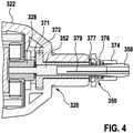
- Teilschnitt einer alternativen Ausführungsform des Aufsatzes aus
Fig. 2a und Fig. 2b - Fig. 5a
- Längsschnitt einer alternativen Ausführungsform des Aufsatzes
- Fig. 5b
- Längsschnitt einer Rührwelle korrespondierend zu der alternativen Ausführungsform des Aufsatzes nach
Fig. 5a - Fig. 5c
- Längsschnitt des Aufsatzes nach
Fig. 5a verbunden mit der Rührwelle nachFig. 5b - Fig. 6a
- Längsschnitt einer weiteren alternativen Ausführungsform des Aufsatzes
- Fig. 6b
- perspektivische Ansicht einer Rührwelle korrespondierend zu der weiteren alternativen Ausführungsform des Aufsatzes nach
Fig. 6a - Fig. 6c
- Längsschnitt der Rührwelle nach
Fig. 6b - Fig. 6d
- Längsschnitt des Aufsatzes nach
Fig. 6a verbunden mit der Rührwelle nachFig. 6b
- Fig. 1a
- Perspective view of a section of a hand tool machine
- Fig. 1b
- Perspective view of an embodiment of the attachment according to the invention
- 1c
- Longitudinal section of the essay
- Figure 2a
- Longitudinal section of another embodiment of the attachment with an accessory interface unit
- Figure 2b
- Longitudinal section of another embodiment of the attachment with an accessory interface unit and stirring unit
- Figure 3a
- Longitudinal section of another embodiment of the attachment with an alternative form of accessory interface unit
- Figure 3b
- Enlarged view of the receiving sleeve
- 3c
- Section of an embodiment of the stirrer shaft corresponding to the embodiment of the accessory interface unit
- 4
- Partial section of an alternative embodiment of the attachment
Figures 2a and 2b - Figure 5a
- Longitudinal section of an alternative embodiment of the attachment
- Figure 5b
- Longitudinal section of an agitator shaft corresponding to the alternative embodiment of the attachment
Figure 5a - Figure 5c
- Longitudinal section of the essay
Figure 5a connected to the agitator shaftFigure 5b - Figure 6a
- Longitudinal section of another alternative embodiment of the attachment
- Figure 6b
- perspective view of an agitator shaft corresponding to the further alternative embodiment of the attachment
Figure 6a - Figure 6c
- Longitudinal section of the agitator shaft
Figure 6b - Figure 6d
- Longitudinal section of the essay
Figure 6a connected to the agitator shaftFigure 6b
In
In
In
Eine Ausführungsform der Zubehörschnittstelleneinheit 350, die für eine kraftschlüssige Verbindung der Rührwelle 332 mit der Koppeleinheit 320 vorgesehen ist, ist in
An dem aus dem Gehäuse 322 des Aufsatzes 300 herausragenden Teil der Aufnahmehülse 352 ist ein Außenkonus 358 vorgesehen. Ferner weist die Zubehörschnittstelleneinheit 350 eine zu dem Außenkonus 358 korrespondierende Spannhülse 354 auf. Mit der Spannhülse 354 ist eine Feder 356 verbunden, die an einem Abstützelement 357 axial abgestützt ist und eine axiale Federkraft auf die Spannhülse 354 ausübt. Das Abstützelement 357 ist beispielhaft ausgeführt als eine Schulter. Die hieraus resultierende Bewegung des Innenkonus der Spannhülse 354 gegen den Außenkonus 358 der Aufnahmehülse 352 übt wiederum eine radiale Kraft auf die Aufnahmehülse 352 aus. Die Spannhülse 354 sowie die Schulter 357 sind beide an dem Außenkonus 358 der Aufnahmehülse 352 angebracht. Somit unterliegen die unter Federkraft stehenden Elemente 354,357 keiner relativen Drehbewegung zueinander, wodurch eine axiale Lagerung entbehrlich ist. Zu Beginn des Einführ- bzw. Löseprozess der Rührwelle 332 mit der Zubehörschnittstelleneinheit 350 wird die Spannhülse 354 gegen die Feder 356 bewegt wodurch die radiale Kraft auf die Aufnahmehülse 352 aufgehoben wird. Nach dem Einführen wird durch Federkraft die Spannhülse 354 gegen die Aufnahmehülse 352 bewegt. Die dadurch wirkende radiale Kraft auf die Aufnahmehülse 352 überträgt sich auf die Rührwelle 332 und resultiert in einer axial als auch radial kraftschlüssigen Verbindung.An
Eine weitere Ausführungsform der Zubehörschnittstelleneinheit 450, die für eine kraft- und formschlüssige Verbindung der Rührwelle 432 mit der Koppeleinheit 420 vorgesehen ist, ist in
Die Aufnahmehülse 452 ist über eine Verbindungswelle 451 mit dem Ausgangselement 428 des Getriebes 424, dargestellt als Sonnenrad zweiter Stufe eines Planetengetriebes, drehfest verbunden, insbesondere durch einpressen. Die Verbindungswelle ist in einem Lager 442 drehbeweglich gelagert. Die radiale Führung der Rührwelle 432 erfolgt in der Aufnahmeöffnung 460 der Aufnahmehülse 452. Zur radialen Mitnahme und axialen Sicherung verfügt die Rührwelle 432 über zumindest ein Verriegelungselement 436, beispielhaft ausgeführt als Flügel. In der Ausführung nach
Die axiale Sicherung der Rührwelle 432 erfolgt über zumindest ein radial bewegliches Verriegelungselement 464, hier kugelförmig ausgeführt, das eine Rastverbindung zusammen mit der Außenkontur des Verriegelungselements 436 der Rührwelle 432 in Form eines Flügels bewirkt. Das Verriegelungselement 464 ist in einer Ausnehmung 468 in Form einer Querbohrung der Aufnahmehülse 452 im Bereich des Verdrehsicherungselements 462 aufgenommen und radial durch einen Federring 466 beaufschlagt. Beim Einführen der Rührwelle 432 drücken die Flügel 436 die korrespondierenden Verriegelungselemente 464 der Zubehörschnittstelleneinheit 450 gegen die radiale Federkraft des Federrings 466 nach außen, bis das Verriegelungselement 464 beim weiteren Einführen axial vor dem Flügel 436 wieder eintaucht und somit die Rührwelle 432 axial sichert. Zum Entnehmen der Rührwelle 432 wird diese aus der Aufnahmehülse 452 herausgezogen, wobei dann der Rastvorgang zwischen dem Verriegelungselementen 464 und dem Flügel 436 axial gegengleich stattfindet.The
In einer alternativen Ausführungsform der Zubehöhrschnittstelle 350 für die kraftschlüssige Verbindung der Rührwelle 332 mit der Koppeleinheit 320 ist ein Abstützelement 377 als Scheibe vorgesehen. Diese Scheibe 377 beaufschlagt aufsatzseitig ein Lager 372, in dem die Aufnahmehülse 352 drehfest gelagert ist. Das Lager 372 ist hierzu derart ausgebildet, dass es aus dem Gehäuse 322 des Aufsatzes 300 herausragt. Auf der anderen Seite der Scheibe 377 stützt sich eine Feder 376 ab, die eine Kraft auf eine Spannhülse 374 ausübt.In an alternative embodiment of the
Die axiale und radiale kraftschlüssige Verbindung zwischen Aufnahmehülse 352 und Rührwelle 332 entsteht analog zu der Ausführungsform in
Während des Betriebs der Rührwelle 332 rotiert die Feder 376 mit der Spannhülse 374. Das Drehverhalten der Scheibe 377 wird bestimmt durch die Reibungsverhältnisse zwischen Scheibe 377 und Lager 372 sowie Scheibe 377 und Feder 376. Ist das Reibungsverhältnis zwischen Scheibe 377 und Feder 376 größer, so rotiert die Feder 376. Andernfalls bleibt die Feder 376 stehen. Die Scheibe 377 wirkt somit als Gleitlager zwischen dem Lager 372 und den sich relativ bewegenden Teilen, welche unter Federkraft stehen.During operation of the
In dieser Ausführungsform wirkt die Feder 376 über die Spannhülse 374 auf die Aufnahmehülse 352. Die Aufnahmehülse stützt sich wiederum über das Ausgangselement 328 und einem weiteren Lager 371 auf dem Lager 372 axial ab. Das Lager 371 ist vorzugsweise in Form einer Scheibe als Gleitlager ausgeführt. Somit ist die Aufnahmehülse 352 mit der Koppeleinheit 320 axial im Wesentlichen spielfrei und durch Federkraft verspannt.In this embodiment, the
In
In
Die Rührwelle 532 weist zumindest ein Verriegelungselement 536 auf, das zu einer zumindest formschlüssigen Verbindung mit dem Verriegelungselement 564 der Zubehörschnittstelleneinheit 550 ausgebildet ist. Das Verriegelungselement 536 der Rührwelle 532 ist beispielhaft als Einbauchung ausgebildet, deren Kontur korrespondierend zur Außenkontur des kugelförmigen Verriegelungselements 564 der Zubehörschnittstelleneinheit 550 ausgebildet ist. Vorteilhaft wird über das Verriegelungselement 564 der Zubehörschnittstelleneinheit 550 und das Verriegelungselement 536 der Rührwelle 532 sowohl eine axiale Sicherung der Rührwelle 532 als auch eine Drehmitnahme der Rührwelle 532 realisiert. In
In
Hierzug ist die Rührwelle 632 an dem Ende, das in das Gehäuse 622 des Aufsatzes 600 eintaucht, spannzangenförmig mit zumindest einem Längsschlitz 679 ausgebildet (siehe
Durch den Längsschlitz 679 ist der Radius der Aufnahmeöffnung 660 der Rührwelle 632 in Abhängigkeit der Einwirkung einer Kraft in radialer Richtung veränderbar. Beim Einschieben der Rührwelle 632 in das Gehäuse 622 des Aufsatzes 600 wird die Rührwelle 632 zunächst entlang des Gleitlagerelements 642 geführt. Schiebt sich die Aufnahmeöffnung 660 der Rührwelle 632 axial über den zylindrischen Fortsatz 629 des Ausgangselements 628, so wird der Konus 661 der Aufnahmeöffnung 660 in dem Bereich von dem zylindrischen Fortsatz 629 kraftbeaufschlagt, in dem der Radius des zylindrischen Fortsatzes 629 gleich oder größer ist als der Radius der Aufnahmeöffnung 660. Durch die Beaufschlagung wird die Rührwelle 632 im Bereich der Aufnahmeöffnung 660 geweitet und es entsteht ein Kraftschluss zwischen der Rührwelle 632 und dem Ausgangselement 628 zur Axial- und Drehsicherung der Koppeleinheit 620 mit der Rühreinheit 630. Die kinematische Umkehr, bei der das Ausgangselement 628 als Aufnahmehülse und somit spannzangenförmig ausgebildet ist und die Rührwelle 632 aufnimmt, ist ebenfalls denkbar.The radius of the receiving
Claims (12)
- Attachment (200; 300; 400; 500; 600) for an electric hand-held power tool (100) for carrying out functions in kitchens, having
a stirring unit (230; 330; 430; 530; 630) which comprises a stirring element (234; 334; 434; 534; 634) and a stirring shaft (232; 332; 432; 532; 632); a coupling unit (220; 320; 420; 520; 620) for transmitting torque from a hand-held power tool (100) to the stirring unit (230; 330; 430; 530; 630), wherein the coupling unit (220; 320; 420; 520; 620) has at least one drive shaft (226; 326; 426; 526; 626) which is able to be coupled to an output shaft (120) of the hand-held power tool (100) for conjoint rotation;
characterized in thata locking unit (210; 310; 510; 610) for locking an attachment (200; 300; 400; 500; 600) to a housing (110) of a hand-held power tool (100) is provided; wherein an accessory interface unit (350; 450; 550; 650) is provided, which establishes a releasable, force- and/or form-fitting connection of the coupling unit (220; 320; 420; 520; 620) to the stirring unit (230; 330; 430; 530; 630) in an axial direction and direction of rotation;wherein the accessory interface unit (350; 450; 550) has a receiving sleeve (352; 452; 552) with a receiving opening (360; 460; 560) for receiving the stirring shaft (332; 432; 532), in which the radial guidance of the stirring shaft (332; 432; 532) takes place. - Attachment (200; 300; 400; 500; 600) according to Claim 1, characterized in that the coupling unit (220; 320; 420; 520; 620) has a transmission (224; 324; 424; 524; 624) with at least one transmission stage for increasing the rotational speed of the stirring shaft (232; 332; 432; 532; 632) with respect to the rotational speed of the drive shaft (226; 326; 526; 626).
- Attachment (200; 300; 400; 500; 600) according to Claim 2, characterized in that the transmission (224; 324; 424; 524; 624) is in the form of a planetary transmission which comprises at least one stage.
- Attachment (500; 600) according to one of the preceding claims, characterized in that the accessory interface unit (550; 650) is formed at least partially in one piece with the transmission (524; 625) of the attachment (500; 600).
- Attachment (300; 400; 500) according to Claim 1, characterized in that the receiving sleeve (352; 452; 552) is connected to an output element (328; 428; 528) of the transmission (324; 424; 524), in particular a sun gear of the transmission (324; 424; 524), for conjoint rotation.
- Attachment (300) according to one of Claims 1 to 5, characterized in that the receiving sleeve (352) is in the form of a collet chuck.
- Attachment (400; 500) according to one of Claims 1 to 6, characterized in that the receiving sleeve (452; 552) has at least one radially movable locking element (464; 564) for axially and/or rotationally locking the stirring shaft (432; 532) in the receiving opening (460; 560).
- Attachment (400) according to one of Claims 1 to 7, characterized in that the receiving sleeve (452) has at least one rotation-prevention element (462) for preventing the stirring shaft (432) from rotating.
- Attachment (400) according to one of Claims 1 to 8, characterized in that the receiving sleeve (452) is connected to an output element (428) of the transmission (424) for conjoint rotation via a connecting shaft (451).
- Attachment (500) according to one of Claims 1 to 9, characterized in that the receiving sleeve (552) is formed in one piece with the output element (528) of the transmission (524).
- Attachment (400) according to one of Claims 7 to 10, characterized in that the stirring shaft (432) has at least one locking element (436) for axial securing and/or rotation prevention, which corresponds to the at least one locking element (464) and/or the at least one rotation-prevention element (462) of the accessory interface unit (450).
- Electrical appliance which has an attachment (200; 300; 400; 500; 600) according to one of Claims 1-11.
Applications Claiming Priority (2)
| Application Number | Priority Date | Filing Date | Title |
|---|---|---|---|
| DE102015217432 | 2015-09-11 | ||
| DE102016214945.8A DE102016214945A1 (en) | 2015-09-11 | 2016-08-11 | Attachment for a hand tool |
Publications (2)
| Publication Number | Publication Date |
|---|---|
| EP3144108A1 EP3144108A1 (en) | 2017-03-22 |
| EP3144108B1 true EP3144108B1 (en) | 2022-03-02 |
Family
ID=56893747
Family Applications (1)
| Application Number | Title | Priority Date | Filing Date |
|---|---|---|---|
| EP16186838.5A Active EP3144108B1 (en) | 2015-09-11 | 2016-09-01 | Attachment for a hand tool |
Country Status (1)
| Country | Link |
|---|---|
| EP (1) | EP3144108B1 (en) |
Family Cites Families (7)
| Publication number | Priority date | Publication date | Assignee | Title |
|---|---|---|---|---|
| US6702038B1 (en) * | 1998-05-22 | 2004-03-09 | Miroslav Sedlacek | Hydraulic motor |
| US5993454A (en) * | 1998-09-29 | 1999-11-30 | Stryker Corporation | Drill attachment for a surgical drill |
| DE102006016804A1 (en) * | 2006-04-10 | 2007-10-11 | Robert Bosch Gmbh | Tool holder for a hammer drill |
| DE202011001477U1 (en) * | 2011-01-13 | 2011-03-24 | Metabowerke Gmbh | Attachment for a hand-held machine tool |
| DE102011084122A1 (en) | 2011-10-07 | 2013-04-11 | Robert Bosch Gmbh | Accessory device for hand-held power tool e.g. froth producing apparatus used in household application, has function unit that is provided with stirring element for production of milk froth |
| DE102012203425A1 (en) * | 2012-03-05 | 2013-09-05 | Robert Bosch Gmbh | Accessory device for use with hand-held machine tool in system for use as camping and barbecue set, comprises household functional unit, drive shaft and coupling element for connecting drive shaft with output shaft of hand-held machine tool |
| EP2857127B1 (en) * | 2013-10-02 | 2016-03-16 | Eugen Fahrion GmbH & Co. KG | Tool holder with a collet chuck for clamping a tool |
-
2016
- 2016-09-01 EP EP16186838.5A patent/EP3144108B1/en active Active
Also Published As
| Publication number | Publication date |
|---|---|
| EP3144108A1 (en) | 2017-03-22 |
Similar Documents
| Publication | Publication Date | Title |
|---|---|---|
| EP2262601B1 (en) | Hand-held machine tool | |
| EP1930125B1 (en) | Attachment for a hand tool | |
| EP2627483B1 (en) | Hand-held electric tool having a spindle-locking device | |
| DE102012206162B4 (en) | Food processor with a three-stage planetary gear | |
| EP2745990A2 (en) | Tool attachment for a manual tool machine | |
| WO2008064955A1 (en) | Hand-held power tool | |
| WO2008068103A1 (en) | Handheld tool | |
| EP2140931B1 (en) | Agitating machine with length-adjustable tool holder | |
| DE2855359B2 (en) | Dental handpiece | |
| EP2132453B1 (en) | Gearbox device | |
| DE102012212417B4 (en) | switching unit | |
| EP2962812A2 (en) | Tool attachment and tool system | |
| EP0868264B1 (en) | Electric hand tool | |
| DE102012212404B4 (en) | Hand machine tool device | |
| EP3144108B1 (en) | Attachment for a hand tool | |
| DE102016214945A1 (en) | Attachment for a hand tool | |
| EP2011608B1 (en) | Hand tool with friction clutch | |
| WO2017182036A1 (en) | Actuation device for a motor vehicle transmission and shifting unit | |
| DE102012007958A1 (en) | Electric power tool e.g. drilling machine, for workpiece, has ancillary gear comprising housing with front ends, which are selectively linked with flange section, and one countershaft or other countershaft connected with drive shaft | |
| DE102008064424B4 (en) | Plug-in coupling device | |
| DE102015209017A1 (en) | Intermediate attachment for a hand tool | |
| DE102015112059B4 (en) | Long-neck sander | |
| EP3503780B1 (en) | Mounting and drive device for tools in a food processor | |
| EP3287056A1 (en) | Multifunctional coupling device for a kitchen appliance | |
| EP2104594B1 (en) | Hand held power tool |
Legal Events
| Date | Code | Title | Description |
|---|---|---|---|
| PUAI | Public reference made under article 153(3) epc to a published international application that has entered the european phase |
Free format text: ORIGINAL CODE: 0009012 |
|
| STAA | Information on the status of an ep patent application or granted ep patent |
Free format text: STATUS: THE APPLICATION HAS BEEN PUBLISHED |
|
| AK | Designated contracting states |
Kind code of ref document: A1 Designated state(s): AL AT BE BG CH CY CZ DE DK EE ES FI FR GB GR HR HU IE IS IT LI LT LU LV MC MK MT NL NO PL PT RO RS SE SI SK SM TR |
|
| AX | Request for extension of the european patent |
Extension state: BA ME |
|
| STAA | Information on the status of an ep patent application or granted ep patent |
Free format text: STATUS: REQUEST FOR EXAMINATION WAS MADE |
|
| 17P | Request for examination filed |
Effective date: 20170922 |
|
| RBV | Designated contracting states (corrected) |
Designated state(s): AL AT BE BG CH CY CZ DE DK EE ES FI FR GB GR HR HU IE IS IT LI LT LU LV MC MK MT NL NO PL PT RO RS SE SI SK SM TR |
|
| STAA | Information on the status of an ep patent application or granted ep patent |
Free format text: STATUS: EXAMINATION IS IN PROGRESS |
|
| 17Q | First examination report despatched |
Effective date: 20191007 |
|
| RAP1 | Party data changed (applicant data changed or rights of an application transferred) |
Owner name: ROBERT BOSCH GMBH |
|
| STAA | Information on the status of an ep patent application or granted ep patent |
Free format text: STATUS: EXAMINATION IS IN PROGRESS |
|
| GRAP | Despatch of communication of intention to grant a patent |
Free format text: ORIGINAL CODE: EPIDOSNIGR1 |
|
| STAA | Information on the status of an ep patent application or granted ep patent |
Free format text: STATUS: GRANT OF PATENT IS INTENDED |
|
| INTG | Intention to grant announced |
Effective date: 20211005 |
|
| GRAS | Grant fee paid |
Free format text: ORIGINAL CODE: EPIDOSNIGR3 |
|
| GRAA | (expected) grant |
Free format text: ORIGINAL CODE: 0009210 |
|
| STAA | Information on the status of an ep patent application or granted ep patent |
Free format text: STATUS: THE PATENT HAS BEEN GRANTED |
|
| AK | Designated contracting states |
Kind code of ref document: B1 Designated state(s): AL AT BE BG CH CY CZ DE DK EE ES FI FR GB GR HR HU IE IS IT LI LT LU LV MC MK MT NL NO PL PT RO RS SE SI SK SM TR |
|
| REG | Reference to a national code |
Ref country code: GB Ref legal event code: FG4D Free format text: NOT ENGLISH |
|
| REG | Reference to a national code |
Ref country code: CH Ref legal event code: EP Ref country code: AT Ref legal event code: REF Ref document number: 1471876 Country of ref document: AT Kind code of ref document: T Effective date: 20220315 |
|
| REG | Reference to a national code |
Ref country code: DE Ref legal event code: R096 Ref document number: 502016014574 Country of ref document: DE |
|
| REG | Reference to a national code |
Ref country code: IE Ref legal event code: FG4D Free format text: LANGUAGE OF EP DOCUMENT: GERMAN |
|
| REG | Reference to a national code |
Ref country code: LT Ref legal event code: MG9D |
|
| REG | Reference to a national code |
Ref country code: NL Ref legal event code: MP Effective date: 20220302 |
|
| PG25 | Lapsed in a contracting state [announced via postgrant information from national office to epo] |
Ref country code: SE Free format text: LAPSE BECAUSE OF FAILURE TO SUBMIT A TRANSLATION OF THE DESCRIPTION OR TO PAY THE FEE WITHIN THE PRESCRIBED TIME-LIMIT Effective date: 20220302 Ref country code: RS Free format text: LAPSE BECAUSE OF FAILURE TO SUBMIT A TRANSLATION OF THE DESCRIPTION OR TO PAY THE FEE WITHIN THE PRESCRIBED TIME-LIMIT Effective date: 20220302 Ref country code: NO Free format text: LAPSE BECAUSE OF FAILURE TO SUBMIT A TRANSLATION OF THE DESCRIPTION OR TO PAY THE FEE WITHIN THE PRESCRIBED TIME-LIMIT Effective date: 20220602 Ref country code: LT Free format text: LAPSE BECAUSE OF FAILURE TO SUBMIT A TRANSLATION OF THE DESCRIPTION OR TO PAY THE FEE WITHIN THE PRESCRIBED TIME-LIMIT Effective date: 20220302 Ref country code: HR Free format text: LAPSE BECAUSE OF FAILURE TO SUBMIT A TRANSLATION OF THE DESCRIPTION OR TO PAY THE FEE WITHIN THE PRESCRIBED TIME-LIMIT Effective date: 20220302 Ref country code: ES Free format text: LAPSE BECAUSE OF FAILURE TO SUBMIT A TRANSLATION OF THE DESCRIPTION OR TO PAY THE FEE WITHIN THE PRESCRIBED TIME-LIMIT Effective date: 20220302 Ref country code: BG Free format text: LAPSE BECAUSE OF FAILURE TO SUBMIT A TRANSLATION OF THE DESCRIPTION OR TO PAY THE FEE WITHIN THE PRESCRIBED TIME-LIMIT Effective date: 20220602 |
|
| PG25 | Lapsed in a contracting state [announced via postgrant information from national office to epo] |
Ref country code: PL Free format text: LAPSE BECAUSE OF FAILURE TO SUBMIT A TRANSLATION OF THE DESCRIPTION OR TO PAY THE FEE WITHIN THE PRESCRIBED TIME-LIMIT Effective date: 20220302 Ref country code: LV Free format text: LAPSE BECAUSE OF FAILURE TO SUBMIT A TRANSLATION OF THE DESCRIPTION OR TO PAY THE FEE WITHIN THE PRESCRIBED TIME-LIMIT Effective date: 20220302 Ref country code: GR Free format text: LAPSE BECAUSE OF FAILURE TO SUBMIT A TRANSLATION OF THE DESCRIPTION OR TO PAY THE FEE WITHIN THE PRESCRIBED TIME-LIMIT Effective date: 20220603 Ref country code: FI Free format text: LAPSE BECAUSE OF FAILURE TO SUBMIT A TRANSLATION OF THE DESCRIPTION OR TO PAY THE FEE WITHIN THE PRESCRIBED TIME-LIMIT Effective date: 20220302 |
|
| PG25 | Lapsed in a contracting state [announced via postgrant information from national office to epo] |
Ref country code: NL Free format text: LAPSE BECAUSE OF FAILURE TO SUBMIT A TRANSLATION OF THE DESCRIPTION OR TO PAY THE FEE WITHIN THE PRESCRIBED TIME-LIMIT Effective date: 20220302 |
|
| PG25 | Lapsed in a contracting state [announced via postgrant information from national office to epo] |
Ref country code: SM Free format text: LAPSE BECAUSE OF FAILURE TO SUBMIT A TRANSLATION OF THE DESCRIPTION OR TO PAY THE FEE WITHIN THE PRESCRIBED TIME-LIMIT Effective date: 20220302 Ref country code: SK Free format text: LAPSE BECAUSE OF FAILURE TO SUBMIT A TRANSLATION OF THE DESCRIPTION OR TO PAY THE FEE WITHIN THE PRESCRIBED TIME-LIMIT Effective date: 20220302 Ref country code: RO Free format text: LAPSE BECAUSE OF FAILURE TO SUBMIT A TRANSLATION OF THE DESCRIPTION OR TO PAY THE FEE WITHIN THE PRESCRIBED TIME-LIMIT Effective date: 20220302 Ref country code: PT Free format text: LAPSE BECAUSE OF FAILURE TO SUBMIT A TRANSLATION OF THE DESCRIPTION OR TO PAY THE FEE WITHIN THE PRESCRIBED TIME-LIMIT Effective date: 20220704 Ref country code: EE Free format text: LAPSE BECAUSE OF FAILURE TO SUBMIT A TRANSLATION OF THE DESCRIPTION OR TO PAY THE FEE WITHIN THE PRESCRIBED TIME-LIMIT Effective date: 20220302 Ref country code: CZ Free format text: LAPSE BECAUSE OF FAILURE TO SUBMIT A TRANSLATION OF THE DESCRIPTION OR TO PAY THE FEE WITHIN THE PRESCRIBED TIME-LIMIT Effective date: 20220302 |
|
| PG25 | Lapsed in a contracting state [announced via postgrant information from national office to epo] |
Ref country code: IS Free format text: LAPSE BECAUSE OF FAILURE TO SUBMIT A TRANSLATION OF THE DESCRIPTION OR TO PAY THE FEE WITHIN THE PRESCRIBED TIME-LIMIT Effective date: 20220702 Ref country code: AL Free format text: LAPSE BECAUSE OF FAILURE TO SUBMIT A TRANSLATION OF THE DESCRIPTION OR TO PAY THE FEE WITHIN THE PRESCRIBED TIME-LIMIT Effective date: 20220302 |
|
| REG | Reference to a national code |
Ref country code: DE Ref legal event code: R097 Ref document number: 502016014574 Country of ref document: DE |
|
| PLBE | No opposition filed within time limit |
Free format text: ORIGINAL CODE: 0009261 |
|
| STAA | Information on the status of an ep patent application or granted ep patent |
Free format text: STATUS: NO OPPOSITION FILED WITHIN TIME LIMIT |
|
| PG25 | Lapsed in a contracting state [announced via postgrant information from national office to epo] |
Ref country code: DK Free format text: LAPSE BECAUSE OF FAILURE TO SUBMIT A TRANSLATION OF THE DESCRIPTION OR TO PAY THE FEE WITHIN THE PRESCRIBED TIME-LIMIT Effective date: 20220302 |
|
| 26N | No opposition filed |
Effective date: 20221205 |
|
| PG25 | Lapsed in a contracting state [announced via postgrant information from national office to epo] |
Ref country code: SI Free format text: LAPSE BECAUSE OF FAILURE TO SUBMIT A TRANSLATION OF THE DESCRIPTION OR TO PAY THE FEE WITHIN THE PRESCRIBED TIME-LIMIT Effective date: 20220302 |
|
| PG25 | Lapsed in a contracting state [announced via postgrant information from national office to epo] |
Ref country code: MC Free format text: LAPSE BECAUSE OF FAILURE TO SUBMIT A TRANSLATION OF THE DESCRIPTION OR TO PAY THE FEE WITHIN THE PRESCRIBED TIME-LIMIT Effective date: 20220302 |
|
| REG | Reference to a national code |
Ref country code: CH Ref legal event code: PL |
|
| GBPC | Gb: european patent ceased through non-payment of renewal fee |
Effective date: 20220901 |
|
| REG | Reference to a national code |
Ref country code: BE Ref legal event code: MM Effective date: 20220930 |
|
| PG25 | Lapsed in a contracting state [announced via postgrant information from national office to epo] |
Ref country code: LU Free format text: LAPSE BECAUSE OF NON-PAYMENT OF DUE FEES Effective date: 20220901 |
|
| PG25 | Lapsed in a contracting state [announced via postgrant information from national office to epo] |
Ref country code: LI Free format text: LAPSE BECAUSE OF NON-PAYMENT OF DUE FEES Effective date: 20220930 Ref country code: IT Free format text: LAPSE BECAUSE OF FAILURE TO SUBMIT A TRANSLATION OF THE DESCRIPTION OR TO PAY THE FEE WITHIN THE PRESCRIBED TIME-LIMIT Effective date: 20220302 Ref country code: IE Free format text: LAPSE BECAUSE OF NON-PAYMENT OF DUE FEES Effective date: 20220901 Ref country code: CH Free format text: LAPSE BECAUSE OF NON-PAYMENT OF DUE FEES Effective date: 20220930 |
|
| PG25 | Lapsed in a contracting state [announced via postgrant information from national office to epo] |
Ref country code: BE Free format text: LAPSE BECAUSE OF NON-PAYMENT OF DUE FEES Effective date: 20220930 |
|
| PG25 | Lapsed in a contracting state [announced via postgrant information from national office to epo] |
Ref country code: GB Free format text: LAPSE BECAUSE OF NON-PAYMENT OF DUE FEES Effective date: 20220901 |
|
| REG | Reference to a national code |
Ref country code: AT Ref legal event code: MM01 Ref document number: 1471876 Country of ref document: AT Kind code of ref document: T Effective date: 20220901 |
|
| PGFP | Annual fee paid to national office [announced via postgrant information from national office to epo] |
Ref country code: FR Payment date: 20230919 Year of fee payment: 8 |
|
| PG25 | Lapsed in a contracting state [announced via postgrant information from national office to epo] |
Ref country code: AT Free format text: LAPSE BECAUSE OF NON-PAYMENT OF DUE FEES Effective date: 20220901 |
|
| PGFP | Annual fee paid to national office [announced via postgrant information from national office to epo] |
Ref country code: DE Payment date: 20231124 Year of fee payment: 8 |
|
| PG25 | Lapsed in a contracting state [announced via postgrant information from national office to epo] |
Ref country code: HU Free format text: LAPSE BECAUSE OF FAILURE TO SUBMIT A TRANSLATION OF THE DESCRIPTION OR TO PAY THE FEE WITHIN THE PRESCRIBED TIME-LIMIT; INVALID AB INITIO Effective date: 20160901 |